Review

Recent Advancements in Polypropylene Fibre-Reinforced 3D-Printed Concrete: Insights into Mix Ratios, Testing Procedures, and Material Behaviour

1
Centre for Critical Infrastructure, School of Civil Engineering, University College Dublin, D04 V1W8 Belfield, Ireland
2
Construct Innovate, School of Civil Engineering, University College Dublin, D04 V1W8 Belfield, Ireland
*
Authors to whom correspondence should be addressed.
J. Compos. Sci. 2025, 9(6), 292; https://doi.org/10.3390/jcs9060292
Submission received: 22 April 2025 / Revised: 15 May 2025 / Accepted: 22 May 2025 / Published: 6 June 2025
(This article belongs to the Special Issue Feature Papers in Journal of Composites Science in 2025)

Abstract

This review presents a comprehensive analysis of polypropylene (PP) fibre incorporation in three-dimensional printed concrete (3DPC), focusing on the material behaviour in both fresh and hardened states. PP fibres play a critical role in improving rheological properties such as buildability, flowability, and extrudability. While increased fibre content enhances interlayer bonding and shape retention through the fibre bridging mechanism, it also raises yield stress and viscosity, which may compromise extrudability. In the hardened state, PP fibres contribute to improvements in compressive and flexural strength up to an optimal dosage, beyond which performance may decline due to fibre clustering and reduced packing density. When aligned with the printing direction, fibres are particularly effective in mitigating shrinkage-induced cracking by redistributing internal tensile stress. However, their inclusion can lead to a slight increase in porosity and promote mechanical anisotropy. This review also discusses mix design parameters, fibre characteristics, and experimental protocols, while identifying key research gaps including the lack of standardized testing methods, limited understanding of fibre orientation effects, and insufficient exploration of hybrid fibre systems. Based on the synthesis of reported studies, optimal print quality and structural consistency have been associated with the use of 6 mm long fibres, nozzle diameters of 4 to 6 mm, and printing speeds ranging from 40 to 60 mm/s. Overall, PP fibre reinforcement shows strong potential for enhancing the structural integrity and dimensional stability of 3D-printed concrete, while emphasizing the need for further studies to optimize its use in practice.

1. Introduction

Three-dimensional printed concrete printing (3DPC) has emerged in recent years as an innovative construction technology, representing a significant advancement over conventional construction methods [1,2,3]. This additive manufacturing technique eliminates the need for formwork, thus significantly reducing construction time, costs, and waste generation [4]. The primary stages of the 3DPC process include material mixing, pumping, and robotic-layered extrusion guided by digital models, enabling precise, efficient, and sustainable construction practices. As illustrated in Figure 1, the 3D concrete printing process specifically involves three key stages: material mixing, pumping, and robotic-layered extrusion guided by a predesigned digital path [4]. A predefined digital path is designed and inputted into the printer, guiding the 3D concrete printer on a gantry girder, depositing concrete via a robotic arm [5]. Despite these advantages, 3D-printed concrete faces inherent challenges, notably reduced mechanical strength and susceptibility to shrinkage-induced cracking when compared to traditional cast concrete [4]. Consequently, enhancing the mechanical properties and reducing the brittleness of printed concrete is critical to expanding its practical applications.
To address these limitations, numerous reinforcement strategies have been explored, including the integration of supplementary cementitious materials (SCMs) and various fibre reinforcements. The incorporation of SCMs such as fly ash (FA), silica fume (SF), ground-granulated blast furnace slag (GGBS), and nanosilica (NS) is well-documented for enhancing both fresh and hardened state properties of concrete, optimizing rheological behaviour, reducing environmental impact, and improving overall material durability [6,7,8,9,10]. Fibre reinforcement, another prominent enhancement strategy, significantly improves tensile strength, ductility, toughness, and resistance to shrinkage cracking. Fibres can be categorized into rigid fibres (e.g., steel fibres), flexible fibres (e.g., polypropylene (PP) and polyvinyl alcohol (PVA) fibres), and fibre textiles or grids (e.g., glass fibre textile (GFT)). Rigid fibres enhance mechanical strength and fracture toughness through alignment effects during extrusion [11,12]. Flexible fibres improve buildability and reduce shrinkage-induced cracking through their fibre-bridging capability, though they may increase porosity [13,14,15]. Fibre textiles or grids strategically enhance flexural strength and toughness without compromising workability [16]. Additionally, advanced reinforcement strategies such as fibre-reinforced polymer (FRP) wrapping and polymeric or metallic fibres have been explored, demonstrating improved compressive strength and ductility [17,18].
Among these fibres, polypropylene (PP) fibres offer distinct advantages, making them particularly suitable for reinforcing 3D-printed concrete. PP fibres are characterized by low density, excellent chemical resistance, affordability, and ease of dispersion within concrete mixtures [19,20,21]. Studies indicate that PP fibres effectively improve buildability and mitigate shrinkage-induced cracking due to their fibre-bridging effect. This significantly enhances the interlayer bonding, reduces anisotropy in mechanical properties, and improves the overall toughness of 3D-printed concrete structures [22,23]. Although PP fibres can slightly reduce compressive strength due to fibre clustering and increased porosity, their benefits in controlling cracking and enhancing structural durability far outweigh these drawbacks, particularly when optimized through careful mix design.
Despite growing research on fibre-reinforced 3D-printed concrete, comprehensive reviews specifically focused on the performance implications of PP fibres remain relatively scarce. This review systematically examines the existing literature on PP fibre-reinforced 3D-printed concrete, emphasizing mix design strategies, raw materials characterization, experimental methodologies, and their influence on fresh state rheological behaviour, printability, and hardened state performance, including compressive and flexural strengths, shrinkage, fracture toughness, and porosity. Furthermore, critical research gaps such as the lack of standardized testing protocols, insufficient studies addressing fibre orientation and length effects, and limited exploration of hybrid fibre systems are identified and discussed. By synthesizing current knowledge and highlighting these areas, this review aims to provide valuable insights and guidance for the development and optimization of PP fibre-reinforced 3D-printed concrete in future research and practical applications.

2. Raw Materials and Mix

The mix design for 3D-printed concrete must have the properties to provide the necessary mechanical strength, pumpability, extrudability, and buildability [4]. These properties are crucial to ensure it can be extruded in a smooth manner and can then hold its shape once extruded. To improve one of these parameters, it has an inverse effect on the other, so it is vital to find the line where both parameters are being satisfied. Some materials can help achieve this, such as admixtures and SCMs.

2.1. Secondary Cementitious Materials (SCMs)

It is seen in various studies that 3D-printed concrete requires a high cement content, which is not a sustainable solution as cement is responsible for a large portion of greenhouse gases. High cement content also causes an increase in the heat of hydration, which can increase the drying shrinkage of the concrete [4]. A way to decrease the need for cement is to use SCMs. They reduce the cement concrete in the mix and improve the mechanical and durability properties of the concrete along with the wet state of the concrete mix [4]. Forms of SCMs include FA, SF, and GGBS [24,25]. These are commonly used to enhance the strength, durability, and rheological properties [26].

2.1.1. Fly Ash (FA)

FA is a fine powder that is a by-product of coal combustion in power plants [26]. The effects that FA has on concrete are, it enhances workability, reduces the heat that is generated during hydration process, and increases long-term strength and durability of the concrete [27]. However it also decreases the static yield stress and viscosity [27], which causes the bottom layer in printing to deform. It is seen that the finer the material is, the better the flowability due to the enhanced dispersion and reduced particle–particle interactions [28]. The optimal FA replacement is 20%, which strikes a balance between fluidity, strength, and buildability. The buildability issue FA causes can be counteracted by incorporating nano clays, improving flocculation strength and shear-yield stress [26].

2.1.2. Silica Fume (SF)

Silica fume is a formed as a result of silicon and ferrosilicon alloy production [29]. Using it in concrete causes a reaction with calcium hydroxide (CH), which is produced during hydration to form an additional calcium silicate hydrate (C-S-H) gel [26]. Silica fume hosts many improvements to the concrete, including increased mechanical strength, improved durability, protection against chemical attack, sulfate attack, ASR, chloride iron corrosion, improved workability, and enhanced thermal resistance against thermal cracking [26]. A study reported that 2 wt.% of SF caused the buildability to increase by 117% when put into comparison to the control mix [30].

2.1.3. Ground-Granulated Blast-Furnace Slag (GGBS)

GGBS is a waste material that is produced by the iron and steel industry. It is a reactive pozzolan obtained by rapidly quenching molten slag from a blast furnace with water or steam [26]. This gives off a material that is glassy and granular [29]. Like SF and FA, GGBS also forms additional C-S-H gel due to its reaction with CH. Therefore, this improves the material’s strength and durability, and GGBS is also responsible for reducing the amount of heat generated from the hydration reaction [26]. A study, ref. [31], discovered that the optimal mix design contained the following amounts: 20 wt.% FA, 15 wt.% SF, and 10 wt.% GGBS. This mix provided desirable rheological properties for printing and obtained a compressive strength of 56.3 MPa, which was higher than the cast specimens achieved [26].

2.2. Admixtures

The rheological properties have an effect on the extrudability, buildability, and pumpability. These properties can be altered through admixtures such as superplasticizers and accelerators.

2.2.1. Superplasticizers

Superplasticizers are polymeric substances that are used to decrease the water demands that the concrete requires and increase its flow while not affecting the mechanical strength [32]. They can reduce the water requirement by over 30% [33]. An effective type of superplasticizer is a poly-carboxylic ether-type (PCE); such superplasticizers are efficient, boasting a high water-reducing capacity [34]. It was compared with Naphthalene Sulfonate Formaldehyde (NSF), and the results concluded that both superplasticizers reduced the concrete’s dynamic yield stress and thixotropic behaviour [35]. This is ideal for fibre-induced concrete as the fibres increase the dynamic yield stress and thixotropic behaviour, which provides the concrete mix a good balance [33].

2.2.2. Accelerators

Accelerators are an admixture used to reduce the time it takes for the concrete to set and, therefore, improve the mix’s buildability. Lithium carbonate is a type of accelerator that reacts with cement, causing an increase in static yield stress and positively affecting buildability [36]. However, this reduces the extrudability and open time for printing, weakening the interlayer strength and impacting the printing process [37]. A proposed solution is to spray the mix through the print head instead of mixing it beforehand, which would provide a more considerable open time for printing. Another accelerator is Calcium Formate (CF), which improves workability by reducing dynamic and static yield stress and accelerates hydration [38]. Calcium chloride is said to be the most effective accelerator, but it causes steel corrosion [33]. This is not a problem for polypropylene fibres, so it could be seen as a viable accelerator.

2.3. Fibre Types

Many different types of fibres fall into either the high or low elastic modulus group. PP fibre falls into the low elastic group, along with the likes of polyethylene fibres [39]. These fibres are primarily used for crack mitigation. The high elastic modulus group contains steel fibre, along with others. These fibres increase concrete’s rigidity, tensile and shear strength [39]. Table 1 shows the properties of PP fibres, polyethylene, and steel fibres.

2.3.1. Polypropylene Fibres (PP)

PP fibre is a synthetic linear polymer obtained through propylene polymerization [41]. Many of its characteristics are beneficial for use in 3D-printed concrete, such as its lightweight properties, elevated strength, exceptional toughness, resistance to corrosion, and adequate heat insulation [41]. It is a fibre that falls into the low elastic modulus group of fibres. PP has good ductility and is highly effective in mitigating plastic shrinking and reducing cracking [39]. In a study [42], the addition of 0.5% fibre led to a 27% reduction in shrinkage when put in comparison to the specimen without fibres. This occurs due to the energy that the fibres can absorb and the orientation of the fibres, which has a bridging effect through the cracks in the concrete-caused shrinkage [42].

2.3.2. Polyethylene Fibres (PE)

PE fibre is made from polymerized polyethylene units. It has various forms, such as monofilaments, continuous filament yarns, and staple fibre [41]. In a study by Ding, Xiao [43], PE fibres were incorporated into a recycled sand mix. The recycled sand negatively affected the properties of the concrete, and it was seen that the PE fibres could counteract these effects. The study discovered a 400% increase in flexural strength for 1.4% PE fibre dosage compared to 0.25% [43]. The factors driving these improvements are strong interfacial bonding between PE fibres and the matrix and their high tensile strength. The study also compares PE fibres at lengths of 6 mm and 12 mm; the longer length bridge cracks more effectively and shows improved fracture energy when compared to the shorter fibre. However, it causes issues with extrudability [44]. Compared to PP fibres, Polyethylene fibres have greater tensile strength and better interfacial bonding, resulting in higher flexural strength, but PE fibres are better at controlling shrinkage. Compared to steel fibres, the PE fibres are more ductile but have lesser tensile and flexural strength.

2.3.3. Steel Fibres

Steel fibres are excellent fibres that have many advantages, such as the enhancement of fracture resistance, impact resistance, fatigue resistance, and bending resistance, on top of tenacity and durability [41]. They manufacture cold-drawn wire, cut sheet, melt-extracted, mill cut, and modified cold-drawn wire. A study [45] found that using 6mm short steel fibres significantly increased the flexural strength by up to 500% compared to the unreinforced printed concrete, which was twice as strong as the casted sample. Steel fibres provide superior properties for high-load and durable structures compared to polypropylene. PP fibres are more effective for enhancing ductility, flexibility, and crack resistance and are more suitable for lightweight structures [41]. Steel fibres can be combined with other fibres such as PP, PVA, and carbon fibres. Doing this allows the concrete to gain high strength from the steel. Also, it allows for the concrete to gain other fibre benefits, such as polypropylene crack mitigation properties [41].

2.4. Mixes from Literature Review

A detailed examination of Table 2 reveals a diverse range of fibre types and contents used in 3D-printed concrete (3DPC) mixes to enhance performance characteristics, including interlayer bonding, tensile strength, shrinkage control, and buildability. PP fibres are the most widely used, appearing in over 15 mixes with volumetric dosages ranging from 0.1% to 1.5%. These synthetic fibres are preferred for their crack-bridging capabilities and compatibility with extrusion-based printing. The optimal performance was observed around 0.5–1.0%, where improvements in buildability and interlayer strength were significant, without critically compromising extrudability. However, as the dosage of fibres increase, particularly at 1.5%, mixes tend to require higher superplasticizer (SP) dosages (up to 5.95 kg/m3) and exhibit increased static and dynamic yield stress, which can negatively impact print stability.
Polyethylene (PE) fibres, used in incremental dosages from 0.25% to 1.4%, were found to contribute significantly. Notably, the mix with 1.4% PE fibres demonstrated SP demand (1.98%) and reduced extrudability. The longer PE fibres also posed alignment challenges in narrow nozzles, affecting filament continuity. Steel fibres, incorporated at dosages of 0.5% and 1.0%, primarily enhanced flexural and compressive strengths. Their high modulus and aspect ratio contribute to better post-cracking behaviour, but their high density and rigidity limit their use in mixes requiring high pumpability and print precision.
In addition to single-fibre systems, several hybrid combinations were evaluated, particularly PP and PET (polyethylene terephthalate) blends in volumetric ratios ranging from 0.2PP + 0.8PET to 0.8PP + 0.2PET. These hybrids aim to synergize the ductility and shrinkage resistance of PP with the stiffness and tensile capacity of PET. Although promising, these mixes exhibited elevated plastic viscosities and required fine-tuning of admixture content to avoid print defects such as nozzle clogging or filament instability. Further, mixes using recycled PET and PP fibres indicated potential for sustainable construction, but data on long-term durability, fibre dispersion, and fibre–matrix interfacial bonding are still limited.
Advanced mixes also featured alternative fibre types such as polyvinyl alcohol (PVA) and polyacrylonitrile (PAN). For instance, PVA at 1.82% by mass and PAN up to 0.4% by volume (relative to sand) were used in textile-reinforced or ultra-ductile systems. These fibres demonstrated good synergy with low water-to-binder (W/B) ratios (e.g., 0.26–0.3) and performed well under flexural loading; however, they introduced challenges in achieving uniform dispersion and preventing fibre clumping during mixing.
In summary, the analysis shows that fibre type, content, and interaction with admixtures are critical to optimizing printability and mechanical performance in 3DPC. Polypropylene remains the most balanced choice in terms of processability and performance, whereas PE and steel fibres are more suitable for applications requiring higher load-bearing or energy dissipation. Hybrid systems, especially involving recycled fibres, present a promising research direction but require further validation. Future work should focus on tailoring fibre geometry (length, diameter, aspect ratio) and orientation relative to the print path to develop anisotropic behaviour and improve structural efficiency.

2.5. Printing Parameters Design

The following discussion addresses 3DPC in general. Currently, there is limited research specifically focused on the effect of printing parameters on PP fiber-reinforced 3DPC. Printing parameters play a large role in how the printed structure performs; the way in which the printing parameters and mix composition interact is a key area to be explored. Key parameters such as nozzle diameter, layer height, and printing speed have a significant role in the determination of the print quality, buildability, and mechanical performance.

2.5.1. Nozzle Diameter

The nozzle diameter significantly affects the mechanical properties and geometric accuracy of the printed strands. Larger nozzle diameters facilitate material flow by reducing shear stress at the nozzle exit, thus decreasing extrusion resistance and enhancing buildability. However, excessively large nozzle diameters lead to increased filament width, reducing the precision and surface smoothness of printed components [55,56]. Conversely, smaller nozzle diameters enhance printing accuracy and improve fibre alignment along the printing direction, thereby substantially improving mechanical performance. Nonetheless, smaller diameters increase the risk of clogging and extrusion resistance, requiring careful selection based on the rheological characteristics of the concrete mixture [57].

2.5.2. Layer Height

Layer height is another critical factor influencing the interlayer bonding strength and mechanical performance of printed concrete. Lower layer heights, despite resulting in increased printing times and more interfaces, provide better interface adhesion, denser interlayer regions, and improved overall flexural and fracture properties. Smaller layer heights minimize interface defects such as increased porosity and crack propagation, enhancing the durability and mechanical robustness of the printed structures. Higher layer heights, however, often induce interlayer defects, increasing porosity and weakening interlayer bonding, ultimately diminishing the strength and durability of the final printed element [58,59,60].

2.5.3. Printing Speed

Printing speed directly impacts the accuracy, interlayer adhesion, and overall quality of 3D-printed structures. Higher printing speeds reduce material extrusion per unit length, leading to thinner and narrower filaments, which compromise the buildability and geometrical accuracy of printed layers. Additionally, rapid printing speeds negatively affect interlayer bonding, exacerbating interfacial defects and increasing void formation, thereby diminishing structural integrity and mechanical performance [61,62]. Conversely, moderate to slower printing speeds enhance the stability and quality of the printed layers, mitigating stress concentrations and resulting in improved interlayer bonding strength and overall print quality [57,60].

3. Experimental Procedure for 3D-Printed Concrete

3.1. Mixing Procedure

The mixing procedure involves mixing the dry ingredients first, then mixing with the wet ingredients, and then adding the fibres in for a final mix. In one study [47], the mix consisted of “ordinary Portland cement, according to IS 8112: 2013 and densified silica fume (SF)” as the binder. For the aggregate, “sand with a maximum particle size of 2.36 mm and a specific gravity of 2.65 and fineness moduli of 2.75 was used”. The superplasticiser used was a “polycarboxylate ether-based superplasticizer (SP) in liquid form with 48.48 wt.% solids and having pH of 6.8 and a cellulose-based VMA”. Lastly, fibres were included [47]. A Hobart planetary mixer was used for the preparation of the concrete mix. A mixing speed of 107 rpm was used for 2 min on the dry materials to create a homogeneous dry mixture. After this, the water was added and mixed for 1 min. Once that step was completed, the steel fibres were added, and the mixing was resumed for 1 min at 361 rpm. The mixing was paused for 30 s to scrape the bowl and then resumed for 2 min at 198 rpm to achieve a homogeneous mix [47].

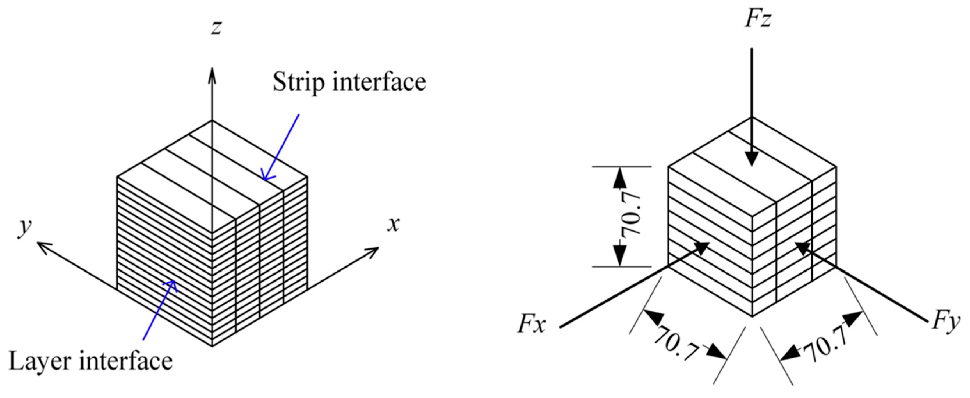
3.2. Flexural and Compressive Tests
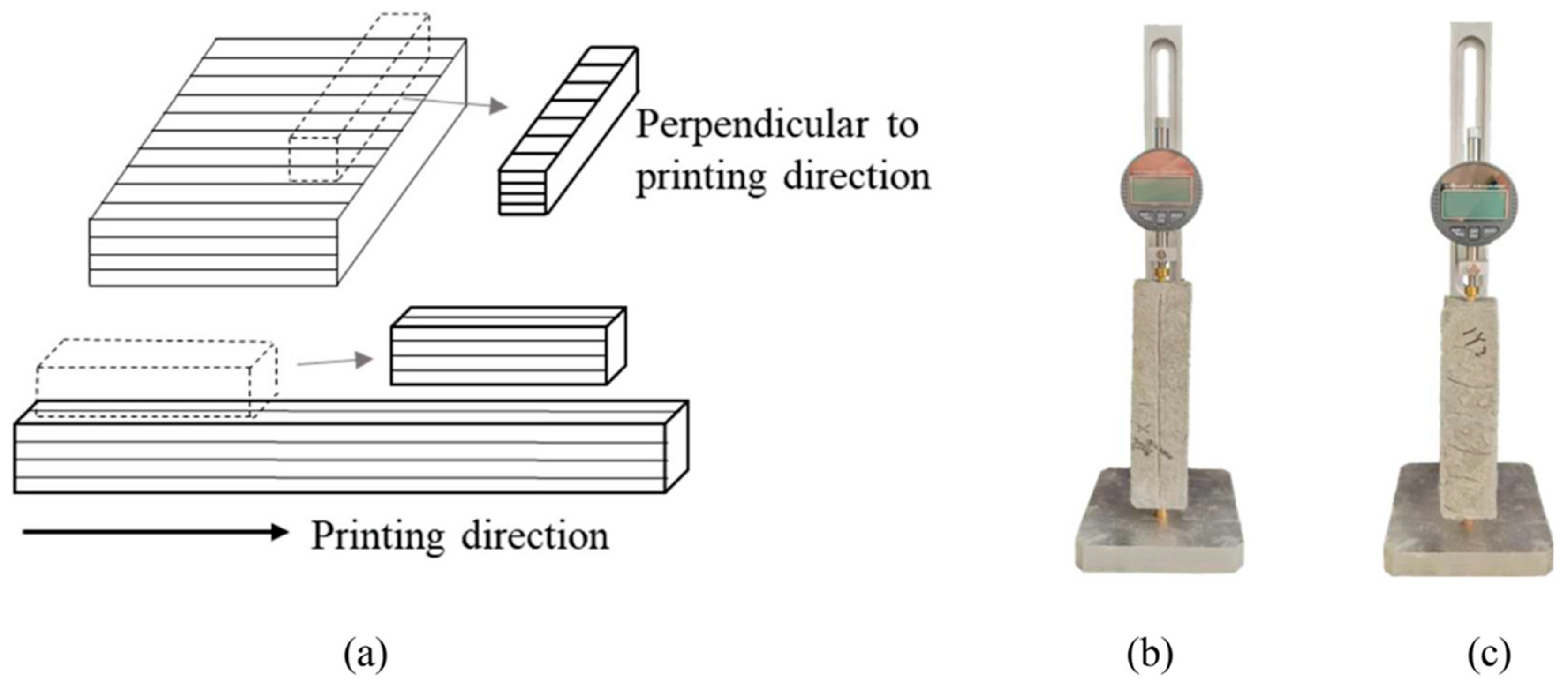
Three-dimensional-printed components are anisotropic, so it is necessary to test them in the x, y, and z directions [63]. In a study [64], the cast specimens were made in a cubic and rectangular prism shape to match the printed samples. Rectangular slabs measuring 1000 mm × 200 mm × 120 mm were printed for compressive strength tests and 500 mm × 200 mm × 180 mm for flexural strength tests. These were then allowed to cure for 28 days, so that full strength could be acquired. Once cured, the printed samples were cut and polished to the dimensions of the moulded samples. The resulting dimensions of the printed cut samples were 70.7 mm × 70.7 mm × 70.7 mm for the compressive test and 40 mm × 40 mm × 160 mm for the flexural test. The 3D-printed samples were loaded in all three directions, and the cast specimen was loaded in one direction, as it was isotropic. The loading direction for the compressive test can be seen in Figure 2, and the cutting and loading direction for the flexural test specimens can be seen in Figure 3. Tests were carried out on days at 1, 3, 7, and 28, to observe how the strength increased over time.

3.3. Shrinkage Test

In one study [39], the total shrinkage was measured. To measure the shrinkage of the concrete, specimens of 40 mm × 40 mm × 160 mm were made from cut printed elements 2 h after mixing. Copper heads are put 5 mm into the specimen to allow for the humidity data to be collected. The printed specimens were cured 5 h after printing and placed into a controlled indoor environment of 20 ± 1 °C and 60 ± 2 RH. To measure the length of the samples, digital comparators with an accuracy of 0.001 mm were used [39]. The shrinkage was tested in both the parallel and perpendicular direction to printing. Casted samples were also tested to allow for comparison. The initial length was taken at 24 h mark after the water was added, and measurements were taken every day in the first week, and then at the 10, 14, and 28-day mark. The specimen samples and digital length comparators are shown in Figure 4a–c below.

3.4. Interlayer Bond Strength Test

In one study [65], the interlayer bond strength was measured by applying uniaxial tension to printed specimens sized 50 mm × 25 mm × 30 mm. Notches of 5 mm depth were cut into the samples and then put under loading, as shown in Figure 5. To ensure that the specimen failed between the two layers, notches of 5mm depth were cut into the edges of the layer interface. Metal brackets were attached to each side of the sample using epoxy resin. A 1 mm/min displacement was the force applied to calculate the interlayer bond strength, and the failure displacement was noted. It was essential that the sample was aligned in the testing apparatus to ensure that eccentricities remained out of the equation [65].

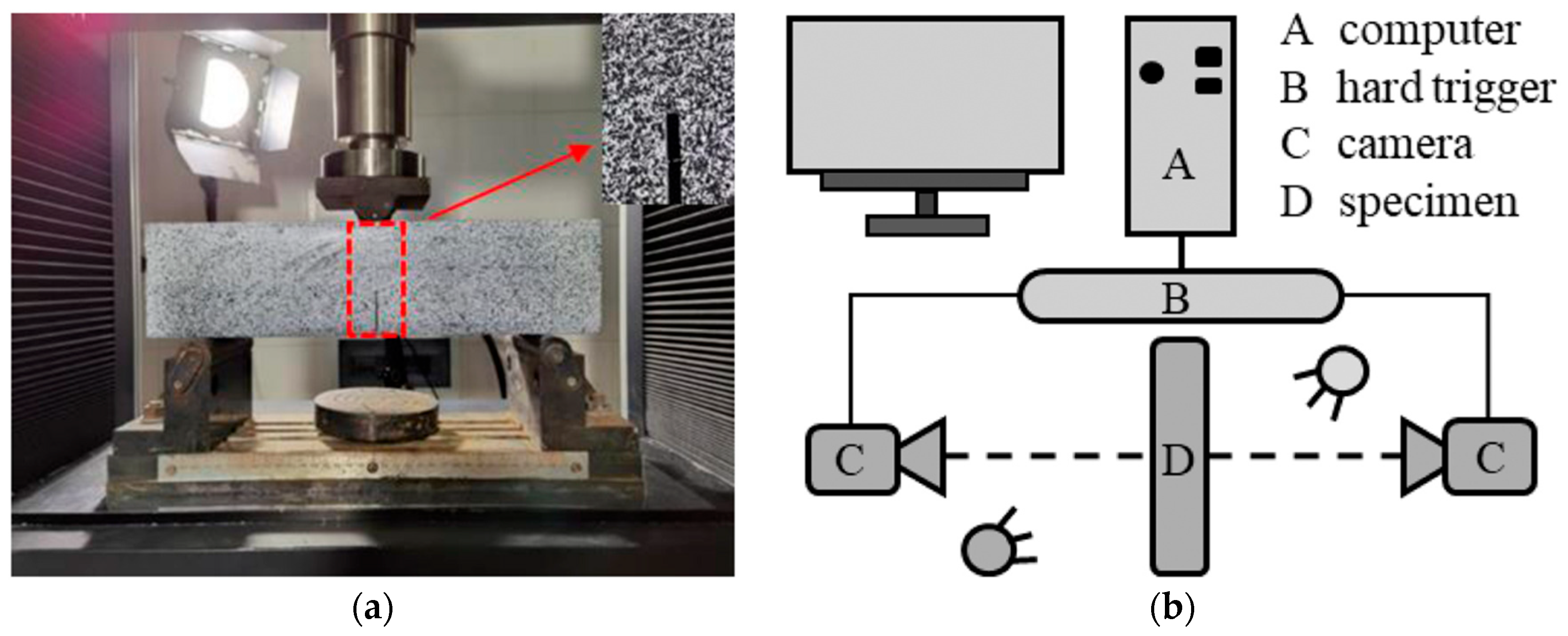
3.5. Fracture Energy Test

In one study [66], extensive research was conducted on fracture behaviour in PVA fibre-reinforced 3D-printed concrete. The following procedure was used to measure the fracture energy. A printed specimen was cut to 100 mm × 100 mm × 400 mm, and a cast specimen was made to the same size to compare results. A gap was cut at the mid-span of the sample with a standard ally-to-height ratio of 0.4, as shown in Figure 6. After cutting the surface, the specimen is painted black and white speckled. This process is done to allow precise tracking of cracking using Digital Image Correlation (DIC) technology (Figure 7a,b) [67]. The black-and-white speckle appearance provides a high-contrast surface, which is what the DIC system needs to detect and measure fine details of displacement and strain on the surface during the fracture of the specimen. The loading equipment used was a Shimadzu AGX-100 KN precision electronic universal testing machine, as shown in the experimental set-up in Figure 7. It applied displacement loading of 0.05 mm/min [66]. This procedure was performed in the directions x, y, and z for the printed samples and one direction for the casted samples. The DIC cameras captured how the samples deformed and images of the failure point.

3.6. Fluidity Test

To measure how the fibres affect the fluidity of the mix, a flow table test was carried out. The standards set in ASTM C230 [68] require the mortar being filled into a mould on a flow table, once the mould was filled it was removed and the mortar was subjected to 25 drops. The diameter recorded was then taken as the fluidity result [50]. The recommended flow is between 150 mm and 182 mm, according to a study done [50]. The test apparatus is shown in Figure 8.

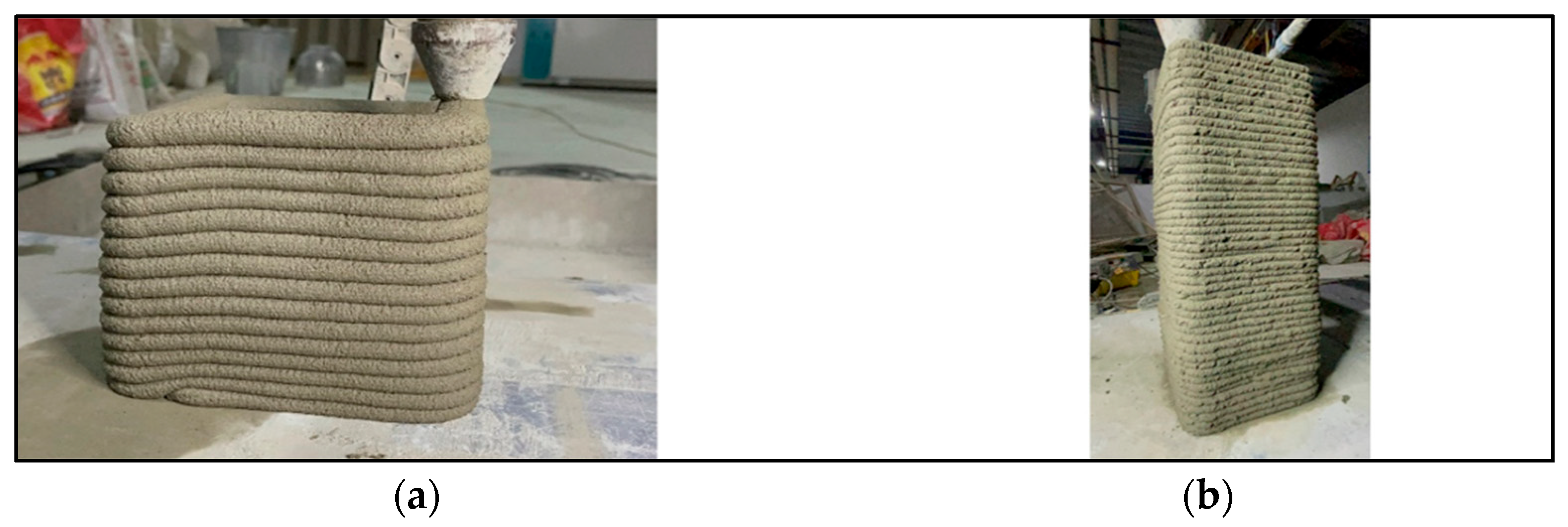
3.7. Buildability Test

To test the buildability, a 200 mm square was printed and the number of successive layers printed on top of one other before failure was measured (Figure 9). The number of layers achieved before failure was the measure of the mix’s buildability [50]. This test was done with a control mix with no fibres to observe the increase in buildability.

3.8. Extrudability Test

The measure the extrudability, a physical exam of the filament is performed (Figure 10). The average width was taken from 3 different locations along the filament. This average width was then taken as the extrudability indicator. The optimal extrudability had a smooth surface with no cracks or blockages, according to the study by Nasr, Duan [50].

3.9. Rheological Test

A Brookfield rheometer with a vane spindle of 30 mm × 15 mm in size within a beaker of 500 mL was used to test the rheological properties, plastic viscosity, dynamic yield stress, and static yield stress (Figure 11) [69]. Samples with different fibre dosages were used to compare the influence of fibres. A constant shearing rate of 0.1 s−1 was sustained for 3 min to measure the static yield stress [70]. The peak of the shear stress was taken as the static yield stress [71]. This process was repeated at intervals of 10 min till the 40 min mark after the water was added to dry powder [39]. To measure the dynamic stress and viscosity, the vane spindle rotation was linearly increased from 0 s−1 to 50 s−1 within 60 s, then decreased to 0 s−1 linearly in the 60 s after [72]. The Bingham equation, τ = τ 0 + η γ was used to fit the curve with decreasing shear rate from 50 s−1 to 0 s−1, where τ is shear stress, τ 0 is dynamic yield stress, η is plastic viscosity, and γ is shear rate [73]. Higher doses may interfere with the machine; if this is the case, the testing methods stated in Section 3.7, Section 3.8 and Section 3.9 can be used for evaluation of fresh properties.

4. Effects of Polypropylene Fibres in 3D-Printed Concrete

4.1. On Fresh State Properties
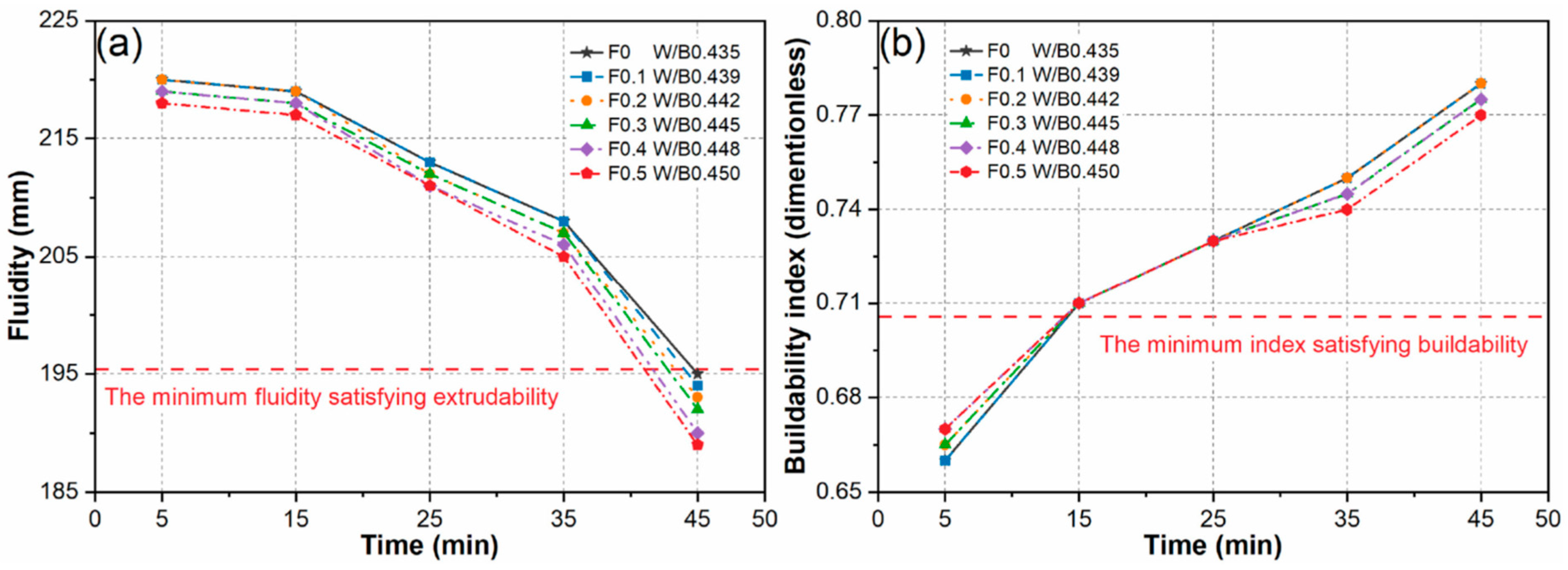
The key parameters to look at for the fresh-state properties of the concrete are buildability and flowability. The mixture needs to be extrudable and buildable, meaning that it should have the ability to flow through the nozzle without any blockages smoothly and have the required stiffness to be able to retain its shape after extrusion [65]. Polypropylene fibres reduce the fluidity of the geopolymer mortar but increase its buildability. This decrease in fluidity can be improved by adjusting the water-binder ratio [42].

4.1.1. Fluidity

Fluidity is responsible for the ability of the mixture to flow and be transferred from the mix container to the printing head [49]. In one study [42], the effect of fibres on fluidity with respect to time was studied for a geopolymer mortar mix. It was found that fluidity decreases with respect to time and that adding fibres decreases the fluidity marginally, as shown in Figure 12a. The rheological properties were also investigated in a study [39]. It was found that static yield stress increases with fibre dosage, as shown in Figure 13a. The static yield stress is required to initiate the flow [39]. A high value gives the mix good buildability, but a value that is too high will reduce the workability of the mix. In this study, all the fibre dosage mixes were printable.

4.1.2. Buildability

Buildability is responsible for keeping the structure stable directly after printing, so it is essential that this property is of strong value. The addition of fibres can help improve this value. Figure 12b shows how different fibre percentages and water-binder ratios affect the fluidity and buildability with respect to time [42]. The legend has “F” representing the fibre content and “W/B” representing the water-binder ratio. The buildability increased with fibre content from 5–15 min but then decreased from 25 min onwards. This is due to how the low yield stress mortar interacts with the fibres. It increases the yield stress, initially boosting the buildability [39]. However, over time, the workability loss from the fibre causes a decrease in buildability [75]. The graph shows that the optimal time for printing is 15–25 min after printing, as fluidity and buildability are both good values for printing [42].

4.1.3. Extrudability

Dynamic yield stress is one of the main factors responsible for extrudability [76]. It must be within a range that allows the concrete to flow and remain cohesive. There is a linear relationship between the dynamic yield stress and fibre dosage, as shown in Figure 13a. This is due to the entanglement of fibre, which slows down the recovery of flow [77]. Plastic viscosity describes how much the material resists flowing once it has started to move. As shown in Figure 13b, the plastic viscosity increases with fibre dosage, indicating that the extrudability is affected by the fibres [74]. A too-high plastic viscosity could cause the printer to clog. The dynamic yield stresses found for each fibre dosage in the study, as shown in Figure 13a, were all within the printable range for 3D-printed concrete.

4.2. Hardened State Properties

Polypropylene fibres significantly enhance the hardened state properties of the 3D-printed concrete. They enhance flexural strength, compressive strength, fracture energy, and crack resistance. The following discussion concerns the addition of fibre.

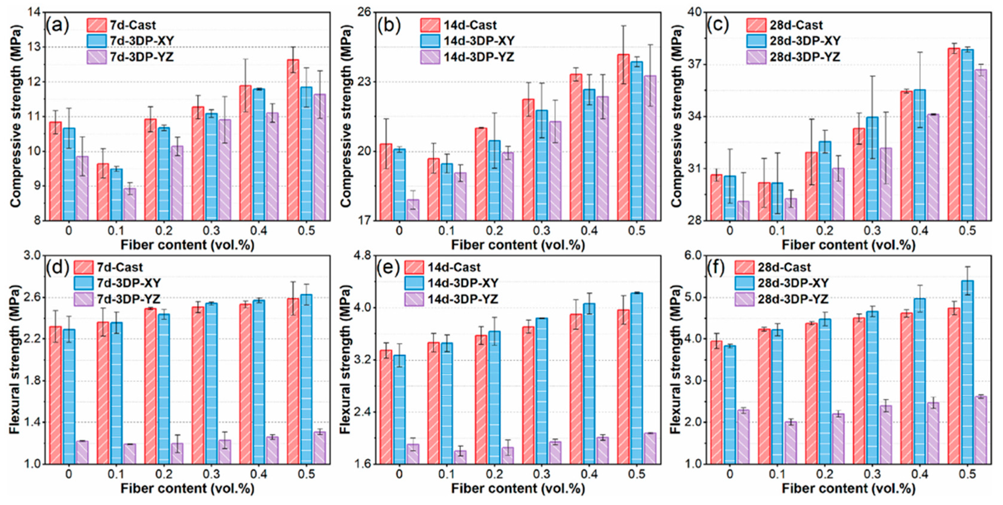
4.2.1. Flexural and Compressive Strength

The addition of fibres improves flexural and compressive strength. However, it experiences anisotropic behaviours as the fibres work best parallel to the print direction and are less effective in the perpendicular direction [42]. Figure 14 shows fibre dosage affects compressive and flexural strength at 7 days, 14 days, and 28 days after casting/printing. The difference between the strength in the casted specimens and the 3D-printed specimens in both the parallel (XY) and perpendicular (YZ) is also shown [42]. The compressive strength initially drops at 0.1% fibre content but then increases from 0.2% to 0.5%. The strength at 28 days for fibre content of 0.5% was 37.86 MPa in the XY-axis and 36.68 MPa in the YZ-axis, representing increases of 23.89% and 26.04%, respectively, when compared to the specimen with no fibres [42]. This indicates that the fibres enhance compressive strength, and the anisotropic behaviour is minimal in terms of compressive strength.
The anisotropic behaviour is much more apparent in the flexural strength, as shown in Figure 15. The flexural strength in the XY-axis is much higher than in the YZ-axis. This is because of the way the fibres are orientated. In the parallel (XY) direction, they are much more efficient at taking the load and bridging gaps [42]. It is also seen that the cast specimen provides the highest capacity up to 0.2% fibre dosage, but from 0.2–0.5%, the printed specimen in the XY-axis has the highest capacity. At 28 days, the flexural strength in the XY-axis and YZ-axis of the specimen with 0.5% fibre content was 5.39 MPa and 2.62 MPa, respectively. This resulted in a 40.94% increase in the XY-axis and 14.35% in the YZ-axis compared to the specimen with no fibres [42].
Interval time is a factor that affects the flexural and compressive strength of the concrete. It is the time between the deposition of successive printed layers. Figure 15 shows how the flexural and compressive strength can be affected by interval time. It is seen that as the interval time increases, the flexural and compressive strength decreases. This is because of the formation of cold joints, which causes a weak bond in the layers because the lower layer is partially set before the upper layer. From the results, it is best to keep the interval time below 30 min [42].

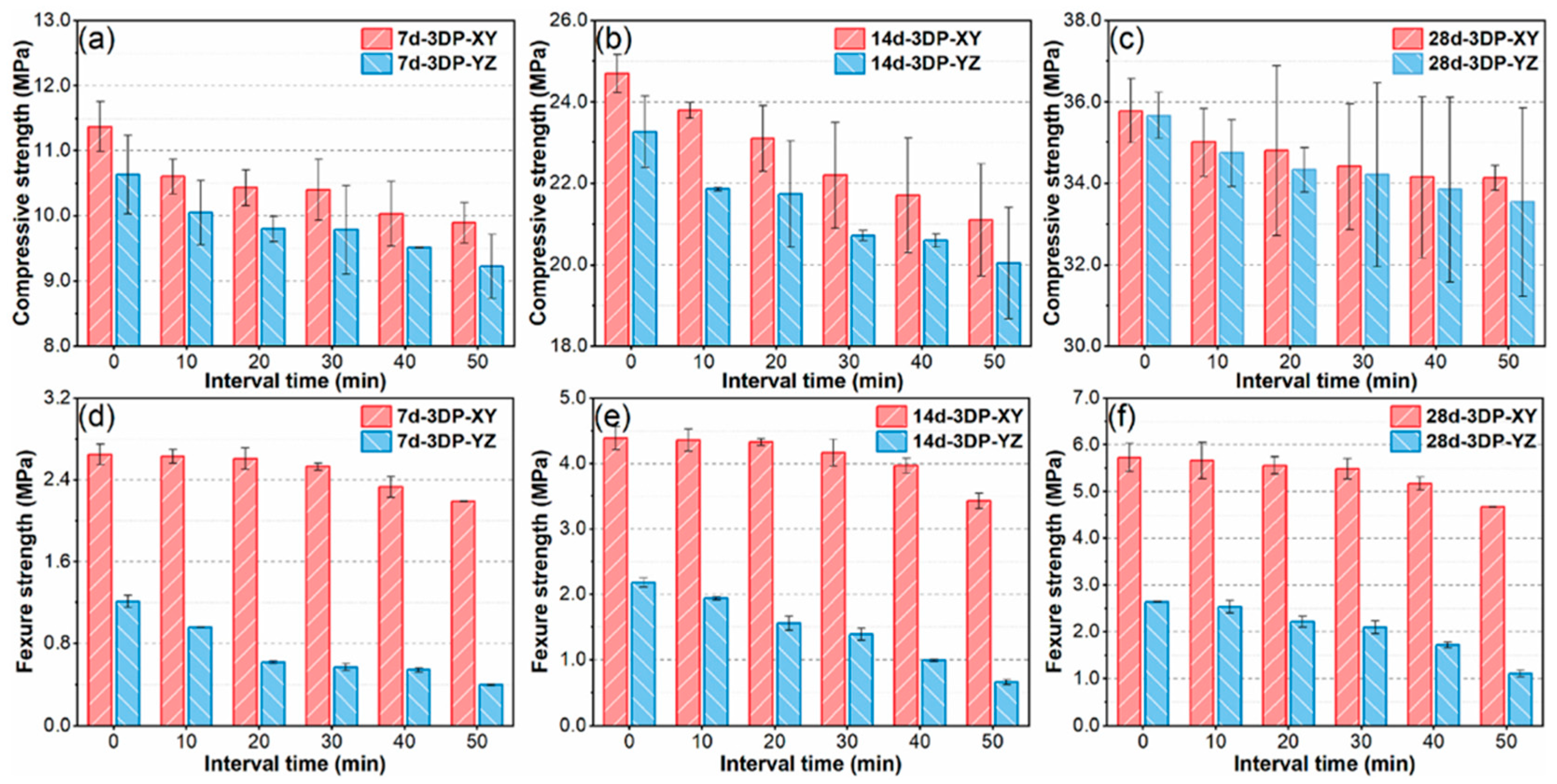
4.2.2. Interlayer Bonding
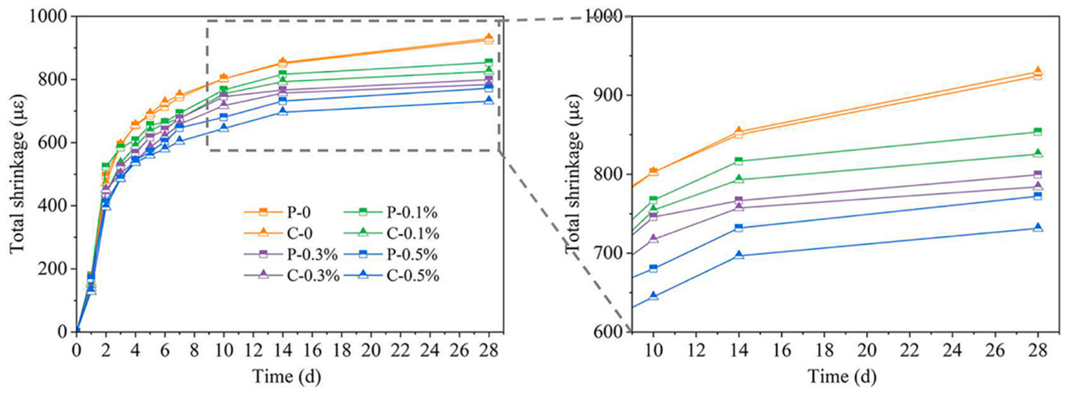
Interlayer bonding is the strength of the bond between successive printed layers. It can be seen in Figure 16 that there is a relationship between the fibre dosage and the interlayer strength. At first, it decreases at 0.1% fibre dosage, but then it increases from 0.2–0.5%. The increase in interlayer bonding strength can be due to the fibre’s bridging effect, which is when they span through the interlayer gaps and increase the overall bonding properties [42]. As is seen with the relationship between compressive and flexural stress with interval time, the same is seen with the interlayer bonding and interval time. As the interval time increases, the bonding decreases. The strength growth rate was highest at 30 min intervals, so the interval should be kept to less than 30 min [42].

4.2.3. Shrinkage

Drying shrinkage is a major issue in 3D-printed concrete, leading to cracking. It happens due to a high hydration level, leading to “plastic shrinkage, autogenous shrinkage, drying shrinkage, and cracking” [33]. Polypropylene fibres are added to mitigate these effects and prevent cracks from forming. The orientation of the fibres in the printing direction restricts the printed strips stress and strain, improving their tensile strength. When the concrete experiences shrinkage stress, the fibres can absorb a sizeable amount of that energy, reducing shrinkage effects [42]. Figure 17 shows the effect that the polypropylene fibres have on shrinkage. Printed and cast specimens were compared with a number of different fibre dosages, and the results indicate that as the fibre dosage was increased, the total shrinkage was reduced. Adding 0.5% fibre resulted in a 19.6% reduction in shrinkage compared to the specimen without fibres [39].

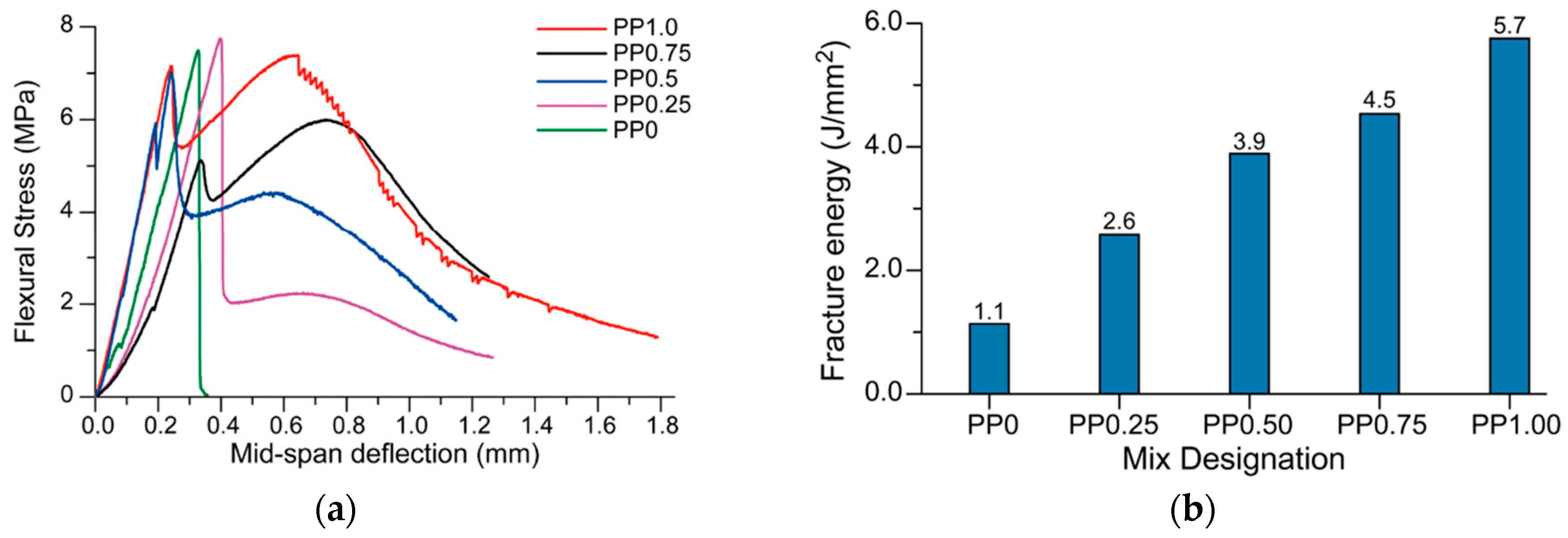
4.2.4. Fracture Energy and Deflection
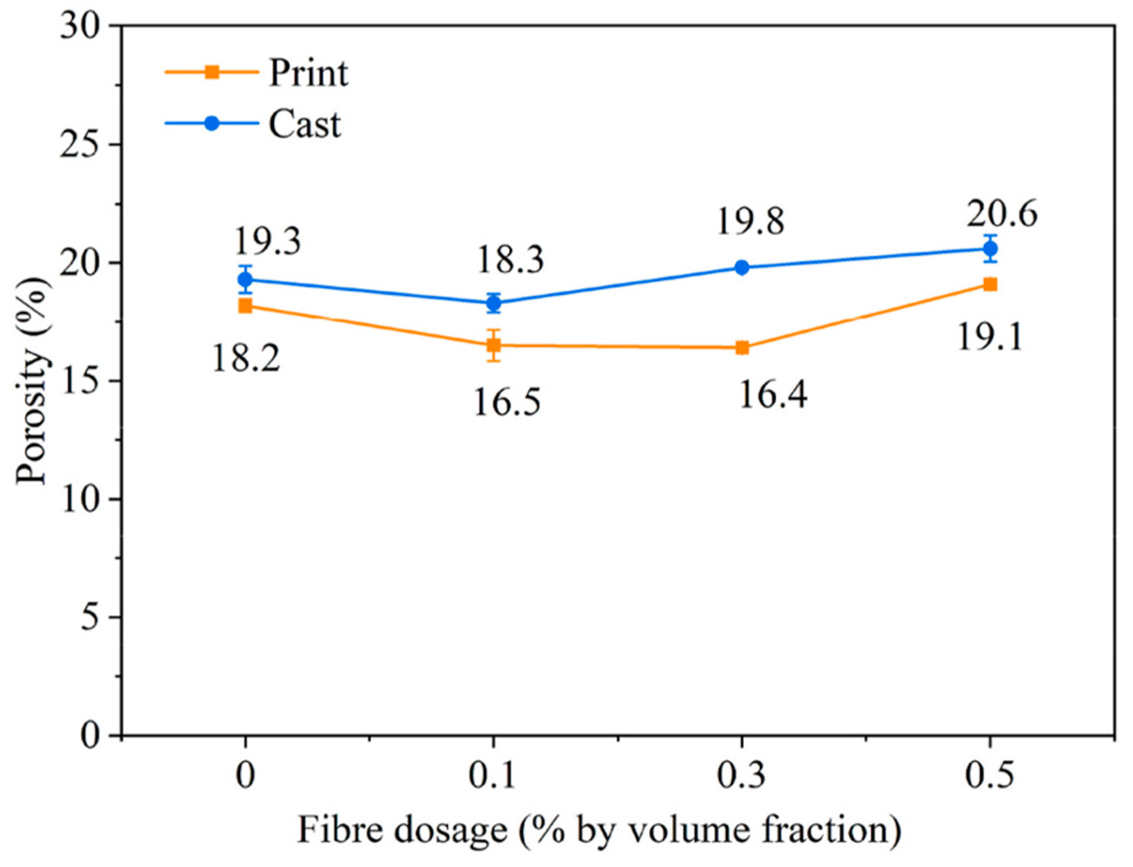
Adding polypropylene fibres improves the ductility of the material, as evident in the deflection and fracture energy tests. The polypropylene fibre’s bridging effect allows them to take the load when the concrete fails. A study [65] shows how the fibres in geopolymer mortar impact the fracture energy and deflection of the 3D-printed specimens, as shown in Figure 18 It can be seen in Figure 18a that the specimen with no fibres experiences a brittle failure. The specimens with 0.25% and 0.5% fibres experienced a phenomenon called deflection-softening, while the samples with 0.75% and 1% fibre showed behaviours of deflection-hardening. Figure 18b shows that the fracture energy increases as fibre dosage increases. This confirms the crack bridging theory and reaffirms the data in Figure 18a.

4.2.5. Porosity

Porosity is the presence of voids within the microstructure of a material. These voids come in a range of forms and sizes, starting with gel pores, which are very small (0.5–5 nm) within the cement hydrating product; capillary pores, which are slightly larger (5 nm–10 μm) that are formed during hydration stage; and entrapped voids, which are larger voids (>10 μm) that remain after the material’s placement and compaction [51]. The factors that affect the overall porosity in hardened concrete are as follows: “the type of cement, water-to-cement (w/c) ratio, incorporated additives and admixtures, degree of hydration, paste viscosity, coarse aggregate size and grading, duration and intensity of vibration during extrusion and compaction via overlay pressure, along with curing conditions” [78]. The inclusion of fibres increases the porosity of the concrete. The lower density of PP fibres (0.92 kg/m3) compared to the surrounding cement paste (~2150 kg/m3) can cause the fibres to appear as voids in microstructural analysis, so the apparent porosity may not be slightly increased. The reduced particle packing density and increased viscosity due to the fibres could also contribute to the increase in porosity. Including fibres caused an increase in porosity by 2.9% in the horizontal direction and 2.4% in the vertical direction [51]. These voids negatively impact compressive strength; however, the strength that polypropylene fibre offers in terms of ductility and resistance to shrinkage cracking can offset this decrease [79]. Air-entraining admixtures can potentially minimize these air voids [79]. In one study [39], the fibre’s effect on porosity was studied, and it was found that the porosity decreased at 0.1% fibres but then increased from 0.1% to 0.5%, as shown in Figure 19. This is due to the increased viscosity caused by the fibres and the lack of densification in the concrete.

4.3. Effect of PP Fibre Variables

Based on the foregoing discussion of individual performance parameters, a comprehensive summary of the effects of PP fibre incorporation in 3D-printed concrete is presented in Table 3. The incorporation of PP fibres exhibits significant improvements in multiple performance aspects, which are closely dependent on the fibre dosage, length, and printing parameters. At low dosages (0.1–0.3 vol%), PP fibres mainly enhance shape retention and green stability, while their effect on mechanical performance remains limited. With increasing fibre dosage up to approximately 0.5 vol%, the rheological properties are significantly optimized, as reflected in increased yield stress and improved thixotropy. Simultaneously, moderate improvements in compressive and flexural strength are observed, along with a noticeable reduction in shrinkage deformation. Further increasing the fibre content to 1.0–1.25 vol% leads to a transition from deflection-softening to deflection-hardening behaviour, accompanied by substantial enhancements in toughness and crack resistance, and maximum shrinkage reduction.
In terms of fibre geometry, 6 mm fibres consistently exhibit superior performance in enhancing flexural strength and ductility. Regarding printing process parameters, a smaller nozzle diameter (4–6 mm) and a relatively low printing speed (30–60 mm/s) contribute to improved print precision and mechanical performance due to better fibre alignment and reduced interlayer defects. Based on the overall performance evaluation, the optimal fibre configuration is recommended within the range of 0.5–1.0 vol% dosage and 6 mm length, combined with moderate printing speeds (40–60 mm/s) and a controlled nozzle diameter (4–6 mm), which enables a balanced improvement in rheology, mechanical strength, and dimensional stability of printed structures.

5. Gaps in Knowledge and Future Research

Polypropylene fibres in 3D-printed concrete are a relatively new research topic, resulting in numerous knowledge gaps. Some of the gaps in the research are as follows:
  • Most studies use a fixed fibre length, often neglecting the impact of variations in length or aspect ratio on fracture toughness, crack control, and workability. The influence of fibre alignment on anisotropic properties in the z-direction also remains underexplored. There is limited research on the effect of fibre length in areas such as its impact on crack propagation and fracture behaviour, as well as its influence on long-term durability and shrinkage. The papers researched in this review focused on limited fibre length and dosages, as no detailed variety in length was examined.
  • There is limited research on recycled fibres. However, some good research exists with positive results in a study [50] on the effect of recycled PP and PET fibres is available but still limited. Further research could be conducted in this area to confirm their results and to investigate the reduced drying shrinkage in recycled fibres compared to non-recycled fibres.
  • Existing literature offers limited insight into combining PP fibres with other fibres (e.g., steel, basalt, carbon). Hybrid systems may offer synergistic improvements in strength, ductility, and shrinkage resistance but require in-depth study to determine optimal configurations and dosages. Combining the two different fibres could enable the 3D-printed concrete to benefit from both. The 3DPC would obtain the strong mechanical properties from the steel and the substantial shrinkage and crack control properties that polypropylene provides. In this area, the dosage amounts and lengths of each fibre can be varied to determine the most effective one.
  • Although promising results have been reported using recycled PP and PET fibres, comprehensive life-cycle analyses and performance assessments (durability, bond strength, environmental aging) are lacking.
  • Studies largely focus on early-age strength and shrinkage. Long-term behaviour under various environmental conditions, including freeze–thaw cycles, carbonation, and chloride ingress, needs further evaluation.
  • Variability in testing methods (e.g., interlayer bonding strength, rheology, buildability) limits comparison across studies. Development of uniform testing standards is crucial for advancing this field.
  • Modelling the fibre–matrix interaction and incorporating AI or machine learning for mix optimisation is still in its beginnings, presenting an opportunity for predictive and efficient mix design frameworks.

6. Conclusions

This comprehensive review examines how incorporating polypropylene (PP) fibres can significantly enhance the performance of 3D-printed concrete, provided the mix design is carefully optimised. Three-dimensional printable concretes often rely on high cement content, which is mitigated by blending in supplementary cementitious materials (SCMs) such as silica fume, fly ash, and ground slag to improve sustainability and overall material properties. These SCM replacements reduce the cement content and carbon footprint while refining workability and strength development. When PP fibres are introduced into such mixes, further adjustments are necessary: lowering the water-to-binder ratio and using chemical admixtures (superplasticisers and set accelerators) help counteract the fibre-induced loss of fluidity. An optimal balance of binder composition, fibre volume, and admixture dosage must be struck to ensure the material remains extrudable and workable without sacrificing buildability or early strength. This careful mix tailoring enables the effective use of PP fibres in 3DPC, leveraging their benefits while maintaining print quality and sustainability.
In its fresh state, PP fibre reinforcement predominantly improves the rheological profile of the concrete, benefiting printing stability. The added fibres increase the static yield stress and plastic viscosity of the mix, which enhances shape retention (buildability) and enables stronger interlayer adhesion through fibre bridging, although they affect the flowability. Moderate fibre dosages (approximately 0.5–1.0% by volume) have been shown to significantly improve buildability and interlayer bond strength without critically compromising extrudability. Within this range, the fibres bond the layers together and resist layer deformation, leading to well-bonded, stable prints. Beyond an optimal content, however, rheology management becomes challenging. For example, at 1.5% fibre content, the mix exhibits substantially higher yield stresses and requires roughly 5–6 kg/m3 of superplasticiser to remain pumpable. Such high dosages, while possible, can introduce their own side effects (e.g., set retardation or segregation), underscoring the importance of balancing fibre content with admixture tuning. In practice, careful control of mix parameters ensures that PP fibres confer maximum benefits in their fresh state, increasing green strength and dimensional stability while avoiding nozzle clogging or collapse. The need for real-time rheological control and perhaps mix-on-demand approaches (e.g., inline addition of accelerators) is evident to maintain an adequate open time and smooth extrusion in fibre-rich 3DPC mixes. Overall, PP fibre integration in the fresh phase enhances layer cohesiveness and builds height, with a proper mix design allowing these advantages to be realized without compromising workability.
In the hardened state, PP fibres provide measurable gains in mechanical performance and cracking resistance for 3D-printed concrete, transforming a brittle printed matrix into a more ductile composite. The fibres act as micro-reinforcement bridging cracks, which elevates both compressive and flexural strength, especially when fibres are oriented parallel to the load direction (along print layers). Notably, incorporating as little as 0.5% PP fibre by volume can increase 28-day compressive strength by roughly 23–26% compared to unreinforced 3DPC, with reported strengths on the order of 37–38 MPa in printed elements. Improvements in flexural/tensile capacity are similarly observed; while the absolute gains are more modest than with steel fibre reinforcement, they are significant for a polymer fibre and contribute greatly to post-crack load bearing. More importantly, PP fibres dramatically mitigate shrinkage-related cracking: a 0.5% fibre dosage was shown to reduce total drying shrinkage by about 19.6% relative to a fibre-free mix. By absorbing internal stresses and restraining volumetric changes, the fibres prevent many micro-cracks from propagating, thereby enhancing long-term dimensional stability. As fibre dosage increases, the material sees a marked increase in ductility and energy absorption capacity—printed specimens that are unreinforced fail in a brittle manner, whereas those with ≥0.75% PP exhibit deflection-hardening behaviour, with higher fracture energy and the ability to sustain loads after cracking. This is explained by the greater toughness and resilience of the 3D-printed structure under load. These benefits do come with minor compromises: the inclusion of PP fibres tends to slightly increase the porosity of the hardened concrete due to their low specific gravity and the potential for entrapped voids around fibre filaments. Experiments have documented only a modest ~2–3% rise in porosity with typical fibre additions, which can marginally reduce the net compressive strength. However, the associated improvements in crack control, ductility, and load redistribution largely offset this strength penalty, as the fibre’s contribution to post-cracking resistance compensates for the small loss in initial matrix strength. PP fibre reinforcement yields a more robust hardened material, characterized by higher flexural strength, comparable or slightly improved compressive strength, significantly reduced shrinkage cracking, and enhanced toughness. In conclusion, using a nozzle of 4–6 mm, a layer height of 3–5 mm, and a print speed of 40–60 mm/s gives smooth, accurate layers and strong bonds between them. Adding 6 mm-long PP fibres at 0.5–1.0 vol% with the discussed printing settings strikes the best balance of flowability, strength, toughness, and dimensional stability. This literature study offers a valuable insight into the existing work in the area and highlights the understudied aspects, as outlined in the Section 5 above.

Author Contributions

Conceptualization, B.H. and M.K.; methodology, M.K.; software, B.H.; validation, B.H., W.S. and M.K.; formal analysis, W.S.; investigation, W.S.; resources, M.K.; data curation, B.H.; writing—original draft preparation, B.H.; writing—review and editing, W.S.; visualization, W.S.; supervision, M.K.; project administration, C.M.; funding acquisition, C.M. All authors have read and agreed to the published version of the manuscript.

Funding

This publication emanated from 2 separate projects. The first is funded by Construct Innovate Technology Centre and Harcourt Technologies Limited (HTL) (Grant Code: CISFC1-23_013). The second is funded by Ecocem Materials and the Science Foundation Ireland (SFI) Research Centre in Applied Geosciences hosted by UCD (iCRAG-Phase 2-Grant Code: 13/RC/2092_P2). The authors would like to express special gratitude to MDPI for fully waiving the APC.

Data Availability Statement

Not applicable.

Conflicts of Interest

The authors declare no conflicts of interest.

References

  1. Zhang, J.; Wang, J.; Dong, S.; Yu, X.; Han, B. A review of the current progress and application of 3D printed concrete. Compos. Part A Appl. Sci. Manuf. 2019, 125, 105533. [Google Scholar] [CrossRef]
  2. Xiao, J.; Ji, G.; Zhang, Y.; Ma, G.; Mechtcherine, V.; Pan, J.; Wang, L.; Ding, T.; Duan, Z.; Du, S. Large-scale 3D printing concrete technology: Current status and future opportunities. Cem. Concr. Compos. 2021, 122, 104115. [Google Scholar] [CrossRef]
  3. Khan, M.S.; Sanchez, F.; Zhou, H. 3-D printing of concrete: Beyond horizons. Cem. Concr. Res. 2020, 133, 106070. [Google Scholar] [CrossRef]
  4. Bhushan Jindal, B.; Jangra, P. 3D Printed Concrete: A comprehensive review of raw material’s properties, synthesis, performance, and potential field applications. Constr. Build. Mater. 2023, 387, 131614. [Google Scholar] [CrossRef]
  5. Alami, A.H.; Olabi, A.G.; Ayoub, M.; Aljaghoub, H.; Alasad, S.; Abdelkareem, M.A. 3D Concrete Printing: Recent Progress, Applications, Challenges, and Role in Achieving Sustainable Development Goals. Buildings 2023, 13, 924. [Google Scholar] [CrossRef]
  6. Xu, Z.; Zhang, D.; Li, H.; Sun, X.; Zhao, K.; Wang, Y. Effect of FA and GGBFS on compressive strength, rheology, and printing properties of cement-based 3D printing material. Constr. Build. Mater. 2022, 339, 127685. [Google Scholar] [CrossRef]
  7. Al-Noaimat, Y.A.; Chougan, M.; Al-kheetan, M.J.; Al-Mandhari, O.; Al-Saidi, W.; Al-Maqbali, M.; Al-Hosni, H.; Ghaffar, S.H. 3D printing of limestone-calcined clay cement: A review of its potential implementation in the construction industry. Results Eng. 2023, 18, 101115. [Google Scholar] [CrossRef]
  8. Varela, H.; Barluenga, G.; Perrot, A. Extrusion and structural build-up of 3D printing cement pastes with fly ash, nanoclays and VMAs. Cem. Concr. Compos. 2023, 142, 105217. [Google Scholar] [CrossRef]
  9. Klyuev, S.; Klyuev, A.; Fediuk, R.; Ageeva, M.; Fomina, E.; Amran, M.; Murali, G. Fresh and mechanical properties of low-cement mortars for 3D printing. Constr. Build. Mater. 2022, 338, 127644. [Google Scholar] [CrossRef]
  10. Marczyk, J.; Ziejewska, C.; Gądek, S.; Korniejenko, K.; Łach, M.; Góra, M.; Kurek, I.; Doğan-Sağlamtimur, N.; Hebda, M.; Szechyńska-Hebda, M. Hybrid Materials Based on Fly Ash, Metakaolin, and Cement for 3D Printing. Materials 2021, 14, 6874. [Google Scholar] [CrossRef]
  11. Arunothayan, A.R.; Nematollahi, B.; Ranade, R.; Bong, S.H.; Sanjayan, J.G.; Khayat, K.H. Fiber orientation effects on ultra-high performance concrete formed by 3D printing. Cem. Concr. Res. 2021, 143, 106384. [Google Scholar] [CrossRef]
  12. Li, H.; Addai-Nimoh, A.; Kreiger, E.; Khayat, K.H. Methodology to design eco-friendly fiber-reinforced concrete for 3D printing. Cem. Concr. Compos. 2024, 147, 105415. [Google Scholar] [CrossRef]
  13. Dai, P.; Lyu, Q.; Zong, M.; Zhu, P. Effect of waste plastic fibers on the printability and mechanical properties of 3D-printed cement mortar. J. Build. Eng. 2024, 83, 108439. [Google Scholar] [CrossRef]
  14. Luo, S.; Li, W.; Wang, D. Study on bending performance of 3D printed PVA fiber reinforced cement-based material. Constr. Build. Mater. 2024, 433, 136637. [Google Scholar] [CrossRef]
  15. Van Der Putten, J.; Rahul, A.V.; De Schutter, G.; Van Tittelboom, K. Development of 3D Printable Cementitious Composites with the Incorporation of Polypropylene Fibers. Materials 2021, 14, 4474. [Google Scholar] [CrossRef]
  16. Jin, Y.; Zhou, X.; Chen, M.; Zhao, Z.; Huang, Y.; Zhao, P.; Lu, L. High toughness 3D printed white Portland cement-based materials with glass fiber textile. Mater. Lett. 2022, 309, 131381. [Google Scholar] [CrossRef]
  17. Yan, Z.; Zeng, J.-J.; Zhuge, Y.; Liao, J.; Zhou, J.-K.; Ma, G. Compressive behavior of FRP-confined 3D printed ultra-high performance concrete cylinders. J. Build. Eng. 2024, 83, 108304. [Google Scholar] [CrossRef]
  18. Farina, I.; Fabbrocino, F.; Colangelo, F.; Feo, L.; Fraternali, F. Surface roughness effects on the reinforcement of cement mortars through 3D printed metallic fibers. Compos. Part B Eng. 2016, 99, 305–311. [Google Scholar] [CrossRef]
  19. Liu, Y.; Wang, L.; Cao, K.; Sun, L. Review on the Durability of Polypropylene Fibre-Reinforced Concrete. Adv. Civ. Eng. 2021, 2021, 6652077. [Google Scholar] [CrossRef]
  20. Lakshmi, A.; Pandit, P.; Bhagwat, Y.; Nayak, G. A Review on Efficiency of Polypropylene Fiber-Reinforced Concrete. In Sustainability Trends and Challenges in Civil Engineering; Springer: Singapore, 2022. [Google Scholar]
  21. Ahmad, J.; Burduhos-Nergis, D.D.; Arbili, M.M.; Alogla, S.M.; Majdi, A.; Deifalla, A.F. A Review on Failure Modes and Cracking Behaviors of Polypropylene Fibers Reinforced Concrete. Buildings 2022, 12, 1951. [Google Scholar] [CrossRef]
  22. Jiang, Q.; Liu, Q.; Wu, S.; Zheng, H.; Sun, W. Modification effect of nanosilica and polypropylene fiber for extrusion-based 3D printing concrete: Printability and mechanical anisotropy. Addit. Manuf. 2022, 56, 102944. [Google Scholar] [CrossRef]
  23. Liu, Q.; Jiang, Q.; Zhou, Z.; Xin, J.; Huang, M. The printable and hardened properties of nano-calcium carbonate with modified polypropylene fibers for cement-based 3D printing. Constr. Build. Mater. 2023, 369, 130594. [Google Scholar] [CrossRef]
  24. Ibrahim, K.A.; van Zijl, G.P.A.G.; Babafemi, A.J. Comparative studies of LC3- and fly ash-based blended binders in fibre-reinforced printed concrete (FRPC): Rheological and quasi-static mechanical characteristics. J. Build. Eng. 2023, 80, 108016. [Google Scholar] [CrossRef]
  25. Kurda, R.; de Brito, J.; Silvestre, J.D. Carbonation of concrete made with high amount of fly ash and recycled concrete aggregates for utilization of CO2. J. CO2 Util. 2019, 29, 12–19. [Google Scholar] [CrossRef]
  26. Aslani, F.; Zhang, Y. Sustainable 3D printed concrete structures using high-quality secondary raw materials. In Sustainable Concrete Materials and Structures; Woodhead Publishing: Cambridge, UK, 2024; pp. 399–443. [Google Scholar]
  27. Yuan, Q.; Zhou, D.; Li, B.; Huang, H.; Shi, C. Effect of mineral admixtures on the structural build-up of cement paste. Constr. Build. Mater. 2018, 160, 117–126. [Google Scholar] [CrossRef]
  28. Panda, B.; Tan, M.J. Rheological behavior of high volume fly ash mixtures containing micro silica for digital construction application. Mater. Lett. 2019, 237, 348–351. [Google Scholar] [CrossRef]
  29. Dey, D.; Srinivas, D.; Panda, B.; Suraneni, P.; Sitharam, T.G. Use of industrial waste materials for 3D printing of sustainable concrete: A review. J. Clean. Prod. 2022, 340, 130749. [Google Scholar] [CrossRef]
  30. Zhang, Y.; Zhang, Y.; Liu, G.; Yang, Y.; Wu, M.; Pang, B. Fresh properties of a novel 3D printing concrete ink. Constr. Build. Mater. 2018, 174, 263–271. [Google Scholar] [CrossRef]
  31. Wang, B.; Zhai, M.; Yao, X.; Wu, Q.; Yang, M.; Wang, X.; Huang, J.; Zhao, H. Printable and Mechanical Performance of 3D Printed Concrete Employing Multiple Industrial Wastes. Buildings 2022, 12, 374. [Google Scholar] [CrossRef]
  32. Wongkornchaowalit, N.; Lertchirakarn, V. Setting Time and Flowability of Accelerated Portland Cement Mixed with Polycarboxylate Superplasticizer. J. Endod. 2011, 37, 387–389. [Google Scholar] [CrossRef]
  33. Dilawar Riaz, R.; Usman, M.; Ali, A.; Majid, U.; Faizan, M.; Jalil Malik, U. Inclusive characterization of 3D printed concrete (3DPC) in additive manufacturing: A detailed review. Constr. Build. Mater. 2023, 394, 132229. [Google Scholar] [CrossRef]
  34. Chandra, S.; Björnström, J. Influence of superplasticizer type and dosage on the slump loss of Portland cement mortars—Part II. Cem. Concr. Res. 2002, 32, 1613–1619. [Google Scholar] [CrossRef]
  35. Qian, Y.; De Schutter, G. Different Effects of NSF and PCE Superplasticizer on Adsorption, Dynamic Yield Stress and Thixotropy of Cement Pastes. Materials 2018, 11, 695. [Google Scholar] [CrossRef] [PubMed]
  36. Long, W.-J.; Tao, J.-L.; Lin, C.; Gu, Y.-c.; Mei, L.; Duan, H.-B.; Xing, F. Rheology and buildability of sustainable cement-based composites containing micro-crystalline cellulose for 3D-printing. J. Clean. Prod. 2019, 239, 118054. [Google Scholar] [CrossRef]
  37. Hou, S.; Duan, Z.; Xiao, J.; Ye, J. A review of 3D printed concrete: Performance requirements, testing measurements and mix design. Constr. Build. Mater. 2021, 273, 121745. [Google Scholar] [CrossRef]
  38. Xu, J.; Chen, M.; Zhao, Z.; Li, L.; Wang, S.; Huang, Y.; Zhao, P.; Gong, C.; Lu, L.; Cheng, X. Printability and efflorescence control of admixtures modified 3D printed white Portland cement-based materials based on the response surface methodology. J. Build. Eng. 2021, 38, 102208. [Google Scholar] [CrossRef]
  39. Ma, L.; Zhang, Q.; Lombois-Burger, H.; Jia, Z.; Zhang, Z.; Niu, G.; Zhang, Y. Pore structure, internal relative humidity, and fiber orientation of 3D printed concrete with polypropylene fiber and their relation with shrinkage. J. Build. Eng. 2022, 61, 105250. [Google Scholar] [CrossRef]
  40. Zhou, Y.; Jiang, D.; Sharma, R.; Xie, Y.M.; Singh, A. Enhancement of 3D printed cementitious composite by short fibers: A review. Constr. Build. Mater. 2023, 362, 129763. [Google Scholar] [CrossRef]
  41. Warsi, S.B.F.; Panda, B.; Biswas, P. Exploring fibre addition methods and mechanical properties of fibre-reinforced 3D printed concrete: A review. Dev. Built Environ. 2023, 16, 100295. [Google Scholar] [CrossRef]
  42. Liu, X.; Hu, J.; Guo, X. Printability and interlayer bonding property of 3D printed fiber reinforced geopolymer (3DP-FRG). J. Build. Eng. 2024, 87, 109060. [Google Scholar] [CrossRef]
  43. Ding, T.; Xiao, J.; Zou, S.; Yu, J. Flexural properties of 3D printed fibre-reinforced concrete with recycled sand. Constr. Build. Mater. 2021, 288, 123077. [Google Scholar] [CrossRef]
  44. Ogura, H.; Nerella, V.N.; Mechtcherine, V. Developing and Testing of Strain-Hardening Cement-Based Composites (SHCC) in the Context of 3D-Printing. Materials 2018, 11, 1375. [Google Scholar] [CrossRef]
  45. Bos, F.P.; Bosco, E.; Salet, T.A.M. Ductility of 3D printed concrete reinforced with short straight steel fibers. Virtual Phys. Prototyp. 2018, 14, 160–174. [Google Scholar] [CrossRef]
  46. Ding, T.; Xiao, J.; Zou, S.; Zhou, X. Anisotropic behavior in bending of 3D printed concrete reinforced with fibers. Compos. Struct. 2020, 254, 112808. [Google Scholar] [CrossRef]
  47. Kumar Devalla, T.; Srinivas, D.; Panda, B.; Sitharam, T.G. Investigation on the flexural and tensile performance of 3D printable cementitious mixtures considering the effect of fiber distribution. Mater. Today Proc. 2023. [Google Scholar] [CrossRef]
  48. Liu, J.; Li, S.; Fox, K.; Tran, P. 3D concrete printing of bioinspired Bouligand structure: A study on impact resistance. Addit. Manuf. 2022, 50, 102544. [Google Scholar] [CrossRef]
  49. Ma, W.; Wang, G.; Zhou, Y.; Xu, Q.; Dai, Y. Polyacrylonitrile fiber reinforced 3D printed concrete: Effects of fiber length and content. J. Build. Eng. 2024, 97, 110869. [Google Scholar] [CrossRef]
  50. Nasr, A.; Duan, Z.; Singh, A.; Yang, M.; Zou, S.; Arab, M.A.E.-S. Enhancing mechanical properties of 3D printed cementitious composites utilizing hybrid recycled PP and PET fibers. Constr. Build. Mater. 2024, 455, 139179. [Google Scholar] [CrossRef]
  51. van den Heever, M.; du Plessis, A.; Kruger, J.; van Zijl, G. Evaluating the effects of porosity on the mechanical properties of extrusion-based 3D printed concrete. Cem. Concr. Res. 2022, 153, 106695. [Google Scholar] [CrossRef]
  52. Yao, Y.; Bu, D.; Yu, J.; Shao, L.; Feng, P.; Lu, C.; Wang, J. Flexural behavior of textile reinforced 3D printed concrete under quasi-static and dynamic impact loads. Case Stud. Constr. Mater. 2024, 21, e03645. [Google Scholar] [CrossRef]
  53. Zeng, J.-J.; Hu, X.; Sun, H.-Q.; Liu, Y.; Chen, W.-J.; Zhuge, Y. Triaxial compressive behavior of 3D printed PE fiber-reinforced ultra-high performance concrete. Cem. Concr. Compos. 2025, 155, 105816. [Google Scholar] [CrossRef]
  54. Skibicki, S.; Dvořák, R.; Pazdera, L.; Topolář, L.; Kocáb, D.; Alexa, M.; Cendrowski, K.; Hoffmann, M. Anisotropic mechanical properties of 3D printed mortar determined by standard flexural and compression test and acoustic emission. Constr. Build. Mater. 2024, 452, 138957. [Google Scholar] [CrossRef]
  55. David, M.; Freund, N.; Dröder, K.; Lowke, D. The effects of nozzle diameter and length on the resulting strand properties for shotcrete 3D printing. Mater. Struct. 2023, 56, 157. [Google Scholar] [CrossRef]
  56. Khan, S.A.; Ilcan, H.; Imran, R.; Aminipour, E.; Şahin, O.; Al Rashid, A.; Şahmaran, M.; Koç, M. The impact of nozzle diameter and printing speed on geopolymer-based 3D-Printed concrete structures: Numerical modeling and experimental validation. Results Eng. 2024, 21, 101864. [Google Scholar] [CrossRef]
  57. Shahzad, Q.; Abbas, N.; Akbar, M.; Sabi, E.; Thomas, B.S.; Arshid, M.U. Influence of print speed and nozzle diameter on the fiber alignment in 3D printed ultra-high-performance concrete. Front. Mater. 2024, 11, 1355647. [Google Scholar] [CrossRef]
  58. Nair, S.A.O.; Tripathi, A.; Neithalath, N. Examining layer height effects on the flexural and fracture response of plain and fiber-reinforced 3D-printed beams. Cem. Concr. Compos. 2021, 124, 104254. [Google Scholar] [CrossRef]
  59. Surehali, S.; Tripathi, A.; Nimbalkar, A.S.; Neithalath, N. Anisotropic chloride transport in 3D printed concrete and its dependence on layer height and interface types. Addit. Manuf. 2023, 62, 103405. [Google Scholar] [CrossRef]
  60. Zhang, N.; Sanjayan, J. Extrusion nozzle design and print parameter selections for 3D concrete printing. Cem. Concr. Compos. 2023, 137, 104939. [Google Scholar] [CrossRef]
  61. Zhang, H.; Wang, J.; Liu, Y.; Zhang, X.; Zhao, Z. Effect of processing parameters on the printing quality of 3D printed composite cement-based materials. Mater. Lett. 2022, 308, 131271. [Google Scholar] [CrossRef]
  62. Zhao, Y.; Yang, G.; Zhu, L.; Ding, Y.; Guan, X.; Wu, X.; Yang, Z. Effects of rheological properties and printing speed on molding accuracy of 3D printing basalt fiber cementitious materials. J. Mater. Res. Technol. 2022, 21, 3462–3475. [Google Scholar] [CrossRef]
  63. Wolfs, R.J.M.; Bos, F.P.; Salet, T.A.M. Hardened properties of 3D printed concrete: The influence of process parameters on interlayer adhesion. Cem. Concr. Res. 2019, 119, 132–140. [Google Scholar] [CrossRef]
  64. Sun, X.; Zhou, J.; Wang, Q.; Shi, J.; Wang, H. PVA fibre reinforced high-strength cementitious composite for 3D printing: Mechanical properties and durability. Addit. Manuf. 2022, 49, 102500. [Google Scholar] [CrossRef]
  65. Nematollahi, B.; Vijay, P.; Sanjayan, J.; Nazari, A.; Xia, M.; Naidu Nerella, V.; Mechtcherine, V. Effect of Polypropylene Fibre Addition on Properties of Geopolymers Made by 3D Printing for Digital Construction. Materials 2018, 11, 2352. [Google Scholar] [CrossRef] [PubMed]
  66. Liu, B.; Chen, Y.; Li, D.; Wang, Y.; Geng, S.; Qian, K. Study on the fracture behavior and anisotropy of 3D-printing PVA fiber-reinforced concrete. Constr. Build. Mater. 2024, 447, 138051. [Google Scholar] [CrossRef]
  67. Chen, Y.; Wei, J.; Huang, H.; Jin, W.; Yu, Q. Application of 3D-DIC to characterize the effect of aggregate size and volume on non-uniform shrinkage strain distribution in concrete. Cem. Concr. Compos. 2018, 86, 178–189. [Google Scholar] [CrossRef]
  68. C230/C230M; Standard Specification for Flow Table for Use in Tests of Hydraulic Cement. ASTM (American Society for Testing and Materials): West Conshohocken, PA, USA, 2021.
  69. Benaicha, M.; Jalbaud, O.; Hafidi Alaoui, A.; Burtschell, Y. Marsh cone coupled to a plexiglas horizontal channel: Rheological characterization of cement grout. Flow Meas. Instrum. 2015, 45, 126–134. [Google Scholar] [CrossRef]
  70. Panda, B.; Singh, G.V.P.B.; Unluer, C.; Tan, M.J. Synthesis and characterization of one-part geopolymers for extrusion based 3D concrete printing. J. Clean. Prod. 2019, 220, 610–619. [Google Scholar] [CrossRef]
  71. Rahul, A.V.; Santhanam, M.; Meena, H.; Ghani, Z. 3D printable concrete: Mixture design and test methods. Cem. Concr. Compos. 2019, 97, 13–23. [Google Scholar] [CrossRef]
  72. Zhang, Y.; Zhang, Y.; She, W.; Yang, L.; Liu, G.; Yang, Y. Rheological and harden properties of the high-thixotropy 3D printing concrete. Constr. Build. Mater. 2019, 201, 278–285. [Google Scholar] [CrossRef]
  73. Chen, M.; Yang, L.; Zheng, Y.; Huang, Y.; Li, L.; Zhao, P.; Wang, S.; Lu, L.; Cheng, X. Yield stress and thixotropy control of 3D-printed calcium sulfoaluminate cement composites with metakaolin related to structural build-up. Constr. Build. Mater. 2020, 252, 119090. [Google Scholar] [CrossRef]
  74. Tran, M.V.; Cu, Y.T.H.; Le, C.V.H. Rheology and shrinkage of concrete using polypropylene fiber for 3D concrete printing. J. Build. Eng. 2021, 44, 103400. [Google Scholar] [CrossRef]
  75. Sultangaliyeva, F.; Carré, H.; La Borderie, C.; Zuo, W.; Keita, E.; Roussel, N. Influence of flexible fibers on the yield stress of fresh cement pastes and mortars. Cem. Concr. Res. 2020, 138, 106221. [Google Scholar] [CrossRef]
  76. Alghamdi, H.; Nair, S.A.O.; Neithalath, N. Insights into material design, extrusion rheology, and properties of 3D-printable alkali-activated fly ash-based binders. Mater. Des. 2019, 167, 107634. [Google Scholar] [CrossRef]
  77. Wang, W.; Shen, A.; Lyu, Z.; He, Z.; Nguyen, K.T.Q. Fresh and rheological characteristics of fiber reinforced concrete—A review. Constr. Build. Mater. 2021, 296, 123734. [Google Scholar] [CrossRef]
  78. Aïtcin, P.C. Entrained air in concrete: Rheology and freezing resistance. In Science and Technology of Concrete Admixtures; Woodhead Publishing: Cambridge, UK, 2015; pp. 87–94. [Google Scholar]
  79. Aly, T.; Sanjayan, J.G.; Collins, F. Effect of polypropylene fibers on shrinkage and cracking of concretes. Mater. Struct. 2008, 41, 1741–1753. [Google Scholar] [CrossRef]
Figure 1. The process of 3D concrete printing (modified from [5]).
Jcs 09 00292 g001
Figure 2. Loading directions for compressive strength test. Reprinted with permission from [64].
Jcs 09 00292 g002
Figure 3. Cutting and loading directions for flexural test: (a) Cutting direction; (b) Prism cut along the x-axis and loaded from z- and y-directions; (c) Prism cut along the y-axis and loaded from z- and x-directions; (d) Prism cut along the z-axis and loaded from x- and y-directions. Reprinted with permission from [64].
Jcs 09 00292 g003
Figure 4. Shrinkage measurement: (a) Cutting specimens from 3D-printed elements; (b) Length test parallel to printing direction; (c) Length test perpendicular to printing direction. Reprinted with permission from [39].
Jcs 09 00292 g004
Figure 5. Interlayer bond strength test [65].
Jcs 09 00292 g005
Figure 6. Specimen dimensions of notched beam. Reprinted with permission from [66].
Jcs 09 00292 g006
Figure 7. Fracture test: (a) Test set up; (b) Schematic diagram of DIC. Reprinted with permission from [66].
Jcs 09 00292 g007
Figure 8. Flow table test. Reprinted with permission from [50].
Jcs 09 00292 g008
Figure 9. (a) Buildability test for control. (b) Buildability test for fibre-induced concrete. Reprinted with permission from [50].
Jcs 09 00292 g009
Figure 10. (a) Extrudability test for control. (b) Extrudability test for fibre induced concrete. Reprinted with permission from [50].
Jcs 09 00292 g010
Figure 11. Brookfield rheometer. Reprinted with permission from [69].
Jcs 09 00292 g011
Figure 12. Geopolymer mortar: (a) Effect of fibre on fluidity; (b) Effect of fibre buildability index. Reprinted with permission from [42].
Jcs 09 00292 g012
Figure 13. Fresh properties: (a) Dynamic yield stress versus fibre dosage; (b) Plastic viscosity versus fibre dosage. Data adapted from [74].
Jcs 09 00292 g013
Figure 14. Effect of fibre content on anisotropic compressive strength and flexural strength: (ac) Compressive strength at 7, 14, and 28 days in XY and YZ directions; (df) Flexural strength at 7, 14, and 28 days in XY and YZ directions. Reprinted with permission from [42].
Jcs 09 00292 g014
Figure 15. Effect of interval time on anisotropic compressive strength and flexural strength: (ac) Compressive strength at 7, 14, and 28 days in XY and YZ directions; (df) Flexural strength at 7, 14, and 28 days in XY and YZ directions. Reprinted with permission from [42].
Jcs 09 00292 g015
Figure 16. Effect of fibre content and interval time on interlayer bonding strength: (a) Fibre content; (b) Interval time. Reprinted with permission from [42].
Jcs 09 00292 g016
Figure 17. Comparison of shrinkage in printed and cast specimens with different fibre dosages. Reprinted with permission from [39].
Jcs 09 00292 g017
Figure 18. (a) Flexural stress versus mid-span deflection. (b) Fracture energy values [65].
Jcs 09 00292 g018
Figure 19. The porosity of concretes with different dosages of PP fibre. Reprinted with permission from [39].
Jcs 09 00292 g019
Table 1. Fibre analysis.
Fibre TypeTensile Strength (MPa)Youngs Modulus (GPa)Elongation (%)Specific GravityRef.
PP fibres310–7603.45–4.9150.90–0.91[40]
Polyethylene200–300530.96[40]
Steel fibres>1000150–180-7.8[40]
Table 2. Mixes from the literature review.
MixCementFASFWaterW/BSandSPVMAFibreMKRLPLC2GypsumGGBSClayUnitsRef.
M11000--3500.3510000.701.280.00%------(g)[46]
M21000--3500.3510000.711.28PE 0.25%------
M31000--3500.3510000.731.28PE 0.50%------
M41000--3500.3510001.121.28PE 1.00%------
M51000--3500.3510001.981.28PE 1.40%------
FA521161812350.3112297.642.29PP 1.00%------(kg/m3)[24]
LC2382--3440.4512297.642.29PP 1.00%--343.738.2--
C962-1072990.2810683.201.070.00%------(kg/m3)[47]
F0.5957-1062980.2810633.191.06Steel 0.50%------
F1.0953-1062960.2810583.181.06Steel 1.00%------
PnGPC 0.45-0.25-0.2610.012-0.00%----0.3-By weight of binder[48]
PnFGPC 0.45-0.25-0.2610.012-Steel 0.055%----0.3-
F0.0%697-60.62270.312131.290.380.00%------(kg/m3)[39]
F0.1%697-60.62270.312131.290.38PP 0.1%------
F0.3%697-60.62270.312131.290.38PP 0.3%------
F0.5%697-60.62270.312131.290.38PP 0.5%------
B00.9 PC
0.1 SAC
-0.1-0.310.01-0.00%0.020.1----By ratio to sand[49]
C10.9 PC
0.1 SAC
-0.1-0.310.01-PAN 0.10%0.020.1----
C20.9 PC
0.1 SAC
-0.1-0.310.01-PAN 0.20%0.020.1----
C30.9 PC
0.1 SAC
-0.1-0.310.01-PAN 0.30%0.020.1----
C40.9 PC
0.1 SAC
-0.1-0.310.01-PAN 0.40%0.020.1----
PP 0.3%850--2550.312755.951.088PP 0.3%------(kg/m3)[50]
PP 0.5%850--2550.312755.951.088PP 0.5%------
PP 1.0%850--2550.312755.951.088PP 1.0%------
PP 1.5%850--2550.312755.951.088PP 1.5%------
PET 0.3%850--2550.312755.951.088PET 0.3%------
PET 0.5%850--2550.312755.951.088PET 0.5%------
PET 1.0%850--2550.312755.951.088PET 1.0%------
PET 1.5%850--2550.312755.951.088PET 1.5%------
0.2PP +
0.8PET
850--2550.312755.951.0880.2PP +
0.8PET
------
0.4PP +
0.6PET
850--2550.312755.951.0880.4PP +
0.6PET
------
0.6PP +
0.4PET
850--2550.312755.951.0880.6PP +
0.4PET
------
0.8PP +
0.2PET
850--2550.312755.951.0880.8PP +
0.2PET
------
Mix56216281.42560.321144 Malmesbury4.92.4PP 1.00%------(kg/m3)[51]
Mix0.45 PC
0.05 SAC
0.40.1-0.260.280.01050.003%PVA 1.82%-----0.0035By mass ratio to cementitious material[52]
Mix8100.14202SF
450SP
2040.2066510.14-PE 0.5%------(kg/m3)[53]
Mix 1560160802400.3---0.00%------(kg/m3)[54]
Mix 2560160802400.3---Polye×
3 kg/m3
------
Table 3. PP fibre performance summary.
PP Fibre Content (vol.%)Fibre Length (mm)Optimal Printing
Parameter
Fresh State PerformanceMechanical ImprovementShrinkage Reduction
0.1–0.33, 6Nozzle diameter: 6–10 mm,
Speed: 50–100 mm/s,
Layer height: 5–10 mm
Improved shape retention,
Decreased workability
Marginal compressive strength change,
Improved flexural strength
Moderate shrinkage
0.2–0.56Nozzle diameter: 6–8 mm, Speed: 50–80 mm/s,
Layer height: 5–8 mm
Increased yield stress,
Improved thixotropy
Moderate compressive strength increases,
Enhanced toughness
Reduced shrinkage
(up to 20%)
0.5–1.06Nozzle diameter: 4–6 mm, Speed: 40–60 mm/s,
Layer height: 4–6 mm
Enhanced buildability
(up to 67%),
Reduced slump
(~46%)
Notable compressive and tensile strength
improvements,
Reduced anisotropy
Significant shrinkage control
(up to 46% reduction)
1.0–1.256Nozzle diameter: 4–6 mm, Speed: 30–50 mm/s,
Layer height: 4–6 mm
Superior shape stability, Significantly improved buildabilityDeflection-hardening behaviour,
Significantly increased toughness
Maximum shrinkage reduction,
superior crack control
Disclaimer/Publisher’s Note: The statements, opinions and data contained in all publications are solely those of the individual author(s) and contributor(s) and not of MDPI and/or the editor(s). MDPI and/or the editor(s) disclaim responsibility for any injury to people or property resulting from any ideas, methods, instructions or products referred to in the content.

