Multifunctional Carbon Nanotubes Enhanced Structural Composites with Improved Toughness and Damage Monitoring


Abstract
1. Introduction
2. Experimental
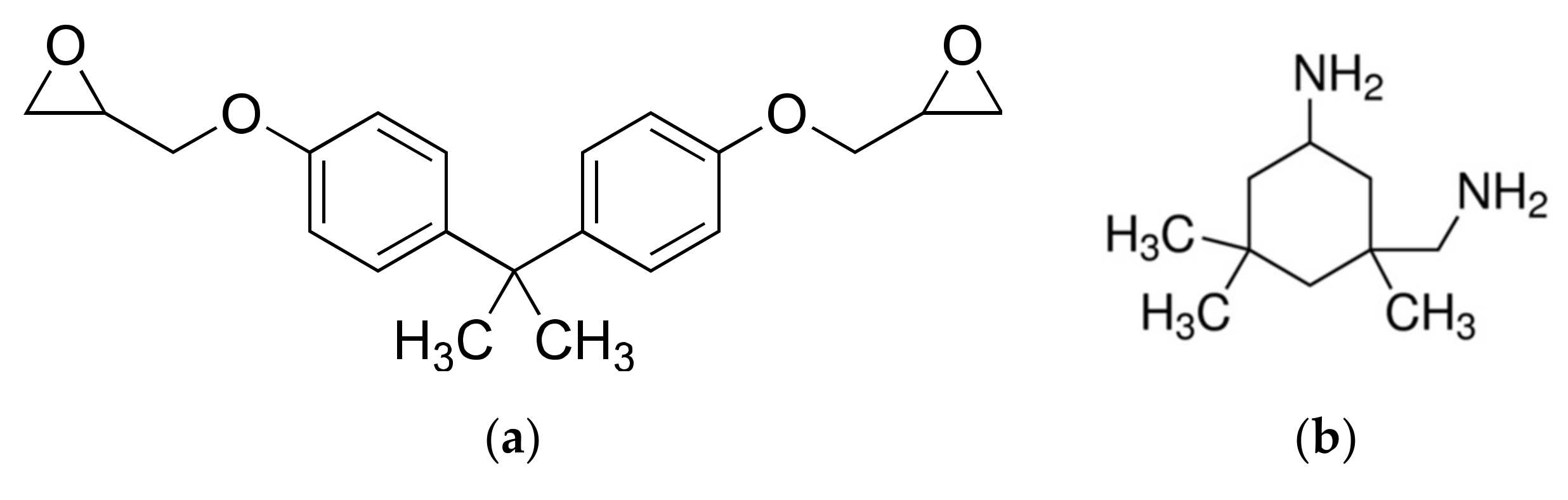
2.1. Materials
2.2. Fabrication
2.3. Characterization
3. Results & Discussion
3.1. Effect of CNT on Stress, Strain and Modulus of EP Composites
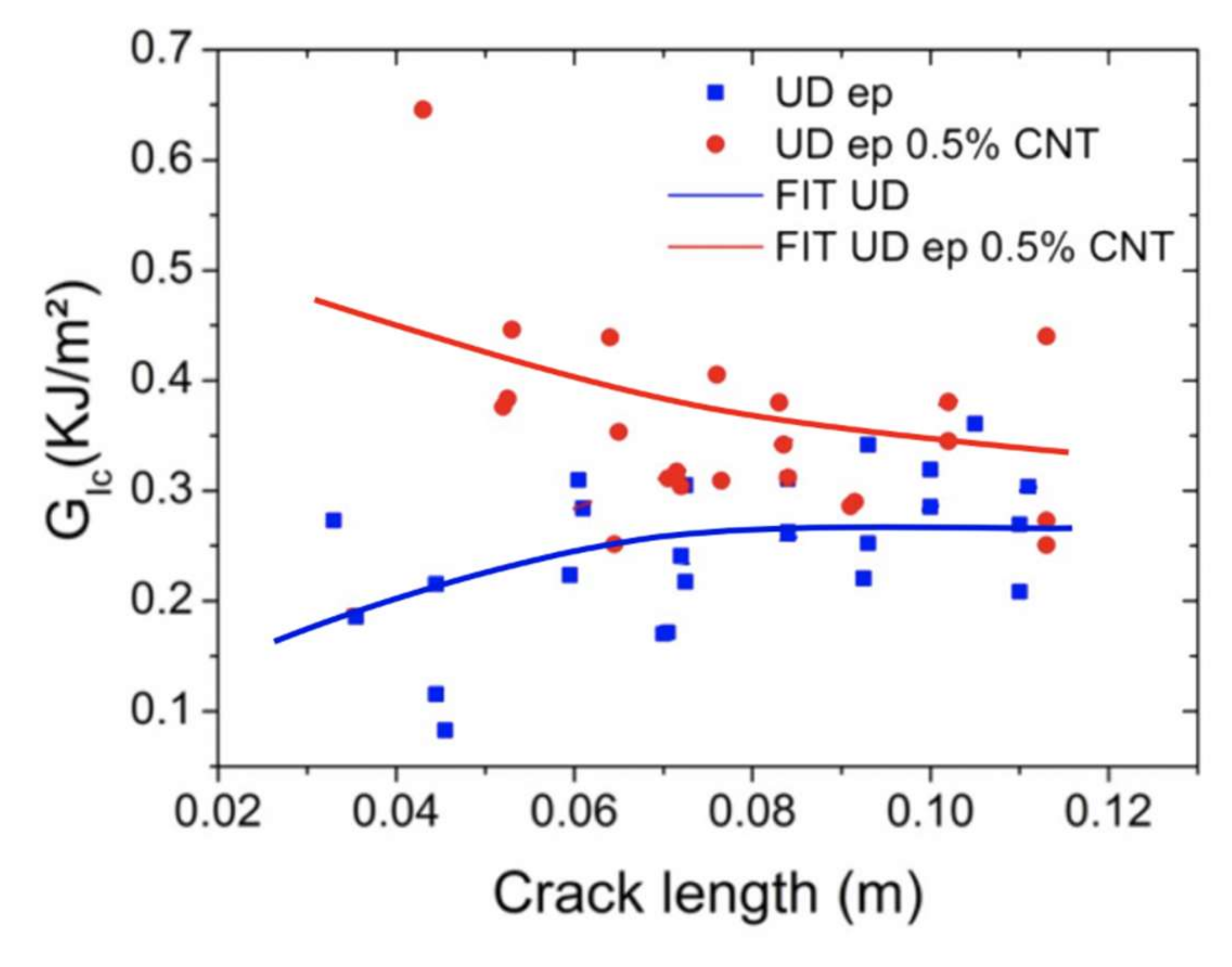
3.2. Mode I Inter-Laminar Fracture Toughness
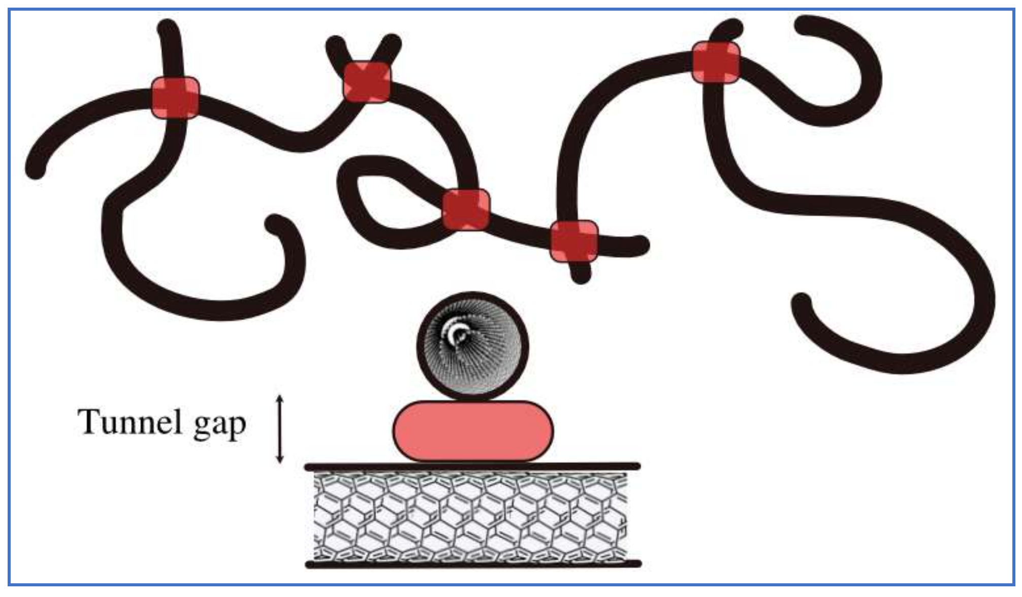
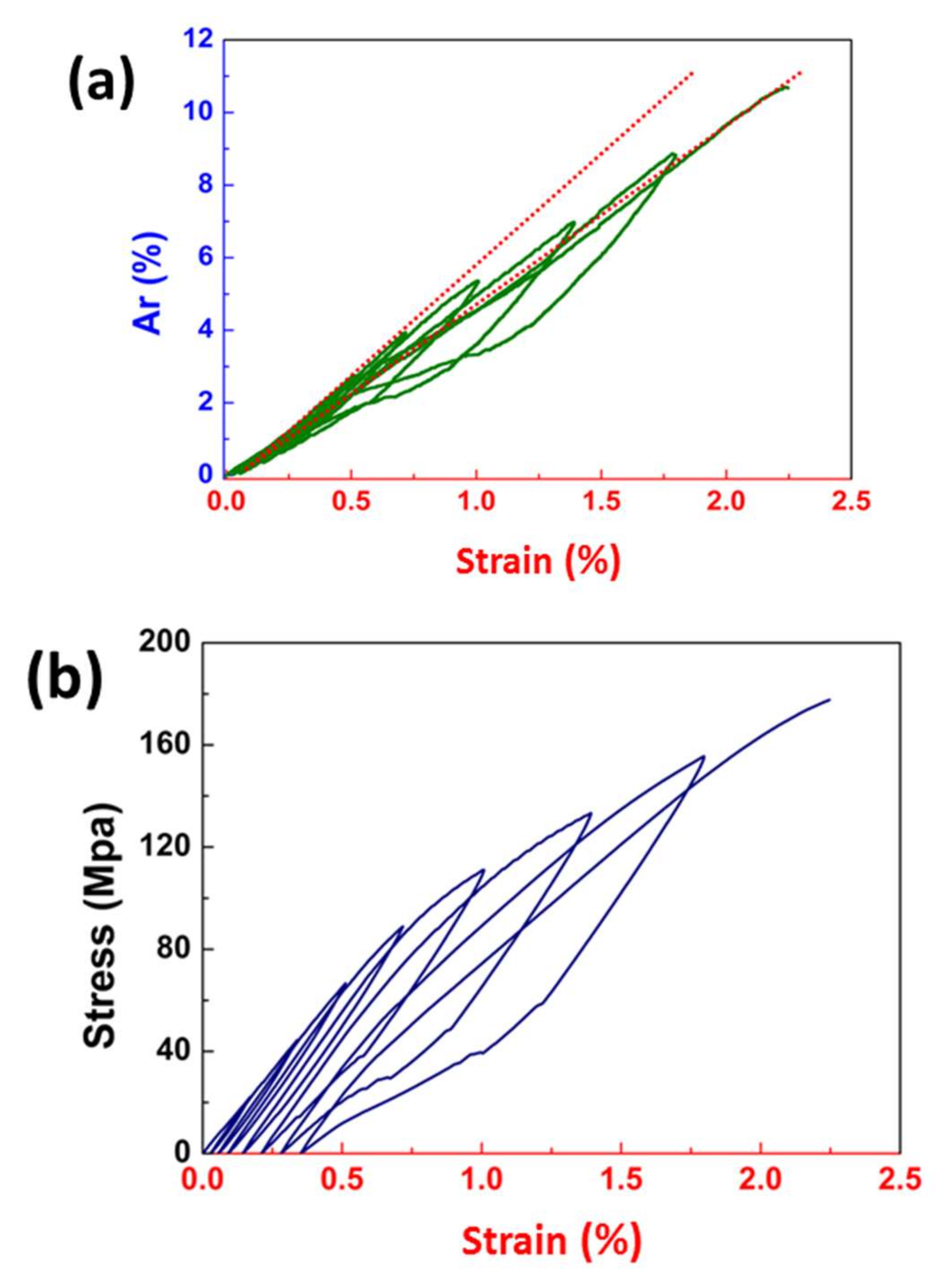
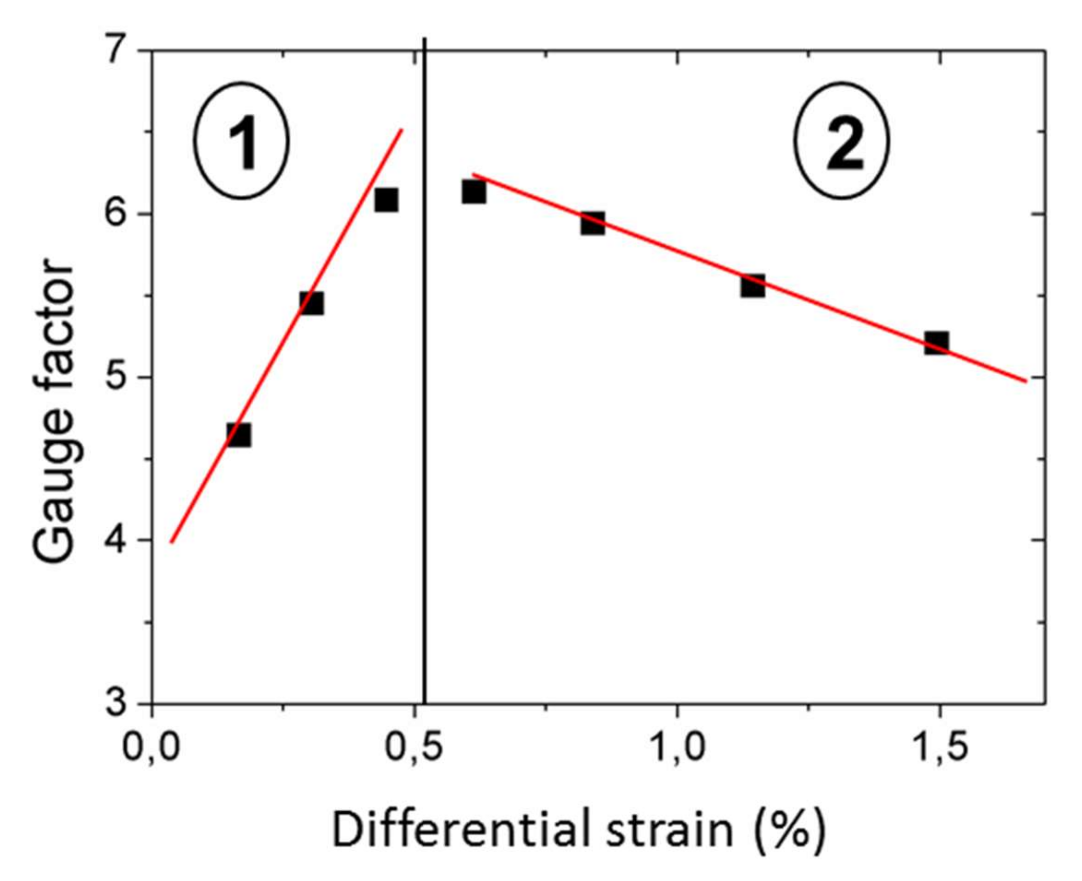
3.3. Strain Sensing with CNT Based Nanocomposites
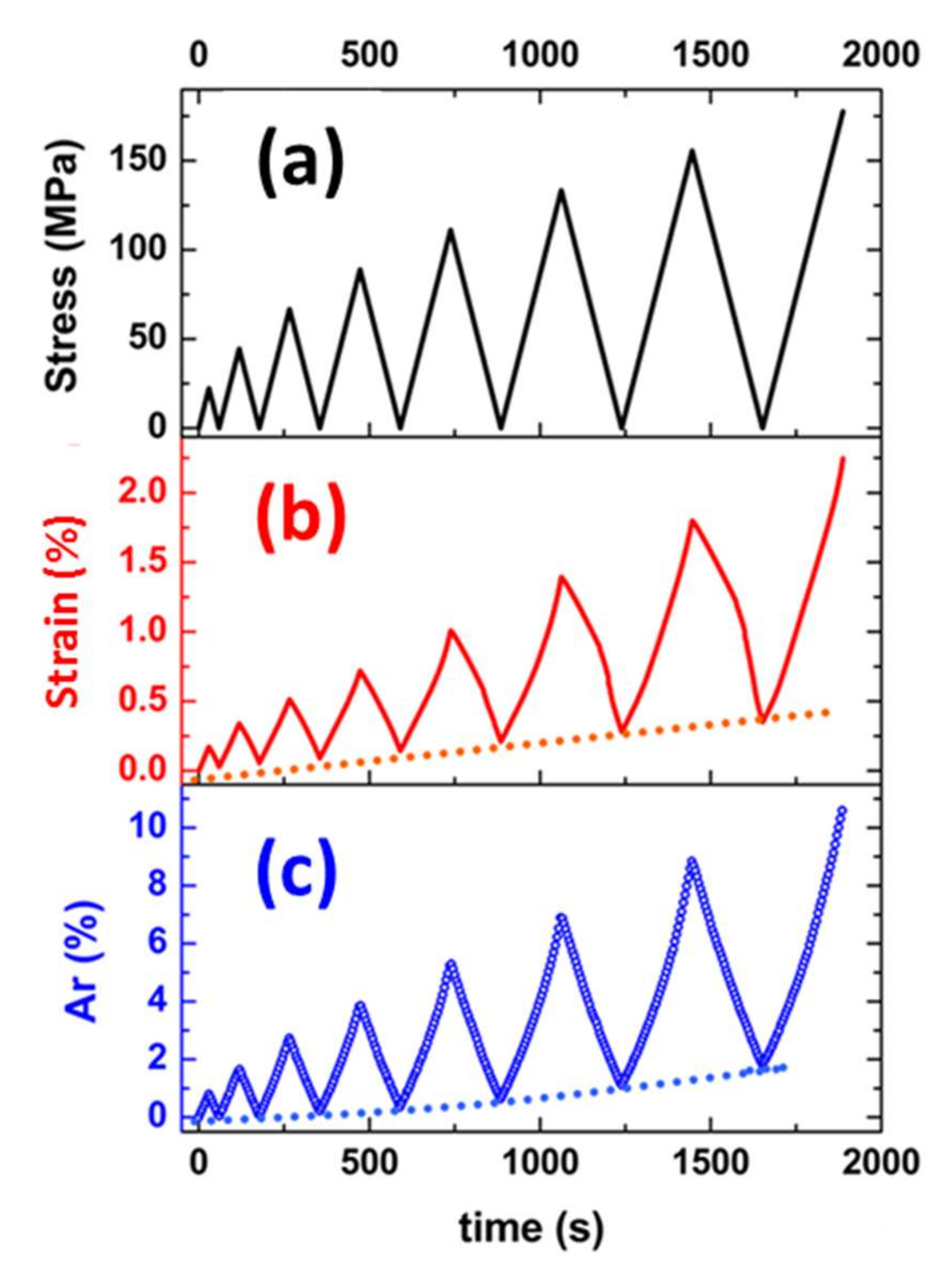
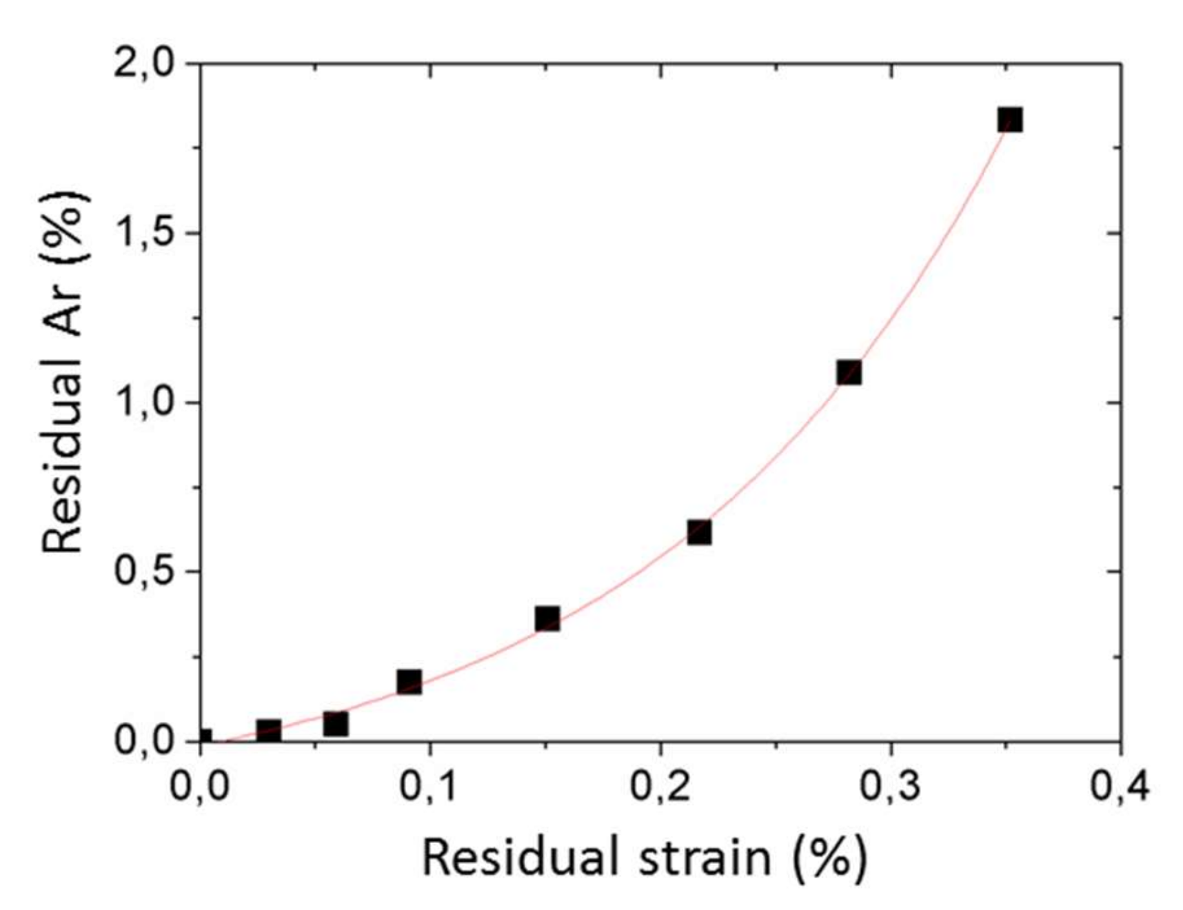
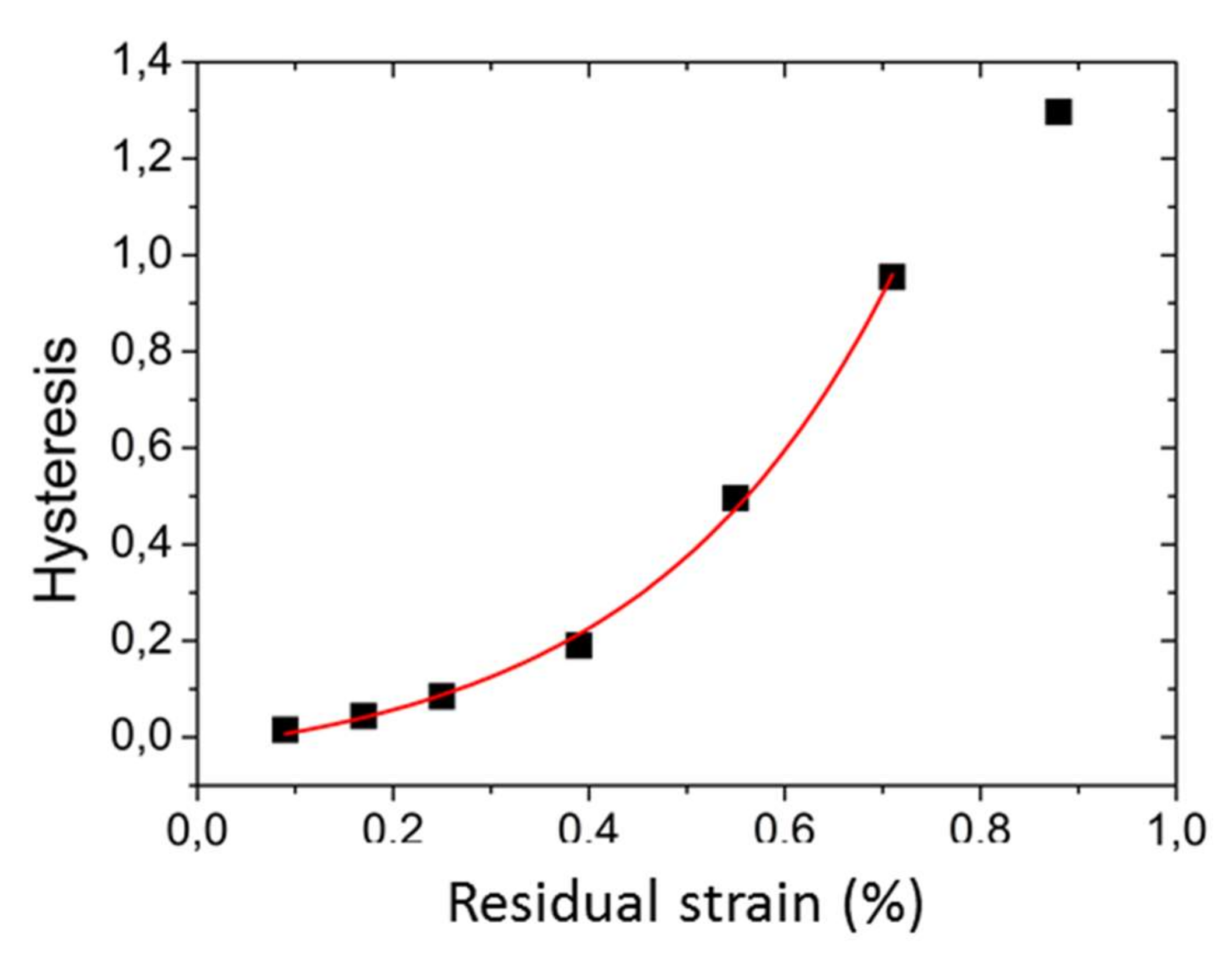
3.4. Damage Accumulation Monitoring
4. Conclusions
Supplementary Materials
Author Contributions
Funding
Acknowledgments
Conflicts of Interest
References
- Iijima, S. Helical microtubules of graphitic carbon, Nature 1991, 354, 56–58. Nature 1991, 354, 56–58. [Google Scholar] [CrossRef]
- Ajayan, P.M.; Stephan, O.; Colliex, C.; Trauth, D. Aligned carbon nanotube arrays formed by cutting a polymer resin-nanotube composite. Science 1994, 265, 1212–1214. [Google Scholar] [CrossRef] [PubMed]
- Calvert, P. A recipe for strength. Nature 1999, 399, 210–211. [Google Scholar] [CrossRef]
- Salvetat, J.P.; Bonard, J.M.; Thomson, N.H.; Kulik, A.J.; Forro, L.; Benoit, W.; Zuppiroli, L. Mechanical properties of carbon nanotubes. Appl. Phys. A 1999, 69, 255–260. [Google Scholar] [CrossRef]
- Thostenson, E.T.; Ren, Z.; Chou, T.W. Advances in the science and technology of carbon nanotubes and their composites: A review. Compos. Sci. Technol. 2001, 61, 1899–1912. [Google Scholar] [CrossRef]
- Coleman, J.N.; Khan, U.; Blau, W.J.; Gun’ko, Y.K. Small but strong: A review of the mechanical properties of carbon nanotube–polymer composites. Carbon 2006, 44, 1624–1652. [Google Scholar] [CrossRef]
- Yang, B.X.; Pramoda, K.P.; Xu, G.Q.; Goh, S.H. Mechanical reinforcement of polyethylene using polyethylene-grafted multiwalled carbon nanotubes. Adv. Funct. Mater. 2007, 17, 2062–2069. [Google Scholar] [CrossRef]
- Gawryla, M.D.; Liu, L.; Grunlan, J.C.; Schiraldi, D.A. PH tailoring electrical and mechanical behavior of polymer–clay–nanotube aerogels. Macromol. Rapid Commun. 2009, 30, 1669–1673. [Google Scholar] [CrossRef]
- Park, K.Y.; Lee, S.E.; Kim, C.G.; Han, J.H. Application of CNT-added glass fabric/epoxy composites to electromagnetic wave shielding enclosures. Compos. Struct. 2007, 81, 401–407. [Google Scholar] [CrossRef]
- Qu, L.; Dai, L. Gecko-foot-mimetic aligned single-walled carbon nanotube dry adhesives with unique electrical and thermal properties. Adv. Mater. 2007, 19, 3844–3849. [Google Scholar] [CrossRef]
- Villmow, T.; John, A.; Pötschke, P.; Heinrich, G. Polymer/carbon nanotube composites for liquid sensing: Selectivity against different solvents. Polymer 2012, 53, 2908–2918. [Google Scholar] [CrossRef]
- Zhang, R.; Dowden, A.; Deng, H.; Baxendale, M.; Peijs, T. Conductive network formation in the melt of carbon nanotube/thermoplastic polyurethane composite. Compos. Sci. Technol. 2009, 69, 1499–1504. [Google Scholar] [CrossRef]
- Laquintinie, P.S.; Sachan, A.; Feller, J.F.; Lahuec, C.; Castro, M.; Seguin, F.; Dupont, L. An electronic nose prototype for the on-field detection of nerve agents. IEEE Sens. 2018, 1–4. [Google Scholar] [CrossRef]
- Kim, Y.; Chortos, A.; Xu, W.; Liu, Y.; Oh, J.Y.; Son, D.; Kang, J.; Foudeh, A.M.; Zhu, C.; Lee, Y.; et al. A bioinspired flexible organic artificial afferent nerve. Science 2018, 360, 998–1003. [Google Scholar] [CrossRef] [PubMed]
- Zhou, X.; Zhu, L.; Fan, L.; Deng, H.; Fu, Q. Fabrication of highly stretchable, washable, wearable, water-repellent strain sensors with multi-stimuli sensing ability. Acs Appl. Mater. Interfaces 2018, 10, 31655–31663. [Google Scholar] [CrossRef] [PubMed]
- Terrones, M. Science and technology of the twenty first century: Synthesis, properties, and applications of carbon nanotubes. Ann. Rev. Mater. Res. 2003, 33, 419–501. [Google Scholar] [CrossRef]
- Kim, D.H.; Lu, N.; Ma, R.; Kim, Y.S.; Kim, R.H.; Wang, S.; Wu, J.; Won, S.M.; Tao, H.; Islam, A.; et al. Epidermal Electronics. Science 2011, 333, 838–843. [Google Scholar] [CrossRef]
- Schroeder, V.; Evans, E.D.; Wu YC, M.; Voll CC, A.; McDonald, B.R.; Savagatrup, S.; Swager, T.M. Chemiresistive sensor array and machine learning classification of food. ACS Sens. 2019, 4, 2101–2108. [Google Scholar] [CrossRef]
- Fang, Y.; Zhao, J.; Zha, J.W.; Wang, D.R.; Dang, Z.M. Improved stability of volume resistivity in carbon black/ethylene-vinyl acetate copolymer composites by employing multi-walled carbon nanotubes as second filler. Polymer 2012, 53, 4871–4878. [Google Scholar] [CrossRef]
- Kim, D.; Kim, Y.; Choi, K.; Grunlan, J.C.; Yu, C. Improved thermoelectric behavior of nanotube-filled polymer composites with poly(3,4-ethylene dioxythiophene) poly(styrene sulfonate). ACS Nano 2010, 4, 513–523. [Google Scholar] [CrossRef]
- Antar, Z.; Feller, J.F.; Noël, H.; Glouannec, P.; Elleuch, K. Thermoelectric behaviour of melt processed carbon nanotube/graphite/poly(lactic acid) conductive biopolymer nanocomposites (CPC). Mater. Lett. 2012, 67, 210–214. [Google Scholar] [CrossRef]
- Dai, L. Intelligent Macromolecules for Smart Devices: From Materials Synthesis to Device Applications 2004; Springer: London, UK, 2004; pp. 1–496. [Google Scholar]
- Varadan, V.K.; Vinoy, K.J.; Gopalakrishnan, S. Smart Material Systems & MEMS: Design & Development Methodologies; John Wiley & Sons: Chichester, UK, 2006; pp. 1–404. [Google Scholar]
- Kang, I.; Heung, Y.Y.; Kim, J.H.; Lee, J.W.; Gollapudi, R.; Subramaniam, S.; Narasimhadevara, S.; Hurd, D.; Kirikera, G.R.; Shanov, V.; et al. Introduction to carbon nanotube and nanofibre smart materials. Compos. B Eng. 2006, 37, 382–394. [Google Scholar] [CrossRef]
- Feller, J.F.; Castro, M.; Kumar, B. Polymer carbon nanotube conductive nanocomposites for sensing. In Polymer Carbon Nanotube Composites: Preparation, Properties and Applications; McNally, T., Pötschke, P., Eds.; Woodhead Publishing: Cambridge, UK, 2011; pp. 760–803. [Google Scholar]
- Feller, J.F. 6.10 Electrically Conductive Nanocomposites. In Comprehensive. Composite Materials II, 2nd ed.; Beaumont, P.W.R., Zweben, C.H., Eds.; Elsevier: Amsterdam, The Netherlands, 2018; pp. 248–314. [Google Scholar]
- Yamada, T.; Hayamizu, Y.; Yamamoto, Y.; Yomogida, Y.; Izadi-Najafabadi, A.; Futuba, D.N.; Hata, K. A stretchable carbon nanotube strain sensor for human-motion detection. Nat. Nanotechnol. 2011, 6, 296–301. [Google Scholar] [CrossRef] [PubMed]
- Lipomi, D.J.; Vosgueritchian, M.; Tee BC, K.; Hellstrom, S.L.; Lee, J.; Fox, C.H.; Bao, Z. Skin-like pressure and strain sensors based on transparent elastic films of carbon nanotubes. Nat. Nanotechnol. 2011, 6, 788–792. [Google Scholar] [CrossRef] [PubMed]
- Robert, C.; Feller, J.F.; Castro, M. Sensing skin for strain monitoring made of PC-CNT conductive polymer nanocomposite sprayed layer by layer. ACS Appl. Mater. Interfaces 2012, 4, 3508–3516. [Google Scholar] [CrossRef]
- Zhang, R.; Deng, H.; Valenca, R.; Jin, J.; Fu, Q.; Bilotti, E.; Peijs, T. Strain sensing behaviour of elastomeric composite films containing carbon nanotubes under cyclic loading. Compos. Sci. Technol. 2013, 74, 1–5. [Google Scholar] [CrossRef]
- Zhao, H.; Bai, J. Highly sensitive piezo-resistive graphite nanoplatelet-carbon nanotube hybrids/polydimethylsilicone composites with improved conductive network construction. ACS Appl. Mater Interfaces 2015, 7, 9652–9659. [Google Scholar] [CrossRef]
- Lu, J.; Castro, M.; Feller, J.F. Thermo- and chemo-electrical behaviour of carbon nanotube filled co-continuous conductive polymer nanocomposites (CPC) to develop amperometric sensors. Mater. Res. Soc. Symp. Proc. 2009, 1143E. [Google Scholar] [CrossRef]
- Kumar, B.; Castro, M.; Feller, J.F. Poly(lactic acid)-multiwall nanotube conductive biopolymer nanocomposite vapour sensors. Sens. Actuators B Chem. 2012, 161, 621–628. [Google Scholar] [CrossRef]
- Kumar, B.; Feller, J.F.; Castro, M.; Lu, J. Conductive bio-polymer nano-composites (CPC): Chitosan-carbon nanotube transducers assembled via spray layer-by-layer for volatile organic compound sensing. Talanta 2010, 81, 908–915. [Google Scholar] [CrossRef]
- Lu, J.; Park, B.J.; Kumar, B.; Castro, M.; Choi, H.J.; Feller, J.F. Polyaniline nanoparticle-carbon nanotube hybrid network vapour sensors with switchable chemo-electrical polarity. Nanotechnology 2010, 21, 255501. [Google Scholar] [CrossRef] [PubMed]
- Spitalsky, Z.; Tasi, D.; Papgelis, K.; Galioti, C. Carbon nanotube-polymer composites: Chemistry, processing mechanical and electrical properties. Prog. Polym. Sci. 2010, 35, 357–401. [Google Scholar] [CrossRef]
- Gojny, F.H.; Wichmann MH, G.; Kopke, U.; Fiedler, B.; Schulte, K. Carbon nanotube-reinforced epoxy composites: Enhanced stiffness and fracture toughness at low nanotube content. Compos. Sci. Technol. 2004, 64, 2363–2371. [Google Scholar] [CrossRef]
- Thostenson, E.T.; Ziaee, S.; Chou, T.W. Processing and electrical properties of carbon nanotube/vinyl ester nanocomposites. Compos. Sci. Technol. 2009, 69, 801–804. [Google Scholar] [CrossRef]
- Gojny, F.H.; Wichmann MH, G.; Fielder, B.; Schulte, K. Influence of different carbon nanotubes on the mechanical properties of epoxy matrix composites—A comparative study. Compos. Sci. Technol. 2005, 65, 2300–2313. [Google Scholar] [CrossRef]
- Gojny, F.H.; Wichmann MH, G.; Fielder, B.; Schulte, K. Influence of nano-modification on the mechanical and electrical properties of conventional fibre-reinforced matrix. Compos. Part A 2005, 36, 1525–1535. [Google Scholar] [CrossRef]
- Zhao, Q.; Wagner, H.D. Two-dimensional strain mapping in model fibre-polymer composites using nanotube Raman sensing. Compos. A Appl. Sci. Manuf. 2003, 34, 1219–1225. [Google Scholar] [CrossRef]
- Pham, G.T.; Park, Y.B.; Liang, Z.; Zhang, C.; Wang, B. Processing and modelling of conductive thermoplastic/carbon nanotube films for strain sensing. Compos. B Eng. 2008, 39, 209–216. [Google Scholar] [CrossRef]
- De la Vega, A.; Kinloch, I.A.; Young, R.J.; Bauhofer, W.; Schulte, K. Simultaneous global and local strain sensing in SWCNT-Epoxy composites by Raman and impedance spectroscopy. Compos. Sci. Technol. 2011, 71, 160–166. [Google Scholar] [CrossRef]
- Thostenson, E.T.; Chou, T.W. Real-time in situ sensing of damage evolution in advanced fibre composites. Nanotechnology 2008, 19, 215713. [Google Scholar] [CrossRef]
- Li, C.; Chou, T.W. Modeling of damage sensing fibre composites using carbon nanotube networks. Compos. Sci. Technol. 2008, 68, 3373–3379. [Google Scholar] [CrossRef]
- Gao, L.; Thostenson, E.T.; Zhang, Z.; Chou, T.W. Sensing of damage mechanism in fibre-reinforced composite under cyclic loading using carbon nanotubes. Adv. Funct. Mater. 2009, 19, 123–130. [Google Scholar] [CrossRef]
- Abot, J.L.; Song, Y.; Vatsavaya, M.S.; Medikonda, S.; Kier, Z.; Jayasinghe, C.; Rooy, N.; Shanov, V.N.; Schulz, M.J. Delamination detection with carbon nanotube thread in self-sensing composite materials. Compos. Sci. Technol. 2010, 70, 1113–1119. [Google Scholar] [CrossRef]
- Nag-Chowdhury, S.; Bellegou, H.; Pillin, I.; Castro, M.; Longrais, P.; Feller, J.F. Interfacial nanocomposite sensors (sQRS) for the core monitoring of polymer composites’ fatigue and damage analysis. NanoComposites 2018, 4(3), 69–79. [Google Scholar] [CrossRef]
- Chou, T.W.; Gao, L.; Thostenson, E.T.; Zhang, Z.; Byun, J.H. An assessment of the science and technology of carbon nanotube-based fibres and composites. Compos. Sci. Technol. 2010, 70, 1–19. [Google Scholar] [CrossRef]
- Zhang, H.; Bilotti, E.; Peijs, T. The use of carbon nanotubes for damage sensing and structural health monitoring in laminated composites: A review. NanoComposites 2016, 4, 167–184. [Google Scholar] [CrossRef]
- Nag-Chowdhury, S.; Bellegou, H.; Pillin, I.; Castro, M.; Longrais, P.; Feller, J.F. Non-intrusive health monitoring of infused composites with embedded carbon quantum piezo-resistive sensors. Compos. Sci. Technol. 2016, 123, 286–294. [Google Scholar] [CrossRef]
- Kumar, S.; Falzon, B.G.; Hawkins, S.C. Ultrasensitive embedded sensor for composite joints based on a highly aligned carbon nanotube web. Carbon 2019, 149, 380–389. [Google Scholar] [CrossRef]
- Arinstein, A.; Burman, M.; Gendelman, O.; Zussman, E. Effect of supramolecular structure on polymer nanotube elasticity. Nat. Nanotechnol. 2007, 2, 59–62. [Google Scholar] [CrossRef]
- Sui, X.; Wagner, H.D. Tough nanocomposites: The role of carbon nanotube type. Nano Lett. 2009, 9, 1423–1426. [Google Scholar] [CrossRef]
- Cuenot, S.; Fretigny, C.; Demoustier-Campagne, S.; Nysten, B. Measurement of elastic modulus of nanotubes by resonant contact atomic force microscopy. J. Appl. Phys. 2003, 9, 5650–5655. [Google Scholar] [CrossRef]
- Salvetat, J.P.; Briggs GA, D.; Bonard, J.M.; Basca, R.R.; Kulik, A.J.; Stockli, T. Elastic and shear moduli of single walled nanotube ropes. Phys. Rev. Lett. 1999, 82, 944–947. [Google Scholar] [CrossRef]
- Ajayan, P.M.; Schadler, L.S.; Giannaris, C.; Rubio, A. Single-walled nanotube-polymer composites: Strength and weaknesses. Adv. Mater. 2000, 12, 750–753. [Google Scholar] [CrossRef]
- Bai, J.B.; Allaoui, A. Effect of the length and the aggregate size of MWNTs on the improvement efficiency of the mechanical and electrical properties of nanocomposites-experimental investigation. Composites A 2003, 34, 689–694. [Google Scholar] [CrossRef]
- Sager, R.J.; Klein, P.J.; Lagoudas, D.C.; Zhang, Q.; Liu, J.; Dai, L.; Baur, J.W. Effect of carbon nanotubes on the interfacial shear strength of T650 carbon fibre in an epoxy matrix. Compos. Sci. Technol. 2009, 69, 898–904. [Google Scholar] [CrossRef]
- Keeple, K.L.; Sanborn, G.P.; Lacasse, P.A.; Gruenberg, K.M.; Ready, W.J. Improved fracture toughness of carbon fibre composite functionalized with multi walled carbon nanotubes. Carbon 2008, 46, 2023–2033. [Google Scholar]
- Liu, L.; Wagner, H.D. Rubbery and glassy epoxy resins reinforced with carbon nanotubes. Compos. Sci. Technol. 2005, 65, 1861–1868. [Google Scholar] [CrossRef]
- Wagner, H.D.; Lourie, O.; Feldman, Y.; Tenne, R. Stress induced fragmentation of multiwall carbon nanotubes in a polymer matrix. Appl. Phys. Lett. 1998, 72, 188–190. [Google Scholar] [CrossRef]
- Wang, X.; Chung, D.D.L. Real-time monitoring of fatigue damage and dynamic strain in carbon fibre-matrix composite by electrical resistance measurement. Smart Mater. Struct. 1997, 6, 504–508. [Google Scholar] [CrossRef]
- Tripathi, K.M.; Vincent, F.; Castro, M.; Feller, J.F. Flax fibres–epoxy with embedded nanocomposite sensors to design lightweight smart bio-composites. Nanocomposites 2016, 2, 125–134. [Google Scholar] [CrossRef]
- Zhang, X.W.; Pan, Y.; Zheng, Q.; Yi, W.S. Time dependence of piezoresistance for the conductor-filled polymer composites. J. Polym. Sci. B 2000, 38, 2739–2749. [Google Scholar] [CrossRef]
- Knite, M.; Tupureina, V.; Fuith, A.; Zavickis, J.; Teteris, V. Polyisoprene-multi-wall carbon nanotube composites for strain sensing. Mater. Sci. Eng. C 2007, 27, 1125–1128. [Google Scholar] [CrossRef]
- Takeda, T.; Shindo, Y.; Kuronuma, Y.; Narita, F. Modeling and characterization of the electrical conductivity of carbon nanotube-based polymer composites. Polymer 2011, 52, 3852–3856. [Google Scholar] [CrossRef]
- Thostenson, E.T.; Chou, T.W. Processing-structure-multi-functional property relationship in carbon nanotube/epoxy composites. Carbon 2006, 44, 3022–3029. [Google Scholar] [CrossRef]
- EPOLAM 2020 Datasheet. Available online: https://advanced-resins.sika.com/en/solutions_products/product-groups/composite-resin-systems/composite-resin-systems-for-hand-lay-up/epolam-2020.html (accessed on 29 November 2017).
- Seyhan, A.T.; Tanoglu, M.; Schulte, K. Mode I and mode II fracture toughness of E-glass non crimp fabric carbon nanotube (CNT) modified polymer based composites. Eng. Fract. Mech. 2008, 75, 5151–5162. [Google Scholar] [CrossRef]
- Penudamu, D.; Dutta, A.; Pharr, G.M.; Files, B. Mechanical properties of blended SWCNT composites. J. Mater. Res. 2003, 18, 1849–1853. [Google Scholar]
- Breton, D.; Désarmot, G.; Salvetat, J.P.; Sinturel, C.; Béguin, F.; Bonnamy, S. Mechanical properties of multiwall carbon nanotubes/epoxy composites: Influence of network morphology. Carbon 2004, 42, 1027–1030. [Google Scholar] [CrossRef]
- Nadler, M.; Werner, J.; Mahrolz, T.; Riedel, U.; Hufenbach, W. Effect of CNT surface functionalization on the mechanical properties of multi walled carbon nanotube/epoxy-composites. Composites A 2009, 40, 932–937. [Google Scholar] [CrossRef]
- Guo, P.; Chen, X.; Gao, X.; Song, H.; Shen, H. Fabrication and mechanical properties of well-dispersed carbon nanotubes/epoxy composites. Compos. Sci. Technol. 2007, 40, 3331–3337. [Google Scholar] [CrossRef]
- Xiao, K.Q.; Zhang, L.C. The stress transfer efficiency of a single-walled carbon nanotube in epoxy matrix. J. Mater. Sci. 2004, 39, 4481–4486. [Google Scholar] [CrossRef]
- Fiedler, B.; Gojny, F.H.; Wichmann MH, G.; Nolte MC, M.; Schulte, K. Fundamental aspects of nano-reinforced composites. Compos. Sci. Technol. 2005, 66, 3115–3125. [Google Scholar] [CrossRef]
- Godara, A.; Mezzo, L.; Luizi, F.; Warrier, A.; Lomov, S.V.; Van Vuure, A.W.; Gorbatikh, L.; Moldenaers, P. Verpoest I, Influence of carbon nanotube reinforcement on the processing and the mechanical behaviour of carbon fibre/epoxy composites. Carbon 2009, 47, 2914–2923. [Google Scholar] [CrossRef]
- Jar, P.Y.; Davies, P. Matrix effect on the static and dynamic interlaminar fracture toughness of glass-fibre marine composites. Composites B 1998, 29, 505–516. [Google Scholar]
- Albertsen, H.; Ivens, J.; Peters, P.; Wevers, M.; Verpoest, I. Interlaminar fracture toughness of CFRP influenced by fibre surface treatment: Part 1 experimental results. Compos. Sci. Technol. 1995, 54, 133–145. [Google Scholar] [CrossRef]
- Jang, J.; Shin, S. Toughness improvement of tetrafunctional epoxy resin by using hydrolysed poly(ether imide). Polymer 1995, 36, 1199–1207. [Google Scholar] [CrossRef]
- Verrey, J.; Winkler, Y.; Michaud, V.; Manson, J.A.E. Interlaminar fracture toughness improvement in composites with hyperbranched polymer modified resin. Compos. Sci. Technol. 2005, 65, 1527–1536. [Google Scholar] [CrossRef]
- Gao, L.; Chou, T.W.; Thostenson, E.T.; Zuoguang, Z. A comparative study of damage sensing in fibre composites using uniformly and non-uniformly dispersed carbon nanotubes. Carbon 2010, 48, 3788–3794. [Google Scholar] [CrossRef]
- Böger, L.; Wichmann MH, G.; Meyer, L.O.; Schulte, K. Load and health monitoring in glass fibre reinforced composites with an electrically conductive nanocomposite epoxy matrix. Compos. Sci. Technol. 2008, 68, 1886–1894. [Google Scholar] [CrossRef]
- Seo, D.C.; Lee, J.J. Effect of embedded optical fibre sensors on transverse crack spacing of smart composite structures. Compos. Struct. 1995, 32, 51–58. [Google Scholar] [CrossRef]
- Lachman, N.; Bartholome, C.; Miaudet, P.; Maugey, M.; Poulin, P.; Wagner, H.D. Raman response of carbon nanotube/PVA fibres under strain. J. Phys. Chem. C 2009, 113, 4751–4754. [Google Scholar] [CrossRef]
- Suzuki, Y.; Ohnishi, M.; Suzuki, K.; Miura, H. Remote non-contact strain sensor using carbon nanotube-dispersed resin. In Proceedings of the Microsystems Packaging Assembly & Circuits Technology Conference, 2010, 5th International IMPACT, Taipei, Taiwan, 20–22 October 2010. [Google Scholar]
- Park, M.; Kim, H.; Youngblood, J.P. Strain-dependent electrical resistance of multiwalled nanotube/polymer composite films. Nanotechnology 2008, 19, 055705. [Google Scholar] [CrossRef] [PubMed]
- Bautista-Quijano, J.R.; Avilésa, F.; Aguilara, J.O.; Tapia, A. Strain sensing capabilities of a piezoresistive MWCNT-polysulfone film. Sens. Actuators A Phys. 2010, 159, 135–140. [Google Scholar] [CrossRef]


| Type of Test | Measured Parameter | (EP-0.5% CNT)/EP | {CF62/(EP-0.5CNT)37.5}/{CF62/EP-38} |
|---|---|---|---|
| (Longitudinal Mode) | (Transverse Mode) | ||
| Tensile Test | Young’s modulus ratio (%) | −2 | −18 |
| Stress at break ratio (%) | +4 | +15 | |
| Strain at break ratio (%) | −3 | +30 | |
| 3 Points Bending Test | Young’s modulus ratio (%) | +1 | −5 |
| Stress at break ratio (%) | +12 | +14 | |
| Strain at break ratio (%) | +12 | +25 |
© 2019 by the authors. Licensee MDPI, Basel, Switzerland. This article is an open access article distributed under the terms and conditions of the Creative Commons Attribution (CC BY) license (http://creativecommons.org/licenses/by/4.0/).
Share and Cite
Robert, C.; Pillin, I.; Castro, M.; Feller, J.-F. Multifunctional Carbon Nanotubes Enhanced Structural Composites with Improved Toughness and Damage Monitoring. J. Compos. Sci. 2019, 3, 109. https://doi.org/10.3390/jcs3040109
Robert C, Pillin I, Castro M, Feller J-F. Multifunctional Carbon Nanotubes Enhanced Structural Composites with Improved Toughness and Damage Monitoring. Journal of Composites Science. 2019; 3(4):109. https://doi.org/10.3390/jcs3040109
Chicago/Turabian StyleRobert, Colin, Isabelle Pillin, Mickaël Castro, and Jean-Francois Feller. 2019. "Multifunctional Carbon Nanotubes Enhanced Structural Composites with Improved Toughness and Damage Monitoring" Journal of Composites Science 3, no. 4: 109. https://doi.org/10.3390/jcs3040109
APA StyleRobert, C., Pillin, I., Castro, M., & Feller, J.-F. (2019). Multifunctional Carbon Nanotubes Enhanced Structural Composites with Improved Toughness and Damage Monitoring. Journal of Composites Science, 3(4), 109. https://doi.org/10.3390/jcs3040109