Article

Does the Type of Polymer and Carbon Nanotube Structure Control the Electromagnetic Shielding in Melt-Mixed Polymer Nanocomposites?

1
Department of Chemistry, National Institute of Technology, Durgapur 713209, India
2
Department of Materials Engineering, Indian Institute of Science, Bangalore 560012, India
3
Leibniz-Institut für Polymerforschung Dresden e.V., Hohe Str. 6, 01069 Dresden, Germany
*
Authors to whom correspondence should be addressed.
J. Compos. Sci. 2020, 4(1), 9; https://doi.org/10.3390/jcs4010009
Submission received: 15 November 2019 / Revised: 3 January 2020 / Accepted: 9 January 2020 / Published: 15 January 2020
(This article belongs to the Special Issue Recent Advances in Carbon Nanotube Composites)

Abstract

:
A suitable polymer matrix and well dispersed conducting fillers forming an electrically conducting network are the prime requisites for modern age electromagnetic shield designing. An effective polymer-based shield material is designed that can attenuate 99.9% of incident electromagnetic (EM) radiation at a minimum thickness of <0.5 mm. This is accomplished by the choice of a suitable partially crystalline polymer matrix while comparing non-polar polypropylene (PP) with polar polyvinylidene fluoride (PVDF) and a best suited filler nanomaterial by comparing different types of carbon nanotubes such as; branched, single-walled and multi-walled carbon nanotubes, which were added in only 2 wt %. Different types of interactions (polar-polar and CH-π and donor-acceptor) make b-MWCNT more dispersible in the PVDF matrix, which together with high crystallinity resulted in the best electrical conductivity and electromagnetic shielding ability of this composite. This investigation additionally conceals the issues related to the thickness of the shield material just by stacking individual thin nanocomposite layers containing different carbon nanotube (CNT) types with 0.3 mm thickness in a simple manner and finally achieves 99.999% shielding efficiency at just 0.9 mm thickness when using a suitable order of the different PVDF based nanocomposites.

1. Introduction

Recently, with the gigantic increment in the use of electronic gadgets and the quick advance of telecommunication innovation, electromagnetic radiation is being produced as an offshoot, which is turning into a genuine worldwide issue [1]. For more than 10 years, monitoring exposure of electromagnetic waves specifically has fuelled numerous level-headed discussions, which have regularly been quite heated. An examination of reports and scientific productions committed to this theme demonstrate that this radiation can meddle effectively in different surroundings instruments and causes a glitch [2,3]. Various examinations have been completed on the potentially hazardous impacts of electromagnetic waves on our wellbeing also [4].
Polymer composites with conductive fillers incorporated in them have high potential in different applications including electromagnetic interference (EMI) shielding [5,6]. These conducting fillers are usually randomly distributed in a polymer matrix and in general they require high loadings to attain an insulator/conductor transition. High loading of these fillers usually results in high melt viscosities, inferior mechanical properties, and low economic affordability [7]. Since the discovery of carbon nanotubes (CNTs), alluring properties simply change the mind of the researchers and CNTs have been utilized enormously in the polymer matrix as potential fillers [8,9,10]. The high aspect ratio, high electrical conductivity, and low percolation threshold in a suitable matrix are the most critical parameters for any polymer based shield designing [11,12]. Due to the presence of different structural confinements, CNTs can exist in different forms, such as singlewall and multiwall or non-functionalized and functionalized, which generally have diverse properties [13,14,15,16]. There is no study in literature dealing with comparable electromagnetic (EM) shielding properties when using different types of CNTs varying in their properties.
In regard of the previously mentioned certainties, herein, the first time in literature, we focus to determine the structural effect of different CNTs such as singlewalled carbon nanotubes (SWCNTs), multiwalled carbon nanotubes (MWCNTs), and branched MWCNTs (b-MWCNTs) in EM shield design while incorporated in the polymer matrix. In addition, we also compared our results by using two different semi-crystalline polymer matrices on the basis of their polarity and degree of crystallinity, namely non-polar polypropylene (PP) and polar polyvinylidene fluoride (PVDF). The state of dispersion of the three different types of CNTs in two different matrixes was investigated by morphological structures, rheology, differential scanning calorimetry (DSC), and electrical resistivity measurements. It has been found that due to the low van der Waals’ attraction forces and specific interaction between the PVDF and MWCNTs as well as branched MWCNTs such nanocomposites exhibited the highest values of total shielding effectiveness, especially in a multilayer assembly. This study is of paramount importance in guiding researchers working in this area.

2. Materials and Methods

2.1. Materials

Moplen HP400R, Polypropylene was procured from LyondellBasel. Kynar 720 poly (vinylidene fluoride) (PVDF) was purchased from Arkema. Tuball™ SWCNT with average diameter of 1.6 nm and a length exceeding 5 µm was purchased from OCSiAl S.a.r.l. (Luxembourg) [17]. NC7000™ MWCNT were obtained from Nanocyl, S.A. (Sambreville, Belgium) [18]. CNS-PEG branched MWCNT (b-MWCNT) were provided by Applied NanoStructured Solutions LLC (Baltimore, MD, USA).

2.2. Composite Preparation Method

A twin-screw microcompounder (Xplore DSM 15, Sittard, The Netherlands) (volume 15 ccm) was utilized for the preparation of polymer composites. PP-based composites were prepared at a temperature of 210 °C and a rotational speed of 250 rpm for 5 min. This melt mixing condition is comparable with that used in previous literature [17]. The PVDF-based composites were prepared as according to previous studies [19]. All polymer/CNT composites contain 2 wt % CNT.

2.3. Characterization

A DHR-3 rheometer (TA instrument, New Castle, DE, USA) was utilized here for measuring the flow characteristics of the composites under nitrogen atmosphere at 210 °C. Frequency sweeps were performed in the linear viscoelastic range between 0.1 and 100 rad/s at strain rate of 1% using compression molded plates (thickness 1 mm, diameter 25 mm).
A differential scanning calorimetry (Q2000 DSC TA instrument) was utilized for thermal characterization at a temperature range of −80 to 200 °C with a scan rate of ±10 K·min−1 under N2 atmosphere. The reported melting temperature is obtained from the second heating scan. The crystallinity α of the materials was calculated using ΔH values of 100% crystalline polymers as given in literature, whereby 207 J/g was used for 100% crystalline PP and 105 J/g for 100% crystalline PVDF [20,21].
For FT-IR, a Perkin-Elmer GX instrument was utilized for determining the polar crystalline phase of the PVDF and PP composites. Thin films of PP and PVDF were analyzed.
Raman spectra were recorded using a LabRam HR (UV) system using polymeric films.
A scanning electron microscope (Carl Zeiss GmbH, Jena, Germany) was utilized for Morphological characterization of the CNT powders and the cryo-fractured composites. All the composites were cryo-fractured in liquid N2 and the surfaces were coated with 3 nm platinum prior to the imaging.
A transmission electron microscope BX53M (Olympus, Olympus Deutschland GmbH, Germany) fitted with an Olympus DP71 camera was utilized to evaluate the dispersion of the fillers. Prior to the TEM imaging, extruded strands were cut into thin sections with a thickness of 5 µm using a Leica RM2265 microtome at room temperature and then fixed on glass slides using Aquatex.
A PW40EH (Otto-Paul-Weber GmbH, Remshalden, Germany) compression molding machine was utilized for preparing the samples for electrical characterization and EM shielding measurements. The samples were pressed into sheets having a diameter of 60 mm and different thickness of 0.3 mm, 0.5 mm, and 1 mm. PP composites were compression molded at 210 °C for 2 min [17] and PVDF composites at 200 °C for 2.5 min [19]. It is well established that unlike injection molding, compression molding does not impart any preferred orientation of nanoparticles.
Depending on the resistivity of the samples, here we have measured the electrical volume resistivity in two different configurations. For samples with high resistivity, the compression-molded plates were characterized using a Keithley 8009 Resistivity Test Fixture combined with a Keithley electrometer E6517A. Rectangular strips were cut so as to measure samples with low resistivity and were characterized by making use of a 2-point test fixture, combined with Keithley electrometer.
A vector network analyzer (VNA; Anritsu MS4642A) with a KEYCOM wave-guide adaptor was utilized for electromagnetic shielding measurements in 12–18 GHz frequency. Multi-layer assemblies were prepared by placing three individual layers of nanocomposites filled with the different CNTs (thickness 0.3 mm each) one upon another inside the adaptor of the waveguide. The scattering parameters were recorded and were used to estimate the total shielding effectiveness using the input and output power. The waveguide was thoroughly calibrated using short-open-load-transmission (SOLT).

3. Results

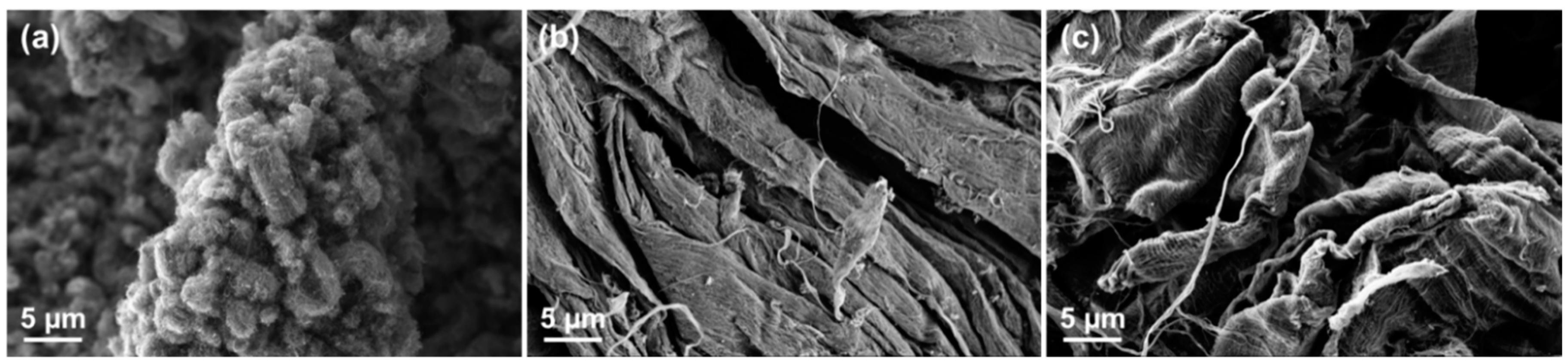
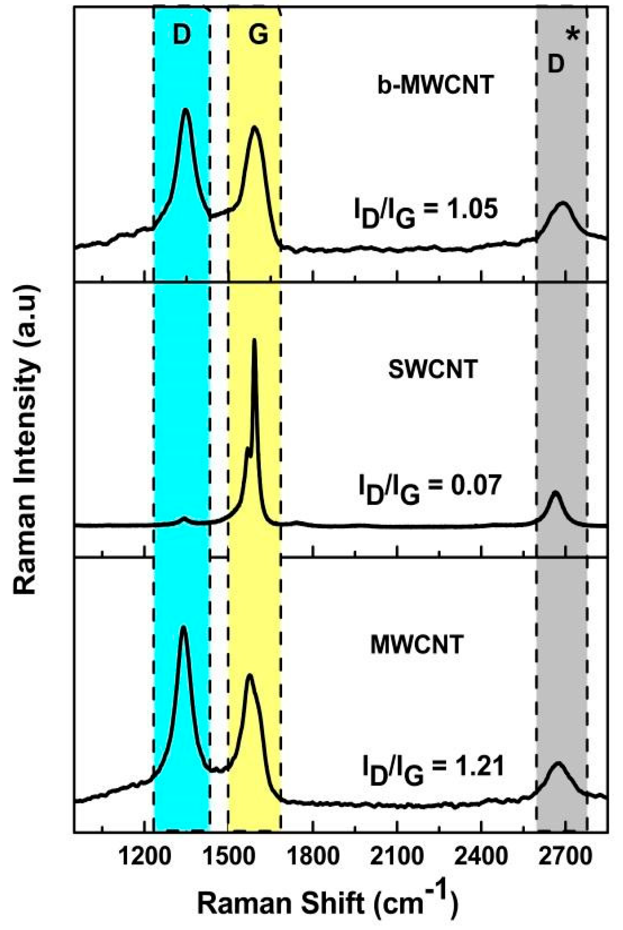
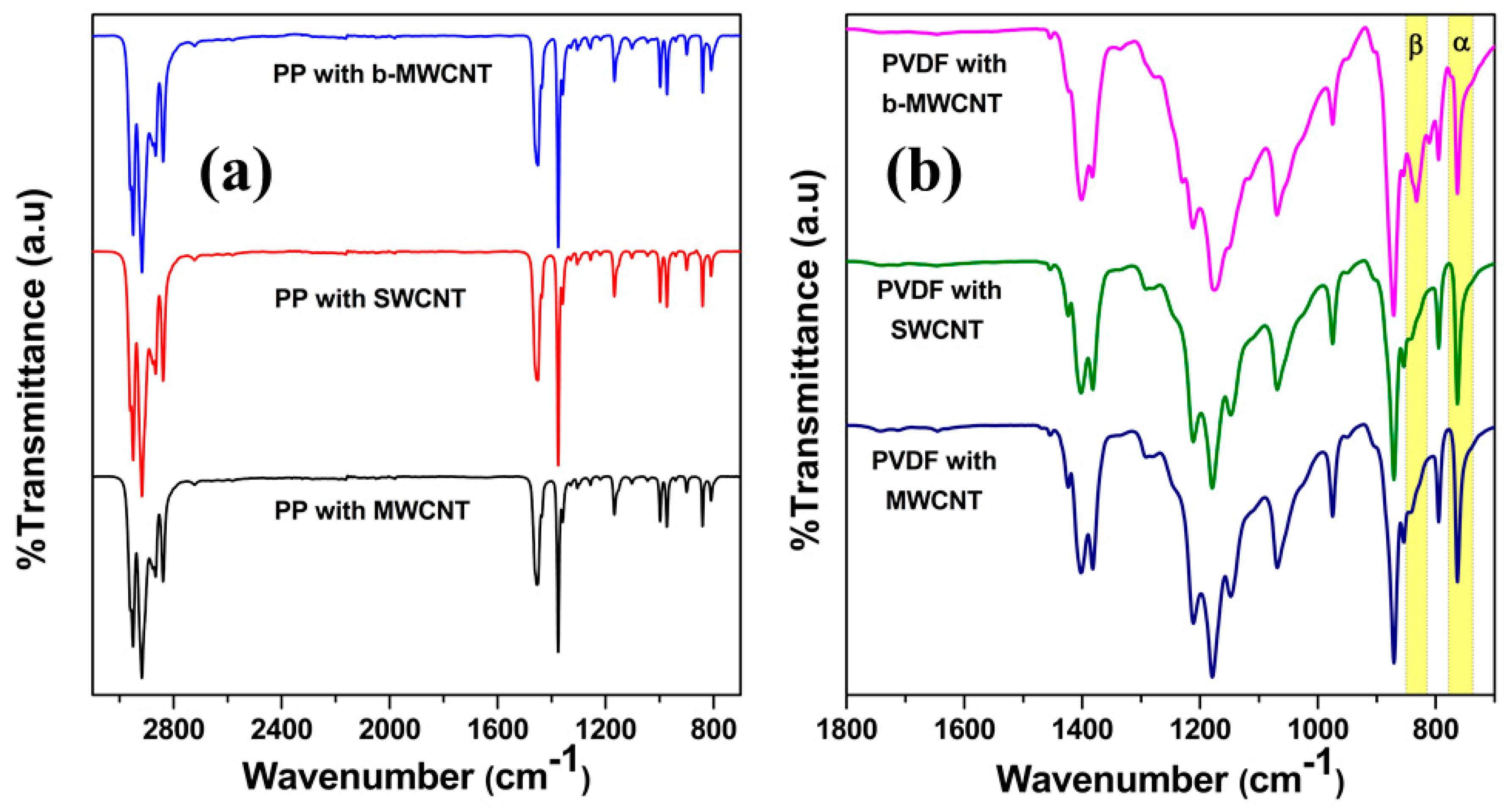
3.1. Characterization of Different Carbon Nanotubes

The CNT morphology was characterized using SEM (see Figure 1). A mat-like structure was observed for b-MWCNT as well as for SWCNT (Tuball) nanotubes. For MWCNT (NC7000) a finer combed yarn structure was well evident from the micrographs.
To determine the structural properties of the various CNTs, Raman spectroscopy was used. Figure 2 exhibits Raman spectra of MWCNT, SWCNT, and b-MWCNT, where each of them contains three different characteristics band. The D bands of MWCNT and b-MWCNT observed between 1240 and 1420 cm−1 feature an induced disorder arising from a double-resonance Raman scattering process which is, for the most part, starting from a non-zero focus phonon mode [22,23]. This band is as a result of the first order scattering process of sp2 carbons by the presence of layers, vacancies, or in-plane substitutional heteroatoms, which can break the basic symmetry of the graphitic network [24]. Here, due to the concentric graphene sheets rolled in a cylindrical fashion that creates a multi-layered architecture for originating the D bands of MWCNTs and b-MWCNT however, SWCNT does not have any such band. The intensity of the D band depends on the association of symmetry breaking parameters, which is directly proportional to the phonon density of states. It is interesting to note that for the second overtone of the D band no elastic defect related scattering is required, but it is related to the deformity of free sp2 carbons. Due to this reason, all of the carbon structures exhibited such D* band between 2600 and 2760 cm−1. The G band, which is originating from the in-plane tangential stretching of C–C bonds in graphite sheets, is observed here between 1500 and 1670 cm−1. The G band is the intrinsic feature of any CNT, which is firmly identified with the vibration in all sp2 carbon materials [24]. The vital part of the G-band is the asymmetric characteristic Raman line-shape, which depends on whether the nanotube is semiconducting or metallic, permitting promptly recognizing the two sorts. Here all three different CNTs show the G band spectra, which clarify their metallic characteristics, but the intensities and areas under the bands are different. For more understanding the intensity ratio of D and G band was evaluated (see Figure 2), which is a good indicator for extent of defects in CNTs. The ID/IG ratio is highest in MWCNTs, which means that there are defect sites than for both other CNT types. The charge conduction properties of these nanoparticles are also directly related to this ratio.

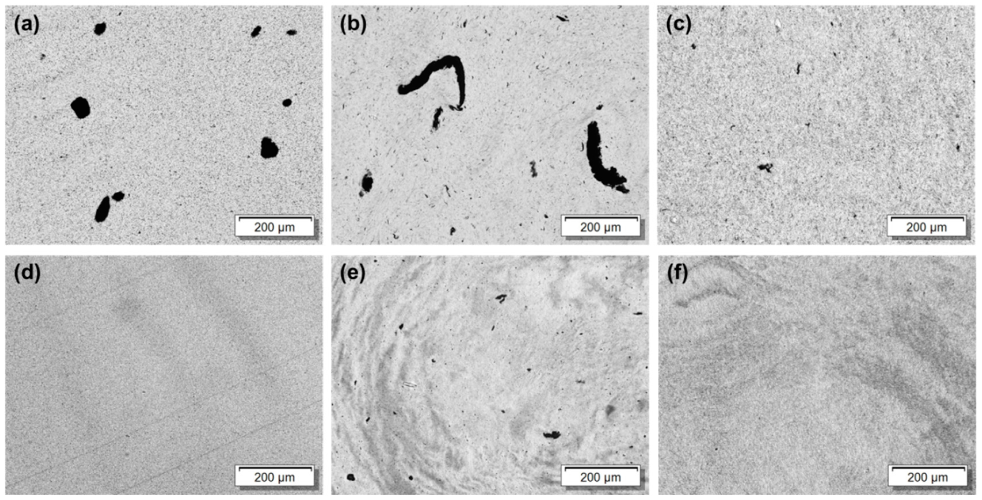
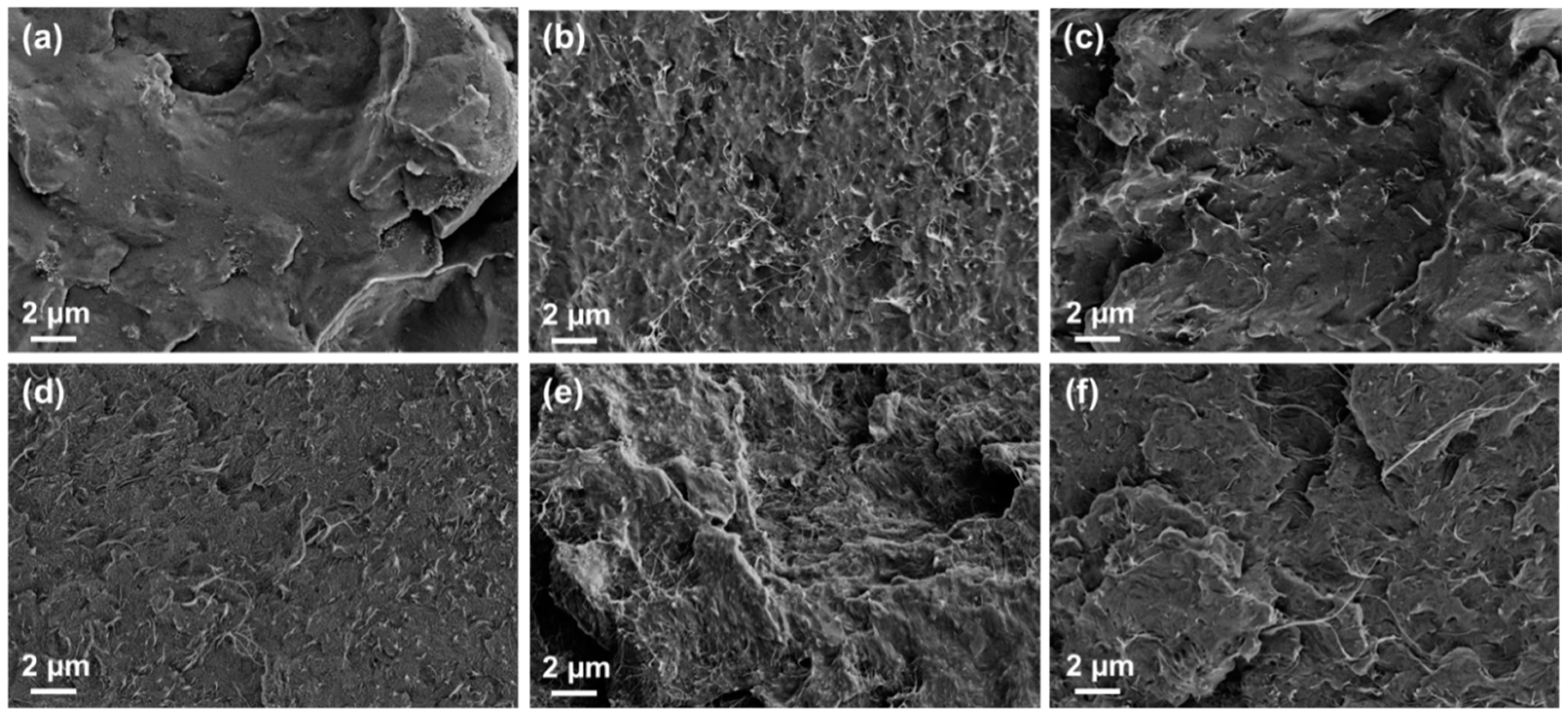
3.2. Dispersion of Various CNTs in the Matrices

Advancement of polymer nanocomposites has turned into an appealing subject lately because of their alluring properties. Numerous exploration endeavors have been coordinated towards constructing CNT/polymer composites for diverse applications [15]. Due to the entangled nature of CNTs and lack of sufficient interfacial interactions with the matrix, the structural properties in polymer/CNT composites is always lower than the predicted values [15]. The existing solutions for dispersing other conventional filler materials cannot be applied a priori for CNTs due to their nanometer scale and higher surface area [4]. The problem is more pronounced due to the cost minimization race in the commercial market of CNT sources, which actually provides more CNT types with highly entangled bundles. It is obvious that final nanocomposite properties may actually vary due to the different dispersibility of different CNTs in the used matrices.
Here we have attempted to disperse three different kinds of CNTs, which are MWCNTs (NC 7000), SWCNTs (Tuball), and b-MWCNTs (CNS-PEG) in PP and PVDF matrix systems. In both cases, the dispersion of the different CNTs is very different, as shown in Figure 3. The SWCNTs display a similar type of noticeable agglomerates irrespective of the matrix (Figure 3b,e). This can be attributed due to the formation of nano-ropes by stronger van der Waals’ forces of attraction, compared to the MWCNTs, which makes it difficult to separate them and infiltrate with the matrix polymer chains. The larger diameter due to the several concentric walls of MWCNTs favors their dispersion. However, the best dispersion is observed in composites filled with b-MWCNT, which may be attributed to the branched structure and the presence of PEG molecules on the nanotube surfaces, which eventually overcome the van der Waals’ forces of attraction between the tubes. The CNT dispersion in polar PVDF is quite better than in non-polar PP as inferred from the number and size of the agglomerates. The variation in CNT dispersibility controlled by the polarity of the polymer matrix was also discussed earlier in the literature [25,26,27]. At nano/micro scale, the CNTs were effectively dispersed, irrespective of their type, as indicated by SEM (see Figure 4) except for SWCNTs, where a dense CNT network is visible, however, the optical micrographs reveal that b-MWCNTs are better dispersed in the bulk.
It is envisaged that the difference in the degree of dispersion in any polymer matrix is largely dependent upon the physico-chemical property of the polymer. Both the polymers here are semi-crystalline in nature however; PVDF is more polar and can presumably interact better with the CNT network [28]. Further, CH-π interaction between the CNTs and PVDF also helps in the dispersion and favor the deagglomeration between CNTs [28,29]. Besides, it is also well established that during the melt compounding with PVDF, a possible interaction between the polymer and the CNTs at the molecular level is mainly due to the donor-acceptor complex between the delocalized π-electron clouds of CNTs and strongly electrophilic F groups, which facilitates the wrapping of PVDF chains on the surface of CNTs. thus, the polar crystalline structure and different type of electronic interactions lead to better dispersion of CNTs in PVDF than PP.

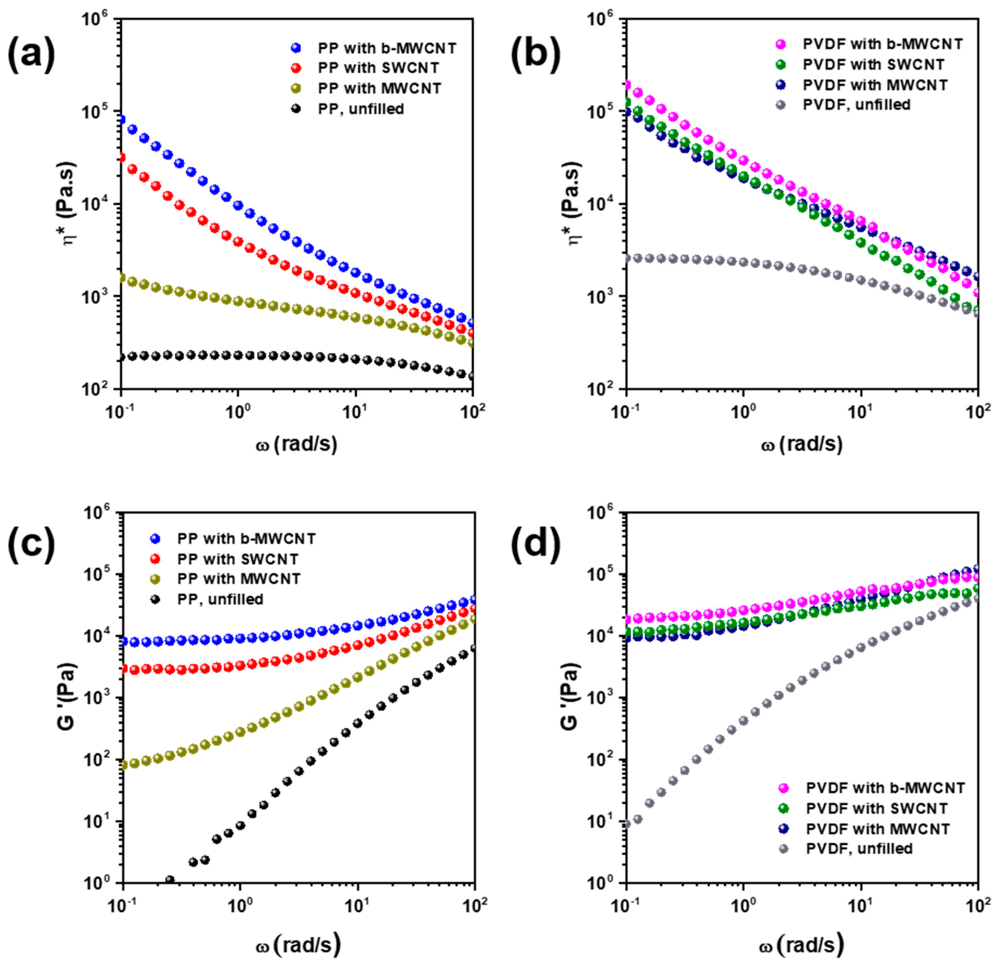
3.3. Effect of CNT Type on Melt-Viscosity

Rheological studies serve as a useful method in revealing the effects of incorporating nanoparticles in different polymer matrices as they reflect the filler network formation by a notable change in the complex viscosity and the viscoelastic properties [30]. The complex viscosity is a very important property and reflects summarily the polymer–particle interactions in different polymer matrices [31].
For both polymer matrices the complex viscosity as well as the storage modulus generally increases significantly with the addition of the CNTs, which is a well-known effect.
In the PP matrix, the melt viscosity of MWCNT based composites was lowest when compared with the other types of CNTs possibly due to worse dispersion throughout the matrix (see Figure 5a). For the PP/b-MWCNT composite exhibiting the best dispersion, the highest viscosity was measured. The overall distribution of CNTs as observed from light microscopy data (Figure 3a–c) correlates well with the melt-rheology data. Both distribution and dispersion play a vital role in restricting the motion of the polymer chain. Well dispersed but poorly distributed CNTs in the matrix are not effective for rendering high electrical conductivity in a given polymeric matrix. On the other hand, a very good distribution of well dispersed CNTs can form a network in the matrix volume and results in significant improvement in the electrical bulk conductivity. The latter scenario is also reflected in higher viscosity and storage modulus G’, which stems from the jammed network of polymer chains and CNTs.
In the PVDF matrix, the CNT dispersion was very similar for all three kinds of CNTs (Figure 3d–f), which is reflected in the similar complex viscosity as well as storage modulus curves (Figure 5b,d). There are very few differences measurable between the CNT types. Only the values for PVDF/b-MWCNT composite are slightly above those of the other composites.
Under this framework, the interaction between polymer and nanoparticles also influences the chain motion. When the host matrix interacts with the nanoparticles, the polymer chains surrounding the particle are immobilized, which leads to an effective particle volume fraction, which is greater than the actual particle volume fraction. This results in an improved storage modulus G′ at low frequencies. This observation echoes with the results of light microscopy wherein the well dispersed b-MWNTs were effectively well distributed in the host (irrespective of the matrix type) and thereby resulted in higher G’ values (Figure 5c,d).
The mentioned effects are much more pronounced in the PP matrix than in PVDF, where with all CNT types comparatively similar increases in the complex viscosity and storage modulus. At low frequencies, again the composites with b-MWCNTs show the highest | η * | and G′ values, whereas at the highest measured frequency of 100 rad/s MWCNT based composites show slightly higher values than the other composites.

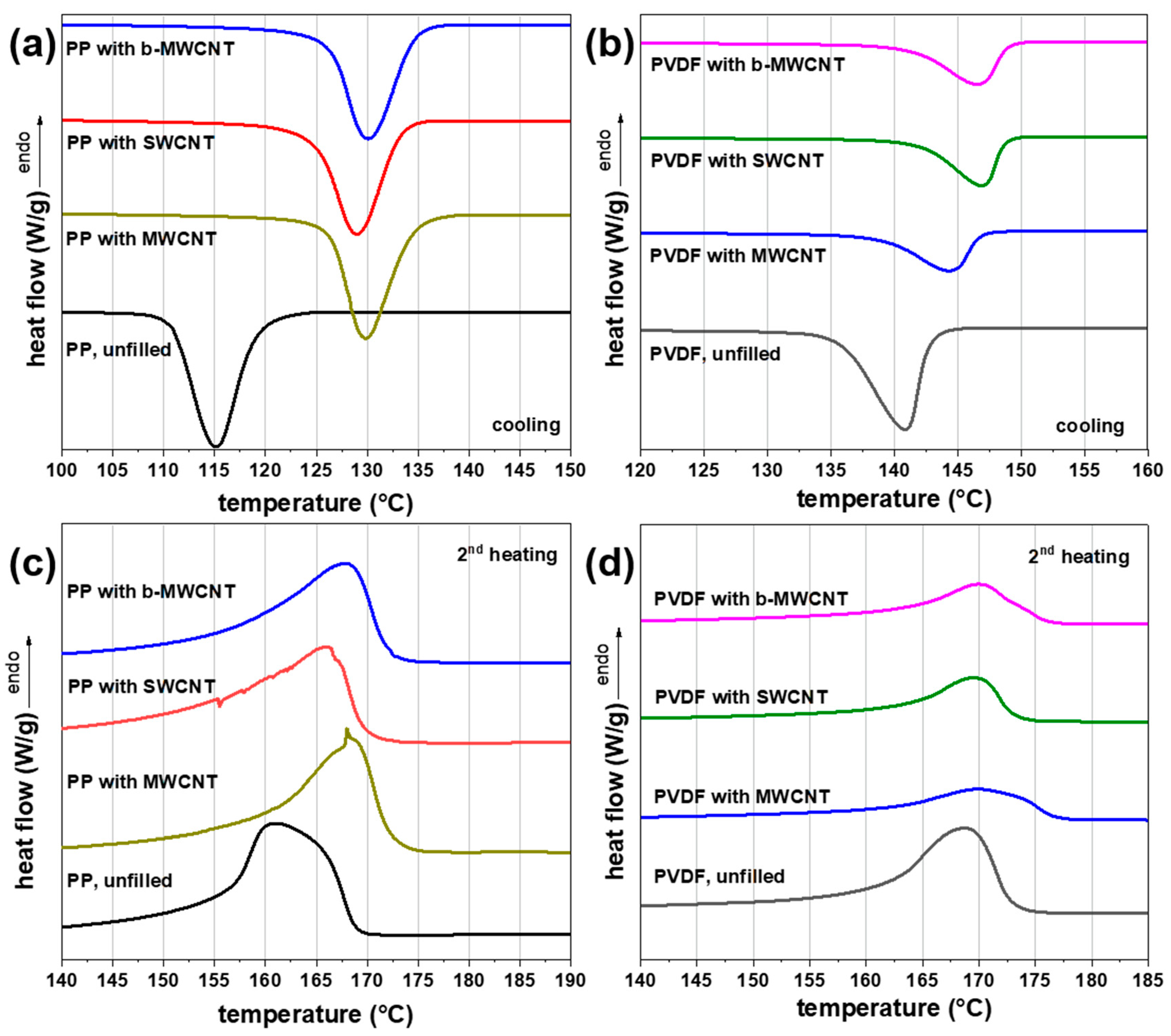
3.4. Effect of CNT Type on Crystalline Morphology
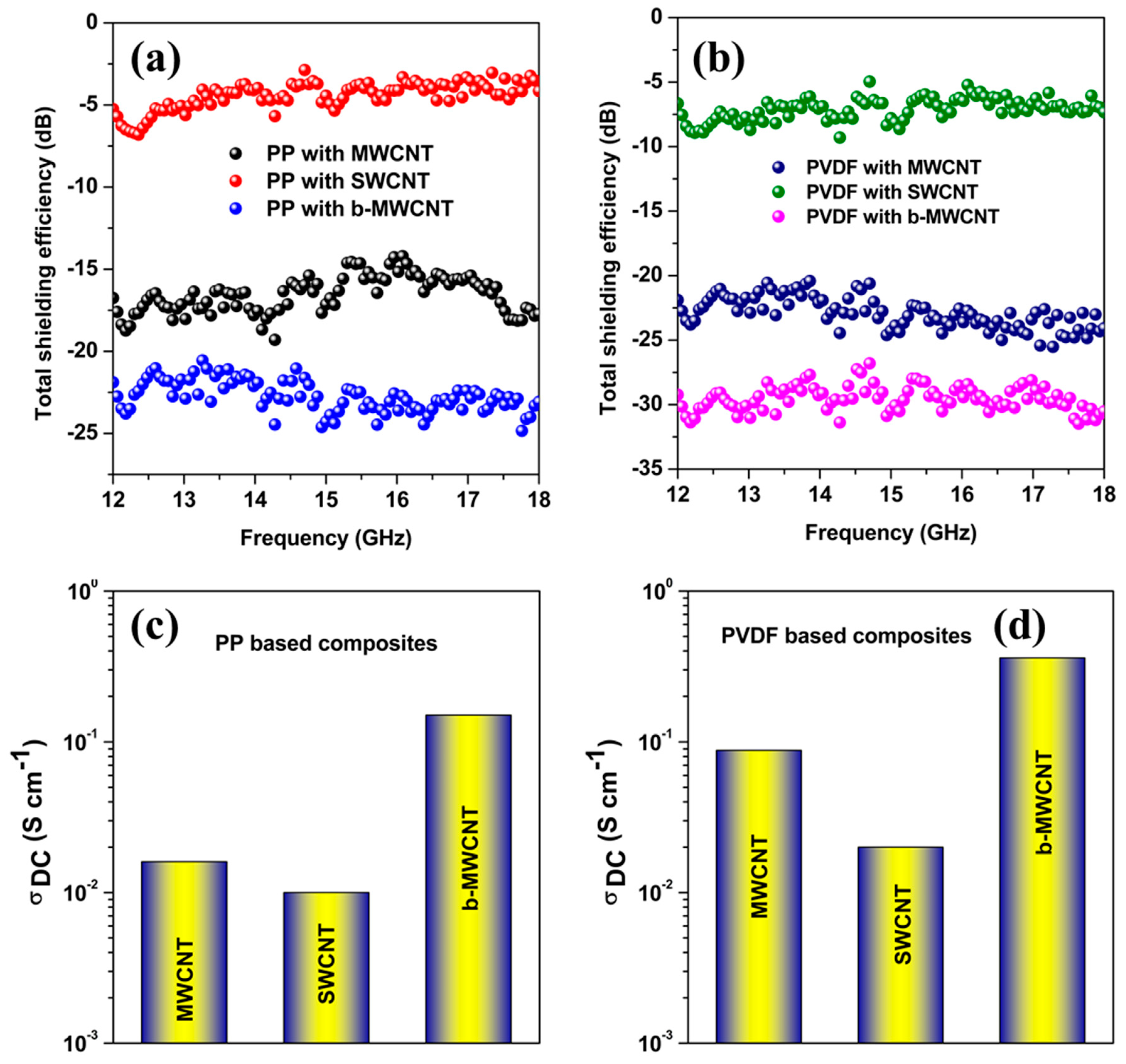
For semicrystalline polymers like PP and PVDF, the degree of crystallization are important factors determining the structural properties of the matrix. It is well known, that nanofillers can influence the crystallization significantly [17,32,33]. Hence the crystallization and melting behavior of the different composites was investigated using DSC (Figure 6) and the obtained parameters are listed in Table 1. It was observed that the incorporation of different types of CNTs into the matrix alters the crystallization and melting temperatures significantly. In addition, the crystallinity changed upon CNT addition. However, the changes are more prominent in PVDF than PP based composites.
Incorporation of three kinds of CNTs in PVDF and PP composites results in an increase of the crystallization temperature, melting temperature, and a decrease in crystallinity (Table 1). The increases in the crystallization temperature Tc,max were more pronounced for SWCNT and b-MWCNT than for the incorporation of MWCNT in PVDF composites. In PP composites, the SWCNTs had the lowest increase in crystallization temperature Tc,max compared to the other CNT types. This could be related to the very poor distribution of SWCNT in the PP matrix.
It is well-known that CNTs are forced out in the amorphous phase when the polymer matrix crystallizes. Thus, as higher matrix crystallinity, the CNTs are forced in a less spacious amorphous phase and as higher is the local concentration in that phase. This was shown as well for PP as for PVDF. In this comparison, PP has the lower crystallinity than PVDF. Calculating the amount of amorphous phase and relating the filling level of 2 wt % in the nanocomposite only to the amorphous phase, relative CNT loadings of 3.3–3.4 wt % (in PP) or 6.0–7.0 wt % (in PVDF) result.
Besides the nature of CNTs, the specific interactions between the CNTs and the polymer also play a significant role. For instance, in PVDF, through CH-π and/or donor–acceptor conjugation, MWCNTs are relatively better dispersed in PVDF than in PP. This resulted in elevated crystallization and melting temperatures in PVDF based composites [34]. It is well known that PVDF exists in the different crystal structure and interestingly from the FT-IR experiments we have observed the existence of β-phase in PVDF based composites (Figure 7) [34]. Among the different CNTs, b-MWCNT facilitated in the formation of β-PVDF. This is manifested from the appearance of a new peak centered around 840 cm−1 in case of PVDF based composites. It is evident from the above discussion that besides the CNT type, the nature of the polymer in general and specific interactions in particular controls the overall crystalline morphology in the polymeric composites.

3.5. EMI Shielding

EM shielding efficiency is the ability to attenuate incident EM waves, which can be measured by the logarithmic proportion of incident and transmitted power [35]. In this study, the total shielding effectiveness (SET) in 12–18 GHz frequency region was calculated by using the scattering parameters, which are specifically accessible from the VNA (vector network analyzer) [36]. Figure 8a,b shows the SET of various nanocomposites in the Ku band frequency, where SET = 1 | S 12 | 2 , where S21/S21 is the forward/reverse transmitted coefficient [37]. It is observed that the SET is strongly dependent on the structural properties of the CNTs. As, neat PP and PVDF are transparent to EM waves so, the shielding efficiency is primarily originated from the conducting network of the CNTs inside the insulating matrix. In this context, it is well known that the existence of a well interconnected conducting network is crucial rather than higher bulk electrical conductivity of the fillers for effective shielding. The obviously remaining agglomerates of SWCNTs at different length scales resulted in its composite in the lowest direct current (DC) electrical conductivity when compared with the other CNTs (Figure 8c,d). [38] Both MWCNTs and b-MWCNT are capable of rendering higher shielding efficiency by forming better interconnected networks in their composites.
PVDF through specific interactions led to the more effective dispersion of CNTs in the composites and resulted in higher shielding effectiveness when compared with PP based composites. Among the different CNTs, b-MWCNT showed the highest shielding presumably due to a better-interconnected network in the host. This observation begins to suggest that the structural properties of CNTs control the overall shielding effectiveness in the composites besides the nature of the polymeric host.
The literature suggests that surface reflection is the dominant mechanism for conducting materials due to impedance miss match [39,40]. However, in our study the shielding efficiency decays as a function of film thickness (see Table 2). This decrease in shielding efficiency attributes to a reduction in the conducting mesh size, which is a significant contributor to the absorption through multiple reflections.
Theoretical knowledge further reinforced our understanding that absorption through dissipation of incident energies through dielectric heating has an impressive impact [36,41]. Interactions with dielectric materials can be comprised of the conductivity loss and various polarization losses [42]. Here conductivity losses arise from spillage current in CNTs and polymer interfaces [43]. Due to its small size and various interactions with the matrix, CNTs are fully fenced by PVDF. So, during interaction with EM waves, the movement of free charge carriers occurs through electron hopping and that results some conductivity losses.
However, polarization losses depend on the many factors although; only a few are active in the higher frequency region. Generally, dipoles of the dielectric materials will try to orient themselves by the interaction with the electric field vector of the incident EM waves [44]. However, in the GHz frequency region, the responding time for the preferred orientation of the active dipoles of the shielding materials is very less. As a result, dipoles collide with each other, which actually leads to the dissipation of energies through dielectric heat generation. Here, the presence of the polar β phase in the PVDF crystal structure, efficiently accounted for the polarization losses through dipoles orientation [29]. In addition, the enhancement in the polar β crystal also maximizes the overall losses and the total shielding efficiency.
On the other hand, charge accumulation due to the Maxwell–Wagner polarization mechanism is also helping in elevating the shielding efficiency. Interfacial polarization occurs when materials with a different dielectric constant are present in the system and therefore requires different voltage gradients to trans-conduct a current of constant density [45]. As a result, we assumed that some sort of free charge is accumulated at the inner dielectric boundary layers of PVDF due to the Maxwell–Wagner interfacial polarization. In addition, the donor–acceptor conjugation with the matrix and fillers also be effective for enhancing such polarization [29]. As a whole the effect of conductivity losses and polarization losses led to absorption driven shielding in the composites. The better dispersion of b-MWCNT in contrast with the other CNTs resulted in overall higher shielding efficiency.
The results thus obtained further gave motivation to design multi-layer assembly of the different nanocomposites to achieve more effective shielding (Figure 9). Three distinct layers from the same composites were stacked and were measured for its shielding effectiveness in 12–18 GHz frequency. Thereby, the sequence of layers was modified by using all three nanocomposites with 2 wt % CNTs of the different types. Table 3 shows an elevation in shielding effectiveness when comparing the three-layer composites with 0.9 mm thickness with the single layer composites with 1 mm thickness. This effect might be due to the charge storing capacity of the layers due to the variations in the dielectric materials [46]. Again, in case of PVDF based composites the shielding efficiency was higher when compared with PP based composites. On the other hand, the sequence of layering in both of the cases had little effect on the shielding efficiency (Table 3). The highest values were for both matrices observed when the stacking was done in the order MWCNT + SWCNT + b-MWCNT.

4. Conclusions

PP and PVDF based composites were prepared by melt-mixing using different CNTs (MWCNT, SWCNT, and b-MWCNT) having different structural properties so as to understand the effects of the matrix and CNT type on the overall shielding performance. Their dispersion state, melt viscosity, electrical conductivity, and electromagnetic shielding ability in 12–18 GHz frequency region were thoroughly evaluated. We observed that the polar semi-crystalline host (here PVDF) favors better dispersion of CNTs in the composites when compared with the non-polar host (here PP). The branched CNT (b-MWCNT) resulted not only in best dispersion and highest influences on the crystallization behavior of the respective matrix, but also in higher shielding effectiveness when compared with other CNTs irrespective of the host matrix in the composites. This was especially evident in the PVDF matrix, where the interconnected network of CNTs acts as a fence in the composites to attenuate the incoming EM radiation through multiple internal reflections. Thereby, the type of CNTs controlled the overall shielding performance. In addition, by stacking three individual layers with only 0.3 mm thickness, in PVDF composites with only 2 wt % CNT loading, 99.999% of the incoming EM radiation can be attenuated. Thus, layered assemblies containing nanocomposites seems to be an effective way to enhance EM shielding capability.

Author Contributions

P.P. and S.B. (Suryasarathi Bose) designed the experiments and shared their inputs. S.B. (Sourav Biswas), P.R. and T.S.M. worked on the experiments and executed the work. B.K. evaluated and analyzed the data. All authors have read and agreed to the published version of the manuscript.

Funding

This research received no external funding.

Acknowledgments

The authors would like to thank the AFMM and CeNSE facilities at IISc for various characterizations. The authors thank ANS (Applied NanoStructured Solutions LLC, Baltimore, MD, USA) for supplying the branched MWCNT CNS-PEG material.

Conflicts of Interest

The authors declare no competing financial interest.

References

  1. Shahzad, F.; Alhabeb, M.; Hatter, C.B.; Anasori, B.; Hong, S.M.; Koo, C.M.; Gogotsi, Y. Electromagnetic interference shielding with 2D transition metal carbides (MXenes). Science 2016, 353, 1137–1140. [Google Scholar] [CrossRef] [Green Version]
  2. Ding, D.; Wang, Y.; Li, X.; Qiang, R.; Xu, P.; Chu, W.; Han, X.; Du, Y. Rational design of core-shell Co@ C microspheres for high-performance microwave absorption. Carbon 2017, 111, 722–732. [Google Scholar] [CrossRef]
  3. Bhattacharjee, Y.; Arief, I.; Bose, S. Recent trends in multi-layered architectures towards screening electromagnetic radiation: Challenges and perspectives. J. Mater. Chem. C 2017, 5, 7390–7403. [Google Scholar] [CrossRef]
  4. Biswas, S.; Panja, S.S.; Bose, S. Tailored distribution of nanoparticles in bi-phasic polymeric blends as emerging materials for suppressing electromagnetic radiation: Challenges and prospects. J. Mater. Chem. C 2018, 6, 3120–3142. [Google Scholar] [CrossRef]
  5. Geetha, S.; Satheesh Kumar, K.; Rao, C.R.; Vijayan, M.; Trivedi, D. EMI shielding: Methods and materials—A review. J. Appl. Polym. Sci. 2009, 112, 2073–2086. [Google Scholar] [CrossRef]
  6. Chung, D. Electromagnetic interference shielding effectiveness of carbon materials. Carbon 2001, 39, 279–285. [Google Scholar] [CrossRef]
  7. Thomassin, J.-M.; Jerome, C.; Pardoen, T.; Bailly, C.; Huynen, I.; Detrembleur, C. Polymer/carbon based composites as electromagnetic interference (EMI) shielding materials. Mater. Sci. Eng. R 2013, 74, 211–232. [Google Scholar] [CrossRef]
  8. Al-Saleh, M.H.; Sundararaj, U. Electromagnetic interference shielding mechanisms of CNT/polymer composites. Carbon 2009, 47, 1738–1746. [Google Scholar] [CrossRef]
  9. Biswas, S.; Kar, G.P.; Bose, S. Simultaneous Improvement in Structural Properties and Microwave Shielding of Polymer Blends with Carbon Nanotubes. ChemNanoMat 2016, 2, 140–148. [Google Scholar] [CrossRef]
  10. Arjmand, M.; Chizari, K.; Krause, B.; Pötschke, P.; Sundararaj, U. Effect of synthesis catalyst on structure of nitrogen-doped carbon nanotubes and electrical conductivity and electromagnetic interference shielding of their polymeric nanocomposites. Carbon 2016, 98, 358–372. [Google Scholar] [CrossRef]
  11. Ren, F.; Yu, H.; Wang, L.; Saleem, M.; Tian, Z.; Ren, P. Current progress on the modification of carbon nanotubes and their application in electromagnetic wave absorption. RSC Adv. 2014, 4, 14419–14431. [Google Scholar] [CrossRef]
  12. Zhao, B.; Zhao, C.; Li, R.; Hamidinejad, S.M.; Park, C.B. Flexible, Ultrathin, and High-Efficiency Electromagnetic Shielding Properties of Poly (Vinylidene Fluoride)/Carbon Composite Films. ACS Appl. Mater. Interfaces 2017, 9, 20873–20884. [Google Scholar] [CrossRef]
  13. Coleman, J.N.; Khan, U.; Blau, W.J.; Gun’ko, Y.K. Small but strong: A review of the mechanical properties of carbon nanotube–polymer composites. Carbon 2006, 44, 1624–1652. [Google Scholar] [CrossRef]
  14. Spitalsky, Z.; Tasis, D.; Papagelis, K.; Galiotis, C. Carbon nanotube–polymer composites: Chemistry, processing, mechanical and electrical properties. Prog. Polym. Sci. 2010, 35, 357–401. [Google Scholar] [CrossRef]
  15. Xie, X.-L.; Mai, Y.-W.; Zhou, X.-P. Dispersion and alignment of carbon nanotubes in polymer matrix: A review. Mater. Sci. Eng. R 2005, 49, 89–112. [Google Scholar] [CrossRef]
  16. Eswaraiah, V.; Sankaranarayanan, V.; Ramaprabhu, S. Inorganic nanotubes reinforced polyvinylidene fluoride composites as low-cost electromagnetic interference shielding materials. Nanoscale Res. Lett. 2011, 6, 137. [Google Scholar] [CrossRef] [PubMed] [Green Version]
  17. Krause, B.; Pötschke, P.; Ilin, E.; Predtechenskiy, M. Melt mixed SWCNT-polypropylene composites with very low electrical percolation. Polymer 2016, 98, 45–50. [Google Scholar] [CrossRef]
  18. Krause, B.; Boldt, R.; Pötschke, P. A method for determination of length distributions of multiwalled carbon nanotubes before and after melt processing. Carbon 2011, 49, 1243–1247. [Google Scholar] [CrossRef]
  19. Ke, K.; Pötschke, P.; Jehnichen, D.; Fischer, D.; Voit, B. Achieving β-phase poly (vinylidene fluoride) from melt cooling: Effect of surface functionalized carbon nanotubes. Polymer 2014, 55, 611–619. [Google Scholar] [CrossRef]
  20. Gaur, U.; Wunderlich, B. Heat capacity and other thermodynamic properties of linear macromolecules. IV. Polypropylene. J. Phys. Chem. Ref. Data 1981, 10, 1051–1064. [Google Scholar] [CrossRef] [Green Version]
  21. Gaur, U.; Lau, S.-f.; Wunderlich, B.B.; Wunderlich, B. Heat capacity and other thermodynamic properties of linear macromolecules. VIII. Polyesters and polyamides. J. Phys. Chem. Ref. Data 1983, 12, 65–89. [Google Scholar] [CrossRef] [Green Version]
  22. Arjmand, M.; Mahmoodi, M.; Gelves, G.A.; Park, S.; Sundararaj, U. Electrical and electromagnetic interference shielding properties of flow-induced oriented carbon nanotubes in polycarbonate. Carbon 2011, 49, 3430–3440. [Google Scholar] [CrossRef]
  23. Dresselhaus, M.S.; Jorio, A.; Hofmann, M.; Dresselhaus, G.; Saito, R. Perspectives on carbon nanotubes and graphene Raman spectroscopy. Nano Lett. 2010, 10, 751–758. [Google Scholar] [CrossRef] [PubMed]
  24. Dresselhaus, M.S.; Dresselhaus, G.; Saito, R.; Jorio, A. Raman spectroscopy of carbon nanotubes. Phys. Rep. 2005, 409, 47–99. [Google Scholar] [CrossRef]
  25. Socher, R.; Krause, B.; Müller, M.T.; Boldt, R.; Pötschke, P. The influence of matrix viscosity on MWCNT dispersion and electrical properties in different thermoplastic nanocomposites. Polymer 2012, 53, 495–504. [Google Scholar] [CrossRef]
  26. Alig, I.; Pötschke, P.; Lellinger, D.; Skipa, T.; Pegel, S.; Kasaliwal, G.R.; Villmow, T. Establishment, morphology and properties of carbon nanotube networks in polymer melts. Polymer 2012, 53, 4–28. [Google Scholar] [CrossRef]
  27. Krause, B.; Mende, M.; Petzold, G.; Boldt, R.; Pötschke, P. Characterization of dispersability of industrial nanotube materials and their length distribution before and after melt processing. In Carbon Nanotube-Polymer Composites; Tasis, D., Ed.; Royal Society of Chemistry: Cambridge, UK, 2013; pp. 212–233. [Google Scholar]
  28. Baskaran, D.; Mays, J.W.; Bratcher, M.S. Noncovalent and nonspecific molecular interactions of polymers with multiwalled carbon nanotubes. Chem. Mater. 2005, 17, 3389–3397. [Google Scholar] [CrossRef] [Green Version]
  29. Yuan, J.-K.; Yao, S.-H.; Dang, Z.-M.; Sylvestre, A.; Genestoux, M.; Bai1, J. Giant dielectric permittivity nanocomposites: Realizing true potential of pristine carbon nanotubes in polyvinylidene fluoride matrix through an enhanced interfacial interaction. J. Phys. Chem. C 2011, 115, 5515–5521. [Google Scholar] [CrossRef]
  30. Du, F.; Scogna, R.C.; Zhou, W.; Brand, S.; Fischer, J.E.; Winey, K.I. Nanotube networks in polymer nanocomposites: Rheology and electrical conductivity. Macromolecules 2004, 37, 9048–9055. [Google Scholar] [CrossRef]
  31. Pötschke, P.; Fornes, T.; Paul, D. Rheological behavior of multiwalled carbon nanotube/polycarbonate composites. Polymer 2002, 43, 3247–3255. [Google Scholar] [CrossRef]
  32. Wang, J.; Kazemi, Y.; Wang, S.; Hamidinejad, M.; Mahmud, M.B.; Pötschke, P.; Park, C.B. Enhancing the electrical conductivity of PP/CNT nanocomposites through crystal-induced volume exclusion effect with a slow cooling rate. Compos. Part B: Eng. 2020, 183, 107663. [Google Scholar] [CrossRef]
  33. Gebrekrstos, A.; Biswas, S.; Menon, A.V.; Madras, G.; Pötschke, P.; Bose, S. Multi-layered stack consisting of PVDF nanocomposites with flow-induced oriented MWCNT structure can supress electromagnetic radiation. Compos. Part B: Eng. 2019, 166, 749–757. [Google Scholar] [CrossRef]
  34. Sharma, M.; Madras, G.; Bose, S. Process induced electroactive β-polymorph in PVDF: Effect on dielectric and ferroelectric properties. Phys. Chem. Chem. Phys. 2014, 16, 14792–14799. [Google Scholar] [CrossRef] [PubMed]
  35. Ghosh, S.; Remanan, S.; Mondal, S.; Ganguly, S.; Das, P.; Singha, N.; Das, N.C. An approach to prepare mechanically robust full IPN strengthened conductive cotton fabric for high strain tolerant electromagnetic interference shielding. Chem. Eng. J. 2018, 344, 138–154. [Google Scholar] [CrossRef]
  36. Biswas, S.; Arief, I.; Panja, S.S.; Bose, S. Absorption-Dominated Electromagnetic Wave Suppressor Derived from Ferrite-Doped Cross-Linked Graphene Framework and Conducting Carbon. ACS Appl. Mater. Interfaces 2017, 9, 3030–3039. [Google Scholar] [CrossRef] [PubMed]
  37. Arief, I.; Biswas, S.; Bose, S. Tuning the Shape Anisotropy and Electromagnetic Screening Ability of Ultrahigh Magnetic Polymer and Surfactant-Capped FeCo Nanorods and Nanocubes in Soft Conducting Composites. ACS Appl. Mater. Interfaces 2016, 8, 26285–26297. [Google Scholar] [CrossRef] [PubMed]
  38. Krause, B.; Barbier, C.; Kunz, K.; Pötschke, P. Comparative study of singlewalled, multiwalled, and branched carbon nanotubes melt mixed in different thermoplastic matrices. Polymer 2018, 159, 75–85. [Google Scholar] [CrossRef]
  39. Biswas, S.; Panja, S.S.; Bose, S. Unique Multilayered Assembly Consisting of “Flower-Like” Ferrite Nanoclusters Conjugated with MWCNT as Millimeter Wave Absorbers. J. Phys. Chem. C 2017, 121, 13998–14009. [Google Scholar] [CrossRef]
  40. Liu, Z.; Bai, G.; Huang, Y.; Ma, Y.; Du, F.; Li, F.; Guo, T.; Chen, Y. Reflection and absorption contributions to the electromagnetic interference shielding of single-walled carbon nanotube/polyurethane composites. Carbon 2007, 45, 821–827. [Google Scholar] [CrossRef]
  41. Biswas, S.; Panja, S.S.; Bose, S. Physical Insight into the Mechanism of Electromagnetic Shielding in Polymer Nanocomposites Containing Multiwalled Carbon Nanotubes and Inverse-Spinel Ferrites. J. Phys. Chem. C 2018, 122, 19425–19437. [Google Scholar] [CrossRef]
  42. Liu, W.; Liu, J.; Yang, Z.; Ji, G. Extended Working Frequency of Ferrites by Synergistic Attenuation through a Controllable Carbothermal Route Based on Prussian Blue Shell. ACS Appl. Mater. Interfaces 2018, 10, 28887–28897. [Google Scholar] [CrossRef] [PubMed]
  43. Wen, B.; Cao, M.-S.; Hou, Z.-L.; Song, W.-L.; Zhang, L.; Lu, M.-M.; Jin, H.-B.; Fang, X.-Y.; Wang, W.-Z.; Yuan, J. Temperature dependent microwave attenuation behavior for carbon-nanotube/silica composites. Carbon 2013, 65, 124–139. [Google Scholar] [CrossRef]
  44. Zhao, B.; Guo, X.; Zhao, W.; Deng, J.; Shao, G.; Fan, B.; Bai, Z.; Zhang, R. Yolk–shell Ni@ SnO2 composites with a designable interspace to improve the electromagnetic wave absorption properties. ACS Appl. Mater. Interfaces 2016, 8, 28917–28925. [Google Scholar] [CrossRef] [PubMed]
  45. Prodromakis, T.; Papavassiliou, C. Engineering the Maxwell–Wagner polarization effect. Appl. Surf. Sci. 2009, 255, 6989–6994. [Google Scholar] [CrossRef]
  46. Li, Y.; Shen, B.; Yi, D.; Zhang, L.; Zhai, W.; Wei, X.; Zheng, W. The influence of gradient and sandwich configurations on the electromagnetic interference shielding performance of multilayered thermoplastic polyurethane/graphene composite foams. Compos. Sci. Technol. 2017, 138, 209–216. [Google Scholar] [CrossRef]
Figure 1. SEM micrograph of fillers: (a) multiwalled carbon nanotubes (MWCNT) NC7000, (b) singlewalled carbon nanotubes (SWCNT) Tuball, and (c) branched multiwalled carbon nanotubes (b-MWCNT).
Jcs 04 00009 g001
Figure 2. Raman spectra of the different carbon nanotube (CNT) types.
Jcs 04 00009 g002
Figure 3. Light microscopy image of a thin section of polymer/2 wt % CNT composites: PP with MWCNT (a), PP with SWCNT (b), PP with b-MWCNT (c), PVDF with MWCNT (d), PVDF with SWCNT (e), and PVDF with b-MWCNT (f).
Jcs 04 00009 g003
Figure 4. SEM micrographs of the cyo-fracture surface of polymer/2 wt % CNT composites: PP with MWCNT (a), PP with SWCNT (b), PP with b-MWCNT (c), PVDF with MWCNT (d), PVDF with SWCNT (e), and PVDF with b-MWCNT (f).
Jcs 04 00009 g004
Figure 5. (a,b) complex viscosity Iη*I of PP and PVDF based composites, (c,d) storage modulus G′ of PP and PVDF based composites. All composites contain 2 wt % CNTs.
Jcs 04 00009 g005
Figure 6. Differential scanning calorimetry (DSC) cooling cycles for PP and PVDF based composites (a,b), DSC heating cycles for PP and PVDF based composites (c,d). All composites contain 2 wt % CNTs.
Jcs 04 00009 g006
Figure 7. FT-IR spectra of PP based composites (a) and PVDF based composites (b) All composites contain 2 wt % CNT.
Jcs 04 00009 g007
Figure 8. Total electromagnetic shielding efficiency of samples with a thickness of 1 mm for (a) PP based and (b) PVDF based composites, and (c) DC electrical conductivity of PP and (d) PVDF based composites. All composites contain 2 wt % CNT.
Jcs 04 00009 g008
Figure 9. Shielding effectiveness of multi-layered stacks of PP with MWCNT + SWCNT + b-MWCNT and PVDF with MWCNT + SWCNT + b-MWCNT All composites contain 2 wt % CNT. Stack thickness: 0.9 mm.
Jcs 04 00009 g009
Table 1. DSC melting and crystallization temperatures and crystallinity.
CompositionCrystallization Temperature at Maximum (Tc,max; °C)Melting Temperature Tm (°C)Crystallinity (%)
PP (processed)115.6160.842.0
PP + 2 wt % MWCNT129.8168.041.3
PP + 2 wt % SWCNT129.0166.040.0
PP + 2 wt % b-MWCNT130.0167.639.7
PVDF (processed) [42]140.8168.675.0
PVDF + 2 wt % MWCNT [42]144.3169.966.7
PVDF + 2 wt % SWCNT [42]146.9169.568.9
PVDF + 2 wt % b-MWCNT [42]146.6170.071.5
Table 2. Shielding effectiveness (SET,@ 18 GHz) of various composites with thickness variation.
CompositionSET (dB) @
1 mm Thickness
SET (dB) @
0.5 mm Thickness
SET (dB) @
0.3 mm Thickness
PP with MWCNT−18−18−12
PP with SWCNT−4−2−1
PP with b-MWCNT−24−22−17
PVDF with MWCNT−24−20−18
PVDF with SWCNT−7−5−2
PVDF with b-MWCNT−31−24−21
Table 3. Total shielding effectiveness (SET) of multi-layer assemblies of 0.9 mm thickness at 18 GHz of 0.9 mm thickness.
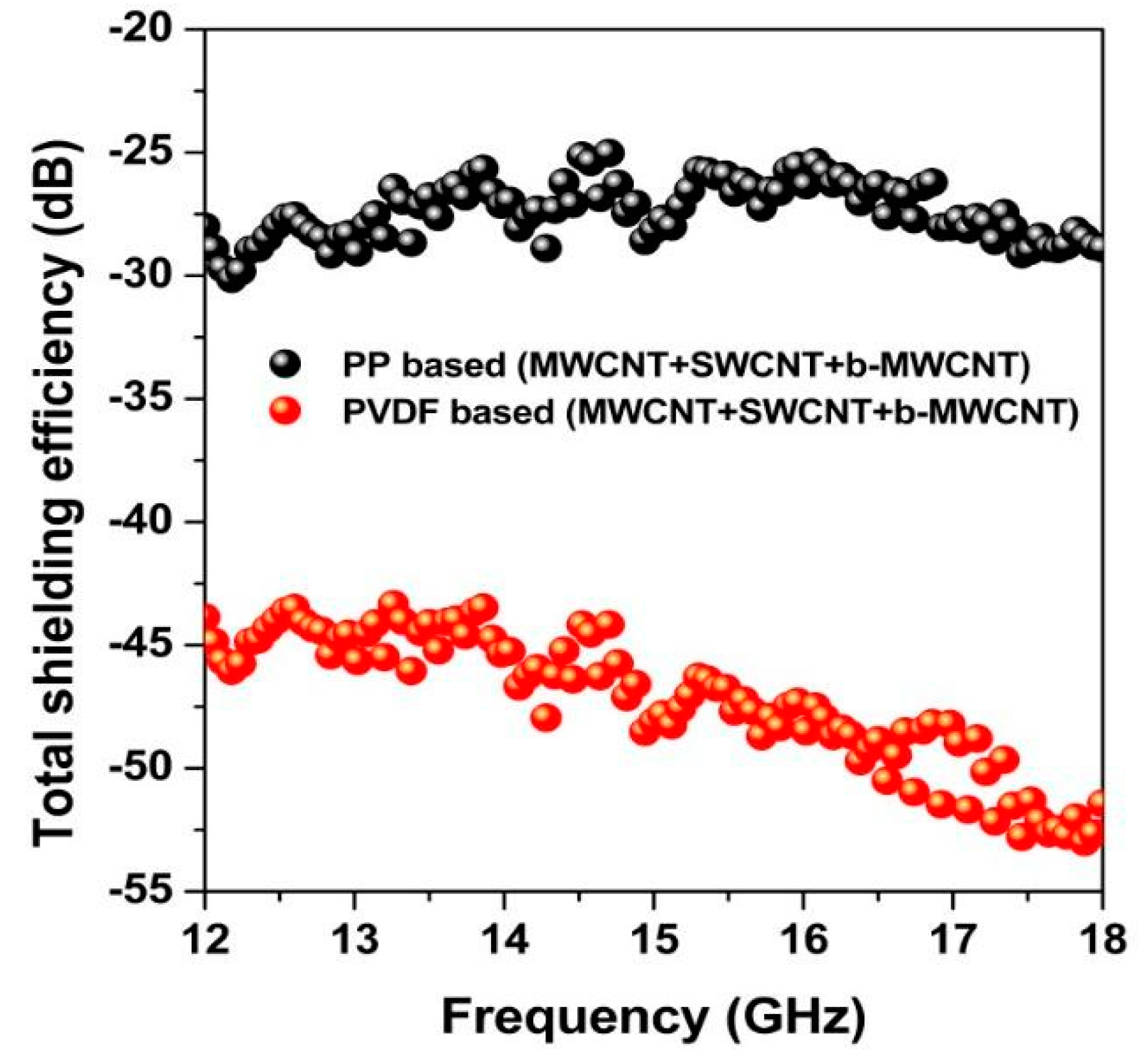
Layer Composition (Each Layer Thickness is 0.3 mm)SET (dB)
PP, MWCNT+ SWCNT + b-MWCNT−29
PP, SWCNT + MWCNT + b-MWCNT−26
PP, SWCNT+ b-MWCNT + MWCNT−27
PVDF, MWCNT+ SWCNT + b-MWCNT−53
PVDF, SWCNT + MWCNT + b-MWCNT−49
PVDF, SWCNT+ b-MWCNT + MWCNT−51

