1. Introduction
Carbon fiber-reinforced polymers (CFRPs) have become indispensable in aerospace, wind energy and high-performance sporting goods thanks to their outstanding stiffness-to-weight ratio and fatigue resistance [
1]. The global CFRC market is forecast to exceed
$20 billion by 2028, expanding at more than 10% per year and outpacing the broader composite sector [
2,
3]. This growth raises two sustainability concerns. First, producing virgin carbon fiber is highly energy-intensive, consuming 200–600 MJ kg
−1, which potentially releases up to 20 kg CO
2 eq. per kilogram of fiber [
4]. Second, end-of-life composites are still predominantly landfilled or incinerated, a trajectory that could generate more than 500 kt of CFRC waste annually by 2050 [
5,
6,
7,
8]. In response, the European waste management hierarchy emphasizes prevention, reuse and recycling before disposal [
9].
Recovering fibers from thermoset composites through pyrolysis or solvolysis is technically feasible, yet the filaments emerge only a few millimeters long with degraded sizing [
10]. When reincorporated through conventional short-fiber routes, such as mechanical grinding [
11], melt compounding or non-woven mats, their mechanical performance is severely curtailed [
12,
13]. Realigning the discontinuous fibers is therefore a pivotal step. Yet for these recycled materials to be adopted in demanding structural applications, it is equally essential to demonstrate that their performance can be reliably predicted using established, computationally efficient design tools.
Aligned Formable Fibre Technology (AFFT
™), formerly known as HiPerDiF [
14], disperses chopped fibers in water, sprays the suspension through a slot nozzle onto a moving belt and removes the liquid under vacuum [
15]; more than 65% of fibers lie within ±3° of the tape axis [
16]. After hot-press consolidation, the prepregs reach fiber-volume fractions close to 40% and, provided the fiber length exceeds the shear-lag critical length [
17], retain 80–90% of the longitudinal modulus of continuous-fiber laminates [
7]. These attributes make AFFT
™ a compelling pathway for closed-loop recycling.
Carbon frames revolutionized bicycle design in the late 1980s, cutting mass by about 1 kg and enabling aerodynamic shaping, corrosion immunity and laminate tailoring for power transfer and ride comfort. Modern race frames exploit anisotropy to fine-tune stiffness, and aerodynamic optimization can increase average speed by roughly 0.5 km/h for the same rider effort [
18]. Extending these benefits to recycled short-fiber composites would open a large, value-added outlet for reclaimed carbon.
To explore this potential, the present work applies Classical Laminate Theory within a finite-element framework to assess whether AFFT
™ laminates can meet the stiffness requirements of a 25 mm diameter top tube for a balance bike, an application representative of real-world bending and torsion loads [
19].
Three consolidation routes, vacuum bagging, compression molding at 7 bar (to simulate autoclave conditions) and at 90 bar, were adopted to represent real-world manufacturing techniques [
20]. They are correlated with fiber-volume fraction, porosity and orthotropic properties. These properties populate a finite-element model in which Classical Laminate Theory supplies the laminate stiffness matrix; a genetic algorithm then searches the stacking-sequence space to minimize the combined bending-and-torsion deflection. Finally, tubes fabricated with the optimized lay-up are tested in three-point bending, providing the first validation of AFFT-based recycled composites for structural cycling applications.
2. Materials and Methods
To investigate the potential of AFFT™ in bicycle frame applications, a structured methodology was developed, encompassing laminate manufacturing, material characterization, computational optimization, and experimental validation on tubular specimens.
2.1. Materials
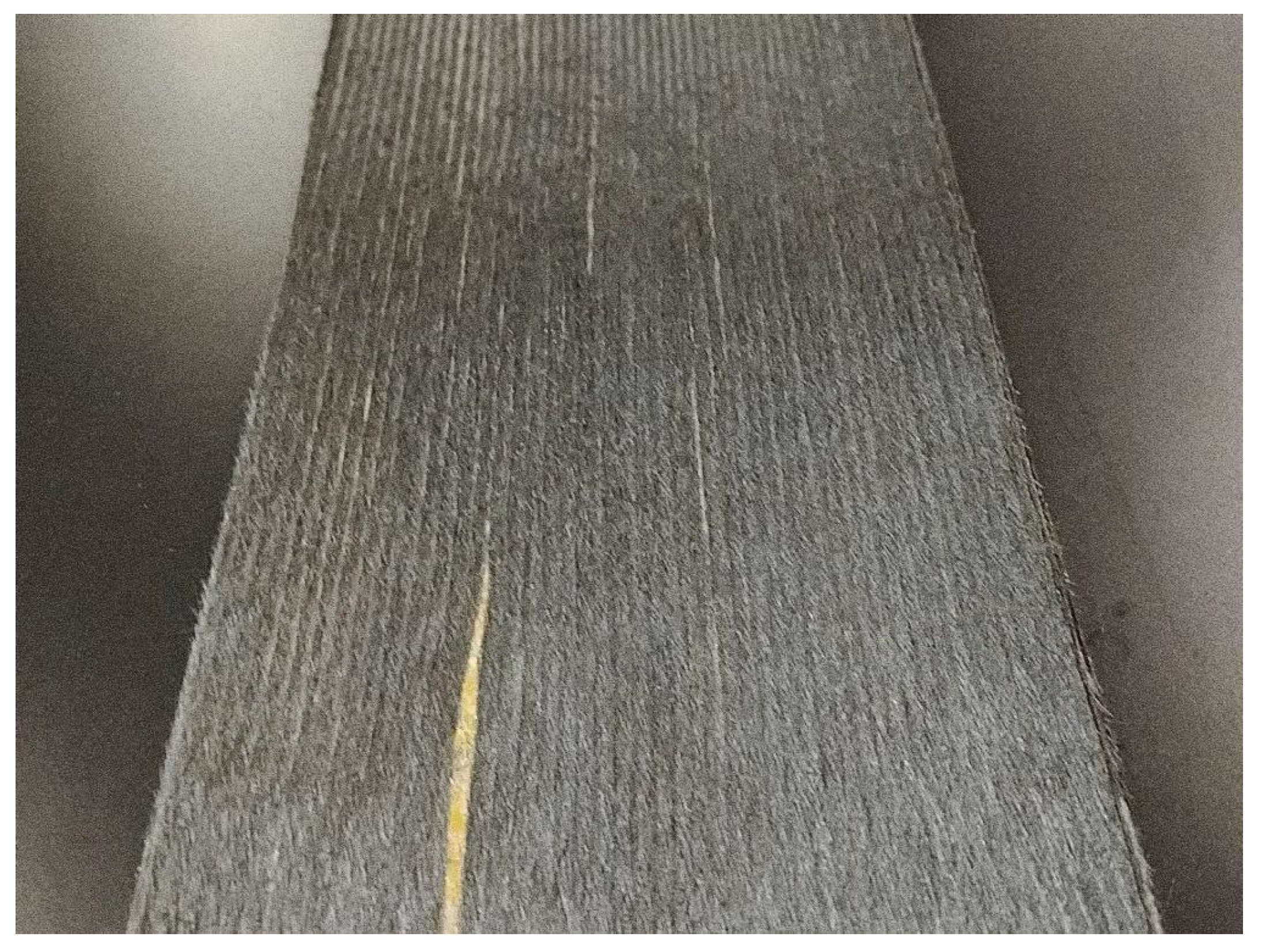
The composite feedstock employed in this study is an Aligned Formable Fibre Technology (AFFT
™) prepreg produced by Lineat Composites (Chepstow, UK) (
Figure 1). The tape contains 4 mm reclaimed standard-modulus carbon fibers realigned within ±3° of the tape axis [
16]. Fiber aerial weight is
, while an SHD VTC401 epoxy film provides
of matrix [
21]. The tape is 100 mm wide, and is supplied frozen (−18 °C) to inhibit premature cross-linking.
Table 1 summarizes the consolidation routes endorsed by the supplier. In all cases the cure schedule used here followed the rapid cycle recommended for the SHD VTC401 epoxy by the manufacturer: heat at 3 °C min
−1 to 100 °C, dwell 1 h, cool at 3 °C min
−1 [
22].
Each cured plate was water-jet cut into rectangular coupons for tensile tests with fibers oriented 0°, 90° and 10° to the loading axis.
Table 2 lists the nominal coupon dimensions used throughout the study; these values reflect a compromise between standardized guidelines, literature recommendations and the 100 mm tape width. Given that the maximum panel size producible with the laboratory hot press was
mm, tensile specimens were proportionally scaled down from the nominal dimensions suggested by ISO 527-4 [
23], preserving the same aspect ratios and gauge geometry. This adjustment ensured that all coupons could be cut from a single, defect-free region of each consolidated plate while maintaining comparability to standard specimens.
The higher width chosen for 90° coupons increases the net load capacity of matrix-dominated specimens, whereas the reduced width for 10° coupons maintains an aspect ratio > 12 to favor uniform shear deformation [
24]. A total of 30 plies was sufficient to exceed the 1 mm thickness threshold for 0° and 10° tests even under CM90 compaction; transverse coupons used 40 plies to offset their lower fiber contribution to strength.
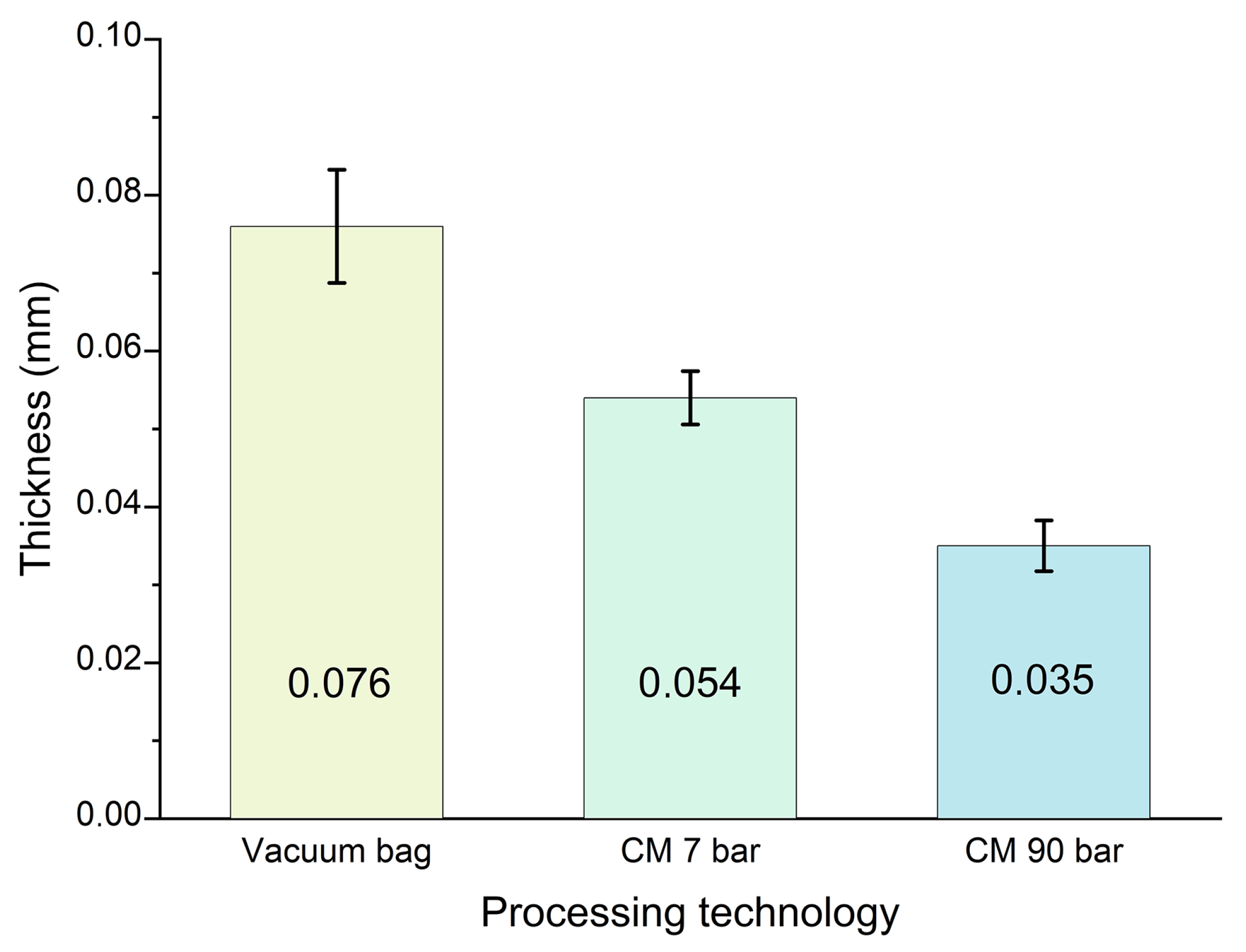
Figure 2 reports the
cured ply thickness measured on laminates produced by the three consolidation routes (defined as total laminate thickness divided by ply count after cure). Raising the compaction pressure clearly densifies the tape stack: the cured ply thickness drops from 76 µm under vacuum bagging to 54 µm at 7 bar and 35 µm at 90 bar. The narrower error bars relative to the standard deviation of five samples for CM7 and CM90 reflect the uniform gap imposed by the mold’s flat plates, whereas the larger scatter under VB is attributed to local pressure variations and resin bleed. These cured-ply values were used as inputs for both the rule of mixtures corrections and the finite-element shell model.
Microscopic Assessment of Laminate Quality
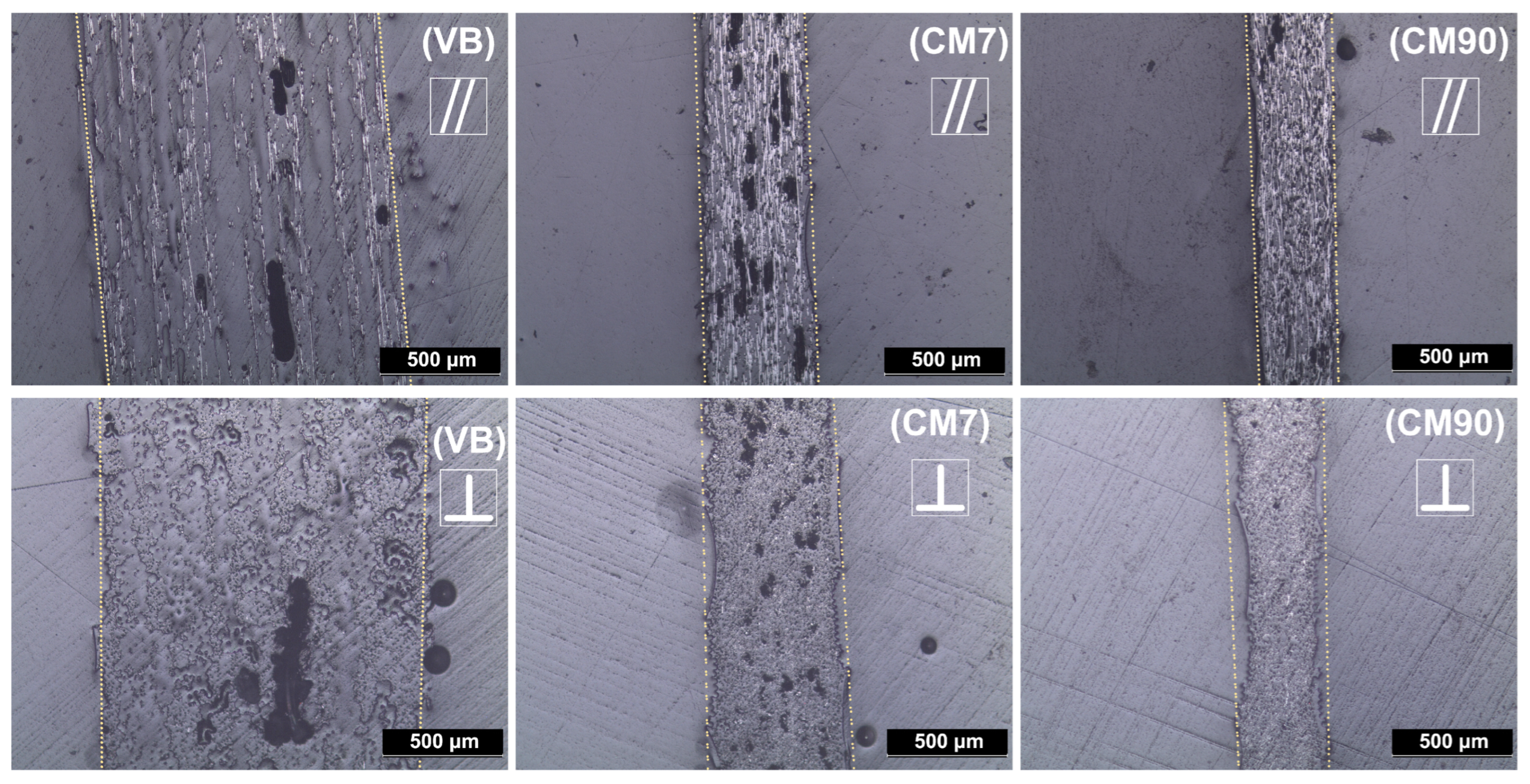
To complement the macroscopic measurements of cured ply thickness, a Leica DM LM optical microscope (Leica Microsystem, Wetzlar, Germany) was employed to evaluate the internal quality of the laminates; the results are shown in
Figure 3. Small coupons were embedded in epoxy resin, then sequentially wet-sanded using P600, P800, P1200 and P2400 SiC papers under water, followed by diamond cloth polishing with 6 µm, 3 µm and 1 µm pastes. Images were captured under reflected light at
magnification in both directions parallel (‖) and perpendicular (⊥) to the fiber alignment.
The sequence VB → CM7 → CM90 clearly illustrates the progressive effect of pressure on laminate consolidation. Void content and resin-rich regions gradually diminish, while the overall laminate thickness decreases, reflecting enhanced fiber packing and resin wet-out. These microstructural features align with the quantitative trends reported in
Figure 2, confirming that increasing compaction pressure yields a denser and more homogeneous microstructure, consistent with the measured cured ply thickness and fiber volume fraction.
2.2. Methods
The experimental campaign supplied the ply data required by Classical Laminate Theory, fed those data to a finite-element optimization loop, and finally verified the predicted performance on composite tubes.
2.2.1. Tensile Testing
Coupons were water-jet cut from the VB, CM7 and CM90 plates, end-tabbed and, where required, speckled for Digital Image Correlation (DIC). Testing was conducted on an Instron 1185R5800 Universal Testing Machine (Instron, Norwood, MA, USA) equipped with a 100 kN Instron 2518 loadcell under displacement control. Longitudinal and 10° coupons were tested at a rate of 2 mm min−1 and monitored by DIC; for transverse coupons a rate of 1 mm min−1 was used and the strain was measured with a video extensometer. For every consolidation route five to eight valid repetitions were recorded. Fiber-volume fraction (burn-off at 500 °C in air) and density (Archimedean method in sunflower oil) were measured on three samples per laminate. Burn-off was used solely to remove the epoxy matrix; 500 °C is below the onset of appreciable oxidative mass loss for the carbon fibers, and no measurable fiber mass loss was detected within the dwell time (within balance resolution).
2.2.2. Optimization Framework and Setup
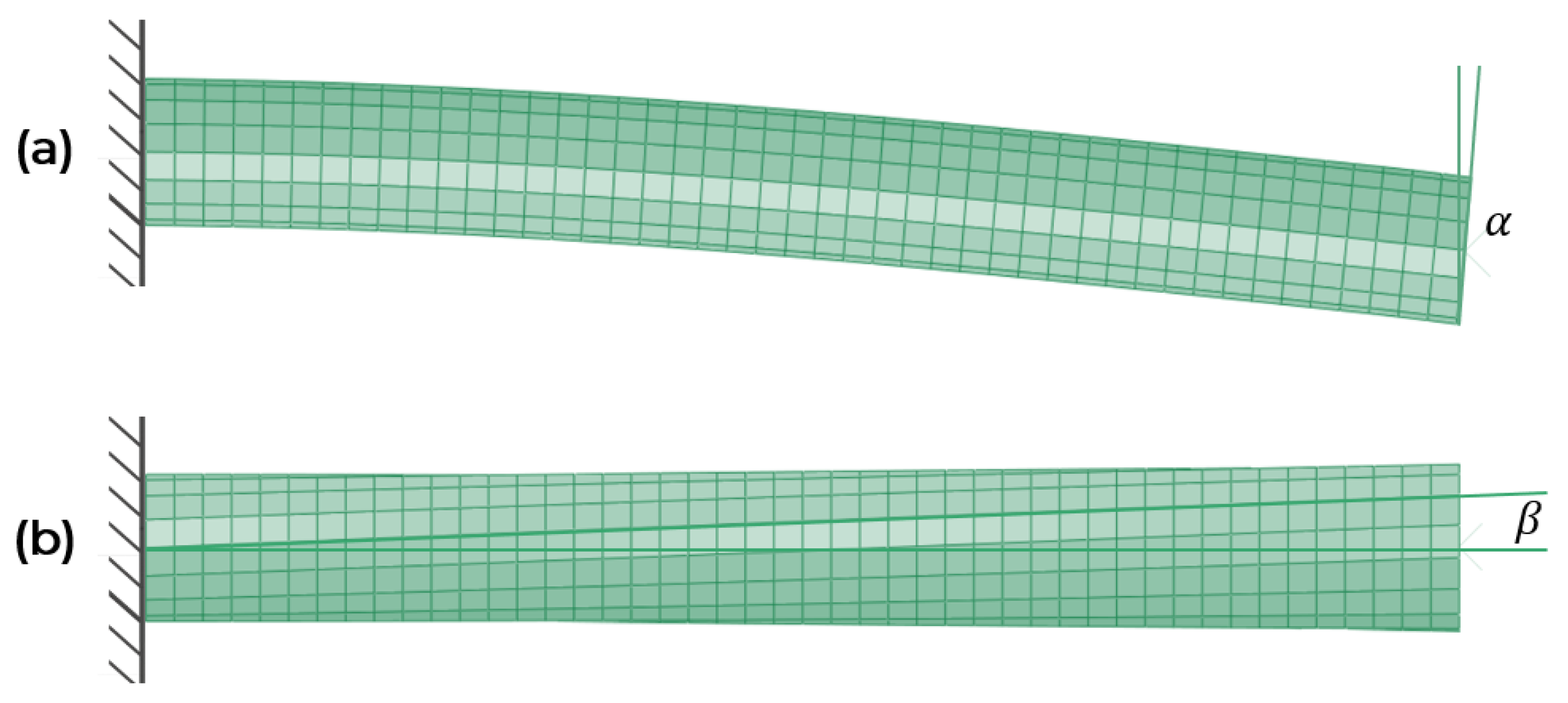
The balance bike top tube was idealized as a thin cylindrical shell, 25 mm in diameter and 225 mm long. Two elementary load cases were studied. A transverse force of 500 N applied at the free end produced a bending rotation
of the vertical face of the free end, as shown in
Figure 4a; the same force acting through a 500 mm lever arm produced a torsional rotation
, as shown in
Figure 4b. Because the laminate is supposed to remain in a linear-elastic regime, the response to any load combination is the sum of the individual responses.
The optimization algorithm presented in this work takes inspiration from and builds upon the optimization framework proposed by Kaveh et al. [
25,
26]. Finite element analyses were performed using Abaqus/Standard 2023 commercial code. The tube was meshed with reduced-integration shell elements (S4R, 3.0 mm average edge size chosen from convergence analysis); orthotropic ply properties from tensile tests were entered through a composite lay-up section, and Classical Laminate Theory provided the laminate stiffness matrix. One tube end was fully constrained; the bending or torsional moment was applied to the opposite end.
The laminate comprised thirty-two plies. Successive groups of four plies shared a common fiber angle, so the stacking sequence was described by eight integers. To limit the possible combinations while retaining sufficient accuracy and save computational time, each integer could take one of seven angles 0°, 15°, 30°, 45°, 60°, 75°, or 90°; within a four-ply block the sign alternated to keep the lay-up balanced. No mirror symmetry was imposed, because a tube that wraps continuously around itself is inherently symmetric about its axis.
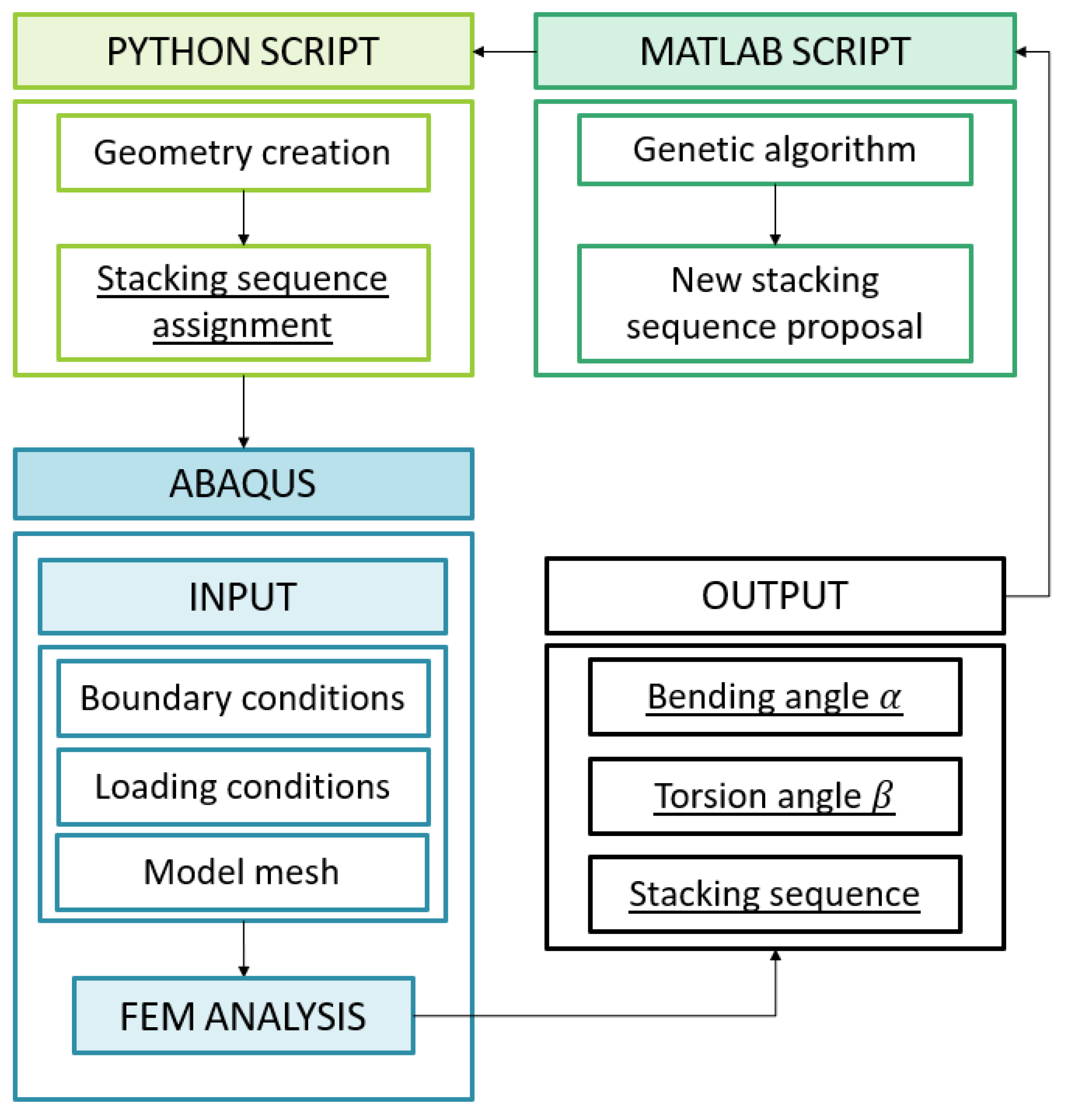
A population of 120 random sequences was generated in MATLAB 2020. For every sequence, a Python script built the Abaqus model (using the Python 2.7 environment embedded in Abaqus 2023), launched two linear analyses (bending and torsion) and returned
and
to MATLAB; this workflow is shown in
Figure 5. The fitness of a sequence was defined as
where
and
refer to a quasi-isotropic laminate. This objective function, although not strictly representative of the optimal fitting function for the design of a tubular bike frame, was chosen for its clarity and considered suitable for this proof-of-concept study. Selection preserving the best 40 solutions of each iteration, crossover of the remaining 80 and mutation of 20% of this part of the population are used for refinement until the best third of sequences showed no improvement for three consecutive generations. Convergence typically required fifteen to twenty generations, and the optimum lay-up reduced
by about 40% relative to the quasi-isotropic reference. That lay-up was adopted for tube manufacture and subsequent bending validation.
2.2.3. Tube Manufacturing and Three-Point Bending
Considering the available manufacturing resources, only VB tubes were manufactured, since manufacturing CM7 and CM90 tubes would require an ad hoc mold for the hot press. A total of 32 plies of AFFT™ tape were manually wrapped around a 25 mm aluminum mandrel in the sequence delivered by the optimization. A 3 min vacuum debulk followed every four plies. The cure cycle for tubes was identical to that of the flat plates (3 °C min−1 to 100 °C, dwell 1 h, cool 3 °C min−1). After cooling, differential thermal contraction released the tube from the mandrel. Three tubes were tested in three-point bending using the same Instron frame, with a span of 180 mm, a loading nose 33.15 mm in diameter, lower supports 15 mm in diameter, and a cross-head speed of 1 mm min−1. The linear slope of the resulting force–displacement curve was compared with the outcome of a finite-element simulation reproducing the experimental three-point bending setup, carried out using the Abaqus/Standard commercial code.
3. Results and Discussion
3.1. Fiber Volume Fraction and Porosity
Burn-off and density analyses indicate that increasing the consolidation pressure enhances the fiber volume fraction while simultaneously reducing void content (
Table 3). Microscopy of polished cross-sections (
Figure 3) supports this observation, showing a progressive reduction of voids and resin-rich pockets as compaction pressure increases. Adequate pressure is therefore essential to achieve full wet-out and to realize the potential stiffness of highly aligned short-fiber tapes.
Porosity values in
Table 3 were derived by comparing the experimental density
with the theoretical density
obtained from burn-off mass fractions, using
. This indirect approach is affected by the connectivity of the void network: surface-connected pores may allow partial fluid infiltration, whereas isolated closed pores remain undetected. As a result, density-based porosity tends to underestimate the true void content and should be interpreted as a non-conservative lower bound. Microscopy reveals a residual population of small voids even at 90 bar, suggesting that the actual porosity of CM90 laminates is higher than the nominal 1% reported in
Table 3. Nevertheless, the relative trend is consistent across methods, confirming a steady reduction in void content with increasing consolidation pressure. The origin of this behavior is inherent to the AFFT
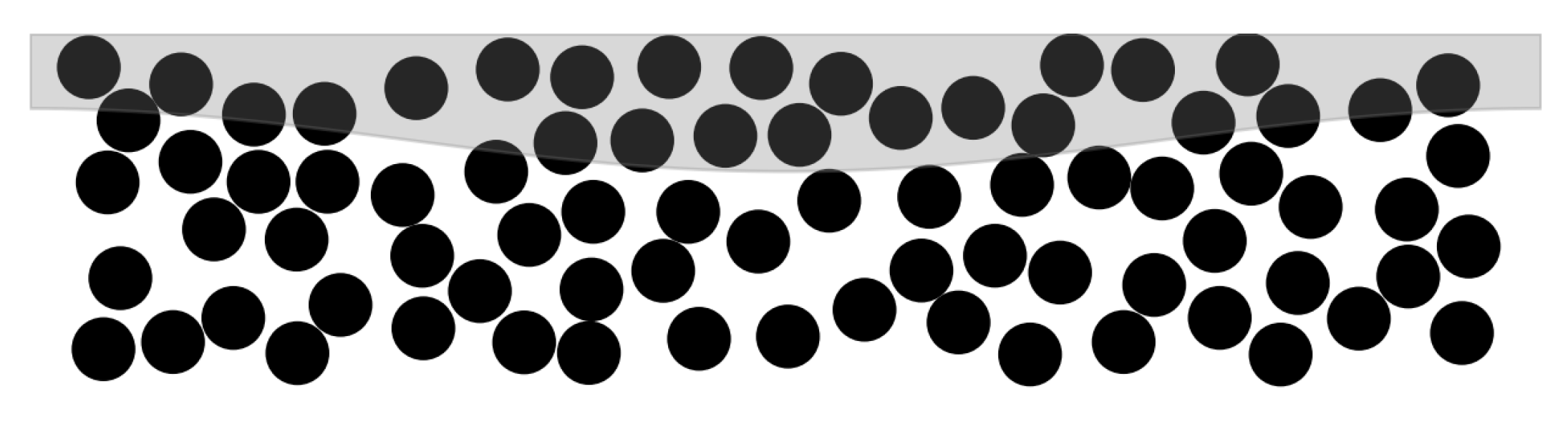
™ manufacturing route (
Figure 6). Fibers are first deposited dry on a moving belt and subsequently coated from above with an epoxy film; resin must therefore percolate downward to impregnate the lowest filaments. Under vacuum bagging, the 1 bar pressure differential is insufficient to force resin through the narrow inter-fiber channels before gelation, leading to entrapped air within the laminate. Compression molding improves impregnation by closing the channels, driving resin through the fiber network, and expelling trapped gas into the breather. Because voids act as compliant inclusions, their persistence in low-pressure laminates limits stiffness and matrix-dominated strengths.
3.2. Mechanical Properties
The present study focuses on validating an elastic–stiffness workflow for AFFT™ laminates. The finite-element model incorporates only the elastic constants , , and , and the optimization targets the combined bending-torsion deflection in the linear regime. Accordingly, tensile tests were performed at 0°, 90°, and 10° off-axis. The 10° configuration provides sensitivity to in-plane shear and enables the determination of through standard off-axis compliance fitting. Strength and failure criteria, as well as compression and dedicated shear tests, are beyond the scope of this work and will be addressed in a follow-on study focused on failure modelling.
To assess the influence of compaction pressure on the elastic response of AFFT
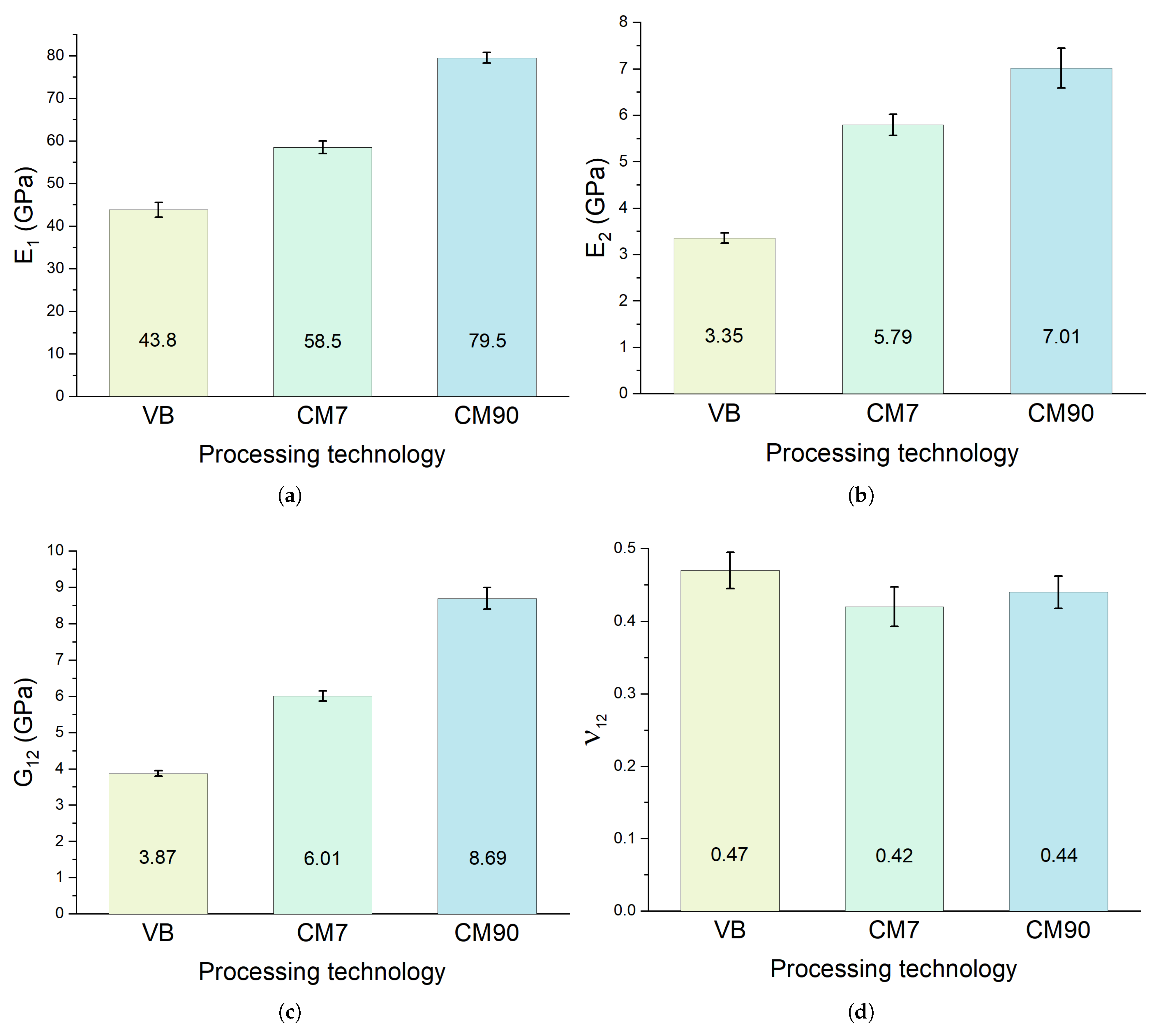
™ laminates, tensile tests were conducted on specimens processed under VB, CM7, and CM90 conditions. As shown in
Figure 7a, increasing consolidation pressure and fiber content markedly enhances stiffness. The longitudinal modulus
rises from approximately 44 GPa for VB laminates to over 79 GPa for CM90, highlighting the beneficial effect of porosity reduction and improved fiber packing on load transfer.
The transverse modulus
(
Figure 7b) and shear modulus
(
Figure 7c) also exhibit a strong dependence on pressure, both increasing by more than a factor of two from VB to CM90. Poisson’s ratio
(
Figure 7d) remains relatively high (0.44–0.47) across all processing routes, consistent with previous DIC-based measurements on aligned short-fiber composites [
24].
Overall, the data demonstrate that AFFT
™ laminates exhibit a clear increase in elastic moduli with increasing consolidation pressure. Although AFFT
™ laminates do not fully match the stiffness of continuous-fiber composites, the shortfall of roughly 15% is consistent with the presence of fiber discontinuities, minor misalignment, and possible surface degradation of reclaimed fibers. Nevertheless, the gap remains small enough for AFFT
™ to represent a viable structural option; with further improvements in fiber reclamation and sizing treatments, AFFT
™ materials could narrow the remaining performance gap, offering a more sustainable and formable alternative for structural applications [
7,
14,
27].
3.3. Stacking-Sequence Optimization Results
A genetic algorithm (GA) coupled with Abaqus shell models searched the 32-ply design space to minimize the normalized deflection , where and are the bending and torsion angles of a candidate lay-up and the subscript 0 refers to a quasi-isotropic baseline. Each chromosome contained eight genes, one angle every four plies, limited to multiples of 15°. A mesh convergence study on the reference laminate showed that a element size keeps the error on and below one percent while maintaining reasonable run times, so this mesh was adopted throughout.
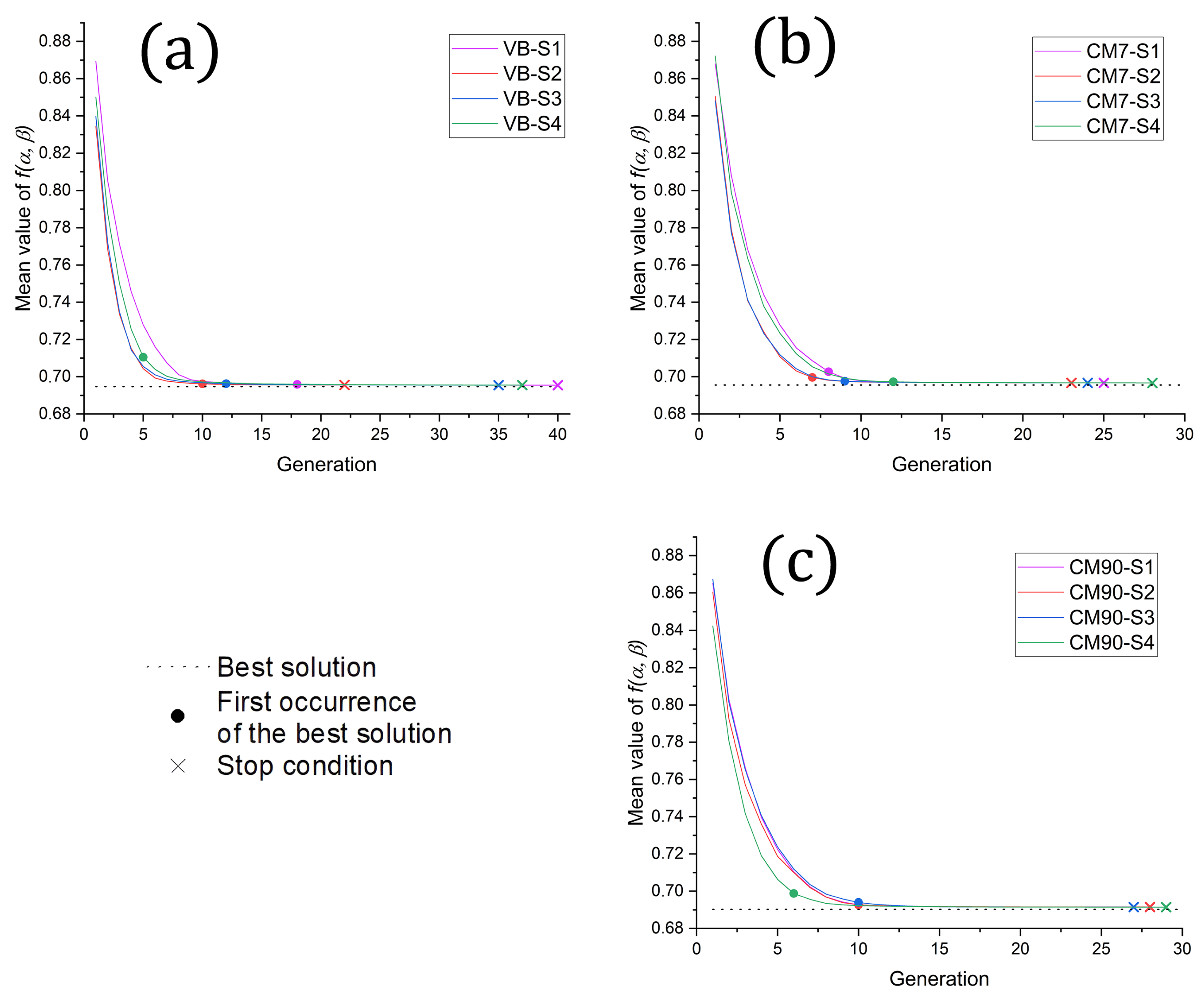
Figure 8 traces the population-mean objective function over generations for the three processing routes. All simulations converge to values below
, which corresponds to a stiffness increase of more than thirty percent relative to the quasi-isotropic lay-up.
The best sequences obtained are reported in
Table 4:
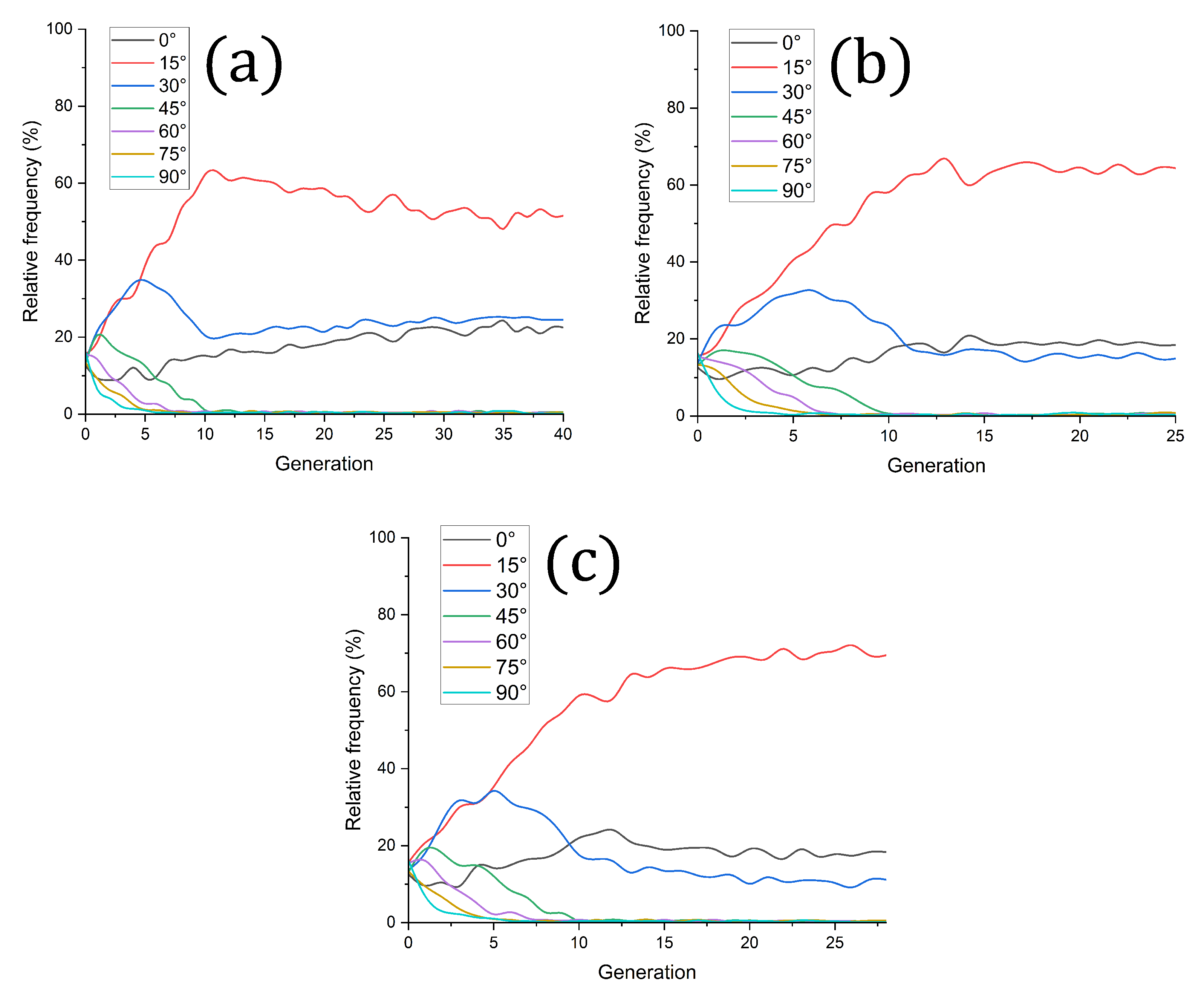
Figure 9a–c plot the evolution of angle frequency for one representative run per condition. In VB a mixture of 0°, 15° and 30° survives to the last generation; CM7 shifts weight toward 15°; CM90 collapses on a single 15° orientation. The trend mirrors the decrease in ply thickness with pressure: thinner plies in CM90 even out the moment arms about the neutral axis, so a uniform 15° stack offers the best compromise between bending and torsion. In VB the thicker plies and higher porosity benefit from a small fraction of 0° layers to improve bending rigidity.
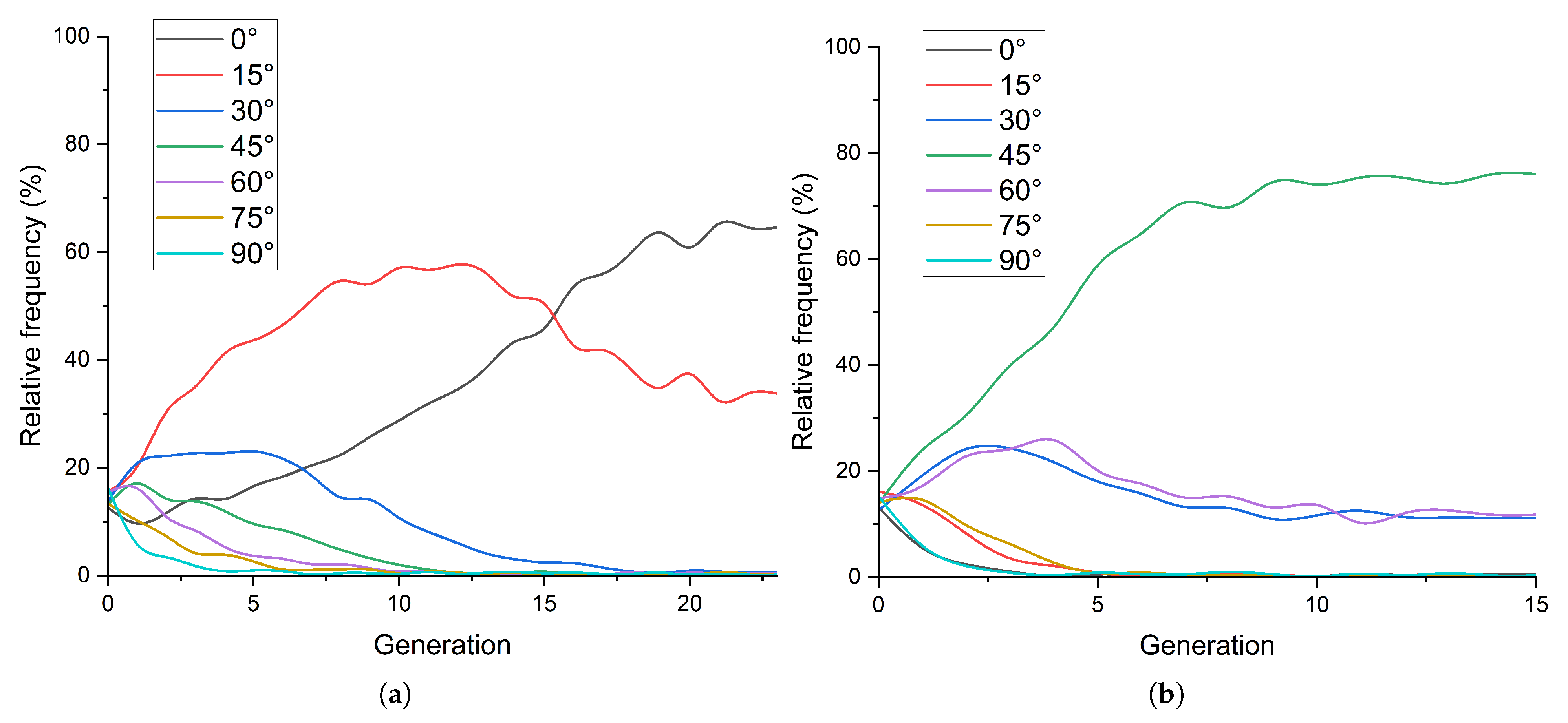
For reference the GA was also run on VB properties with the objective restricted to bending or torsion only. Pure bending converged to a full 0° lay-up, while pure torsion selected 45° throughout.
Figure 10 shows the corresponding angle-frequency histories. The combined-loading solution sits between these extremes, confirming that the mixed objective steers the laminate toward a lamination sequence able to balance the performance in the two loading cases.
Overall, the GA reduces the combined bending-torsion deflection by more than 30% relative to the quasi-isotropic baseline across all processing routes. Low-angle plies dominate every optimum, with the balance among 0°, 15° and 30° shifting as ply thickness and stiffness vary with consolidation pressure. Convergence is achieved in fewer than forty generations with the chosen mesh and population size.
3.4. Validation of Bending Stiffness
Three tubular specimens (T1, T2, and T3) were manufactured via vacuum-bagging and tested under three-point bending (3PB) to validate the finite-element model’s flexural predictions. Although this small-scale campaign already reproduces the numerical response and suggests the approach is feasible, additional tests will be required to build a comprehensive picture of the system behavior. Each tube employed the stacking sequence derived from the VB lay-up optimization, and the model’s force-displacement outputs were compared with experimental results in the small-deformation regime. The 3PB rig consisted of two 15 mm-diameter lower rollers spaced 180 mm apart and a 33.15 mm loading nose; tests were run on an Instron 1185R5800 under displacement control at 1 mm min
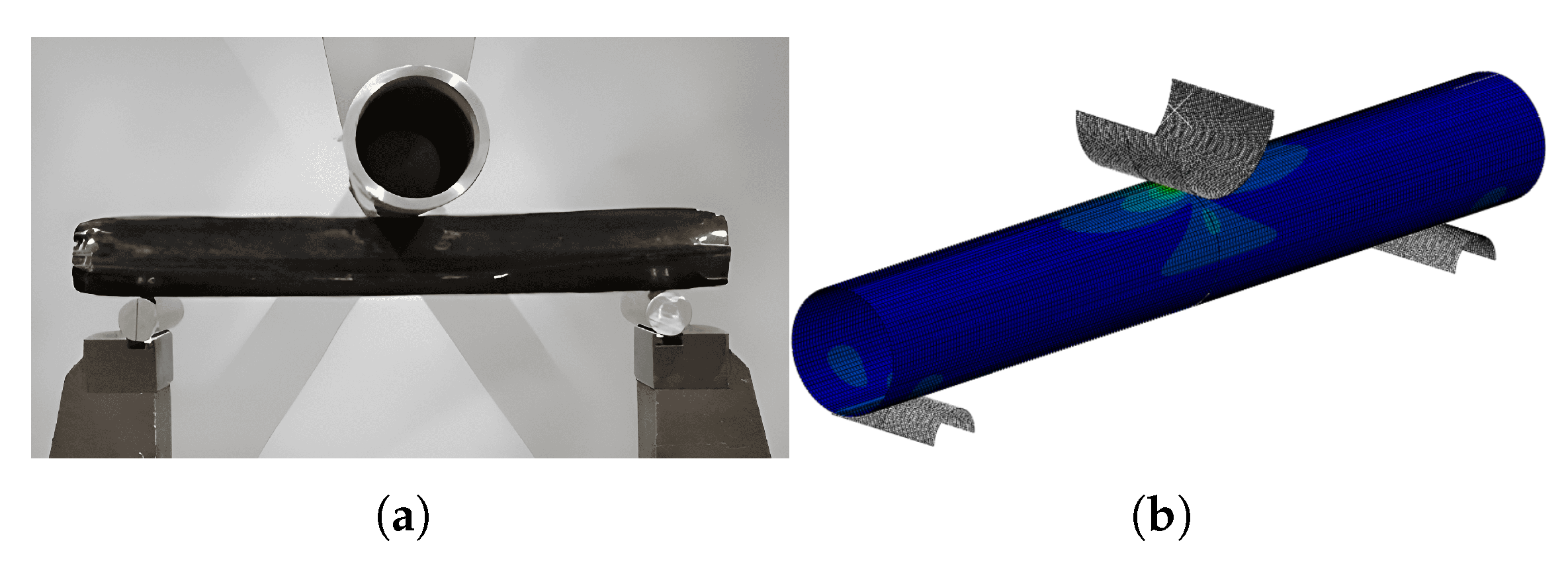
−1. The experimental setup and the corresponding numerical model in Abaqus are shown in
Figure 11a and
Figure 11b, respectively.
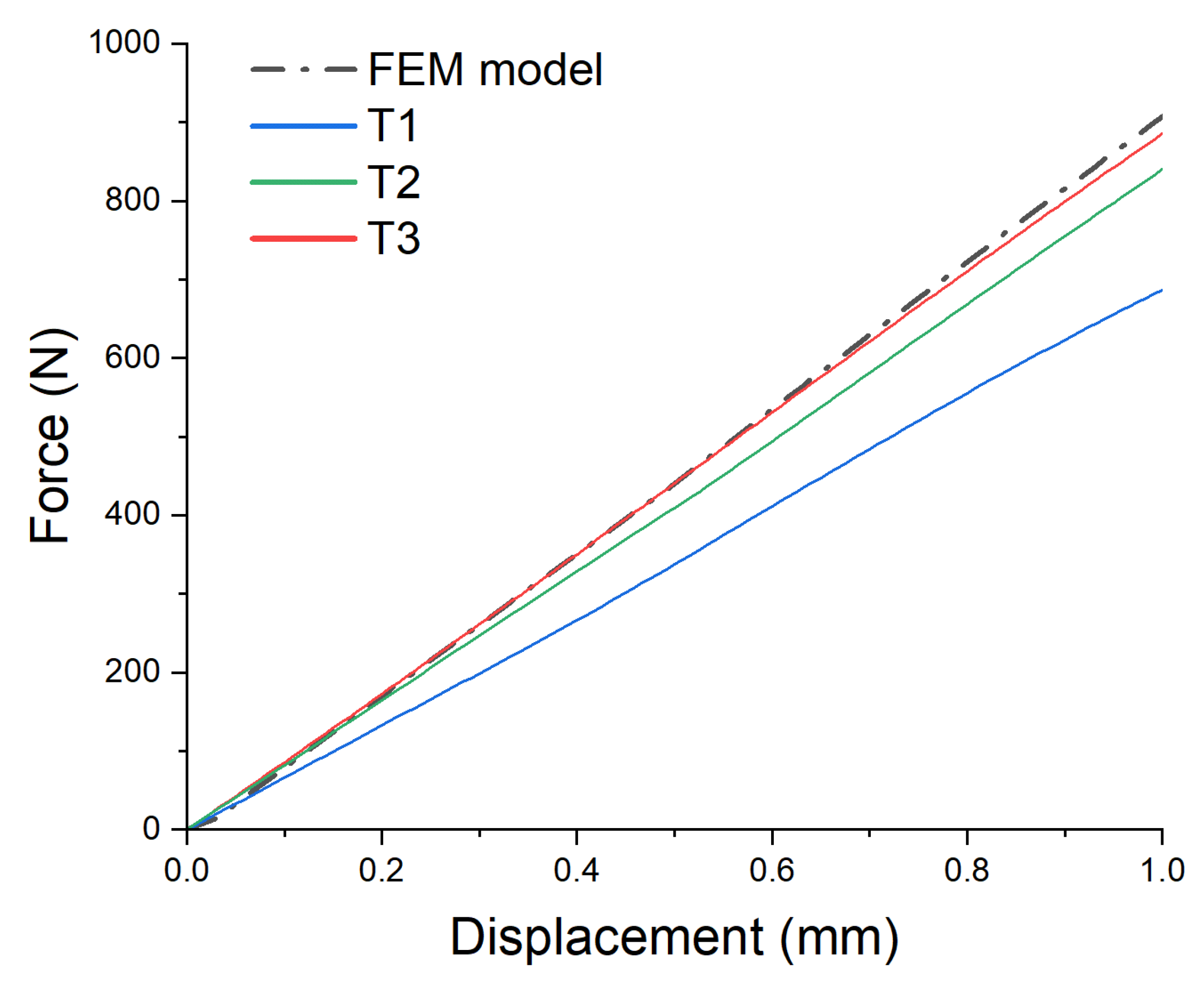
Figure 12 shows that finite-element predictions for T2 and T3 closely match the experimental curves up to approximately 1 mm displacement, confirming the model’s validity within the elastic range. In contrast, T1, the first specimen to be manufactured, deviates significantly from the expected behavior. The experimental results yield two main insights. First, the close match between the FEA and experimental stiffness of T2 and T3 supports the use of a CLT-derived stiffness matrix to model the flexural behavior of AFFT
™ structures—even with their inherently discontinuous fibers. Second, the poor performance of T1, attributed to manufacturing inconsistencies and higher porosity, underscores the sensitivity of AFFT
™ laminates to processing quality. Despite this sensitivity, the consistency between T2 and T3 suggests that AFFT-based composites can successfully achieve reliable performance through careful manufacturing.
As the finite-element model is linear elastic and does not capture indentation or damage mechanisms, comparisons are restricted to the first millimeter of cross-head travel, where the experiments remain within the elastic regime and therefore the comparison with the FE model is meaningful. Beyond this region, local indentation and progressive damage dominate, introducing nonlinearities not captured by the Finite Element model. Nonetheless, the agreement observed for T2 and T3 validates the finite-element approach for stiffness prediction within the elastic regime and confirms its effectiveness in guiding lay-up design for AFFT-based laminates.
4. Conclusions and Future Developments
This study demonstrated that Aligned Formable Fibre Technology (AFFT™) can efficiently repurpose reclaimed short carbon fibers into high-performance composites suitable for structural applications such as a bicycle top tube. By comparing three manufacturing methods (VB, CM7, and CM90), it was shown that increased compaction pressure reduces porosity and significantly improves the mechanical response of AFFT™ laminates. The application of Classical Laminate Theory (CLT) within a finite-element framework, supported by a genetic algorithm (GA) for lay-up optimization, enabled the design of tailored laminates with enhanced stiffness under combined bending and torsion. Tube-scale validation confirmed the model’s ability to predict the flexural behavior of AFFT™ composites in the small-deformation regime, despite the intrinsic discontinuities of the fiber architecture.
Looking ahead, improvements in manufacturing consistency, adoption of more realistic load profiles, and the integration of failure criteria into the finite-element model could further enhance the reliability of stacking sequence optimizations. Extending the GA to penalize failure-prone configurations would enable a more balanced trade-off between stiffness and damage resistance. Moreover, a more precise objective function can be employed, tailored on the specific final application, without affecting the consistency of the optimization pipeline. Additionally, future research might exploit closed-loop recycling by reclaiming end-of-life carbon fiber bicycle frames and reprocessing them via AFFT™, thereby contributing to enhanced sustainability. Through these refinements, AFFT-based composites can move closer to a truly circular life cycle while keeping mechanical properties at a level which is comparable to continuous-fiber systems.