Article

Lightweight and Sustainable Steering Knuckle via Topology Optimization and Rapid Investment Casting

1
Department of Enterprise Engineering, University of Rome “Tor Vergata”, Via del Politecnico 1, 00133 Rome, Italy
2
Department of Economics, Engineering, Society, and Business Organization, University of Tuscia, Via del Paradiso 47, 01100 Viterbo, Italy
*
Author to whom correspondence should be addressed.
J. Manuf. Mater. Process. 2025, 9(8), 252; https://doi.org/10.3390/jmmp9080252
Submission received: 11 June 2025 / Revised: 8 July 2025 / Accepted: 21 July 2025 / Published: 24 July 2025

Abstract

Considering the importance of the automotive industry, reducing the environmental impact of automotive component manufacturing is crucial. Additionally, lightening of the latter promotes a reduction in fuel consumption throughout the vehicle’s life cycle, limiting emissions. This study presents a comprehensive approach to optimizing and manufacturing a MacPherson steering knuckle using topology optimization (TO), additive manufacturing, and rapid investment casting (RIC). Static structural simulations confirmed the mechanical integrity of the optimized design, with stress and strain values remaining within the elastic limits of the SG A536 iron alloy. The TO process achieved a 30% reduction in mass, resulting in lower material use and production costs. Additive manufacturing of optimized geometry reduced resin consumption by 27% and printing time by 9%. RIC simulations validated efficient mold filling and solidification, with porosity confined to removable riser regions. Life cycle assessment (LCA) demonstrated a 27% reduction in manufacturing environmental impact and a 31% decrease throughout the component life cycle, largely due to vehicle lightweighting. The findings highlight the potential of integrated TO and advanced manufacturing techniques to produce structurally efficient and environmentally sustainable automotive components. This workflow offers promising implications for broader industrial applications that aim to balance mechanical performance with ecological responsibility.

1. Introduction

The steering knuckle is a critical component of a vehicle’s suspension system, serving as the main link between the wheel hub and the suspension. It transfers forces from the tires to the suspension, making it subject to high and varying loads [1,2]. As a result, its design must prioritize durability and a high safety factor. Additionally, the knuckle should be engineered for robustness, with adequate fatigue life, optimal material selection, and minimized weight, without compromising the overall mechanical performance.
Its geometry changes depending on the specifications of the steering system and the suspension system, including the spatial coordinates of other parts, assembly constraints, and joints [3,
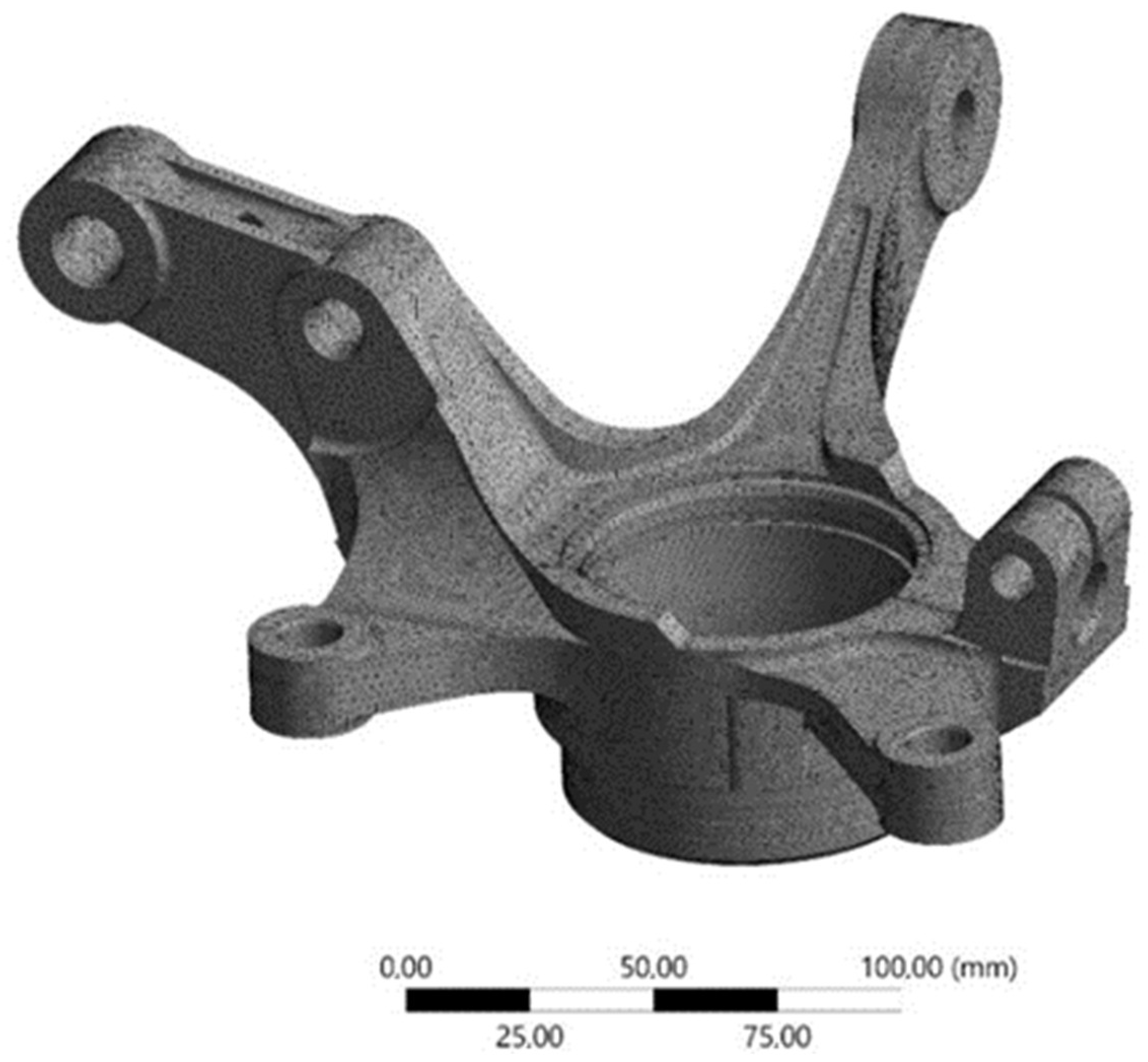
4]. In particular, the steering knuckle of the MacPherson suspension system [5,6], used on several commercial vehicles (i.e., Fiat Siena, Toyota Corolla, Dacia Logan), was considered and is shown in Figure 1.
However, depending on the classification of the car, different materials (such as cast iron, forged iron, aluminum, and composite materials) are used to manufacture the car’s steering knuckle [3,7].
Among the different manufacturing processes available to create parts with complex geometries with medium-high production volumes, one of the best options is investment casting (IC). IC is one of the oldest manufacturing techniques, involving the pouring of molten metal into a mold where it solidifies into a desired shape [8]. However, a fundamental drawback of the process is the formation of shrinkage cavities, which result from the volumetric contraction that occurs during the liquid-to-solid phase transformation [9,10,11]. A common approach to mitigate this issue involves incorporating excess material in the form of risers, dowels, sprues, and cores [12,13]. As a result, the typical material recovery rate in casting, i.e., the ratio of the final product weight to the total molten metal used, is approximately 70%, with around 30% of material wasted. Moreover, additional processing is required to remove this surplus material, leading to increased consumption of both material and energy. With the rise of additive manufacturing (AM) technologies in the last decade, casting processes have benefited due to the spread of rapid tooling (RT). RT is intended for when AM technologies are used to directly manufacture tools or tooling inserts for molding or for any other technology that requires a specific shape to produce a part [14,15]. Among the various manufacturing processes supported by rapid tooling (RT)—such as injection molding and die casting—investment casting (IC) has been particularly enhanced by the use of additive manufacturing (AM) to produce meltable patterns. This technique, commonly referred to as rapid investment casting (RIC), allows for the fabrication of complex-shaped sacrificial models made of foundry resin, which are later removed to create the mold cavity [16,17]. RIC has proven to be especially effective in applications involving metal foams [16], reticular or lattice structures [17,18], and is increasingly adopted in the production of functional parts for the automotive [19] and aerospace sectors [18,20,21,22,23,24].
In the automotive industry, weight is always an essential criterion while designing any vehicle component. One of the modern methodologies to reduce the weight without compromising the intended performance of the part is the topological optimization (TO) [21,22]. The environmental benefits of topology optimization (TO) have been widely explored in the recent literature, particularly in relation to material savings, weight reduction, and associated improvements in energy efficiency during both production and use phases. Several studies have demonstrated how TO can significantly reduce the environmental footprint of mechanical components by minimizing mass while maintaining or enhancing structural performance [23,24,25].
These works provide a valuable foundation for the current study, which aims to expand on this approach by integrating TO with process-specific simulation and life cycle assessment. TO has its application in the automobile sector for lightweight components and fuel efficiency. For instance, Bajpai et al. [26] carried out a topology optimization of the steering knuckle of a formula SAE with consideration of boundary conditions and loading conditions acting on the component. After optimization by designing and analysis using the FEA solver, a 40.87% reduction of weight was obtained without compromising the initial performance of the steering knuckle. Zach et al. [27] performed a topology optimization on a formula SAE steering knuckle and reduced the original mass of the part to only 45.2% (compared for the same materials) and 29.28% of the machined variant from AA 7075. In addition, the safety coefficient is increased by 3.06% compared to the unoptimized AA 7075 and the optimized Ti-6Al-4V design variants.
Due to the different kinds of geometries, manufacturing methodologies, and possibilities of TO, the steering knuckle is a suitable component for a life cycle assessment (LCA) analysis. Current European environmental and raw materials policies emphasize the importance of sustainability and recyclability in tackling urgent ecological and resource-related challenges.
In the scientific literature, LCA has been extensively applied to assess the sustainability of manufacturing technologies across a wide range of industrial sectors. Recent studies have shown that LCA can offer valuable insights for developing lower-impact processes and guiding decision-making in the adoption of new methodologies at the industrial level [28].
For instance, Venettacci et al. [20] used LCA to compare the environmental impacts of surface finishing processes in the aerospace sector, demonstrating a 45% reduction in overall impacts when innovative technologies were adopted over traditional methods. Similarly, Müller-Carneiro et al. [29] highlighted the significance of Ex-Ante LCA in evaluating emerging technologies during the research and development phase, particularly in addressing challenges related to data uncertainty and the modeling of large-scale production. Collectively, these studies underscore the pivotal role of LCA in assessing the sustainability of technological innovations, offering a methodological foundation for studies such as the present one.
This work aims to perform a TO of a SG Iron A536 65-45-12 steering knuckle manufactured by RIC to obtain a component that guarantees similar mechanical responses in terms of displacement under load, Von-Mises’s stress, and safety factors with a lower weight and volume of material.
Moreover, an LCA analysis is performed as a comparison between the actual and the optimized geometry to understand the improvements in terms of environmental impact using the Impact 2002+ methodology and indicators. In a context where the sustainability of manufacturing processes is becoming of primary importance due to reasons of legislation compliance and competitiveness, the reduction of the analyzed indicators, in particular those relating to human health, ecosystem quality, climate change, and resources, is totally in line with the objectives of different industrially relevant regulations and standards (i.e., ISO 14001, REACH, and European voluntary declarations such as EMAS) [30].
The outcomes of this study can guide different steering knuckle manufacturers to use topologically optimized components regardless of the geometry and have a key role in evaluating the best option, jointly considering technical and environmental drivers. This study aims to bridge the gap between topology optimization and sustainable manufacturing by integrating a complete design-to-casting workflow for a structural automotive component. Specifically, it combines topology optimization (TO), rapid investment casting (RIC), and life cycle assessment (LCA) applied to a steering knuckle. This approach enables a comprehensive evaluation of structural performance, manufacturability, and environmental impact within a unified framework—an aspect seldom explored in the current literature.

2. Materials and Methods

2.1. Loading Conditions Choice

The steering knuckle is a core connection component between many antivehicle parts. Its function is to provide a connection between the suspension system, the brake caliper, the tie rod, and the lower control arm. The calculations of the loading conditions acting on the steering knuckle were performed by knowing the gross mass of the vehicle of 1313 kg (equivalent to the mass of a Toyota Corolla with a MacPharson suspension system). As a simplifying hypothesis, a mass distribution of 50:50 on the front and rear axles was considered, with the mass equally shared among the wheels, as noted in references [31,32]. The mass distribution per wheel can be calculated as the total mass of the vehicle divided by four, giving a total of 328.25 kg for each wheel.
The forces acting on the knuckle were estimated using empirical expressions based on gravitational acceleration and mass distribution (m), as summarized in Table 1. These expressions include multiplicative empirical factors (e.g., 1.5, 3.0, 1.0) commonly adopted in the literature to account for safety margins and dynamic load amplifications under various operating conditions.
By knowing the different forces on the knuckle hub along three axes, the resultant force on the hub can be calculated as follows:
F x 2 + F y 2 + F z 2
where F x 2 is the force acting on knuckle hub on the X-axis, F y 2 is the force acting on knuckle hub on the Y-axis, and F z 2 is the force acting on knuckle hub on the Z-axis.

2.2. Static Structural Analysis

Structural analysis of the steering knuckle was conducted using the software Ansys v.2023R2. The material properties of the SG iron used for the simulation are shown in Table 2.
The finite element mesh was generated using Ansys 2023 R2, adopting unstructured tetrahedral elements. This approach was selected to effectively capture the intricate and organic shapes derived from topology optimization. Mesh refinement was automatically applied in high-stress regions using adaptive control criteria to ensure numerical accuracy without excessive computational cost.
A multi-zone meshing strategy was not used, as the irregular geometry resulting from TO is more efficiently handled with tetrahedral elements, which offer greater flexibility in capturing complex curvatures and varying thicknesses. The resulting model and mesh properties are shown in Table 3, while the visual of the mesh is shown in Figure 2.
For the static structural analysis, boundary conditions were defined by using the calculated values of forces indicated in Table 1. Force lines of action are derived based on the connectivity of the steering knuckle to the other components and functions. Constraints and load distribution on the model are shown in Figure 3.

2.3. Topological Optimization

Topological optimization (TO) is a structural optimization technique that optimizes the material layout within the design domain under applied loading and bounding conditions without compromising its functionality. The density-based topology optimization was performed on the steering knuckle to reduce the weight of the component without affecting its structural integrity. Based on the stress levels obtained through the static structural analysis, the low-stress regions were identified, and material removal was performed in the zones that present the highest safety factor (i.e., areas where the transferred load is low). Compliance minimization was adopted as the main objective function in the topology optimization process. This choice was motivated by the fact that compliance is inversely related to global stiffness, which is a fundamental requirement for the performance and safety of structural components such as steering knuckles. Although this objective does not directly account for other mechanical aspects such as fatigue life or vibrational behavior, it offers a computationally efficient and robust starting point for lightweight design under static loading conditions. Alternative optimization targets—such as strain energy minimization, modal performance enhancement, or fatigue resistance—are acknowledged as relevant and will be considered in future extensions of this work. To understand material removal in low-stress regions, different algorithms have been implemented. One of the most used algorithms is the solid isotropic material with penalization (SIMP), which represents a density-based topology optimization (DBTO) approach and is commonly used for solving material distribution problems. DBTO includes multiple design variables, constraints, and objectives that allow an effective material removal in low-stress regions. A typical TO problem initially defines the loads and constraints within the design domain [33]; then, the domain is discretized into several finite elements and nodes. In the SIMP approach, the element density within the design domain is optimized in terms of 0 and 1, where 0 represents the void region and 1 represents the solid region. The element density can be mathematically formulated as follows:
ρ i =   f x = 1 ,    Ω i     Ω m a t 0 ,    Ω i     Ω / Ω m a t
Where ρi denotes the element density, Ωi represents the design domain of i-th element, Ωmat denotes the structural topology, and Ω denotes the design domain. The mathematical formulation for the minimal compliance problem in the finite element form can be written as follows:
f i n d ρ = ρ 1 ,   ρ 2 , ,   ρ m   R m
min ρ   R m c = U T F
s . t .    K   ρ   U = F
g 0
0 ρ e 1 ,   e = 1 ,   ,   N e
where findρ represents the density variable composed of element-wise element density (ρe), m represents the number of design variables, Rm represents a set of m real numbers, c represents the structural compliance which acts as the objective function, K represents the global stiffness matrix, g represents the volume constraint, and F represents the external load vector [34].
The TO process was performed using the software Ansys. The exclusion regions (i.e., the zones retained after the TO) were considered the zones where the boundary conditions were applied, while the rest of the domain was selected as the design region. The parameters considered for implementing the SIMP algorithm are listed in Table 4. In the present study, the topology optimization was performed using compliance minimization under a prescribed volume constraint. No additional manufacturing constraints—such as overhang angle, draw direction, or symmetry—were applied during the optimization stage. This choice was due to limitations in the Ansys solver version used, which did not support advanced design for additive manufacturing (DfAM) constraints within the topology optimization module.
Nevertheless, manufacturing feasibility was addressed in the post-processing phase by analyzing printability and optimizing the building orientation using Photon Workshop to minimize support structures.
Future developments of this work will aim to integrate manufacturability constraints directly into the optimization loop to generate production-ready geometries with reduced need for post-adjustment.

2.4. Rapid Investment Casting Design and Simulation Parameters

After the static structural simulations and the TO of the component, a slicing of both components was performed using the software Anycubic Photon Workshop version 3.6.2 to simulate the quantity of castable resin used for both foundry models and the relative supports as well as the 3D printing time since it is related directly to the overall costs sustained by knowing the costs for the electricity and the resin. To optimize the steering knuckle orientation on the printing platform, the software’s orientation optimizer was used, which reduces the supports and printing times to a minimum without affecting the printing quality. The parameters chosen for the model slicing are shown in Table 5. In particular, the choice of a castable resin enables the creation of models with accurate features, almost no shrinkage, and easier to burn in the oven.
After obtaining the foundry models used for the RIC process, the gating systems were designed. The gating system is responsible for sustaining the whole pattern and mold, and its design alteration can reduce metal consumption per casting, which may affect industrial production economically [35]. The inlet gate, casting channels, and risers were designed for both analyzed cases using the CAD software Autodesk Fusion version 2603.1.15. After designing the overall systems, casting simulations were performed using the software Altair Inspire Cast version 2021.2.
The filling time was chosen according to the equation derived from [36]:
T = 2 G
where G is the mass of the optimized steering knuckle.
The mean volumetric flow rate could be calculated as follows:
Q m = V T
where V is the volume of the optimized component, and T is the filling time.
Since the metal flows in the mold under the effect of gravity, it is possible to estimate the initial speed of the casting with Torricelli’s law:
v f = 0.65 2 g H
S i = Q m v f
where vf is the feeding velocity, g is the gravity, H is the height of the column of molten metal over the model, and Si represents the cross-sectional area of the inlet gate, calculated based on the desired flow rate and feeding velocity. The coefficient 0.65 is used to consider the effect of the friction, pressure drops, and viscosity.

2.5. Life Cycle Assessment Analysis

Life cycle assessment (LCA) analysis has been performed to evaluate the environmental impact of the standard steering knuckle geometry and its TO counterpart manufactured by RIC. Analysis was carried out according to the standard procedure UNI EN ISO 14040 standard [37], using SimaPro 8.0. for the implementation of the LCA model.
The boundary conditions and the two goals were defined as follows:
  • LCA considers the production process of four steering knuckles with two different geometries (cradle-to-gate approach).
  • LCA considers the production process of four steering knuckles with two different geometries (standard and TO) and their life cycle mounted in a small-capacity commercial vehicle covering 200,000 km in its lifetime (cradle-to-grave approach).
The knuckles were produced using RIC as functional units with a cradle-to-gate approach. The steps included in the manufacturing process were those reported in Figure 4, involving the electricity and the resin used for printing the TO 3D model, the isopropanol and electricity used for the washing, UV curing of the optimized model, the materials and energy used for the preparation of the plaster molds, the amount of steel melt and electricity to power the oven, and finally the water and electricity for subsequent material post-processing. In the analysis, the shrinkage of the iron alloy during the casting process was considered and assumed to be constant for both processes, equal to 2%.
Inventory was conducted using data on raw materials and energy consumption measured or provided by the equipment manufacturer (casting step). The analysis was carried out using EcoInvent 3.0 and the PEF database (European Commission database) considering extraction and transportation of raw materials.
The following are the hypotheses proposed for the investigation:
  • The power consumption of the 3D printing of the model was measured with a power analyzer.
  • The power consumption of the washing and curing step (Wash and Cure Max, Anycubic) was measured with a power analyzer.
  • The power consumption of the mold preparation (MRC/B, Italimpianti Orafi s.p.a., Badia Al Pino, Italy) was measured with a clamp meter.
  • The electricity needed for casting (IGBT-25, Shanghai FORTUNE ELECTRIC Co., Shangai, China) was provided by the equipment manufacturer.
  • The post-processing consisted in the removal of the mold with a water pressure washer (Clean Power 1200, Marwis 24, Zielona Góra, Poland), after the removal of the mold risers and inlets were removed with a CNC tools. The power consumption was measured with a clamp meter.
  • The wear of the instruments used was considered to be negligible because the lifetime of the instruments far exceeds the time required to produce the specimens.
The method chosen to calculate the environmental impact was the Impact 2002+. This methodology combines midpoint and endpoint approaches and takes into consideration 13 different indicators at the intermediate level, as well as grouping them into four damage categories, assigning them a single score through a procedure of normalization and weighting [38]. These four damage categories are human health, ecosystems, climate change, and resources; likewise, it is possible to see the impact, in terms of the score on the functional unit (Pt), of each phase and process.

3. Results and Discussion

3.1. Topology Optimization

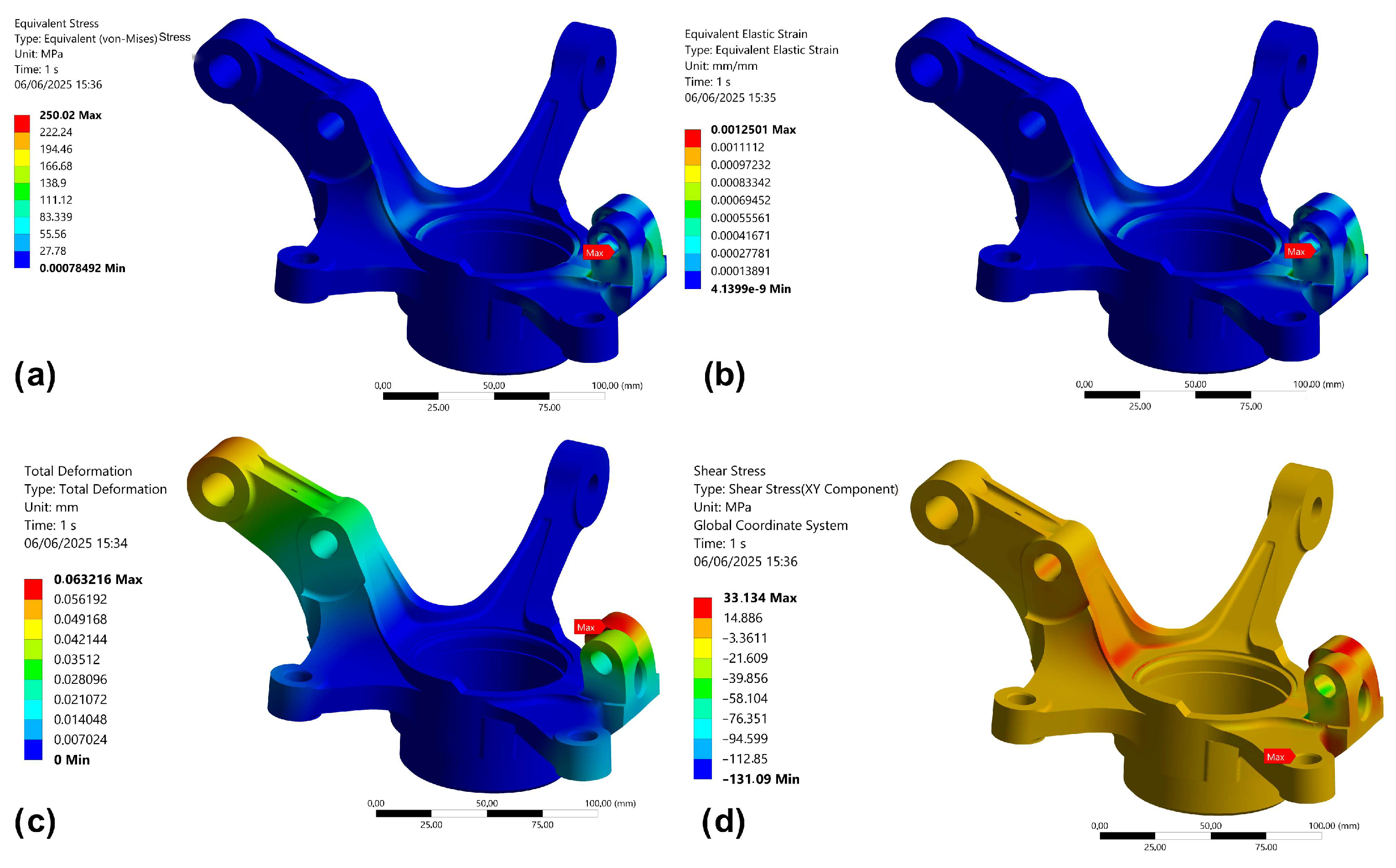
The results of the static structural simulation are shown in Figure 5. The most stressed region is the region connected with the lower control arm, where we have all the maximum values from the simulation. In particular, the maximum Von Mises stress of 250 MPa is lower than the yield strength of the SG A536 iron alloy used, which is 310 MPa, enabling a safety factor of 1.25 for the load case considered. Also, the results in terms of equivalent elastic strain show that the max values obtained are below the elastic limit of the material (0.002), suggesting there is no plastic deformation involved. Moreover, total deformation reaches a peak of 0.06 mm, and shear stress reaches a peak of 33.13 MPa, which is very compliant with the design limits according to the material used and the given boundary conditions.
Once assured of the goodness of the results obtained from the static analysis, the TO was carried out using the structural optimization tool of Ansys Workbench using the parameters discussed in the previous section in 
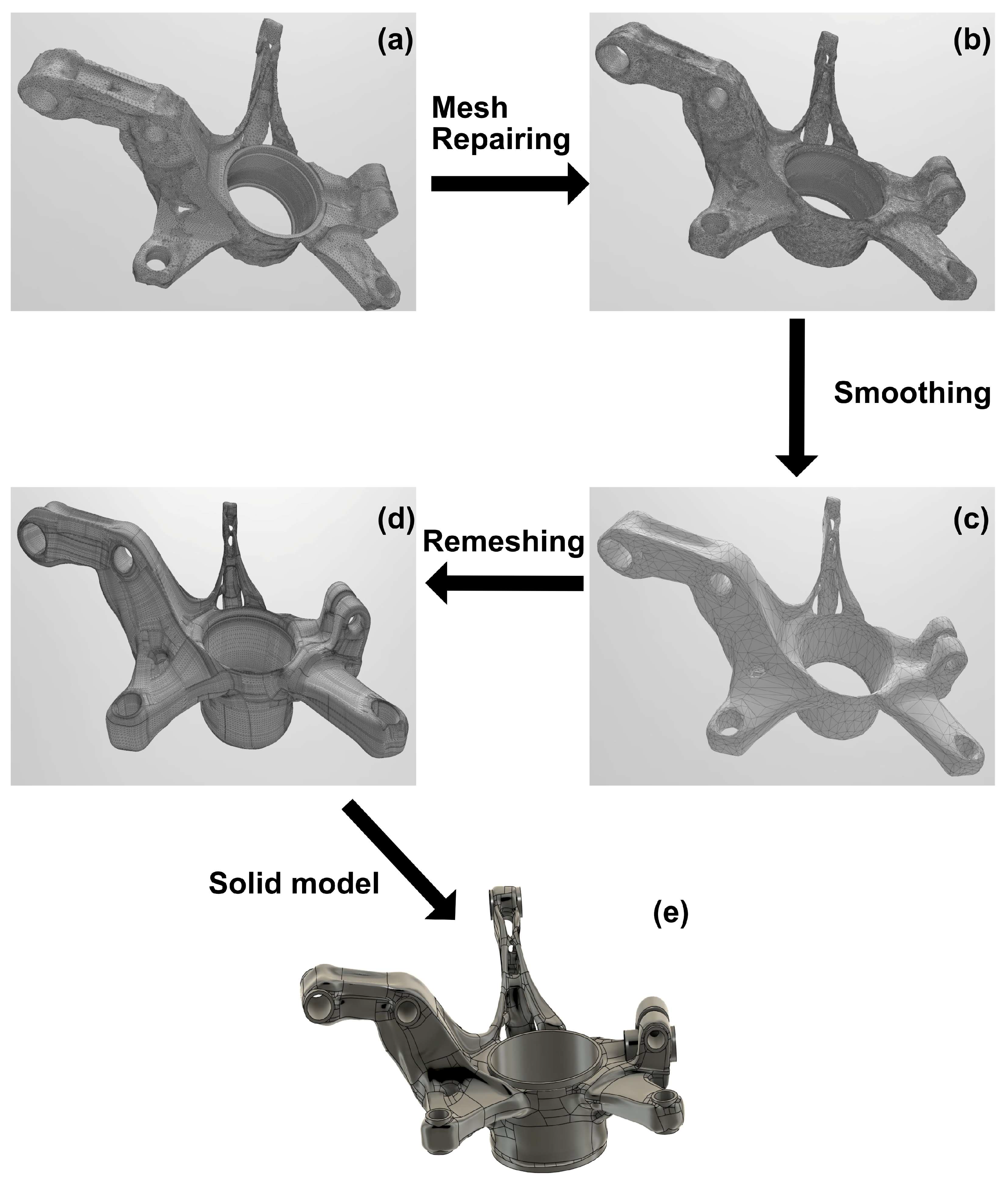
Table 3. The output of the optimization is an STL file of the new model, shown in Figure 6a, and has some parts of the triangular mesh that were not merged with the others. Thus, using the software Autodesk Fusion, mesh repairing was performed (shown in Figure 6b) in order to eliminate the missing elements and merge the elements closer to a certain gap of 0.1 mm. The new closed surface was processed to obtain a part with a degree of smoothness that can avoid possible stress concentrations under load. Additionally, support zones had to be recreated to ensure the connection of the optimized component with the other components of the assembly. The surface was then reshaped as a surface body and subsequently converted into a solid body for the subsequent testing and process steps (Figure 6). The addition of material to make the connection zones resulted in an increase in mass of about 10%.
In Table 6 and Figure 7, all the model and mesh properties of the topologically optimized steering knuckle are shown. Compared to the unoptimized geometry, there is a volume and mass reduction of 30%, which would reduce the overall mass of the vehicle by 3.2 kg since the component is installed on each wheel. Although the topology-optimized geometry presents a significant reduction in mass, certain features—such as the rear arm of the knuckle—exhibit slender cross-sections that may pose manufacturability challenges when applying investment casting.
To address this, a post-processing step was performed after the topology optimization phase, during which the geometry was slightly modified to improve castability. This included the elimination of sharp edges, reinforcement of critical thin regions, and verification of minimum wall thicknesses.
These refinements were based on foundry design guidelines and aimed to ensure compatibility with mold filling behavior and ceramic shell stability. While not explicitly illustrated in this study, these adaptations were essential to align the optimized design with the constraints of rapid investment casting.
To validate the optimized design, another static structural simulation was performed with the same boundary conditions as the previous one and its results are shown in Figure 8. The most stressed region is again the one connected with the lower control arm. The maximum Von Mises stress of 280 MPa is still lower than the yield strength of the used alloy, enabling a safety factor of 1.11 for the load case considered, which is lower than the previous one since part of material was removed. Moreover, the results in terms of equivalent elastic strain show that the obtained max values of 0.0018 are below the elastic limit of the material (0.002), suggesting that even in this case there is no plastic deformation involved. Finally, total deformation reaches a peak of 0.05 mm, and shear stress reaches a peak of 27.49 MPa, which is in line with the design limits.
A comparison of the results of structural analysis on both configurations is shown in Table 7.

3.2. 3D Printing of the Knuckles

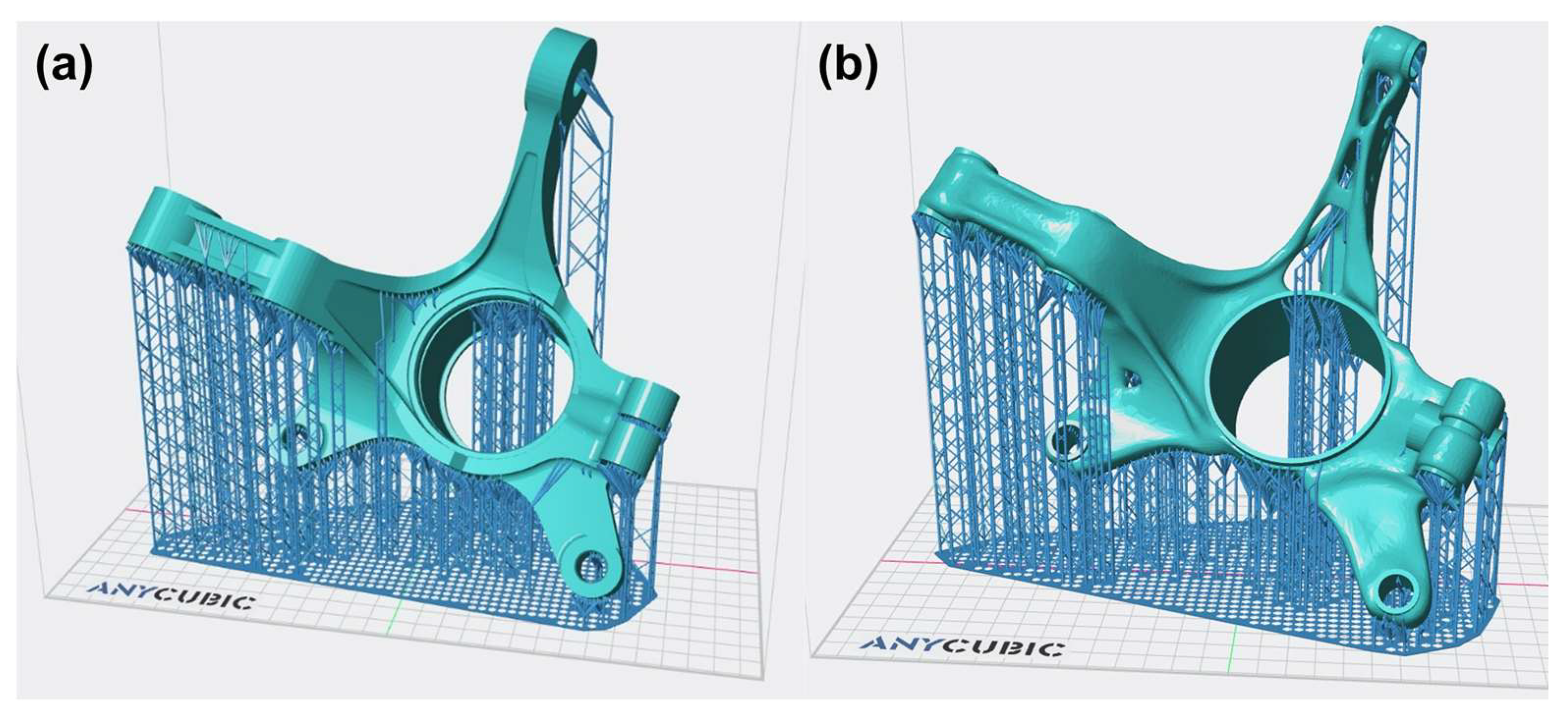
After the validation phase, an evaluation of the printing time and resin usage for the obtained models was performed using the software Anycubic Photon Workshop. The supporting structures and the orientation were optimized using the software tool and shown in Figure 9.
In particular, the used resin volume for the unoptimized model is 497.27 mL, compared to the 361.89 mL for the TO model, obtaining a material saving of about 27%. Since the cost of the used castable resin is around 150 EUR/L, the saving of the material usage alone is 20 EUR using the optimized model (74.50 EUR vs. 54.28 EUR). Moreover, there is also a reduction of the printing time, which goes down from 575 min to 525 min, also leading savings in terms of electricity used for the process. The UV curing process was supposed to be under the same conditions in the Anycubic Wash and Cure Max, using a temperature of 60 °C for the polymerization for 30 min.

3.3. Rapid Investment Casting Simulation

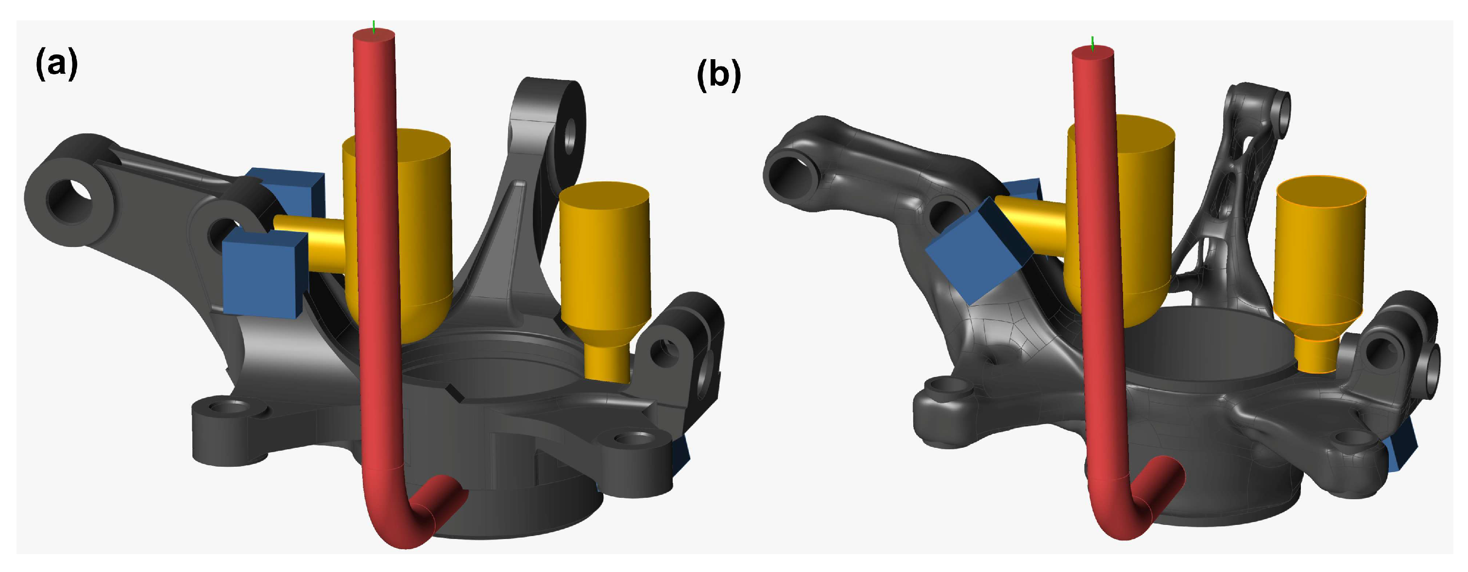
Subsequently, the gating system was designed using the Autodesk Fusion software for both configurations, considering the different thermal modules of the zones and the corresponding cylindrical matrices increased by 30% concerning the thermal module value of the connecting zones. Two different risers were identified and added, with the dimensions, volumes, and weights described in Table 8.
For the inlet gate design, according to the equations defined in sub-paragraph 2.4, the filling speed was equally imposed at 2 m/s. The inlet gate section Sa is 706.5 mm2 (D = 30.0 mm) for the initial geometry, while it is 637.5 mm2 for the TO model (D = 28.5 mm). In addition, copper chillers were added in both configurations in the area below riser number 1, and near the neck of number 2, to promote directional solidification in the most critical zones and bring that part of the component within the radius of influence of the risers. The overall gating system for both configurations is shown in Figure 10.
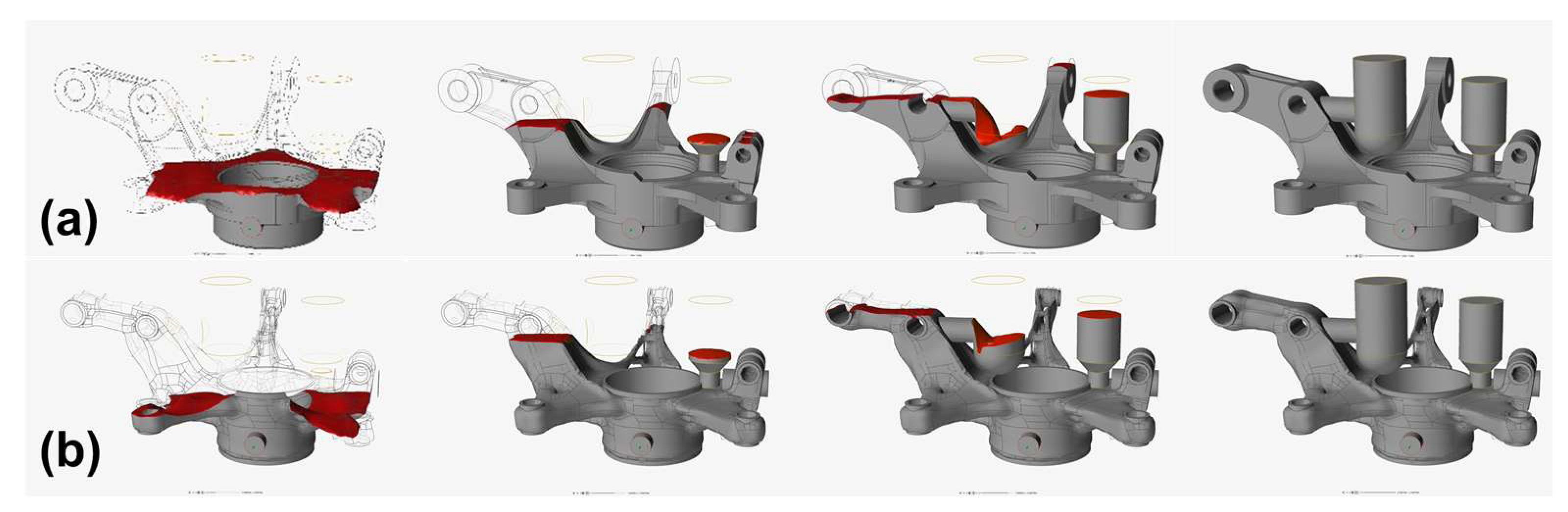
Successively, the RIC simulation was performed with the software Altair Inspire Cast, using the gating systems, models, and filling speed previously defined and a casting temperature of 1300 °C in accordance with material properties. Figure 11 shows the filling of both models at different percentages. In particular, the filling time it takes for the molten metal front to fill the entire model and risers is 3.06 s for the MacPherson steering knuckle and 2.37 s for the TO knuckle model. Both calculated times are in the ideal filling time range (0.5–5 s) for components with a mass higher than 1 kg produced with this process [36], since higher times would increase the risks of cold joints. The different filling time obtained depends on the smaller amount of molten metal required to fill the cavity, considering the same imposed filling velocity (2 m/s), even if the inlet section for the second case slightly decreases (thus, the volumetric flow rate).
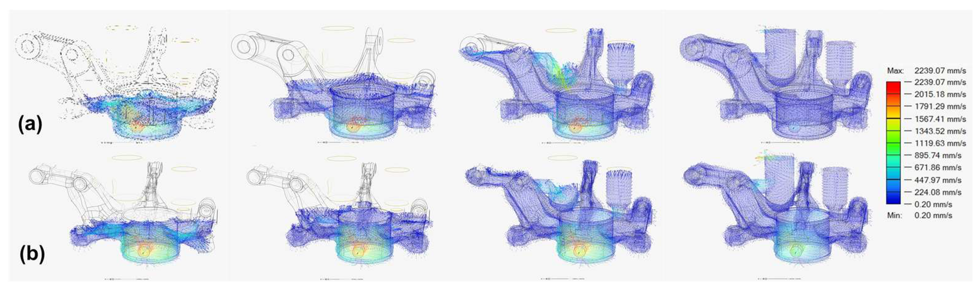
The velocity vectors at different filling percentages for both models are shown in Figure 12. It can be noticed that, for the two cases considered, the maximum filling speed over time is always in correspondence of the inlet gate. However, inside the cavity, the velocity is between 0.5 and 2 m/s, which is the ideal filling velocity range for a RIC process to avoid turbulences, gaseous inclusions, and improve the overall surface quality [36,39].
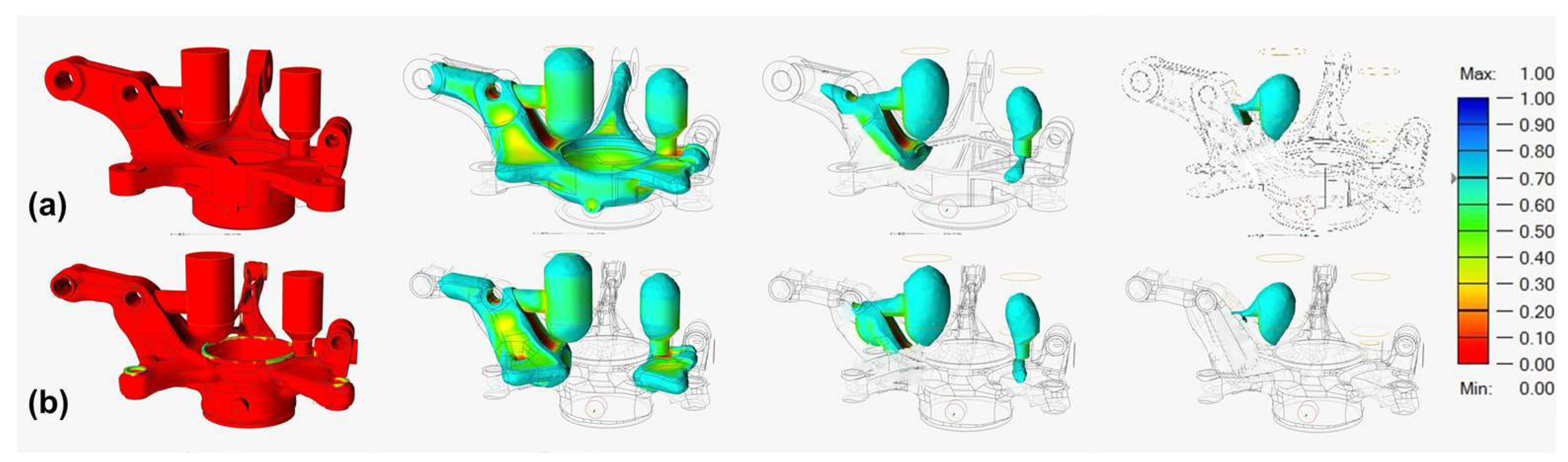
After the filling phase, computed solidification times for both models are 1370 s for the initial one and 1250 s for the topologically optimized. Figure 13 shows the analysis of the solid fraction at different times. It can be noticed that even in the initial seconds, the TO steering knuckle starts to solidify in the thin-walled zones (2 mm), compared to the unoptimized counterpart. Particular attention was paid to the castability of geometrically critical regions, such as the rear arm of the knuckle. Minor geometric refinements were introduced post-optimization to avoid shell failure and misruns during the filling process. Moreover, going forward with the solidification of both models, it is notable that the last part of the casting to solidify is in the risers, causing them to be able to absorb any shrinkage cones or cavities.
Figure 14 shows the largest porosities inside the model at the end of the solidification phase (90%). In both cases, the largest porosities are inside the designed risers, which means that the observed ones do not affect the structural strength and surface finish of both models produced. It can be noted that the porosities in the optimized model are greater, even though they are contained in the risers that will later be removed during post-processing and are therefore not influential.

3.4. Life Cycle Assessment

Once the goodness of the systems designed for manufacturing both components was assessed, a life cycle assessment (LCA) analysis was performed to evaluate the advantages in terms of environmental impact of the optimized component. The LCA analysis was performed by comparing the two RIC scenarios for the standard steering knuckle and the TO variant. The comparison was conducted both on the manufacturing processes and the life cycle of a full set of knuckles (four specimens) considering the environmental impacts calculated using the IMPACT 2002+ method, which evaluates four main categories of damage: human health, ecosystem quality, climate change, and resources.
In Table 9, the percentage of environmental impact for the rapid investment casting sub-processes of both components is shown. The casting process is dominant in terms of energy consumption in both scenarios, accounting for over 60% of the total. However, the environmental impact of the sub-process is significantly lower for the TO scenario because of a reduction in the needed casting metal. The percentage differences between the energy used for manufacturing the two components are marginal overall, with a slight decrease in the total energy consumption associated with 3D printing and casting in the optimized component due to the volume reduction. An increase is observed in “curing and cleaning” (+1.17%), while the environmental impact of the sub-process is perfectly comparable. All the observed variations for the model and 3D printing, mold preparation, casting, and post-processing can be attributed to the reduction of the materials involved in those processes (resin, plaster, and iron alloy), meanwhile the higher percentage impact of the curing and cleaning process might be attributed to the higher water and acetone consumption due to the complexity of the geometry. Although these variations are small in percentage, they generate non-negligible effects on cumulative environmental impacts, especially when multiplied on an industrial scale.
Table 10 presents the results for the four main damage categories obtained from the chosen LCA methodology, which allows a direct comparison between the different impact categories. It is possible to confront, for both scenarios, the impact of the manufacturing of four knuckles and their life cycle considering 200,000 km installed in a commercial car. Appendix A contains the complete table without the grouping of the thirteen impact categories, not included in the text for the sake of briefness. It is worth noting that the TO scenario obtained a reduced environmental impact compared to the standard scenario for both manufacturing and life cycle, with savings of 27% and 31%, respectively. The bigger reduction in the environmental impact of the whole life cycle compared to manufacturing is attributable to the lightweighting of the car that reduces fuel consumption and vehicle wear. The benefit is uniformly reflected across all damage areas, with relevance to the human health and climate change categories, suggesting that the TO optimization is associated with a cleaner energy mix or greater efficiency in key processes. The reduction in the consumption of resin, steel, sand, electricity, and fuel causes a reduction in the consumed resources as well as the reduction in climate change due to less raw materials transformations.
The analysis suggests that, despite marginal differences in the percentage distribution of environmental impact in the sub-processes, the TO process achieves a significant reduction in overall environmental impact, as measured using the IMPACT 2002+ method. This can be attributed to several factors, such as the reduction in absolute energy consumption and the improved efficiencies of the most impactful processes, such as casting and 3D printing.

4. Conclusions and Future Developments

This study demonstrated the effectiveness of topology optimization in improving the structural and environmental performance of commercial vehicle steering knuckles. The main contribution of this work lies in the methodological integration of TO, RIC, and LCA applied to a real-world safety-critical component. By performing both cradle-to-gate and cradle-to-grave environmental assessments and validating the results with detailed structural and process simulations, the study offers a holistic evaluation that advances current practices in sustainable component design.
  • Using finite element analysis and static structural simulations, the optimized design showed improved material efficiency while maintaining mechanical integrity. The maximum Von Mises stress remained below the yield strength of the SG A536 iron alloy in both configurations, ensuring a 1.11 safety factor.
  • The topology optimized component exhibited a 30% reduction in volume and mass, which translated into significant benefits during downstream processes. Specifically, the 3D printing phase yielded 27% savings in resin usage and 9% shorter printing times, reducing both material cost and energy demand.
  • In the rapid investment casting simulations, the TO model filled faster and solidified more efficiently due to its reduced volume and optimized geometry. Porosity was confined to non-critical regions (risers), affirming the reliability of the optimized design from a manufacturing standpoint.
  • Life cycle assessment further confirmed the environmental advantages of the TO approach. When scaled to a full vehicle set of four knuckles and assessed over a service life of 200,000 km, the TO configuration achieved a 27% reduction in the environmental impact of manufacturing and a 31% reduction over the full life cycle. These savings were especially notable in the impact categories on human health and climate change, indicating a tangible benefit of lightweighting in terms of fuel economy and reduced resource use.
In general, the integration of topology optimization with advanced manufacturing techniques, such as additive manufacturing and RIC, presents a viable path to producing high-performance automotive components that are both structurally resistant and environmentally sustainable. While this study focused on compliance minimization as a primary optimization objective, future work will explore alternative criteria such as fatigue performance or dynamic behavior to further enhance component reliability. Future work will involve the manufacturing and metallurgical characterization of real castings based on the optimized design. This will enable experimental verification of the microstructural integrity, specifically regarding the potential formation of carbides in 2 mm thin-walled sections and the retention of spheroidal graphite in areas subject to prolonged solidification. Such validation is crucial to ensure that the optimized component meets both mechanical and microstructural requirements for automotive applications. Future work will focus on incorporating additive manufacturing constraints (e.g., overhang angles) directly within the topology optimization process, enabling more production-oriented design outputs. Future work may explore different materials, fatigue behavior, and further design refinements to extend these findings to a wider range of automotive components.

Author Contributions

Conceptualization, D.A., D.S., E.M., and S.V.; methodology, D.A., D.S., E.M., and S.V.; software, D.A., D.S., E.M., and S.V.; validation, D.A., D.S., E.M., and S.V.; formal analysis, D.A., D.S., E.M., and S.V.; investigation, D.A., D.S., E.M., and S.V.; resources, D.A., D.S., E.M., and S.V.; data curation, D.A., D.S., E.M., and S.V.; writing—original draft preparation, D.A., D.S., E.M., and S.V.; writing—review and editing, D.A., D.S., E.M., and S.V.; visualization, D.A., D.S., E.M., and S.V.; supervision, D.A., D.S., and S.V.; project administration, D.A., D.S., and S.V.; funding acquisition, D.A., D.S., and S.V. All authors have read and agreed to the published version of the manuscript.

Funding

This research received no external funding.

Informed Consent Statement

Not applicable.

Data Availability Statement

The original contributions presented in this study are included in the article. Further inquiries can be directed to the corresponding author.

Conflicts of Interest

The authors declare no conflicts of interest.

Appendix A

Impact 2002+ assessment results for all thirteen damage categories.
ManufacturingLife Cycle
Impact CategoryUnit4 Standard Knuckles4 TO Knuckles4 Standard Knuckles4 TO Knuckles
TotalPt2.4951 × 10−21.8122 × 10−25.6629 × 10−13.9229 × 10⁻¹
CarcinogensPt5.4092 × 10−33.8014 × 10−31.4689 × 10−11.0379 × 10⁻¹
Non-carcinogensPt5.4092 × 10−33.8014 × 10−31.1051 × 10−29.2373 × 10⁻³
Respiratory inorganicsPt5.5672 × 10−34.0053 × 10−31.3440 × 10−19.2988 × 10⁻²
Ionizing radiationPt1.8500 × 10−61.5600 × 10−61.0768 × 10−37.3128 × 10⁻⁴
Ozone layer depletionPt2.7400 × 10−72.1300 × 10−73.6500 × 10−52.4900 × 10⁻⁵
Respiratory organicsPt4.9100 × 10−63.8900 × 10−64.6709 × 10−43.1853 × 10⁻⁴
Aquatic ecotoxicityPt9.8300 × 10−67.1200 × 10−63.5561 × 10−42.4447 × 10⁻⁴
Terrestrial ecotoxicityPt1.7200 × 10−41.2819 × 10−41.8305 × 10−21.2476 × 10⁻²
Terrestrial acid/nutriaPt1.0916 × 10−47.8300 × 10−53.0969 × 10−32.1365 × 10⁻³
Land occupationPt8.3900 × 10−55.9200 × 10−52.6652 × 10−31.8355 × 10⁻³
Global warmingPt5.4276 × 10−33.9917 × 10−31.7904 × 10−11.2323 × 10⁻¹
Non-renewable energyPt6.8785 × 10−35.1202 × 10−32.0092 × 10−11.3855 × 10⁻¹
Mineral extractionPt5.9300 × 10−64.2400 × 10−61.9032 × 10−41.3105 × 10⁻⁴

References

  1. Zoroufi, M.; Fatemi, A. Fatigue Life Comparisons of Competing Manufacturing Processes: A Study of Steering Knuckle; SAE Technical Papers; SAE: Warrendale, PA, USA, 2004. [Google Scholar] [CrossRef]
  2. Liu, H.; Wang, J.; Fang, S.; Li, S. Strength Analysis and Fatigue Life Prediction on Steering Knuckle; Springer Nature: Berlin/Heidelberg, Germany, 2016; pp. 1390–1393. [Google Scholar] [CrossRef]
  3. Vijayarangan, S.; Rajamanickam, N.; Sivananth, V. Evaluation of Metal Matrix Composite to Replace Spheroidal Graphite Iron for a Critical Component, Steering Knuckle. Mater. Des. 2013, 43, 532–541. [Google Scholar] [CrossRef]
  4. Sivananth, V.; Vijayarangan, S. Fatigue Life Analysis And Optimization Of A Passenger Car Steering Knuckle Under Operating Conditions. Int. J. Automot. Mech. Eng. (IJAME) 2015, 11, 2417–2429. [Google Scholar] [CrossRef]
  5. Kashyzadeh, K.R.; Farrahi, G.H.; Shariyat, M.; Ahmadian, M.T. Experimental Accuracy Assessment of Various High-Cycle Fatigue Criteria for a Critical Component with a Complicated Geometry and Multi-Input Random Non-Proportional 3D Stress Components. Eng. Fail. Anal. 2018, 90, 534–553. [Google Scholar] [CrossRef]
  6. Kashyzadeh, K.R. A New Algorithm for Fatigue Life Assessment of Automotive Safety Components Based on the Probabilistic Approach: The Case of the Steering Knuckle. Eng. Sci. Technol. Int. J. 2020, 23, 392–404. [Google Scholar] [CrossRef]
  7. Kim, K.J. Light-Weight Design and Fatigue Characteristics of Automotive Knuckle by Using Finite Element Analysis. J. Mech. Sci. Technol. 2021, 35, 2989–2995. [Google Scholar] [CrossRef]
  8. Edwards, K.L. Castings Practice: The 10 Rules of Casting, John Campbell, Elsevier (2004), p. 205, Price: £ 29.99, ISBN: 0-7506-4791-4. Mater. Des. 2005, 26, 636. [Google Scholar] [CrossRef]
  9. Skallerud, B.; Iveland, T.; Härkegård, G. Fatigue Life Assessment of Aluminum Alloys with Casting Defects. Eng. Fract. Mech. 1993, 44, 857–874. [Google Scholar] [CrossRef]
  10. Suyitno; Kool, W.H.; Katgerman, L. Micro-Mechanical Model of Hot Tearing at Triple Junctions in DC Casting. Mater. Sci. Forum 2002, 396–402, 179–184. [Google Scholar] [CrossRef]
  11. Liu, Y.; Jie, W.; Gao, Z.; Zheng, Y. Investigation on the Formation of Microporosity in Aluminum Alloys. J. Alloy. Compd. 2015, 629, 221–229. [Google Scholar] [CrossRef]
  12. Seo, K.H.; Jeon, J.B.; Youn, J.W.; Kim, S.J.; Kim, K.Y. Recycling of Al–Si Die Casting Scraps for Solar Si Feedstock. J. Cryst. Growth 2016, 442, 1–7. [Google Scholar] [CrossRef]
  13. Hanko, G.; Antrekowitsch, H.; Ebner, P. Recycling Automotive Magnesium Scrap. JOM 2002, 54, 51–54. [Google Scholar] [CrossRef]
  14. Borikar, G.; Velankar, V.; Joshi, S.; Dandawate, P.; Deshmukh, S. Rapid Tooling Technologies Based on Additive Manufacturing: A Comprehensive Review. Lect. Notes Mech. Eng. 2023, 77–88. [Google Scholar] [CrossRef]
  15. Hassan, Y.R.; El Farahaty, M.A.; Nassar, M.A.; Ibrahim, S. Design and Producing Blowing Mold Using Additive Manufacturing. Int. Des. J. 2019, 9, 73–78. [Google Scholar] [CrossRef]
  16. Almonti, D.; Baiocco, G.; Mingione, E.; Ucciardello, N. Evaluation of the Effects of the Metal Foams Geometrical Features on Thermal and Fluid-Dynamical Behavior in Forced Convection. Int. J. Adv. Manuf. Technol. 2020, 111, 1157–1172. [Google Scholar] [CrossRef]
  17. Almonti, D.; Ucciardello, N. Design and Thermal Comparison of Random Structures Realized by Indirect Additive Manufacturing. Materials 2019, 12, 2261. [Google Scholar] [CrossRef] [PubMed]
  18. Almonti, D.; Baiocco, G.; Tagliaferri, V.; Ucciardello, N. Design and Mechanical Characterization of Voronoi Structures Manufactured by Indirect Additive Manufacturing. Materials 2020, 13, 1085. [Google Scholar] [CrossRef] [PubMed]
  19. Almonti, D.; Baiocco, G.; Mingione, E.; Ucciardello, N. FEM Simulations for the Optimization of the Inlet Gate System in Rapid Investment Casting Process for the Realization of Heat Exchangers. Int. J. Met. 2022, 16, 1152–1163. [Google Scholar] [CrossRef]
  20. Venettacci, S.; Ponticelli, G.S.; Guarino, S. Fluidised Bed Finishing Process for Aeronautical Applications: Environmental and Technical-Economic Assessment. J. Clean. Prod. 2021, 299, 126900. [Google Scholar] [CrossRef]
  21. Akilan, S.; Janardhan, R.K. Design Improvement of Steering Knuckle through Topology Optimization for Additive Manufacturing. Cogent. Eng. 2024, 11, 2416487. [Google Scholar] [CrossRef]
  22. Dhinakaran, V.; Kumar, A.R.; Ramgopal, R.; Kannan, S.; Stalin, B.; Jagadeesha, T. Topology Optimization of Steering Knuckle. Lect. Notes Mech. Eng. 2021, 23, 197–206. [Google Scholar] [CrossRef]
  23. Liu, H.; Li, B.; Tang, W. Manufacturing Oriented Topology Optimization of 3D Structures for Carbon Emission Reduction in Casting Process. J. Clean. Prod. 2019, 225, 755–770. [Google Scholar] [CrossRef]
  24. Serratore, G.; Borda, F.; Basile, V.; Filice, L. Life Cycle Assessment-Guided Design for Sustainable Microinjection Molds. Mater. Res. Forum 2025, 54, 1807–1816. [Google Scholar] [CrossRef]
  25. Espach, A.; Gupta, K. An Investigation on Achieving Sustainability in Fused Deposition Modeling via Topology Optimization. Int. J. Recent Contrib. Eng. Sci. IT 2021, 9, 4–19. [Google Scholar] [CrossRef]
  26. Bajpai, R.P.; Chandrasekhar, U. (Eds.) Innovative Design and Development Practices in Aerospace and Automotive Engineering; Lecture Notes in Mechanical Engineering; Springer Nature Singapore: Singapore, 2017; ISBN 978-981-10-1770-4. [Google Scholar]
  27. Zach, T.-F.; Dudescu, M.-C. The Topological Optimization and the Design for Additive Manufacturing of a Steering Knuckle for Formula SAE Electric Vehicle. MATEC Web Conf. 2021, 343, 04011. [Google Scholar] [CrossRef]
  28. Baiocco, G.; Salvi, D.; Ucciardello, N. Sustainable Coating Solutions: A Comparative Life Cycle Analysis of Electrophoretic Deposition and Electroplating for Graphene-Reinforced Anti-Wear Coatings. Int. J. Adv. Manuf. Technol. 2024, 130, 3341–3354. [Google Scholar] [CrossRef]
  29. Müller-Carneiro, J.; Rodrigues, C.; de Figueirêdo, M.C.B.; Freire, F. Ex-Ante Life Cycle Assessment of Emerging and Novel Technologies. In Encyclopedia of Sustainable Technologies; Elsevier: Amsterdam, The Netherlands, 2024; pp. 194–212. ISBN 9780323903868. [Google Scholar]
  30. ISO 14001; 2015 Environmental Management Systems–Requirements with Guidance for Use. ISO: Geneva, Switzerland, 2015.
  31. Srivastava, S.; Salunkhe, S.; Pande, S.; Kapadiya, B. Topology Optimization of Steering Knuckle Structure. Int. J. Simul. Multidiscip. Des. Optim. 2020, 11, 4. [Google Scholar] [CrossRef]
  32. Rajeshkumar, L.; Bhuvaneswari, V.; Pradeepraj, B.; Praveen Pauldurai, M.; Palanivel, C.; Sandeep Kumar, S. Design and Optimization of Static Characteristics for a Steering System in an ATV. IOP Conf. Ser. Mater. Sci. Eng. 2020, 954, 012009. [Google Scholar] [CrossRef]
  33. O’Shaughnessy, C.; Masoero, E.; Gosling, P.D. Topology Optimization Using the Discrete Element Method. Part 1: Methodology, Validation, and Geometric Nonlinearity. Meccanica 2022, 57, 1213–1231. [Google Scholar] [CrossRef]
  34. Liu, S.; Li, Q.; Liu, J.; Chen, W.; Zhang, Y. A Realization Method for Transforming a Topology Optimization Design into Additive Manufacturing Structures. Engineering 2018, 4, 277–285. [Google Scholar] [CrossRef]
  35. Šabík, V.; Futáš, P.; Pribulová, A.; Delimanová, P. Optimization of a Gating System by Means of Simulation Software to Eliminate Cold Shut Defects in Casting. J. Cast. Mater. Eng. 2021, 5, 1–4. [Google Scholar] [CrossRef]
  36. Roy, S.; Pramanick, A.K.; Datta, P.K. Precise Filling Time Calculation of Thin-Walled Investment Casting in Hot Mold. J. Braz. Soc. Mech. Sci. Eng. 2020, 42, 1–11. [Google Scholar] [CrossRef]
  37. ISO 14040; Environmental Management-Life Cycle Assessment-Principles and Framework 2006. International Organization for Standardization: Geneva, Switzerland, 2006.
  38. Jolliet, O.; Margni, M.; Charles, R.; Humbert, S.; Payet, J.; Rebitzer, G.; Rosenbaum, R. IMPACT 2002+: A New Life Cycle Impact Assessment Methodology. Int. J. Life Cycle Assess 2003, 8, 324. [Google Scholar] [CrossRef]
  39. Xu, N.; Zhang, Z.; Zhang, H.; Lv, T.; Liu, Y.; Hu, Q. The Optimization of Vacuum Casting Filling Velocity Based on Numerical Simulation. Key Eng. Mater. 2012, 522, 221–226. [Google Scholar] [CrossRef]
Figure 1. Steering knuckle of the MacPherson strut suspension system object of this study.
Jmmp 09 00252 g001
Figure 2. Mesh used for the structural analysis of the unoptimized part.
Jmmp 09 00252 g002
Figure 3. Constraints and load distribution applied to the steering knuckle used for the static structural analysis.
Jmmp 09 00252 g003
Figure 4. Energy and material usage considered in all the different steps of the RIC/IC production processes.
Jmmp 09 00252 g004
Figure 5. Results of the static structural simulation on the steering knuckle, with a particular focus on the following: (a) equivalent Von Mises stress; (b) total deformation; (c) equivalent elastic strain; (d) shear stress.
Jmmp 09 00252 g005
Figure 6. Post-processing after obtaining the TO result, with particular focus on the following: (a) Initial TO model; (b) model after mesh repairing; (c) model after smoothing; (d) model after remeshing; (e) Solid model of optimized geometry.
Jmmp 09 00252 g006
Figure 7. Mesh used for the structural analysis of the optimized part.
Jmmp 09 00252 g007
Figure 8. Results of the static structural simulation on the TO steering knuckle, with a particular focus on the following: (a) equivalent Von Mises Stress; (b) equivalent elastic strain; (c) total deformation; (d) shear stress.
Jmmp 09 00252 g008
Figure 9. Optimized orientations and supporting structures used for the 3D printing through the DLP process of the resin models, with a particular focus on the: (a) MacPherson steering knuckle model; (b) topologically optimized model of the steering knuckle.
Jmmp 09 00252 g009
Figure 10. Design of the inlet gate (in red), copper chillers (in blue), and risers (in yellow, indicated with the bold numbers 1 and 2) for both models, with particular focus on the following: (a) gating system of the MacPherson steering knuckle; (b) gating system of the topologically optimized steering knuckle.
Jmmp 09 00252 g010
Figure 11. Filling of both models and gating systems after 25%, 50%, 75%, and 100% filling, with particular focus on the following: (a) filling percentages of the gating system of the considered steering knuckle; (b) filling percentages of the gating system of the TO knuckle.
Jmmp 09 00252 g011
Figure 12. Velocity vectors of both models after 25%, 50%, 75%, and 100% of filling, with particular focus on the following: (a): velocity vectors in the considered steering knuckle; (b) velocity vectors in the TO knuckle.
Jmmp 09 00252 g012
Figure 13. Solid fraction of both models after 0, 50, 100, and 150 s of solidification time, with particular focus on the following: (a) solid fraction at different timeframes in the considered steering knuckle; (b) solid fraction at different timeframes in the TO knuckle.
Jmmp 09 00252 g013
Figure 14. Porosity analysis of both models at the end of the solidification, specifically focusing on the following: (a) porosity of the initial model; (b) porosity of the TO model.
Jmmp 09 00252 g014
Table 1. Loading conditions applied on the knuckle.
Loading Conditions on the KnuckleRelationForce [N]
Breaking force1.5*m*g4825
Lateral force1.5*m*g4825
Steering force-100
Force on knuckle hub in X-axis3*m*g9650
Force on knuckle hub in Y-axis3*m*g9650
Force on knuckle hub in Z-axis1*m*g3216
Table 2. SG Iron A536 65-45-12 physical properties.
SG Iron A536 65-45-12Values
Density7100 kg/m3
Young Modulus1.6614 × 105 MPa
Poisson’s Ratio0.28
Bulk Modulus1.2587 × 105 MPa
Shear Modulus6.49 × 104 MPa
Yield Strength3.1 × 102 MPa
Ultimate Tensile Strength4.48 × 102 MPa
Table 3. Model and mesh properties.
Model PropertiesValues
Volume [mm3]3.571 × 10⁵
Mass [kg]2.61
Centroid X [mm]−49.763
Centroid Y [mm]23.706
Centroid Z [mm]7.581
Moment of Inertia Ip 1 [kg·mm2]13,554
Moment of Inertia Ip 2 [kg·mm2]5699
Moment of Inertia Ip 3 [kg·mm2]9815
Mesh Properties
Nodes533,222
Elements313,697
Table 4. Parameters used for the topological optimization of the steering knuckle.
ParametersValues
Maximum number of iterations500
Convergence criteria0.1%
Mass percentage to retain50%
Penalty factor3
Table 5. Three-dimensional printing parameters used for the slicing of the optimized model.
3D Printing Parameters Used
MachineAnycubic Photon Mono M7 Max
ResinAnycubic Bio Resin
Layer Thickness0.050 mm
Support ScriptLight
Support Angle45°
Anchor Distance3 mm
Z Lift Height3 mm
Table 6. Model and mesh properties of the topologically optimized steering knuckle.
Model PropertiesValue
Volume [mm3]2.56 × 10⁵
Mass [kg]1.87
Centroid X [mm]−50.423
Centroid Y [mm]23.934
Centroid Z [mm]−0.810
Moment of Inertia Ip 1 [kg·mm2]9080.5
Moment of Inertia Ip 2 [kg·mm2]2667.8
Moment of Inertia Ip 3 [kg·mm2]7747.9
Mesh Properties
Nodes1,172,237
Elements790,426
Table 7. Comparison of the static structural simulation on the unoptimized and the TO steering knuckle.
GeometryUnoptimizedTopologically Optimized
Equivalent von-Mises Stress250.02 MPa280.00 MPa
Equivalent Elastic Strain0.00120.0018
Total Deformation0.063 mm0.049 mm
Shear Stress33.13 MPa27.49 MPa
Safety Factor1.251.11
Table 8. Dimensions, mass, and volume of the used risers and models.
ComponentD [cm]H [cm]V [cm3]ρ [g/cm3]m [g]
Unoptimized model//357.137.32606.83
Topologically optimized model//256.027.31868.8
Riser number 14.36.5107.877.3787.49
Riser number 24.87.2159.167.31161.86
Unoptimized casting system//624.167.34556.37
Topologically optimized casting system//523.057.33818.26
Table 9. Percentage of the environmental impact of each RIC fabrication process for both standard and TO steering knuckle models.
Sub-ProcessPercentage [%]Environmental Impact [Pt]
StandardTOStandardTO
Model 3D Printing27.827.20.0069360.004929
Curing and Cleaning2.974.140.0003640.000362
Mold Preparation4.934.770.0000180.000013
Casting62.1261.990.0033720.002474
Post-processing2.181.90.0001500.000097
Table 10. Damage categories results obtained by considering manufacturing of four standard and TO optimized steering knuckles and their life cycle (200,000 km installed in a car).
ManufacturingLife Cycle
Damage CategoryUnit4 Standard Knuckles4 TO Knuckles4 Standard Knuckles4 TO Knuckles
TotalPt0.024950.018120.566290.39229
Human HealthPt0.012260.008730.161720.11368
Ecosystem QualityPt0.000370.000270.024420.01669
Climate ChangePt0.005430.003990.179040.12323
ResourcesPt0.006880.005120.201110.13868
Disclaimer/Publisher’s Note: The statements, opinions and data contained in all publications are solely those of the individual author(s) and contributor(s) and not of MDPI and/or the editor(s). MDPI and/or the editor(s) disclaim responsibility for any injury to people or property resulting from any ideas, methods, instructions or products referred to in the content.

