1. Introduction
Environmental concerns, safety regulations, and consumer demands are driving the need for a lighter vehicle that is more fuel-efficient, produces lower emissions, and provides improved crash-worthiness and performance reliability [
1]. Accordingly, it has become a big challenge for product development teams to create a design that satisfies all the aforementioned expectations. As a result, great attention has been paid to tailor rolled blanks (TRB) with variable thicknesses to produce light weight components in the automotive industry, with popular applications including side frames, doors and pillars [
2].
In variable gauge rolling (VGR), new products with variable thicknesses are produced by adjusting the roll gap during the rolling process. Compared to conventional rolling, variable gauge rolling can be divided into three stages: downward rolling, flat rolling and upward rolling. In VGR, the flat regions with a constant thickness are rolled by flat rolling, whereas thickness transition regions with a variable thickness are formed by downward and upward rolling.
Kopp et al. [
3] studied the forming behavior of TRBs made from DC04 steel utilizing deep drawing tests. They found out that longer thickness transition zones (TTZs) result in less wrinkling. In addition, Meyer et al. [
4] investigated the increase in drawing depth due to the weakening of certain areas using TRBs. They concluded that the TTZ geometry should be determined considering the subsequent forming processes. Hirt et al. [
5] studied the spring back behavior of the thick and thin sides of TRBs by locally moving the die segment towards the punch. Zhang et al. [
6] utilized linear Lagrangian interpolation method to estimate the mechanical properties of TTZ at each point. Shafiei and Dehghani [
7] studied the effects of thickness ratio and length of TTZ on the tensile behavior of TRBs. They concluded that total elongation of TRBs decreases with decreasing thickness ratio. Furthermore, they found out that increasing length of TTZ has a detrimental effect on the total elongation of TRBs. In a different study, they examined the effects of strength gradient and geometrical inhomogeneity on the total elongation of TRBs. It was concluded that these factors can restrict total elongation of TRBs during uniaxial tension [
8].
Despite the attempts for analyzing formability and performance of TRBs [
9,
10,
11,
12,
13], there are less researches which have been focused on the evaluation of deformation conditions and their effects on rolling force. Zhang et al. [
14] presented a solution for the differential equations of force equilibrium for both upward and downward steps of VGR to predict the required rolling force. Liu et al. [
15] presented a kinematically admissible velocity field to analyze forward slip during different stages of variable gauge rolling. In both of these studies, the effects of friction coefficient, roll diameter and absolute thickness reduction on variations of rolling force during VGR were not studied. In another study, Yu et al. [
16] studied the variations of rolling force during variable gauge rolling by finite elements simulations; however, no experimental data was provided to support the findings. Furthermore, the potential reasons behind these variations during different stages of variable gauge rolling were not discussed.
Since the roll gap is adjusted instantaneously during VGR, it has a great importance to study the variations of rolling force to achieve highest possible dimensions accuracy. Accordingly, the main aim of this investigation is to study the effects of deformation conditions on the variations of rolling force during VGR of DP590. In this regard, the reasons behind the variations of rolling force vs. rolling time during VGR were fully discussed to justify the results for the first time. Furthermore, the existing formulations developed for flat rolling were modified to study rolling force variations during successive stages of VGR.
3. Results
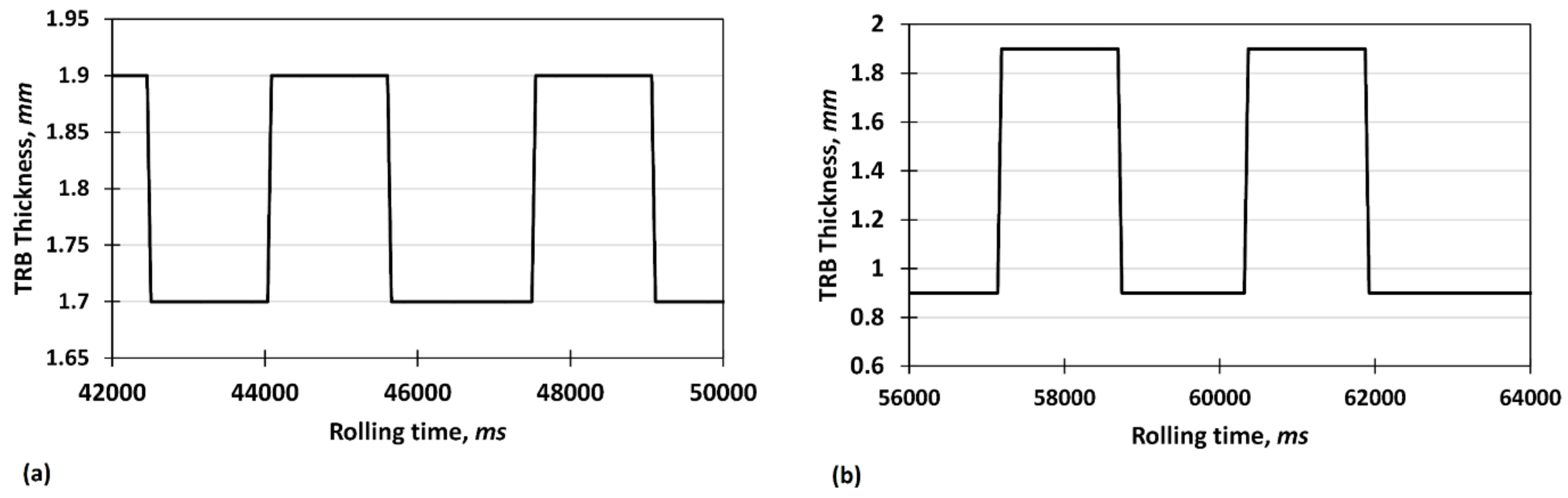
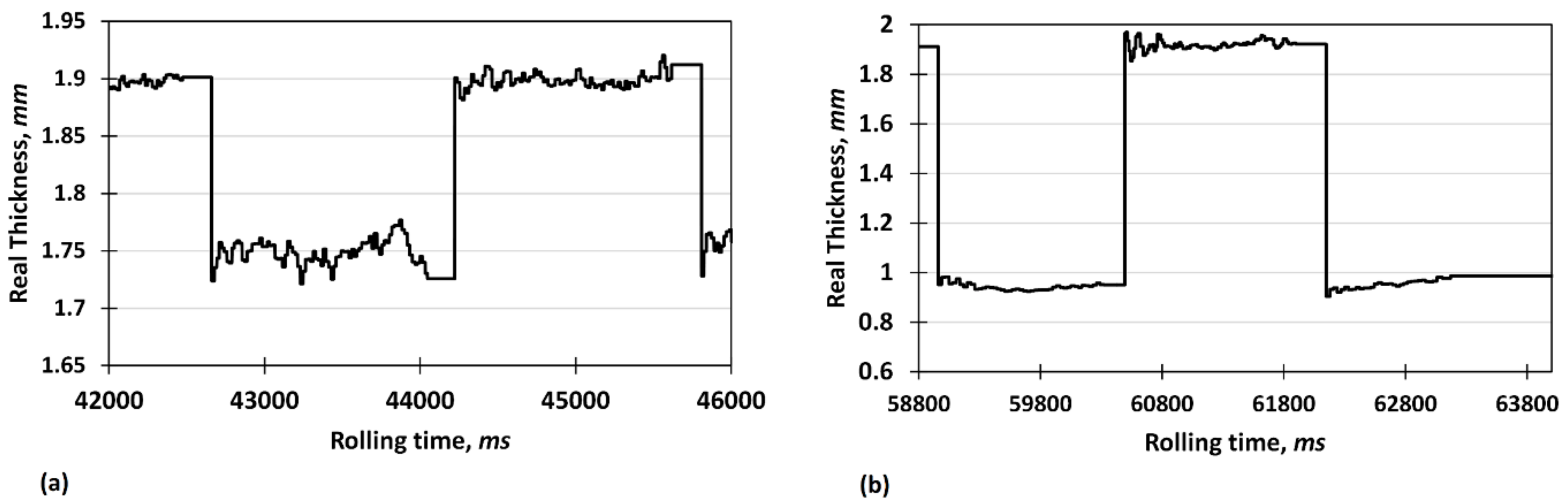
Figure 1a,b depicts the variations of the target thickness of TRBs vs. rolling time produced via the VGR process. As shown, two different thickness ratios of 0.89
and 0.47
were considered to evaluate the effect of thickness reduction on rolling force during the VGR process. Accordingly, to prove the accuracy of the VGR setup, the instantaneous thickness was recorded as shown in
Figure 2. Considering the target and real values of thickness, the maximum error associated with thickness changes is about 3.9%, which lies within an acceptable range. In addition, for both cases, the thickness accuracy decreases with increasing reduction after downward rolling due to an increase in rolling force and possible roll deflections.
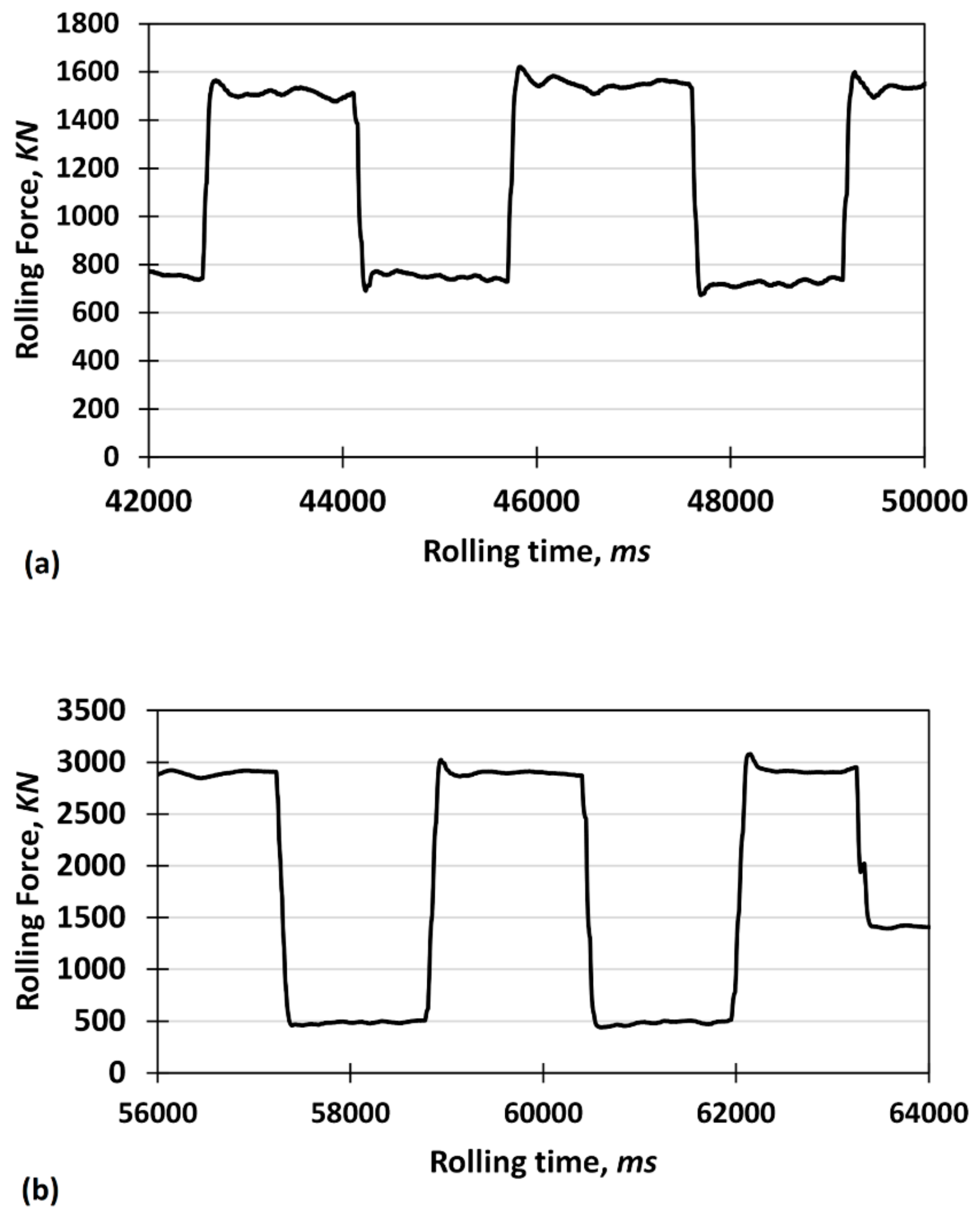
Figure 3 shows the corresponding rolling force vs. rolling time curves acquired during VGR of TRBs with thickness ratios of 0.89 and 0.47, respectively. It can be seen that the rolling force increases when downward rolling is performed; however, when downward rolling turns to flat rolling, the rolling force experiences a rapid drop. This rapid DRF is also detected when upward rolling turns to flat rolling to produce the thicker side. Furthermore, it is shown that the rolling force changes by a factor of two and six during VGR of the TRBs with thickness ratios of 0.89 and 0.47, respectively. These changes in rolling force can be simply attributed to the amount of thickness reduction and materials plasticity. However, the reason for the abrupt changes in rolling force in the outlet sections of downward and upward rolling is still ambiguous.
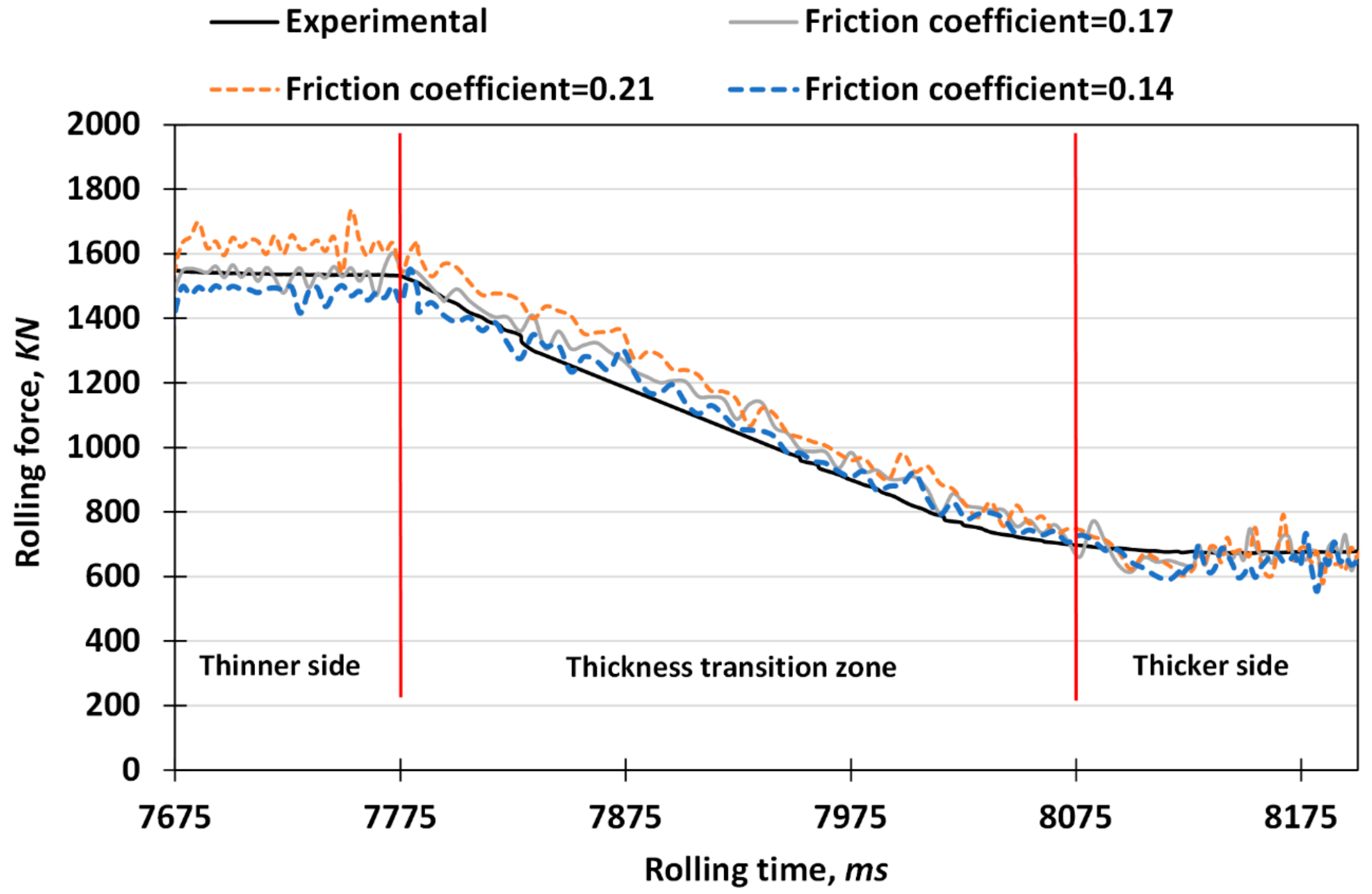
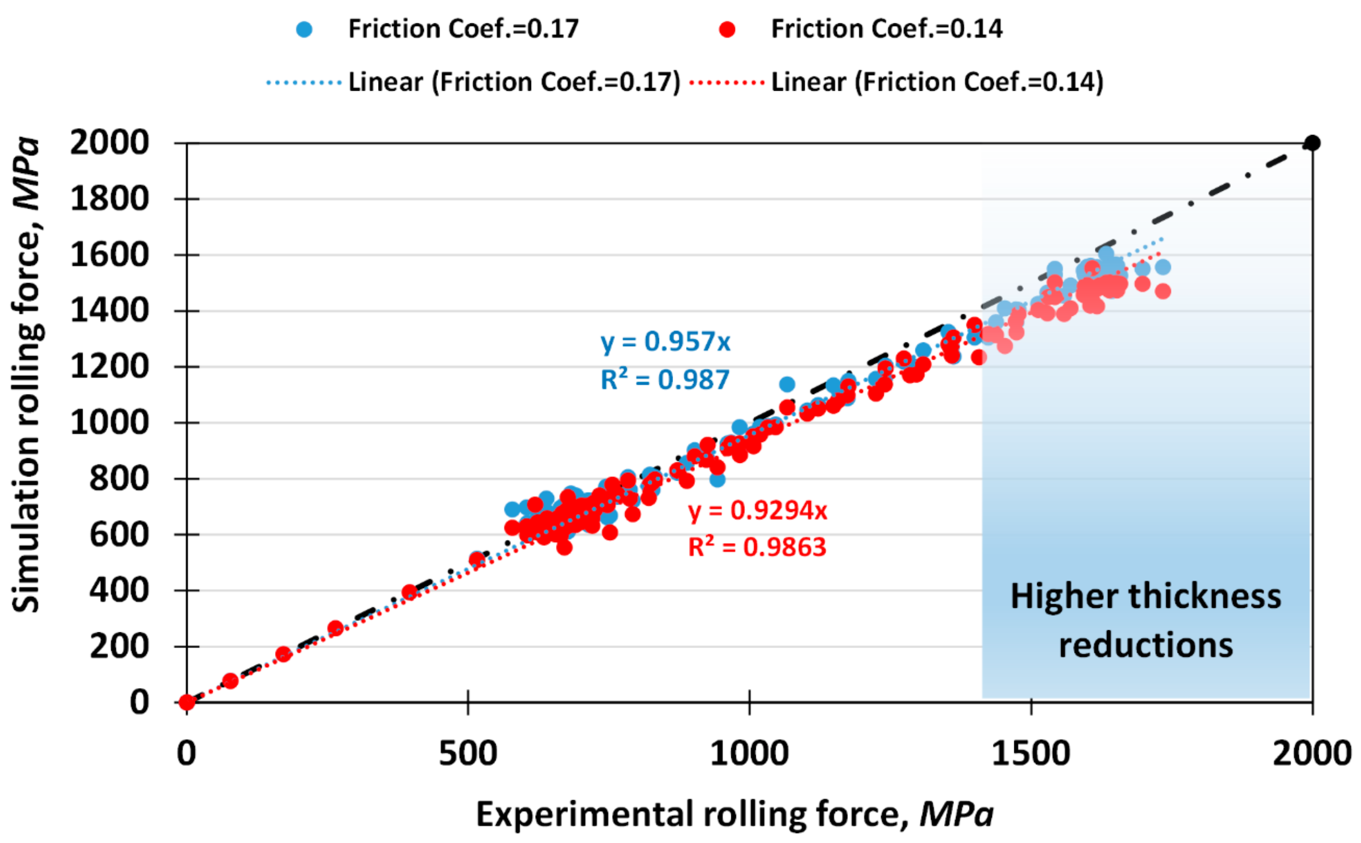
In order to evaluate the effects of other important parameters, including roll diameter and friction coefficient on the rolling force during VGR, FEM (finite element method) simulations were carried out. To this end, commercial ABAQUS/Dynamic Explicit software was used to predict the rolling force vs. rolling time curves during VGR at different deformation conditions. In this regard, the Von-Mises yield surface was applied to model the isotropic metal plasticity. In addition, an eight-node brick element with reduced integration (C3D8R) was used for the blanks, and the rolls were considered as rigid bodies. Furthermore, adaptive re-meshing was performed using the arbitrary Lagrangian-Eulerian (ALE) method to prevent mesh degeneration. The FEM simulations were first applied to estimate the friction coefficient during VGR. Accordingly, the VGR process was simulated with different friction coefficients of 0.14, 0.17 and 0.21 for the condition with a thickness ratio of 0.89. According to the results of simulations shown in
Figure 4, the highest degree of accuracy with respect to the experimental data was obtained for the condition with a friction coefficient of 0.17. It is notable to mention that the forward-backward pull tensions were 50 MPa (0.1× yield strength) to prevent sliding between rolls and the workpiece.
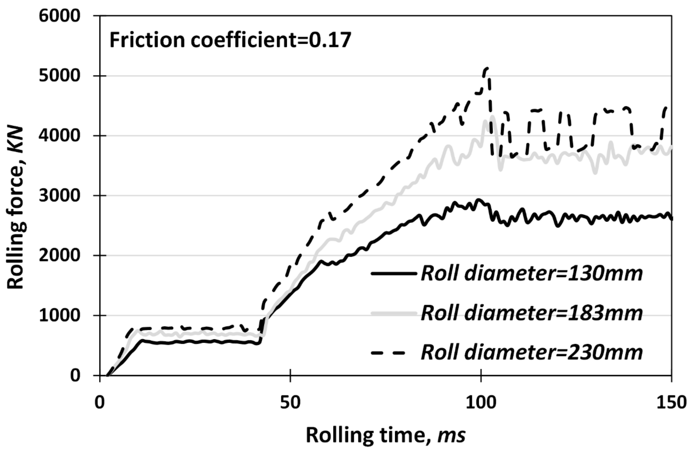
To study the effects of roll diameter on the rolling force and DRF during VGR, the condition with an absolute thickness reduction of 1 mm and friction coefficient of 0.17 was simulated with three different roll diameters of 130, 183 and 230 mm.
Figure 5 depicts the variations of rolling force vs. rolling time during both downward rolling and its subsequent flat rolling with different roll diameters. As shown, the rolling force increases with increasing roll diameters for both rolling stages due to an increase in the contact lengths. Furthermore,
Figure 5 also shows that the DRF value increases with increasing roll diameter.
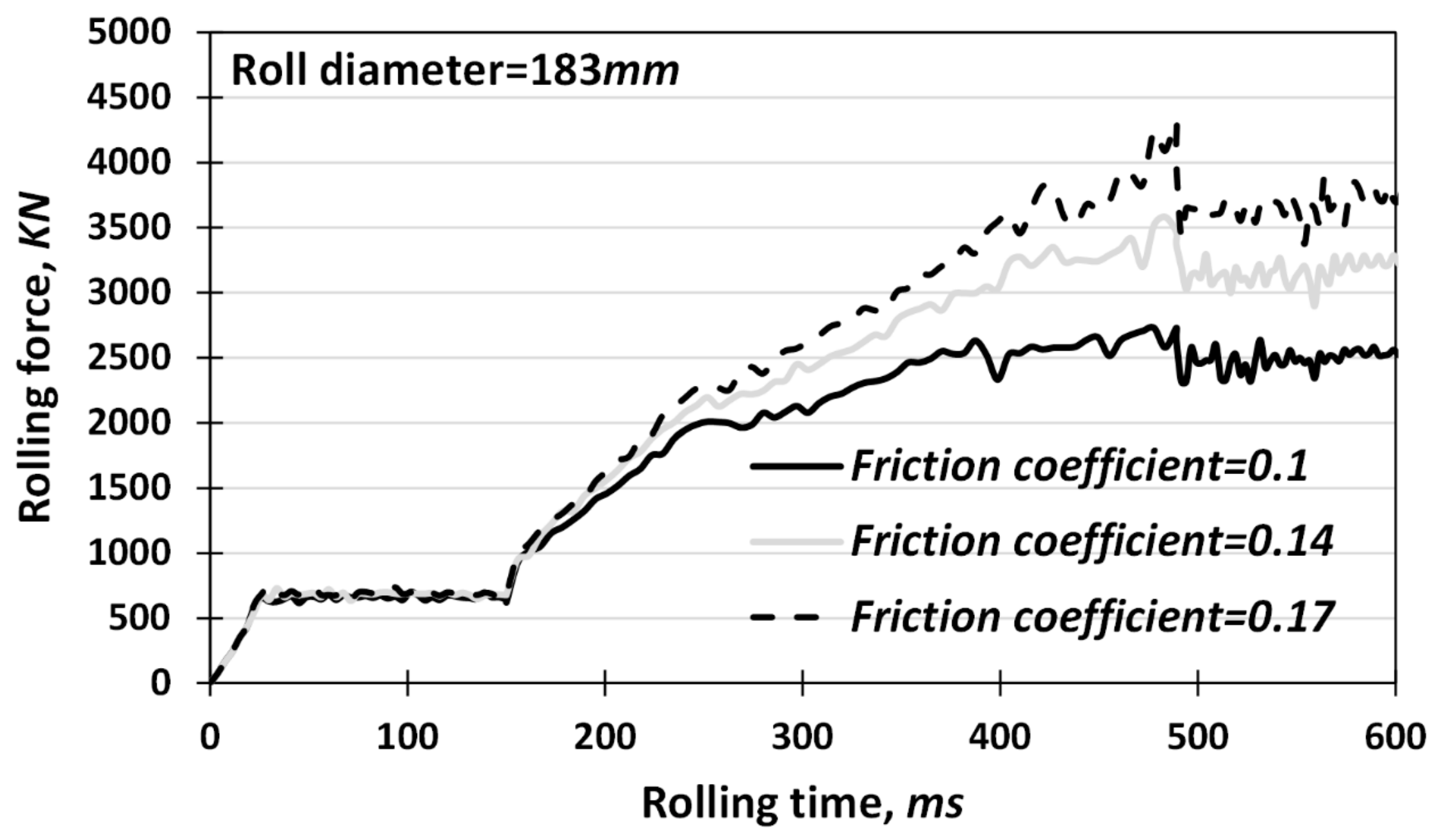
Figure 6 shows the rolling force vs. rolling time curves with different friction coefficients of 0.1, 0.14 and 0.17 and a constant absolute thickness reduction of 1 mm. As expected, the rolling force increases with an increasing friction coefficient. However, this increase becomes more evident in the outlet region of downward rolling due to the fact that the maximum rolling force is obtained in this region.
4. Discussion
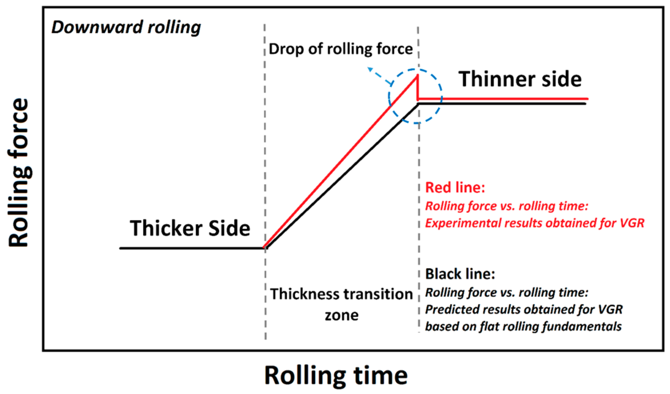
Figure 7 shows the variations of rolling force in the outlet section of downward rolling schematically. As shown, due to the occurrence of a DRF, the maximum needed rolling force exceeds the required rolling force needed to obtain the section with maximum absolute thickness reduction (thinner side). Liu et al. [
15] reported that this DRF is solely attributed to forward slip.
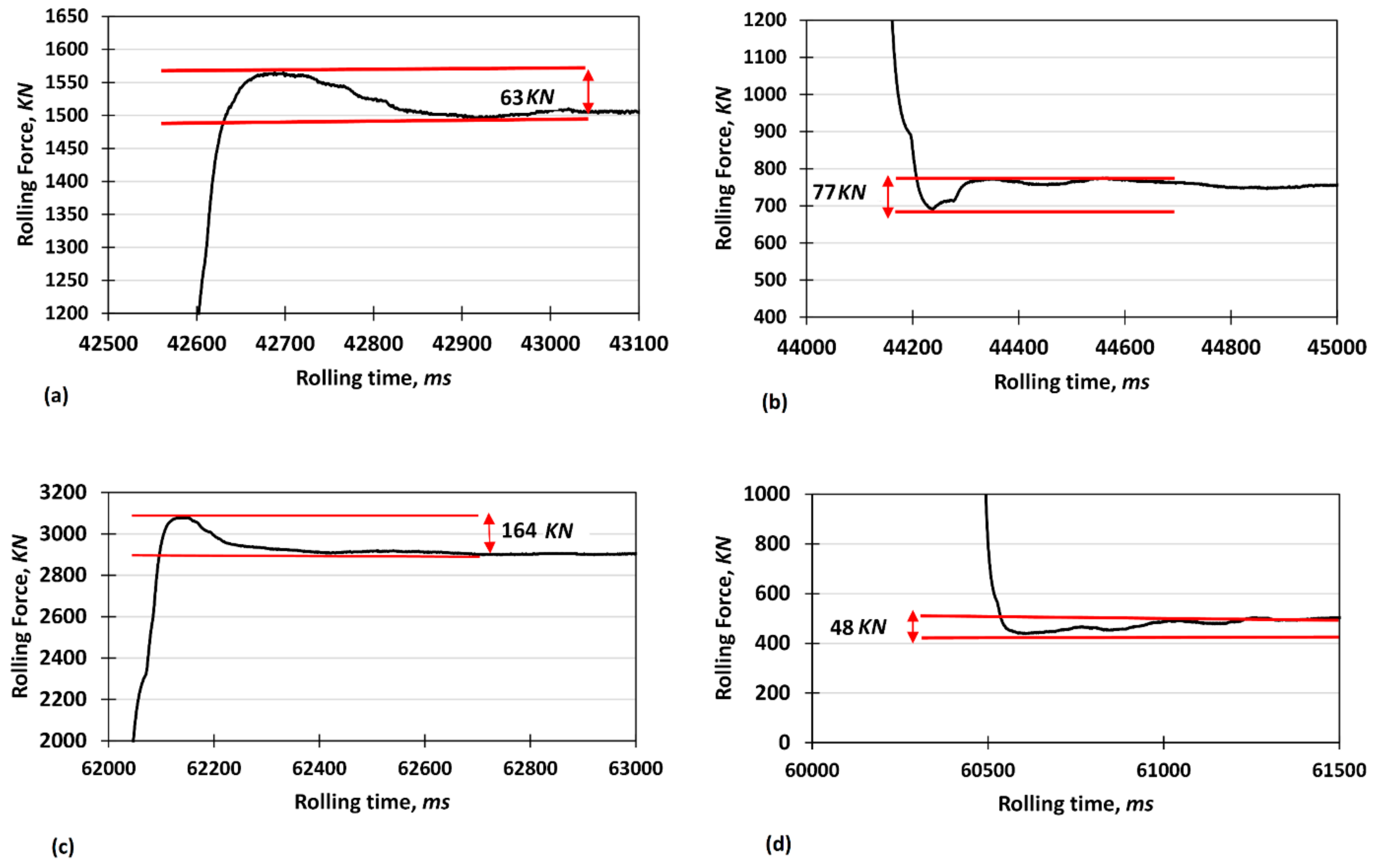
In order to clarify this issue, the variations of rolling force with time were studied at different reductions in more detail, shown in
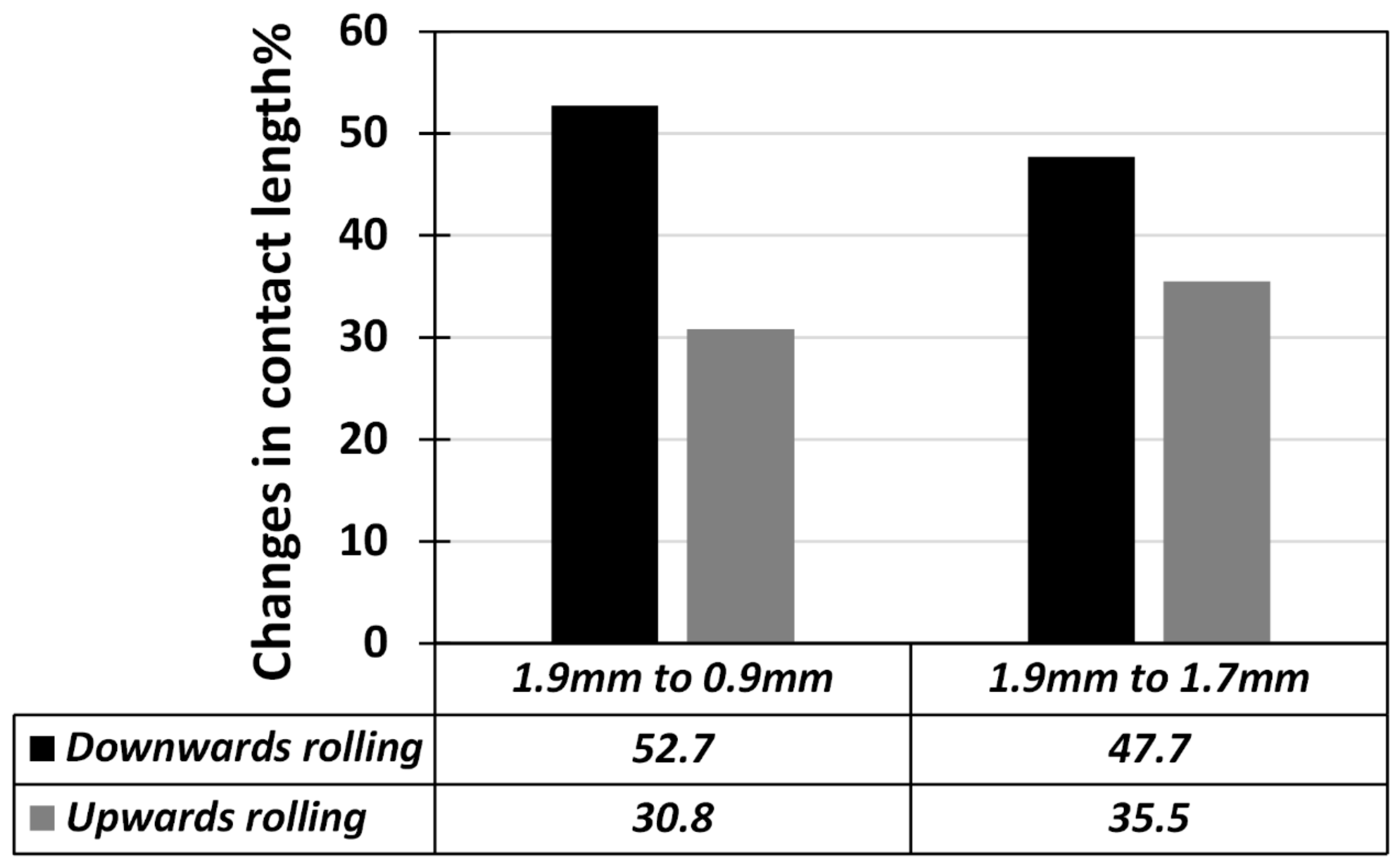
Figure 8a–d. In downward rolling, the DRF value increases from 63 KN to 164 KN for thickness ratios of 0.89 and 0.47, respectively. Furthermore, in upward rolling, the DRF values of 77 KN and 48 KN were obtained for the thickness ratios of 0.89 and 0.47, respectively. Accordingly, it can be concluded that in downward rolling, the DRF value increases with increasing thickness reduction and contrarily, in upward rolling, this value decreases with increasing thickness reduction. To justify these results, it is necessary to study the effect of the factors affecting rolling force in three successive sections of the VGR process. Accordingly, the effects of the changes in thickness reduction and roll diameter on the variations of rolling force were taken into account by considering their effects on contact length.
In flat rolling, it is widely accepted that the contact length can be obtained using the following expression [
17]:
where
R and
are roll radius and absolute reduction in thickness, respectively. It is notable to mention that the absolute reduction in flat rolling regions was obtained based on the initial thickness of 2 mm.
In contrast to flat rolling, the workpiece is out of touch with the rolls in upward rolling, and consequently the contact angle is smaller than the bite angle of flat rolling. Contrarily, the contact angle increases with increasing wedge angle (
φ) in downward rolling. Accordingly, the contact angle is bigger than the bite angle obtained in the flat rolling of the thicker part. According to the geometry of the deformation zone, the following expression can be used to obtain the contact length during upward and downward rolling:
where
φ is the wedge angle. It is worth mentioning that the wedge angle is a function of thickness reduction and length of the TTZ. Accordingly, for a constant length of the TTZ, the wedge angle increases with increasing thickness reduction (or decreasing thickness ratio).
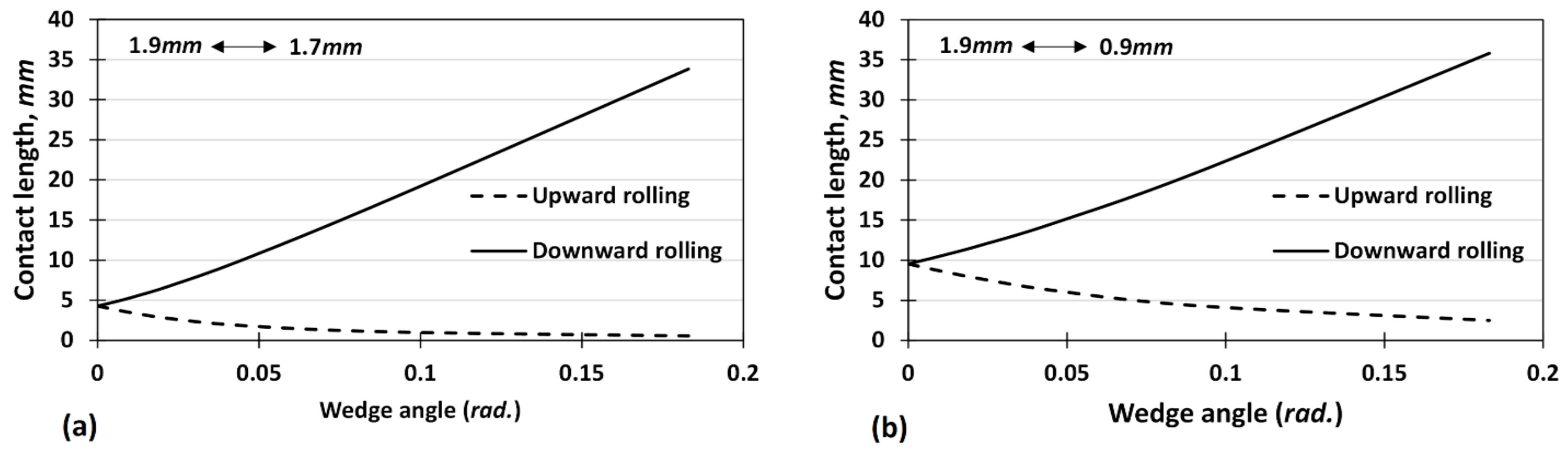
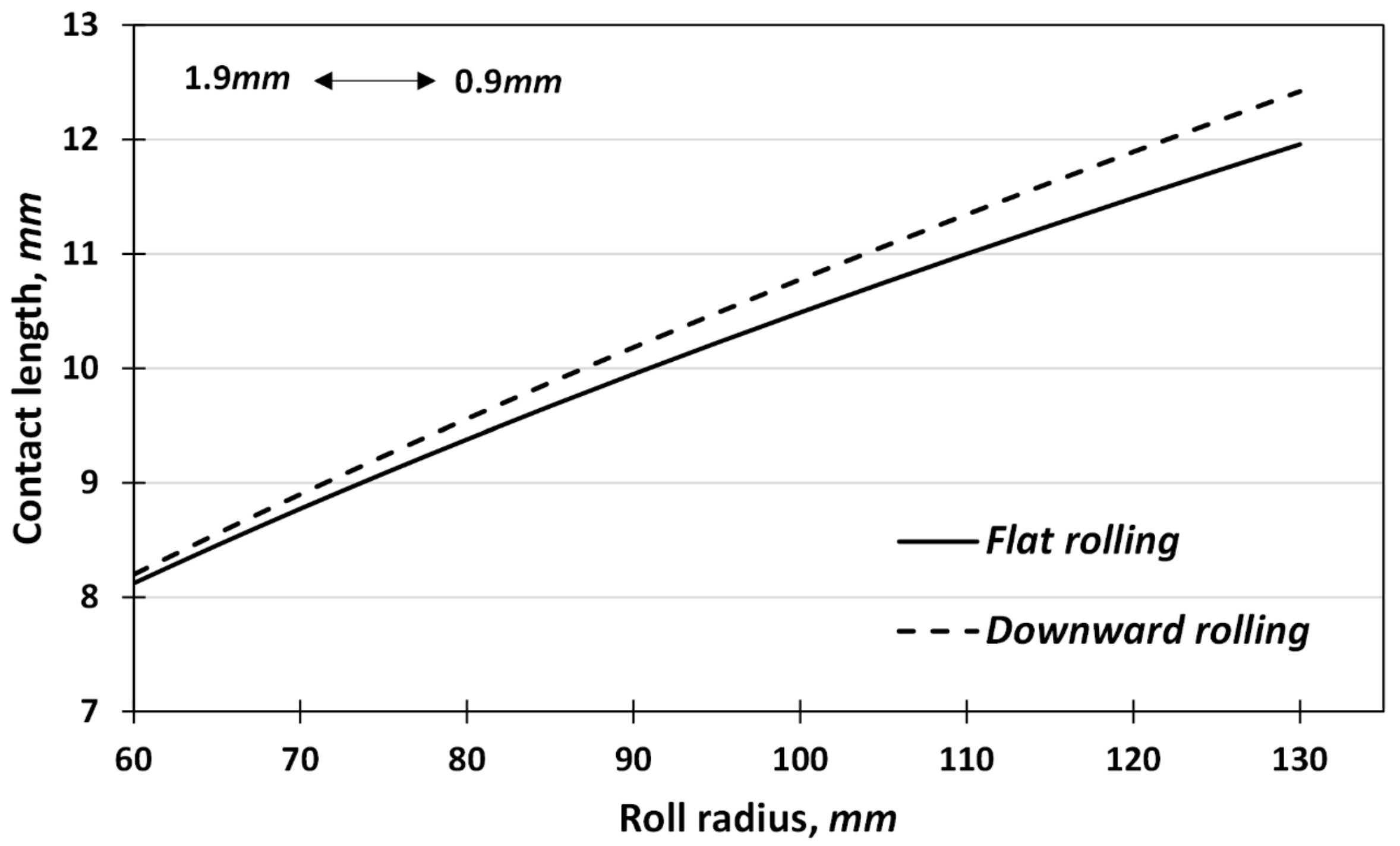
Figure 9 shows the dependence of contact length during upward and downward rolling for absolute thickness reductions of 0.2 mm and 1 mm, respectively. As shown, the contact length increases sharply with increasing wedge angle during downward rolling. In addition, it is clear that the contact length is more sensitive to the wedge angle for absolute reduction of 0.2 mm as compared to the condition with absolute reduction of 1 mm. Utilizing Equations (1) and (2), the changes in contact length for the studied cases in the outlet sections of the TTZ during downward and upward rolling can be calculated. Accordingly,
Figure 10 shows the effect of absolute thickness reduction on the changes of contact length in the outlet section of the TTZ. As depicted, the maximum and minimum values of these changes were obtained for downward and upward rolling with an absolute thickness reduction of 1 mm, respectively.
Since the rolling force is proportional to contact length, it can be concluded that the DRF in the outlet sections can be a function of changes in contact length as well. The variations of DRF in
Figure 8a–d prove the aforementioned claim. As expected, the maximum DRF value was obtained for the condition with higher changes in contact length during downward rolling. Similarly, the minimum value of DRF was obtained for the condition with lower changes in contact length during downward rolling. In other words, due to lower values of bite angle for the condition with an absolute thickness reduction of 0.2 mm, the contact length is more sensitive to the wedge angle and decreases more rapidly with an increasing wedge angle. Accordingly, a higher DRF value is obtained for this condition during upward rolling. Consequently, since the rolling force shows an abrupt change to a peak value before turning to flat rolling in downward rolling, it is essential to consider these changes when designing forming tools for VGR to obtain proper thickness accuracy.
In order to study the reasons behind the dependence of DRF on absolute thickness reduction and contact length in more detail, the slab method was used to model the variations of rolling force in the outlet section of downward rolling. According to the slab method, the rolling pressure required for flat rolling in the plane strain condition can be obtained as follows [
17]:
where
,
and
are average yield stress, friction coefficient and contact length, respectively. The values of
can be obtained using Equation (1). Furthermore,
can be calculated with respect to the thicknesses of the thinner and thicker sides along the longitudinal direction.
Substitution of
with the formulation derived for the VGR process (Equation (2)), Equation (4) can be rewritten to obtain the required rolling pressure during VGR as follows:
Accordingly, the DRF values in the outlet section of downward rolling can be obtained using following expression:
Substitution of Equations (3) and (4) into Equation (5) leads to the following expression for the DRF:
It is widely accepted that the friction coefficient is a reduction-sensitive parameter and may increase with increasing thickness reduction [
18]; however, for the sake of simplicity, a constant friction coefficient of 0.17 was applied for different thickness reductions during VGR. Furthermore, as the thickness reduction increases instantaneously along the TTZ, it was impossible to consider the friction coefficient as a reduction-dependent parameter; however, its changes along the rolling direction during VGR can affect the solution accuracy. As shown in
Figure 11, the accuracy in the estimation of the rolling force decreases with increasing rolling force (increasing thickness reduction) for both studied friction coefficients of 0.14 and 0.17. This can be mainly attributed to the reduction-dependent characteristic of the friction coefficient. In other words, underestimation of the friction coefficient at higher thickness reductions may result in less accuracy in rolling force estimation by FEM simulations.
Assuming a constant friction coefficient during VGR, the following expression can be obtained for the DRF:
As can be seen from Equation (7), the DRF is directly proportional to the changes in contact length. Accordingly, this can prove the competency of the analyses provided in
Figure 9 and
Figure 10 regarding effects of thickness reduction on the DRF.
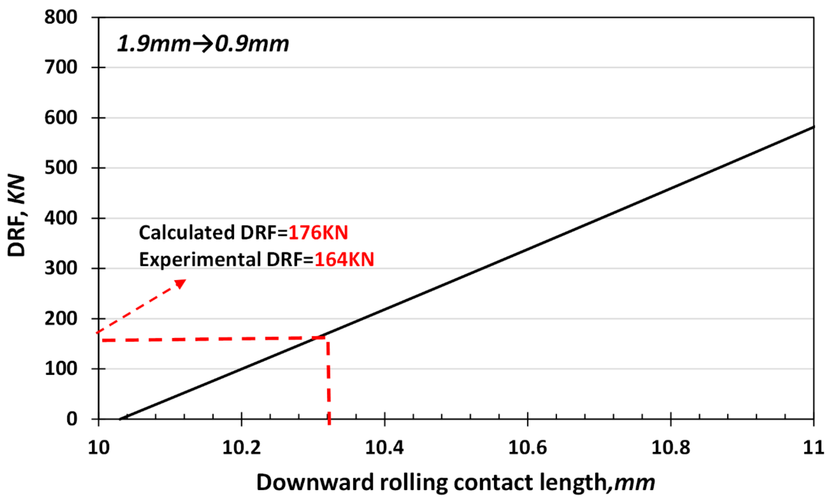
Figure 12 depicts the variations of the DRF as a function of downward rolling contact length (
) using Equation (7). As shown, a good correlation was obtained between the experimental results and the slab method analysis for an absolute thickness reduction of 1 mm.
Figure 13 shows the variations of contact length as a function of roll radius for the downward and the subsequent flat rolling stages at the aforementioned conditions using Equations (1) and (2). As depicted, the difference between the two contact lengths increases with increasing roll diameters, which leads to higher values of the DRF (See Equation (7)). According to the data provided in
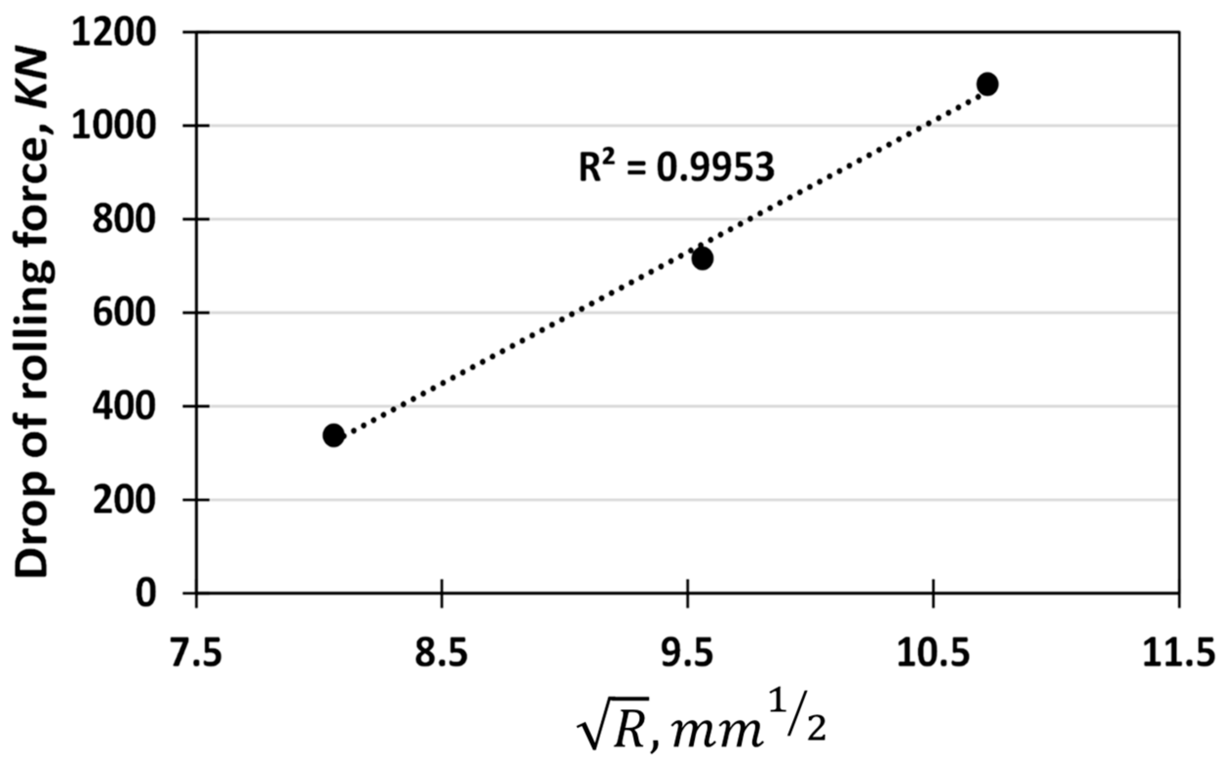
Figure 14, and with respect to Equations (1) and (2), it was found that the DRF is a linear function of
. The high correlation factor of 0.99 proves the competency of this regression analysis.
In addition, as shown in
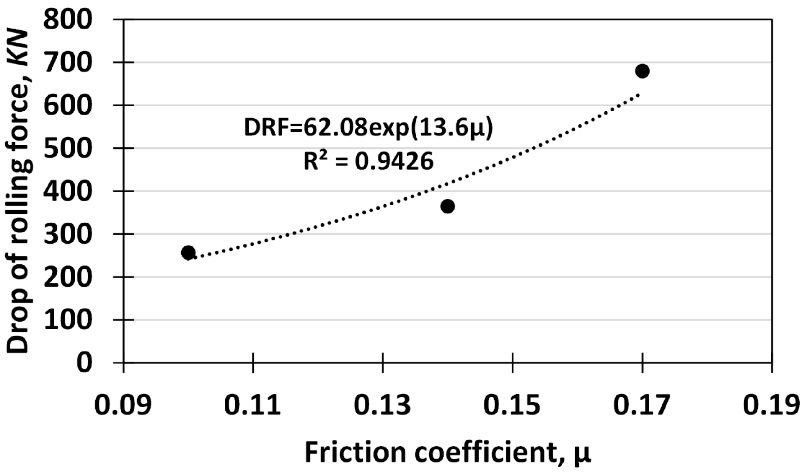
Figure 15, the rapid changes in the DRF are an exponential function of the friction coefficient. The reason for this phenomenon can be attributed to the changes in the vertical component of the frictional forces when the downward rolling turns into the subsequent flat rolling. Furthermore, variations of the friction coefficient with thickness reduction may have similar effects on the DRF, as per Equation (7).
In comparison with the results obtained by Yu et al. [
16], similar trends were obtained for the variations in the DRF with thickness reduction, roll diameter and friction coefficients. However, the magnitude of these variations are not comparable as their work was not validated with experimental data. Furthermore, they provide no reasons for these variations from a mechanical point of view.


