Article

Numerical and Experimental Analysis of the Gear Size Influence on Density Variations and Distortions during the Manufacturing of PM Gears with an Innovative Powder Processing Route Incorporating HIP

1
KTH Royal Institute of Technology, Brinellvägen 68, 100 44 Stockholm, Sweden
2
Swerea KIMAB, Isafjordsgatan 28A, 164 40 Kista, Sweden
*
Author to whom correspondence should be addressed.
J. Manuf. Mater. Process. 2018, 2(3), 49; https://doi.org/10.3390/jmmp2030049
Submission received: 3 July 2018 / Revised: 15 July 2018 / Accepted: 19 July 2018 / Published: 23 July 2018

Abstract

:
The paper is the result of research intended to develop a process route for the manufacturing of powder metallurgical (PM) gears for application in transmissions units for heavy duty powertrain applications. The main problem of PM for such applications is that the generated pores that occur through conventional pressing and sintering processes reduce the gear strength, which reduces the capacity for power transmission by the gear. In prior work, removing the pores and reaching 100% density by adding Hot Iso-static Pressing (HIP) after two times pressing and two times sintering steps in the process route was suggested to solve the mentioned problem. During the investigations of this work it was revealed that the gear dimensions could influence the process results with respect to geometrical distortions. In this paper we have presented a finite element (FE) model based analysis on how the gear geometrical parameters influenced the distortions occurring in HIP. The simulation model is validated with experiments. Furthermore, the simulation model is used to create a prediction model for further investigations. The research showed that PM gears with different sizes during the proposed process route behaved differently in terms of distortions. This was illustrated with a series of simulations with different gear geometries. A regression model was developed based on the FE results for further practical predictive use. The distortions caused by HIP should be considered in the process design to prevent expensive post processes afterwards to reach the gear with accurate geometry and keep the costs of manufacturing low. It is concluded that it is possible to use the innovative process route including HIP to reach the full density and close all the open pores but not for all kind of gear geometries.

1. Introduction

Powder metallurgical (PM) gears offer a number of benefits, which make them a sustainable alternative to the traditional gears made of wrought steel by conventional manufacturing processes. Among all of the advantages for PM gears, lower cost of production, lower amount of material waste in manufacturing, and the possibility to add new design features to the shape of the gear are the most mentioned advantages by PM researchers in the literature [1,2,3,4].
The lower density of PM gears manufactured by pressing-sintering process routes limits their applications for higher load transmission duties [5]. For such applications the full strength of steel is necessary from the PM process route in order to ensure the delivery of the required power transmission properties. Sintered PM gears have lower density than wrought steel, the pores remaining after pressing and after the removal of the lubricant during the sintering step of the PM processing is the root for the lower density in traditional sintering technology. The lower density causes problems when it comes to the fatigue loading and durability of the PM gears [6,7]. Therefore, reaching the full density for a PM gear is a vital pre-request to meet, before using them for high performance applications [8].
The processing route of PM gears of this paper is based on a two times pressing and two times sintering process route followed by a container-less HIP densification at the end [9]. In this process full density can be achieved [10,11]. The process steps are as shown in Figure 1.
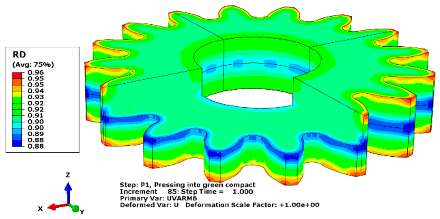
While reaching the full density of the gear after Hot Iso-static Pressing (HIP) is achieved, significant distortions occur during the HIP operation [12,13,14]. The distortions are caused by the inhomogeneous density distribution after the initial pressing steps [13,14]. Existing frictional forces between the powder particles and the die walls during the pressing of the loose powder cause the generation of a neutral zone in the middle surface of the gear face width, as shown in Figure 2. In the pressing step, where two punches are used to press the powder, a density gradient is obtained along the gear axial direction with the minimum densities located on the middle of gear axial direction. After the first sintering step of the PM gear the density in the neutral zone remains at the lowest levels while on the outer surfaces of the two ends of the face width the highest densities are observed [15]. This behavior remains in the PM gear through the second pressing and second sintering as well. Finally, lower density in the neutral zone will cause larger distortions in the HIP densification step. The distortions are critical with respect to the complex geometry of the gears. Generated distortions after HIP have to be compensated in a finishing operation.
The importance of reaching the right tolerances of the gear dimensions after the suggested process route, brings the necessity to analyze the distortions of PM gears in the HIP step and develop a predicting model for it. The model can be used for further developments to optimize the design of PM processing for the manufacturing route in Figure 1.
In this paper, a combined numerical and experimental method is used to analyze and evaluations are focused on the dimensional distortions caused by the process route shown in Figure 1. The main aim is to understand the relations between the gear geometrical parameters and the generation of the neutral zone and consequent distortions occurring in the HIP process. Validated FE simulation results can enable us to propose a predictive model to follow the component density developing during the process route in Figure 1. The present authors have previously evaluated the effects of gear geometry on the pressing of PM gears and they have shown that different gear parameters could result in different density gradients in the PM gear [15]. In the present paper, the influence of two parameters, which are defining the gear size, are considered for the analysis. The first parameter is the outside diameter of the gear (da) and the second parameter is the face width of the gear (b). The outside diameter is a function of the gear normal module (mn) and the number of teeth (Z), as shown in Equation (1):
d a = f ( m n ,   Z ) ,
Therefore, the main independent variables of the analysis to develop the predictive model are normal module (mn), number of teeth (Z), and the face width (b) of the gear.
The next section will explain the conducted experiments, which were used to verify the simulation model. The details of the tested sample gear geometries were given. Then, in the next section, the numerical simulation of process steps is presented by explaining the material model, material parameters for the simulations, boundary conditions, and the frictional model used in the simulations. After explaining the experimental and numerical procedures of the research, the experimental results and numerical simulation results are presented together in the results section to validate the simulation model. The relations between the gear geometrical parameters and the distortions caused in HIP of the PM gears are studied in a subsequent and separate section. The verified model is used to predict the different effects of the geometrical parameters of the gears in the following section. A discussion section together with final concluding remarks are presented in the last two sections to deliver the main findings and contributions of the research work.

2. Experimental Procedure

In this chapter of the paper, details about the experimental tests performed in the research to manufacture two different gear geometries based on the proposed process route is explained.
Gear function requires case hardening and high core toughness. For such requirement PM gears require to have high compressibility and homogenous microstructure after sintering. For this purpose, the water atomized steel powder manufactured by Höganäs AB in Sweden is used for the investigations of this work. This powder has a good compressibility as well as hardenability. The powder is pre-alloyed with 1.5 wt. % Mo (Astaloy Mo). The powder has standard powder size fractions within the range of 20 to 180 µm. For the experimental tests, powder is admixed with 0.6% LubeE for lubrication and 0.2 wt. % of graphite to add carbon to the mixture [16].
As mentioned in the introduction, the processing route for the production of gears from metal powder consists of five processes (see Figure 1). The first step (P1) is to press the loose powder into the so called green component. This process is performed by mechanically pressing of the powder. For this process two punches press the powder to the near net shape of the gear. The second step (S1) is to sinter the green component. This step is a thermal process to remove the lubricant from the powder. Naturally in this process, the removal of the lubricant will create pores in the component, which could be the source of further problems in the processing of PM gears. To increase the shape accuracy and reach higher levels of density, one more cycle of pressing and sintering is considered in the processing route. Second pressing (P2) is also performed using a mechanical press. The main difference between first pressing and second pressing is the amount of deformation, which is limited in the second pressing. During P2 and the subsequent sintering, S2, a further reduction of porosity will occur and the pores will become rounder in shape. The shape of the component will become closer to the intended shape before HIP. After the second sintering the gear should reach a relative density of some 90% or higher everywhere in the gear in order to avoid open porosity [17,18]. Such an open porosity must be avoided during the final HIP stage since no densification can occur if the gas in the HIP chamber can penetrate into the inside of the material through open pore passages. The HIP gas is only allowed on the outside of the component during the HIP step. This is a very critical requirement in the present process route where no container is used outside each gear wheel. An individual container could prevent the HIP gas from penetrating into the gear, however, such a container is much too expensive to be acceptable in the present process route. For the investigations presented here, all the mentioned steps are performed experimentally to manufacture two different gears as a reference for the development and verification of numerical simulation model. The first and second pressing steps are performed at 800 MPa press. The first sintering is performed at 800 °C in N2 atmosphere for 1 h and the second sintering is performed at 1300 °C for 1 h in vacuum. HIP is performed at 1150 °C for 2 h and by applying 100 MPa of pressure using Argon gas.
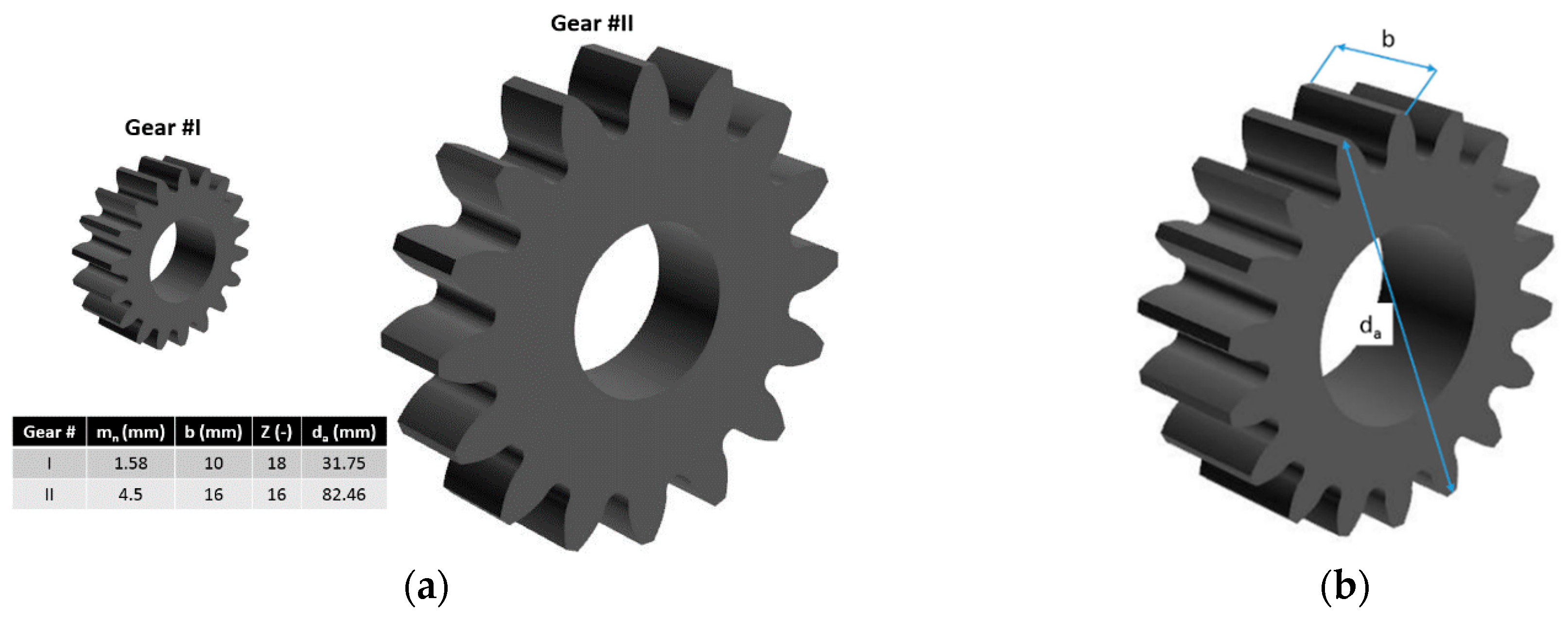
Two types of gears, Gear I and Gear II, are manufactured using the explained process route above. The gears have different design parameters and their specifications are given in Figure 3a. The experimental results obtained from manufacturing of these gears will be used in the next section to compare and validate the numerical simulation model. As the focus of the investigation is on the gear size influence on the geometrical distortions in the manufacture of PM gears by the proposed route, it is necessary to define measuring references to measure the influence of the gear size parameters on the results of the PM processing route under discussion in this work. For this purpose, two dimensions of the gears are selected to be followed, as shown in Figure 3b. The first dimension is the gear outside diameter, which is also referred to as the addendum diameter (da). The second dimension of the gear is its height, which is referred to as the face-width (b) of the gear. These two dimensional parameters are measured in experiments after each process step. The measurements were all done using a digital micrometer that presents a value within 1 μm. In addition, the component average density is measured using the Archimedes principle after all steps. For measuring density after P1 to avoid penetration of water into the open pores the component surfaces are sealed and the density is measured. The density measurement accuracy is around 0.03 g/cm3. All of the measurements are performed on three samples of Gear I and Gear II. The averaged values are reported and used in the paper.
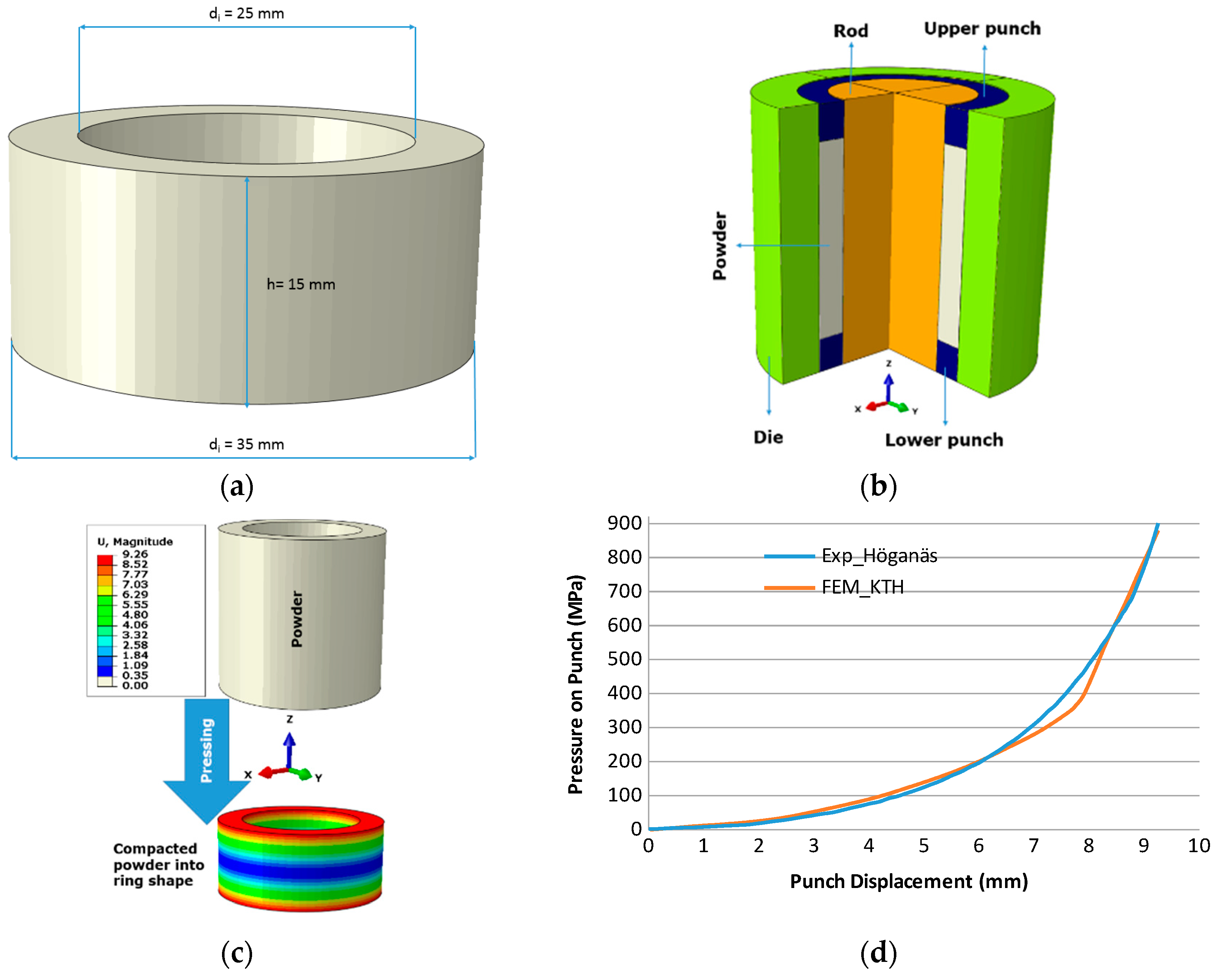
To improve the material modelling accuracy, one experiment is performed to compress the powder behavior during compaction. The ring shape component with the dimensions given in Figure 4a, is used for this experiment. Then the powder is compressed using the mechanical press with two punches and the force-displacement curve for the test is recorded. To calibrate the material model parameters, the same process is simulated numerically as shown in Figure 4b and optimized until a good fit for the material hardening curve between the experiments and simulation is achieved, as shown in Figure 4c. Later on, in the simulations of the PM processing for gears with the same hardening curve for powder in the simulation of the first pressing are used in the numerical model.

3. Numerical Simulation

In this chapter, the numerical model is described with respect to the material modelling, friction modelling, boundary conditions of the model, and the geometrical modelling to simulate the experiments in order to develop a validated simulation model for further analysis.

3.1. Material Models

The first process is to press the loose powder into the green component (P1). For simulation of this step the modified Drucker Prager model (CAP) has been used [19,20]. To define the CAP model, the CAP parameters are taken from [21] and are given in the Table 1. Also, to describe the powder hardening curve in the CAP model, the fitted model that was created from the results of ring compaction and explained in experiments is used as the input for the numerical simulation model (see Figure 4c).
The results of the experiments showed very small deviation in the geometry and average density of the component after both of the sintering process steps (S1 and S2). Therefore, the effect of sintering processes are just taken into account by a linear modification factor applied over the Relative Density (RD) distribution in the numerical simulation models. This is performed by applying the experimental factor on the output of P1 for the RD distributed on the mesh nodes, and using it as the input for P2. The same procedure is repeated again by applying the experimental factor for S2 on the output of P2 for the RD distribution on the mesh nodes and using it as the RD input for the HIP simulation.
After first sintering (S1), the powder particles are bonded due to the high temperature in the sintering furnace. Therefore, the CAP model for loose powder could not be used anymore in the simulation of the second pressing (P2) and neither for HIP. Hence the material model needs to be changed to a model for the modelling of porous metals. In this work the Gurson model is used for the simulation of P2 and HIP [22]. In that model all the pores are considered to be spherical [22,23,24].

Material Model Parameters

Table 1 presents the parameters used in simulations of P1 for CAP plasticity and Table 2 presents Gurson parameters for P2 and HIP. Table 3 presents the modification factors applied on the RD distribution after P1 and P2 to consider the sintering effects, which are recorded from experimental data from S1 and S2 and are considered as a constant change factor for the simulations in the rest of this work.

3.2. Geometrical Modelling

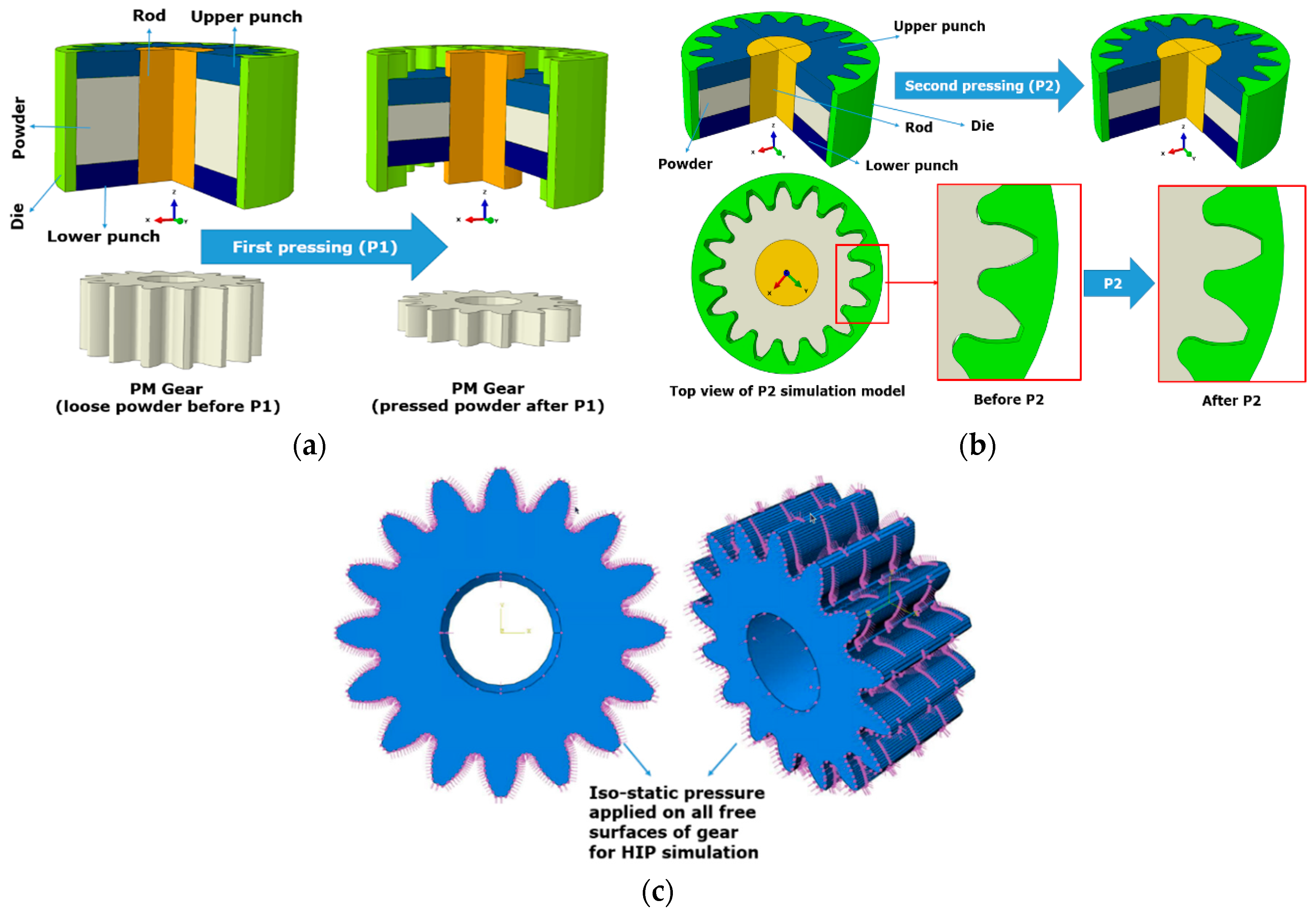
The 3D geometrical models of the dies and punches for the processes are created by using dimensions of dies and punches in the experiments for the two types of gear used: Gear I and Gear II. The simulation models for P1, P2, and HIP are shown in Figure 5. The details of the geometrical models are exactly the same as the experiments to ensure the validity of the simulation model with respect to dimensions and tolerances.
In first pressing (P1), a displacement controlled compaction of the powder is defined. The amount of displacements are controlled based on the initial powder density and the required height of the green component after P1. For the second pressing (P2), a displacement controlled motion of the dies is also applied. For HIP densification the material strength in high temperature is considered while a uniform normal pressure has been applied on all the gear surfaces to simulate the HIP conditions.

3.3. Friction

The Columb friction model is used for considering the friction between dies and punches and the powder particles in P1 and also the sintered component surfaces, punches, and dies in P2. The friction coefficient for Columb model was the same in the ring specimen compaction experiment and in all other simulations. The Columb coefficient of friction was set to 0.2.

4. Results

In this section, the results from the experiments and simulations are presented together to check the accuracy of the simulation model. Subsequently the simulation model will be used to predict distortions for a range of gear geometries in the next section. The results are based on the measurements from the experiments and also the simulation models for the same two gears in the FE simulation.

4.1. Average Density Results

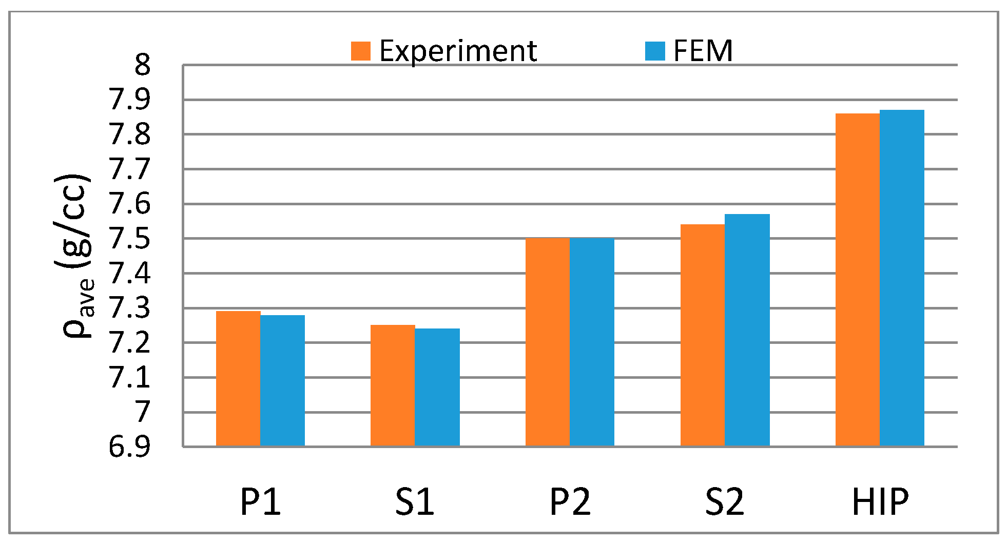
Figure 6 shows the results from experiments and simulations of the average density for Gear I. There is a good agreement between the experiments and simulations. The same applies to Figure 7, which shows the average densities for the Gear II.
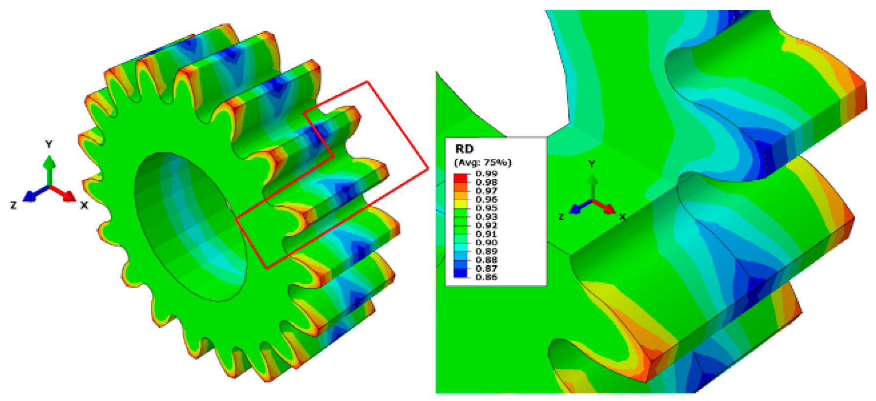
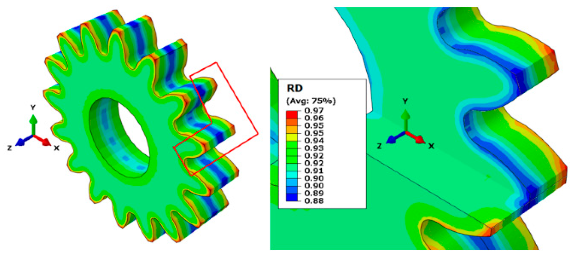
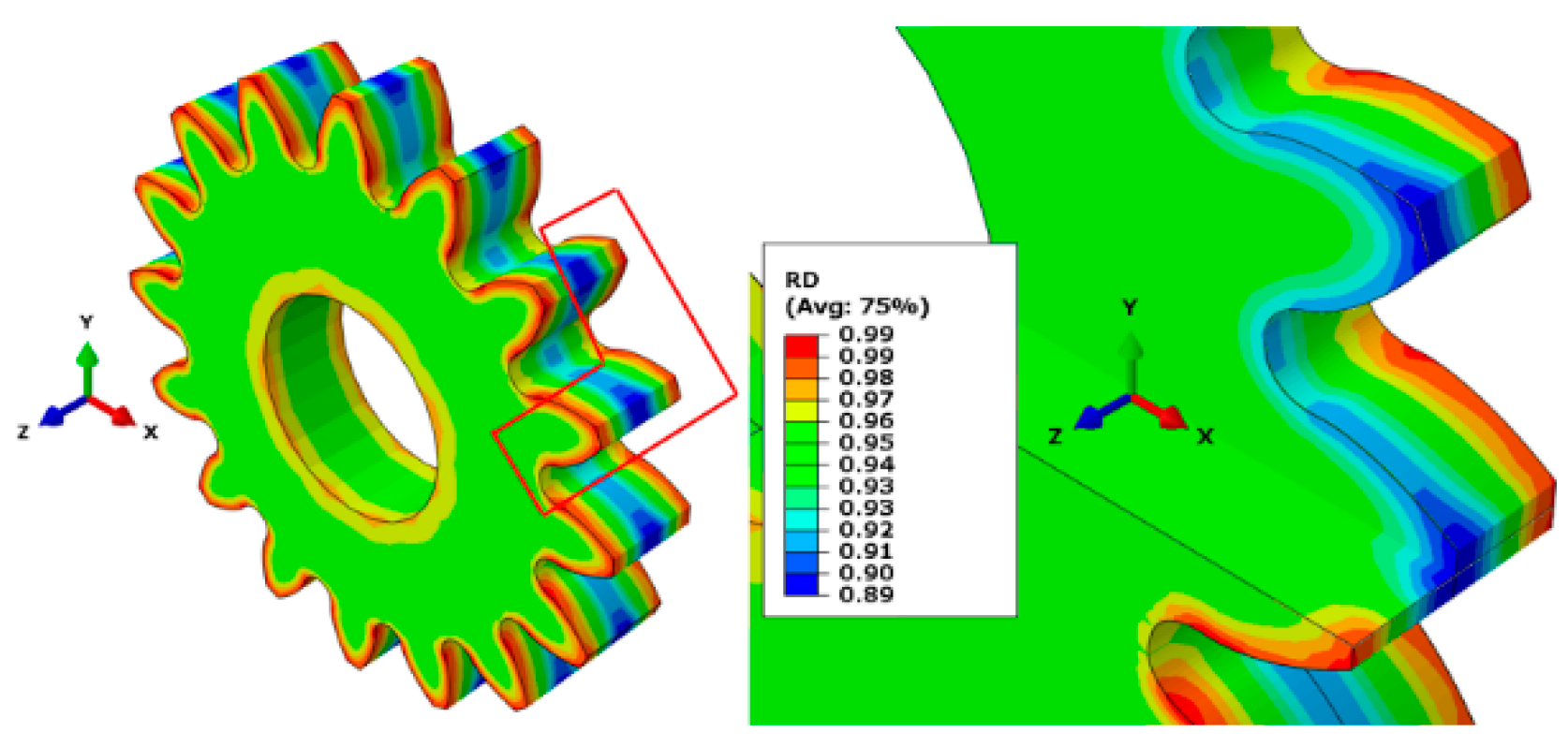
The density prediction accuracy is important since it could be a sign for the correct characterization of the material response in different steps of the process route. For both gears, as shown in Figure 6 and Figure 7, after P1 the predicted density is very close to 7.3 g/cc. This means the average relative density is higher than 90%. But from the simulation results, it is observed that it does not mean that 90% is reached everywhere in the gear wheels. Actually, close to the neutral zone of the gear, the relative density is slightly lower than 90% for both of the gears, as shown in Figure 8 and Figure 9. This shows the importance of the simulation model, where it is possible to see the density distribution in the component but not just the average density, which is possible to be measured from experiments.
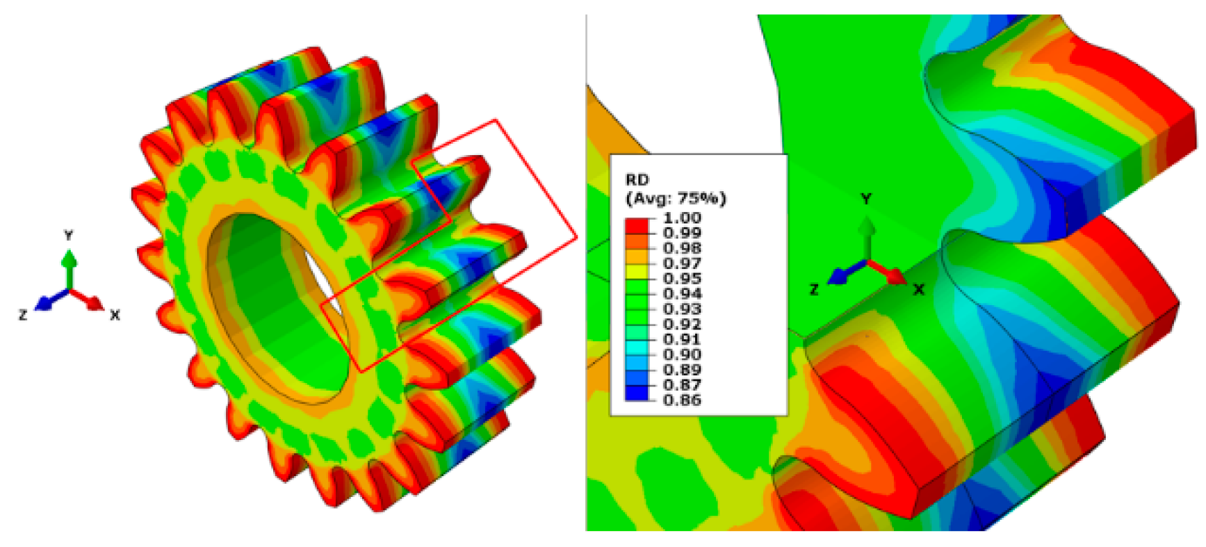
For the second pressing (P2) as it is illustrated in Figure 6 and Figure 7, the average density measured from the experiment is very close to the average density calculated from the simulation model. Here, the average density of 95% is achieved for both of the geometries in experiment and simulation. Again the results of the simulation could give better insight to the density distribution as shown in Figure 10 and Figure 11. The interesting observation is that for the two different geometries the lowest achieved density in the neutral zone of the gear is different. Therefore, even though the same process and material and temperatures are used for P1, P2 and S1 and S2, the results for density distribution in different geometries varies. This observation will be discussed later.
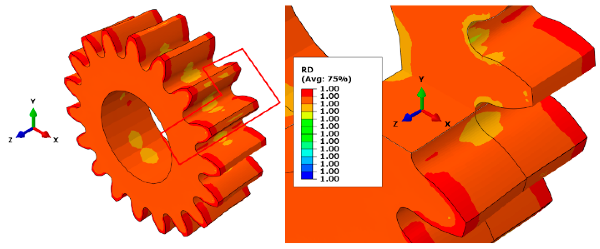
Looking at the HIP results, it is observed that in both gears it is possible to reach the full density of 7.89 g/cc. The same is recorded from experiments while the results for Gear II shows slightly higher average densities, which could be caused also from the gear size effects since all other variants in the two gears are similar. The results from the simulation for HIP are also shown in Figure 12 and Figure 13.

4.2. Geometrical Results

4.2.1. Addendum Diameter Variations

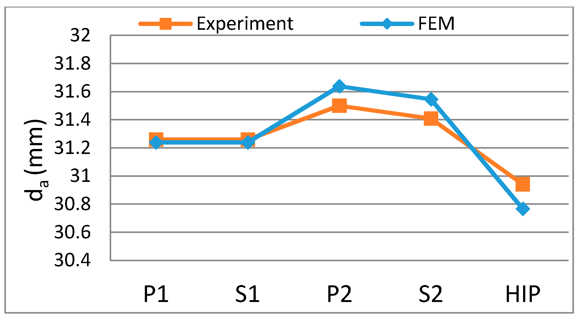
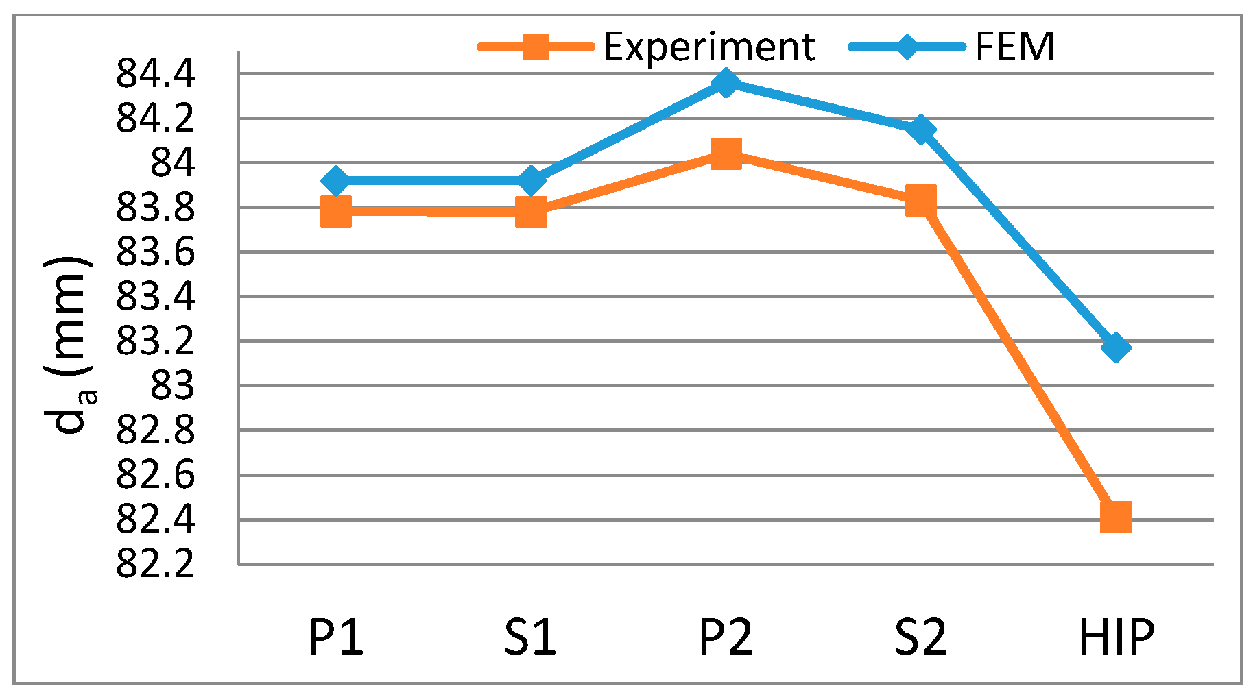
Figure 14 and Figure 15 show the variations in addendum diameter (da) for Gear I and Gear II, respectively. In both Figure 14 and Figure 15, the measurements from experiments and also the predicted values from the FE simulation are shown. Similar to the density results, here we observe good prediction accuracy for the simulation models for all steps of the process route. The increase in the addendum diameter observed in the second pressing (P2) is due to expansion of the sintered component in the die. This expansion is possible since there is a gap that exists between the die wall and the outer surface of the sintered component in P2. This is to ensure reaching the net shape after HIP and is a process design technique, which is not part of our investigation. The reduction observed in both Figure 14 and Figure 15 during the HIP step is the “distortion” caused by HIP on the outer diameter. This is a drawback of the suggested process route. Therefore, the aim here is to be able to follow this sort of distortion in our further analysis of the gear size influence on the geometrical distortions. It can also be observed that the variations in gear diameter are small during S1 and S2, as shown in Figure 14 and Figure 15.

4.2.2. Face Width Variations

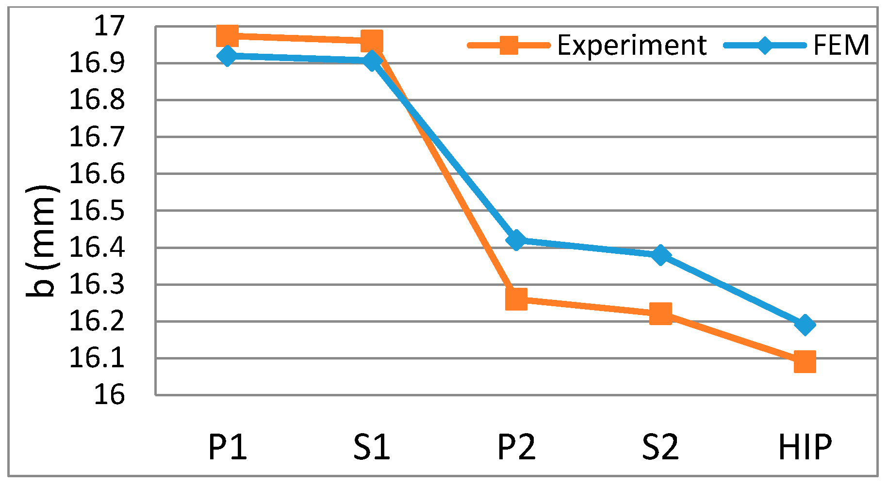
Figure 16 and Figure 17 show the variations in the face width (b) of the Gear I and Gear II, respectively. The numerical simulation model as well as the experimental tests for both pressing steps of the powder (P1 and P2) are displacement controlled. Since the starting height of the powder in both gears is the same as the starting height of the powder, as in the experiments, it is expected that accurate results on face-width after P1 and P2 in both simulations will be achieved. This is confirmed by looking at the results shown in Figure 16 and Figure 17. As explained earlier, the FEM model for S1 and S2 considers the density changes but neglects the dimensional variations. This assumption is confirmed with the experimental results of S1 and S2 on the face-width (b) variations. It is shown that the changes in face-width are very small during the sintering processes and therefore the suggested linear modification to apply on the density distribution can be a reasonable approximation. The last point to discuss from the results of the face-width variation is the “distortion” caused by HIP. As it is illustrated by both Figure 16 and Figure 17, similar to the addendum diameter, the face-width (b) will experience some distortions during the HIP, which should be considered in the process design. Comparing the results from the simulation and experiment in both gears confirms that the simulation model can predict the face-width (b) variation with a good approximation. Therefore, it is possible to use the simulation model for the later prediction of the geometrical distortion caused by the process for different gear sizes and make some predictions based on the model presented here.

4.3. Validation of Numerical Simulation

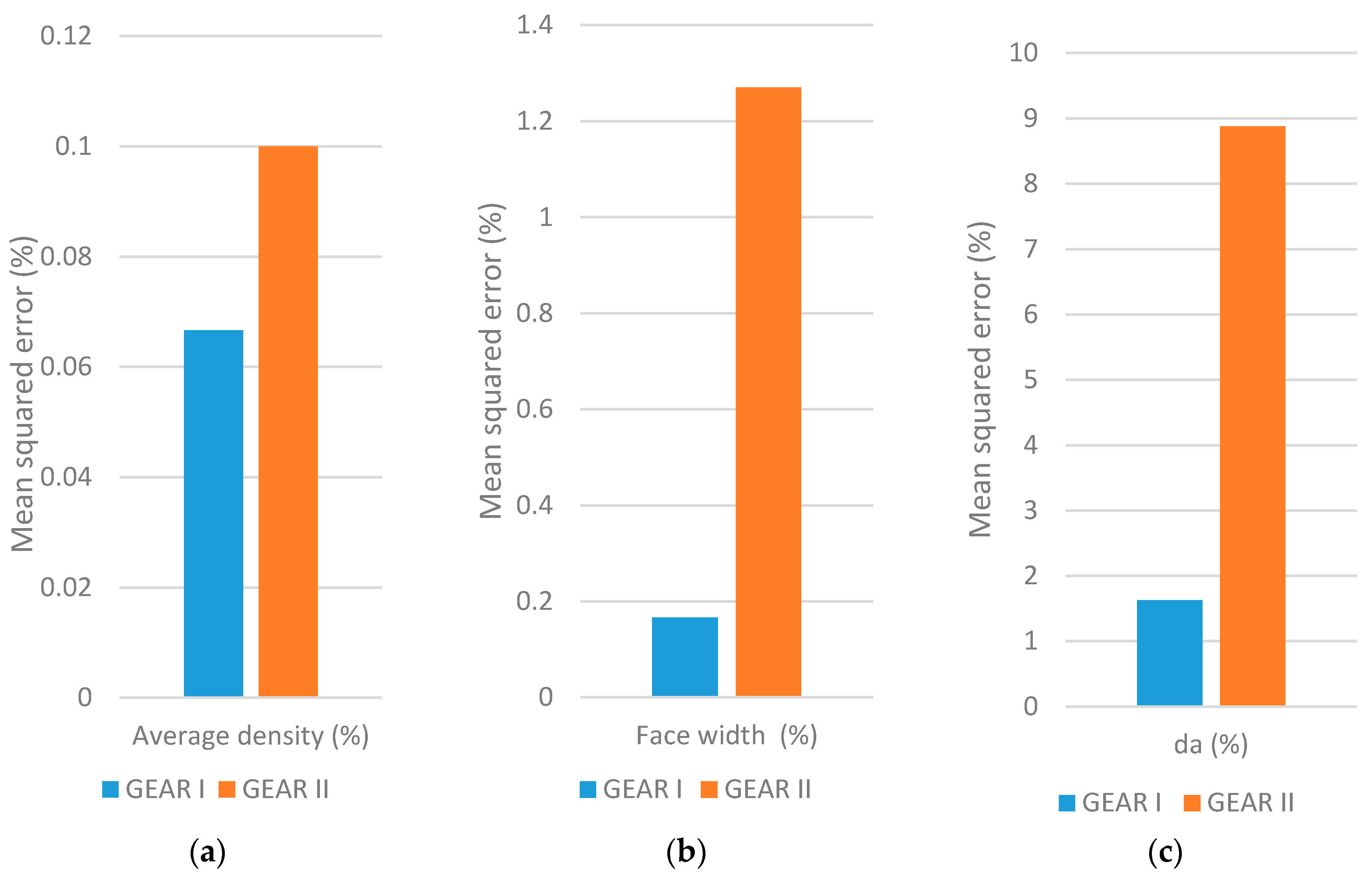
The comparison of experimental results and numerical results is performed for the predictions on the addendum diameter (da), face width (b), and average density (ρave) of the two experiments and their respective simulation models using the mean squared of errors (MSE) percentage. The MSE results for Gear I and Gear II are shown in Figure 18.
In Figure 18, the average density prediction results show high accuracy for the prediction of densities with error in the order of 1%. This amount of error validates the material model parameters in the simulations as well as the fitted hardening curve used in the simulations of the present work based on the experiments. This means the simulation model could be a good tool to analyze and investigate further geometries without performing experiments necessarily.
The important aspect of the simulation models presented here is to build a tool for the prediction of distortions caused by PM processing steps from the route under study in the research. For this purpose, in Figure 18 the results of deviation for the addendum diameter (da) between the simulation and experiment together with the results for the face-width (b) deviations between the simulation and experiments are given. As explained earlier, the trends in behavior is well predicted for both of the parameters in all the process steps.
The MSE of the prediction is very low for face-width (b) and in the order of 1%, as shown in Figure 18, which is very good. The MSE value for the prediction of the addendum diameter (da) is higher and in the order of 10%. This is still acceptable considering the expected errors from the nature of the numerical simulations. In the simulation models of this work a mesh density of 1 element per 1 mm in face-width direction is used, while on the cross-section direction the mesh density is lower, at 1 element per 2 mm. The difference is to control the model size and the computational cost and keep the model converging, but one way to reduce the amount of MSE for the predictions of the addendum diameter (da) is to increase the mesh density on the cross-sectional area and especially on the teeth of the gears so the contact condition can be modelled more accurately. This is a normal routine in FEM based models where finer mesh can result in a more accurate result. However, since in this work the distortion trends and the influence of the geometrical parameters on this trend is under focus, the presented model could be a valid model since certainly it is predicting the distortion trends with enough accuracy.
To sum up this section, it is concluded that the process is modelled with good accuracy so it can be used as a tool for further analysis without performing experiments. This tool could help to simulate and predict the results of manufacturing PM gears with the route presented in this paper and follow the trends and effects of gear size influence on the distortions and density distribution.

4.4. Analysis on the Gear Size Influences

Using the validated simulation model in the last chapter of the paper, the next step is to use the simulation model to predict the distortion in the gear geometry after the HIP step. The present authors have shown in an earlier work that the density distribution and density growth in pressing is influenced by the gear parameters [15]. It has been shown that a different density distribution is achieved, where the minimum relative density (RDmin) could be different in the neutral zone of the gears [15].
In this section, the authors provide an analysis on the influence of the gear size parameters on the PM processing route under discussion in the paper. The research aims to answer two goals. The first is to reveal the potential relation between gear geometrical parameters and the distortions that occurred during HIP. The second goal is to provide a simple predictive model that could predict the distortion levels based on the gear geometrical parameters. Such a model would be used under the assumption that it is just for the specific powder material in this research and is valid for the process route studied in this work. Therefore, it could be used as an estimator for investigating the possibilities of manufacturing the PM gears with full density and low distortion.
It is known that the driver of HIP distortions is the density gradients caused by the pressing process of the powder. Also, the closure of pores using HIP is dependent on the density level of the component before HIP. It is assumed a minimum relative density of 90% should be reached before HIP through the pressing/sintering steps, to be able to close all the pores and reach a fully dense component after HIP [17]. The hypothesis is that the critical criterion is the minimum relative density (RDmin) before HIP. Within this hypothesis bigger ranges of relative density gradients caused in P1 respectively kept at P2 will cause larger distortions during the HIP process. Therefore, the predictions should give an estimation of values for RDmin after P1 and P2.
The parameters for the gears used for simulations are presented in Figure 19. The selected gears are based on realistic dimensions of gears in industrial application. Such a selection is made with the purpose of implementing the results of this research as a guideline for the industrial application of the process route in the future.
The effects of these geometrical size parameters on the HIP results are simulated here. The simulations are performed to predict the distortions in the addendum diameter (da) and face width (b) of the gear for each of the eight samples from Figure 19.
In Figure 19, Samples #1, #2, #3, and #4 have equal addendum diameters. The design of the samples for numerical simulation is in order to understand the effect of the module and number of teeth on the results. As it is presented in Equation (1), the addendum diameter is a function of the normal module (mn) and the number of teeth (Z).
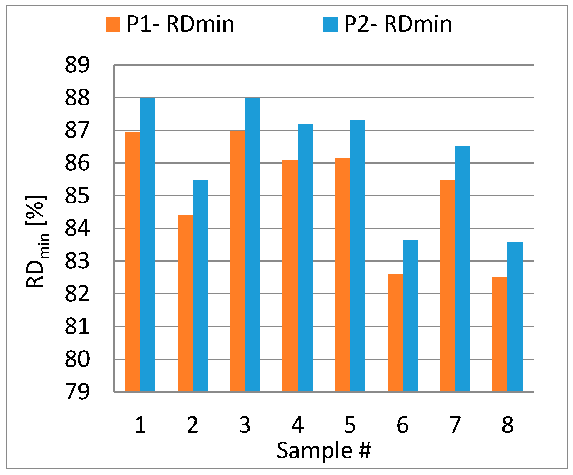
The minimum relative densities (RDmin) are recorded for both P1 and P2 from simulation results and are presented in Figure 20. There is clearly a difference in the amount of predictions for RDmin between the samples of the simulations.
In Figure 20, the results of #1 and #2 show the influence of face width on the RDmin values. While the normal module and the number of teeth are kept constant in both gears, it is observed that lower face-width will result in higher RDmin values compared with the increased face-width of sample #2. The same trend is observed from comparing the results of sample #3 and #4. The difference is that in sample #3 and #4, the normal module is increased and the number of teeth is decreased to keep the addendum diameter equal to the addendum diameter of samples #1 and #2. This geometrical change shows a slight improvement in RDmin, specifically if we compare the results of case #2 and #4 together this effect is very clear. In samples #2 and #4, the addendum diameter and face-width is equal but there is a noticeable difference in the RDmin generated after P1 and P2. This observation could support the theory that for larger face-widths, it is more favorable to design the gears with larger normal modules to increase the RDmin values.
Samples #5 and #6 are designed based on smaller addendum diameter compared to samples #1–#4. In these samples the results suggest that with a constant normal module and number of teeth it is expected to reach higher RDmin values when the face-width is lower as it is shown in Figure 20.
Comparing the results of all the sample from #1 to #6 supports the hypothesis that having a larger diameter at constant face-width in the gear geometry could influence the process to reach higher RDmin values. This could be seen by comparing #1, #3, and #5 separately as well as comparing #2, #4, and #6 with each other, as shown by Figure 20.
Samples #7 and #8 are designed with even smaller addendum diameters. In these two simulations, as is shown by Figure 20, the resulted RDmin is lower than samples #5 and #6. This set of simulation results also suggests the hypothesis that at a constant module and face-width, a larger addendum diameter, which is due to more number of teeth, could have an influence on the RDmin values. This could be observed from a pairwise comparison of samples #5 and #7, as well as pairwise comparison of samples #6 and #8.
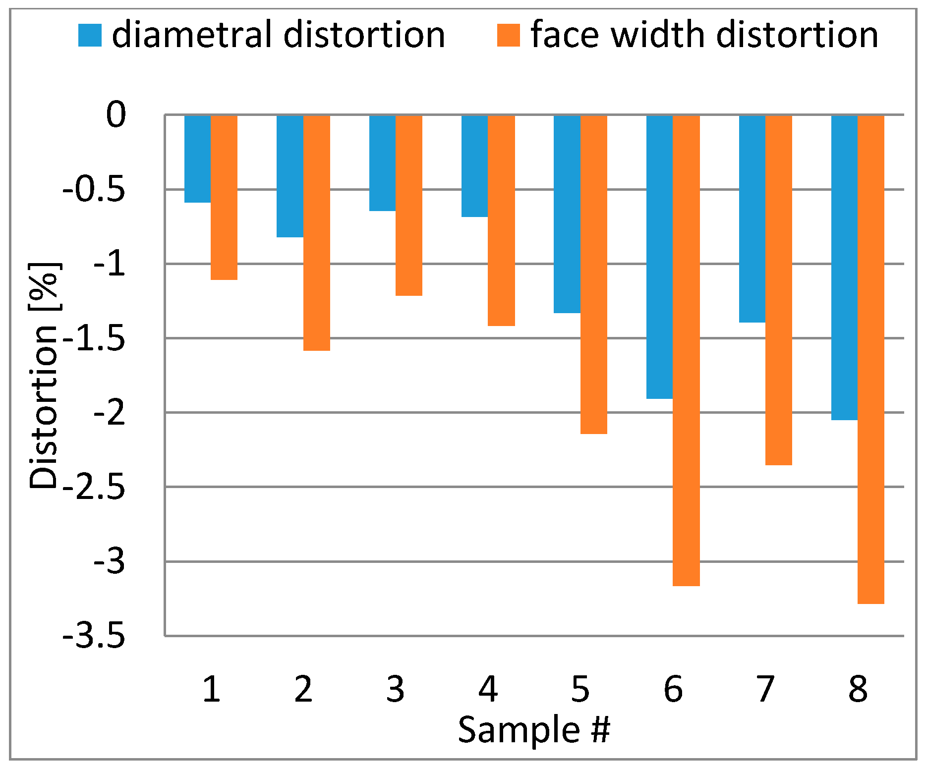
The results of distortions in the gear with respect to the gear addendum diameter and its face width are presented in Figure 21. From the results presented in Figure 20, to confirm the hypothesis presented earlier, it is expected that samples #1 and #3 show the lowest distortions caused by HIP since they have higher RDmin values after P2. As well, it is expected the highest amount of distortions will be observed in samples #6 and #8.
Distortions are defined here as the changes of the gear addendum diameter during the HIP and the changes of gear face width during the HIP. The values of distortions are measured from the results of the numerical simulations for all the eight sample gear geometries and are visualized in Figure 21.
The results shown in Figure 21 confirm that there should be a strong relation between the RDmin value created in pressing and the caused distortions by HIP. For the gears with highest RDmin, as in samples #1 and #3, the predicted distortions are the lowest. At the same time, it is predicted by the numerical simulation model that the gears that have lowest RDmin values will experience the largest distortions during HIP among the simulated samples of this study. The trends in the results that are illustrated in Figure 21 confirm that the geometrical parameters of the gears, which define the gear dimensions, are effective when it comes to manufacturing the gear using the investigated PM processing route in this work. This fact dictates that for reaching the full density using the HIP process after two times pressing and two times sintering stages, it is necessary to reach some critical RDmin to ensure that the distortions caused by HIP, and due to the un-avoidable density gradient in the PM components, are not out of the design limits for the post processing of the gears. The post processing of the gear could become very expensive if large distortions occur in the PM processing, which will increase the material waste as well as the cost of manufacturing.

5. Discussion

Let us take the results of the previous section and discuss a prediction model to estimate RDmin based on the gear parameters. Such a model could be used in practice for the selection of the most suited gear geometries for the present PM route. This should be combined with expertise and knowledge on gear post processing to define acceptable levels of distortion, which could be compensated in post processing but is not in the scope of this work.
For our purpose a correlation analysis is performed to confirm the connection between distortions for samples and their RDmin values after P2. The Pearson correlation coefficient of 0.84 is calculated for the correlation between the distortions of the addendum diameter and RDmin. Also, a Pearson correlation value of 0.87 is calculated for the correlation between the distortions of face-width and RDmin. These two coefficient values, supports the assumption that the RDmin value in the gear achieved during two times pressing and two times sintering steps of the route could be a proper indicator for the prediction of distortions caused by HIP as the last step of the route.
This has led us to construct predictive models for RDmin as a tool for estimating the influence of gear parameters that define the size of the geometrical distortions caused during HIP. This is performed using a simple linear regression analysis with three independent variables (mn, b, Z) and one dependent variable (RDmin) for P2. The resulting P-values for Z is 0.551, which suggests that Z is not statistically significant on the RDmin after P2. Therefore, the second analysis is performed and the results are shown in Table 4 for P2.
An examination of Table 4 makes it clear that both of the two geometrical parameters (mn, b) in the standard model are significantly predictive of the RDmin according to the ANOVA statistics [F (2, 5) = 20.105, p < 0.004]. Following the standard regression analysis, the model’s degree of predicting the dependent variable is R = 0.94. The model’s degree of explaining the variance in the dependent variable is R2 = 0.88. With these coefficients, it may be said that the model predicts the RDmin after P2 well. Based on the regression analysis results, the regression equation for prediction of RDmin after P2 is as Equation (2):
R D m i n ,   P 2 = 86.413 + 1.184 × m n 0.225 × b

6. Conclusions

In this paper, we have considered a powder processing route consisting of five steps to manufacture gears from a metal powder. The powder is processed through two times pressing and two times sintering to finally reach the full density, where a hot iso-static pressing of the component is done. The paper aim was to answer two main research questions. The first is to find out the potential relation between the distortions caused by HIP and the lowest relative density in the gear neutral zone (RDmin). The hypothesis was that the distortion driver is the density gradient caused in pressing and the amount of distortion could be different for different RDmin values. This was validated by the results presented in this work. This finding brought us to the second research question on how the RDmin could be affected by the gear dimensions. The hypothesis was that with a similar process condition and a certain material, the geometry of the gear could be decisive in the RDmin values generated by the pressing processes, which consequently could affect the HIP distortions. This hypothesis is also accepted and shown to be true by results presented from our simulations and experiments.
Answering the research questions enabled us to present a predictive model for RDmin based on the geometrical parameters of the gears in the pressing steps of the PM route. This was delivered using the data from an experimentally validated numerical simulation of the processes involved in the PM route. The predictive model is created by using linear regression analysis. Such a predictive model for RDmin could be useful to have an estimation about the process outcome before going into costly experiences. For this purpose, a linear regression analysis has been performed using the data from the results of eight samples to create a predictive model for RDmin after P2.
To implement the findings into practice for gear manufacturing using PM, the findings of this paper imply that for a specific group of gear geometries (with a certain combination of gear parameters) it is easier to process and manufacture the PM gear with lower distortions after HIP. This means such geometries will require less post processing (a finishing application such as grinding) to reach the final gear geometry after HIP. At the same time there is a group of gears that might show larger distortions during HIP because of the geometrical parameter influence. This means they will require higher amounts of finishing post processes after HIP, which is expensive and should be avoided to keep the manufacturing economically comparable with traditional methods. The reason is that in the case of a larger distortion, it would be necessary to add more stock on the component design so it might be possible to reach accurate tolerances after finishing. This finding will allow us to wisely choose which geometries are proper for being considered to be manufactured using the PM route investigated in this work. The regression model predicts that in general, larger normal modules and lower face widths are more suitable to reach higher levels of RDmin in the neutral zone of the PM gear, which could cause less distortions.
Considering the application of the process for manufacturing the gears, the results are very dependent on the gear parameters. For gears with larger normal modules (4–6 mm), which are common for gears in heavy vehicles, we can recommend the presented process route to be used when the gear face-width is not higher than 20 mm.

Author Contributions

Conceptualization, A.K.; Methodology, A.K.; Software, A.K.; Validation, A.K. and A.M.; Formal Analysis, A.K.; Investigation, A.K.; Resources, A.M.; Data Curation, A.K.; Writing—Original Draft Preparation, A.K.; Writing—Review & Editing, A.M.; Visualization, A.K.; Supervision, A.M.; Project Administration, A.M.; Funding Acquisition, A.M.

Funding

This research was funded by Swedish Governmental National Funding Agency VINNOVA grant number [2013-05594].

Acknowledgments

The authors would like to express their gratitude to Michael Andersson, Höganäs AB for his collaboration in running the experimental test and material verifications as well as his continued support during the research by providing insightful comments and feedback on the results. Also, we would like to thank Maheswaran Vattur from the Chalmers University of technology for performing the experimental measurements and his time for fruitful discussions during the project.

Conflicts of Interest

The authors declare no conflict of interest. The funders had no role in the design of the study; in the collection, analyses, or interpretation of data; in the writing of the manuscript, and in the decision to publish the results.

References

  1. Flodin, A.; Karlsson, P. Automotive transmission design using full potential of powder metal. In Proceedings of the PM2012, Yokohama, Japan, 14–18 October 2012; pp. 15–18. [Google Scholar]
  2. Capus, J. Industry Roadmap update from MPIF. Met. Powder Rep. 2012, 67, 10–11. [Google Scholar] [CrossRef]
  3. Capus, J.M. Surface-densified PM gears: New hope in new transmissions. Met. Powder Rep. 2006, 61, 18–21. [Google Scholar] [CrossRef]
  4. Cedergren, J.; Melin, S.; Lidström, P. Numerical investigation of Powder Metallurgy manufactured gear wheels subjected to fatigue loading. Powder Technol. 2005, 160, 161–169. [Google Scholar] [CrossRef]
  5. Glodež, S.; Šori, M. Bending Fatigue Analysis of PM Gears. Key Eng. Mater. 2017, 754, 299–302. [Google Scholar] [CrossRef]
  6. Klocke, F.; Gorgels, C.; Kauffmann, P. Challenges of Surface Densification of PM Gears by Rolling. In Advances in Powder Metallurgy and Particulate Materials, Proceedings of the 2008 World Congress on Powder Metallurgy & Particulate Materials, Washington, DC, USA, 8–12 June 2008; Metal Powder Industries Federation: Princeton, NJ, USA, 2008. [Google Scholar]
  7. Klocke, F.; Gorgels, C.; Kauffmann, P.; Gräser, E. Influencing Densification of PM Gears. In Future Trends in Production Engineering; Springer: Berlin/Heidelberg, Germany, 2013. [Google Scholar]
  8. Klocke, F.; Schröder, T.; Kauffmann, P. Fundamental study of surface densification of PM gears by rolling using FE analysis. Prod. Eng. 2007, 1, 113–120. [Google Scholar] [CrossRef]
  9. Strondl, A.; Khodaee, A.; Sundaram, M.V.; Andersson, M.; Melander, A.; Heikkilä, I.; Miedzinski, A.; Nyborg, L.; Ahlfors, M. Innovative Powder Based Manufacturing of High Performance Gears. In Proceedings of the European PM Conference Proceedings, European Congress and Exhibition on Powder Metallurgy, Hamburg, Germany, 9–13 October 2016; The European Powder Metallurgy Association: Shrewsbury, UK, 2016; pp. 1–6. [Google Scholar]
  10. Flodin, A.; Andersson, M.; Miedzinski, A. Full density powder metal components through Hot Isostatic Pressing. Met. Powder Rep. 2017, 72, 107–110. [Google Scholar] [CrossRef]
  11. Sundaram, M.V. Processing Methods for Reaching Full Density Powder Metallurgical Materials. Ph.D. Thesis, Chalmers University of Technology, Gothenburg, Sweden, 2017. [Google Scholar]
  12. ElRakayby, H.; Kim, H.; Hong, S.; Kim, K. An investigation of densification behavior of nickel alloy powder during hot isostatic pressing. Adv. Powder Technol. 2015, 26, 1314–1318. [Google Scholar] [CrossRef]
  13. Van Nguyen, C.; Bezold, A.; Broeckmann, C. Anisotropic shrinkage during hip of encapsulated powder. J. Mater. Process. Technol. 2015, 226, 134–145. [Google Scholar] [CrossRef]
  14. Van Nguyen, C.; Deng, Y.; Bezold, A.; Broeckmann, C. A combined model to simulate the powder densification and shape changes during hot isostatic pressing. Comput. Methods Appl. Mech. Eng. 2017, 315, 302–315. [Google Scholar] [CrossRef]
  15. Khodaee, A.; Melander, A. Evaluation of effects of geometrical parameters on density distribution in compaction of PM gears. In Proceedings of the 20th International ESAFORM Conference on Material Forming (ESAFORM 2017), Dublin, Ireland, 26–28 April 2017; American Institute of Physics (AIP): College Park, MD, USA, 2017. [Google Scholar]
  16. Höganäs, A.B. Material and Powder Properties Handbook. 2018. Available online: https://www.hoganas.com/globalassets/uploaded-files/handbooks/handbook-1-material_and_powder_properties_december_2013_0674hog-interactive.pdf (accessed on 3 July 2018).
  17. Dlapka, M.; Danninger, H.; Gierl, C.; Lindqvist, B. Defining the pores in PM components. Met. Powder Rep. 2010, 65, 30–33. [Google Scholar] [CrossRef]
  18. Essa, K.; Jamshidi, P.; Zou, J.; Attallah, M.M.; Hassanin, H. Porosity control in 316L stainless steel using cold and hot isostatic pressing. Mater. Des. 2018, 138, 21–29. [Google Scholar] [CrossRef]
  19. ABAQUS. ABAQUS Documentation; Dassault Systèmes: Providence, RI, USA, 2011. [Google Scholar]
  20. Drucker, D.C.; Prager, W. Soil mechanics and plastic analysis or limit design. Q. Appl. Math. 1952, 10, 157–165. [Google Scholar] [CrossRef] [Green Version]
  21. Wagle, G.S. Die Compaction Simulation: Simplifying the Application of a Complex Constitutive Model Using Numerical and Physical Experiments. Ph.D. Thesis, The Pennsylvania State University, State College, PA, USA, 2006. [Google Scholar]
  22. Gurson, A.L. Continuum theory of ductile rupture by void nucleation and growth: Part I—Yield criteria and flow rules for porous ductile media. J. Eng. Mater. Technol. 1977, 99, 2–15. [Google Scholar] [CrossRef]
  23. Bourih, A.; Kaddouri, W.; Kanit, T.; Madani, S.; Imad, A. Effective yield surface of porous media with random overlapping identical spherical voids. J. Mater. Res. Technol. 2018, 7, 103–117. [Google Scholar] [CrossRef]
  24. Slimane, A.; Bouchouicha, B.; Benguediab, M.; Slimane, S.A. Parametric study of the ductile damage by the Gurson–Tvergaard–Needleman model of structures in carbon steel A48-AP. J. Mater. Res. Technol. 2015, 4, 217–223. [Google Scholar] [CrossRef]
  25. Cochran, W.G.; Cox, G.M. Experimental Designs; Willey and Sons: Hoboken, NJ, USA, 1950. [Google Scholar]
Figure 1. Process route to reach full density in powder metallurgical (PM) gears [9].
Jmmp 02 00049 g001
Figure 2. The generation of neutral zone with lower relative density (RD) at the middle of face width of the gear.
Jmmp 02 00049 g002
Figure 3. (a) The gear specification for the experiments; (b) Major dimensions of the gear considered in the analysis.
Jmmp 02 00049 g003
Figure 4. (a) The ring specimen dimensions used for the compaction test; (b) The simulation model for the compaction test; (c) The powder deformation and simulation of the compacted ring from the loose powder; (d) The fitted hardening curve for the displacement-force of powder.
Jmmp 02 00049 g004
Figure 5. (a) First pressing simulation model; (b) Second pressing simulation model; (c) HIP Boundary conditions for the simulation model.
Jmmp 02 00049 g005
Figure 6. Gear I: The average density growth (ρave).
Jmmp 02 00049 g006
Figure 7. Gear II: The average density growth (ρave).
Jmmp 02 00049 g007
Figure 8. Gear I, relative density (RD) after P1.
Jmmp 02 00049 g008
Figure 9. Gear II, relative density (RD) after P1.
Jmmp 02 00049 g009
Figure 10. Gear I, relative density (RD) after P2.
Jmmp 02 00049 g010
Figure 11. Gear II, relative density (RD) after P2.
Jmmp 02 00049 g011
Figure 12. Gear I, relative density (RD) after HIP.
Jmmp 02 00049 g012
Figure 13. Gear II, relative density (RD) after HIP.
Jmmp 02 00049 g013
Figure 14. The addendum diameter after P1, P2, and HIP from Gear I experiments and simulations.
Jmmp 02 00049 g014
Figure 15. The addendum diameter after P1, P2, and HIP from Gear II experiments and simulations.
Jmmp 02 00049 g015
Figure 16. Face width (b) after P1, P2, and HIP from Gear I experiments and simulations.
Jmmp 02 00049 g016
Figure 17. Face width (b) after P1, P2, and HIP from Gear II experiments and simulations.
Jmmp 02 00049 g017
Figure 18. Mean squared of errors (MSE) percentage as comparison of simulation and experimental results for Gear I & II; (a) MSE for average density; (b) MSE for face width; (c) MSE for addendum diameter.
Jmmp 02 00049 g018
Figure 19. Eight selected gear parameters for further analysis on the influence of gear size on the PM processing.
Jmmp 02 00049 g019
Figure 20. RDmin for simulations of eight samples from simulations #1–8.
Jmmp 02 00049 g020
Figure 21. Maximum distortions in form of shrinkage in gears in simulations #1–8.
Jmmp 02 00049 g021
Table 1. Modified Drucker Prager model CAP plasticity parameters in ABAQUS for the simulation of P1.
Material Cohesion [MPa]Angle of Friction [°]Cap Eccentricity [-]Initial Yield Surface Position [MPa]Transition Surface Radius [-]Flow Stress Ratio [-]
0.05970.550.50.010.011
Table 2. Gurson plasticity parameters in ABAQUS for simulation of P2 and Hot Iso-static Pressing (HIP).
q1 [-]q2 [-]q3 [-]
111
Table 3. Linear modification factors for S1 and S2.
ProcessModification Factor [%]
S1−0.69
S2+0.50
Table 4. Results of ANOVA [25] for eight different samples simulation results from P2 without considering Z as a parameter.
CoefficientsStandard Errort Statp-ValueLower 95%Upper 95%
Intercept86.4311.11577.4970.00083.56489.298
b−0.2250.045−4.9580.004−0.342−0.108
mn1.1840.3003.9530.0110.4141.954