Article

Improvement of Numerical Modelling Considering Plane Strain Material Characterization with an Elliptic Hydraulic Bulge Test

Institute of Manufacturing Technology, 91058 Erlangen, Germany
*
Author to whom correspondence should be addressed.
J. Manuf. Mater. Process. 2018, 2(1), 6; https://doi.org/10.3390/jmmp2010006
Submission received: 22 December 2017 / Revised: 9 January 2018 / Accepted: 11 January 2018 / Published: 16 January 2018
(This article belongs to the Special Issue Analysis and Modeling of Sheet Metal Forming Processes)

Abstract

:
A precise characterization of material behavior is necessary to identify yield criteria or hardening laws for an accurate numerical design of sheet metal forming processes. Current models like Yld2000-2d or Hill’48 do not consider the plane strain state, though this condition is primary cause of failure in deep drawing. It is anticipated that an improved yield locus contour which considers the stress under plane strain conditions leads to better results in numerical simulations of a deep drawing process. Within this contribution, a new experimental setup to characterize both principal stress components under plane strain as additional input data for material modelling is presented. Therefore, hydraulic bulge tests are carried out with a novel elliptical die, which implements a plane strain condition. Moreover, the improvement of the material model is investigated exemplarily for the three sheet metal alloys DC06, DP600 and AA5182. The resulting material parameters are used to identify the yield locus for plane strain by varying the yield locus exponent of Yld2000-2d. The results prove that considering plane strain yield locus results in a better sheet thickness distribution in comparison to conventional modelling of the deep drawing process.

1. Introduction

In many branches of industry, there is a trend towards a reduction of the overall weight through a lightweight construction concept. In order to achieve this, a central aspect is an increase in efficiency of material utilization in deep drawn products. Components made of conventional materials with a high sheet thickness are substituted by high-strength materials with a lower thickness and, therefore, a lower weight or materials with a lower relative density. The challenge in this context is the lower formability of these materials. The applicability of these alloys increases with the use of modern software, which can digitally map the forming process.
Therefore, the material data is an essential input for numerical process design and, thus, for the quality of the simulation results [1]. Hence, the stress state at plane strain is of crucial importance, since there is a low formability and a strong sheet thinning occurs even at low degrees of deformation [2]. This low formability can be explained by the material flow, that is present exclusively in the sheet thickness direction as a result of the flow restriction in the minor strain. As a result, in the automotive sector, over 80% of failure within the forming operation is caused under plane strain or near plane strain [3]. In conventional yield criteria, such as, Yld2000-2d [4], the plastic material behavior in the region of plane strain is described indirectly by a fit between the uniaxial tensile stress and the equi-biaxial stress state. A direct determination under plane strain conditions is not required for this model. Both aspects, the lack of a direct determination of the flow stress in combination with the high error rate at plane strain implies an enormous potential for improving the mapping accuracy of numerical designed forming operations.
For a characterization of the plane strain material behavior, notched tensile tests are carried out. These experiments are mainly used to determine the forming limit curve (FLC) under plane strain conditions instead of the otherwise performed Nakajima tests [3]. By using optical strain measurement technology, locally resolved strain fields can be determined in tensile test specimens in order to characterize the local material behavior. The determination of the resulting stress components out of the strain data is not possible in the case of notched tensile tests, since the force measurement in the transverse direction, which means ε2 = 0 is not possible. Flores et al. [5] and Wagoner [6] came up against this challenge by defining a dependence of the two principal stresses with the material anisotropy that is quantified in uniaxial tensile tests. Wagoner referred to the mean vertical anisotropy which can be ascribed to the theory of Hill [4] with a factor m = 2. In contrast to this, Flores et al. described a relationship to the material anisotropy in transverse direction. Furthermore, for the model of Flores et al., a maximum tolerable transverse contraction of 0.02 true strain was assumed. Within this boundary, the area under plane strain conditions could be determined for each time step. Investigations by Kuwabara [7] with a modified cruciform tensile test proved that the relationship of the second principal stress to the material anisotropy overestimates this stress component and leads to a higher stress.
Another innovative method, which is mainly used for the determination of forming limit curves with positive major and minor strain, is the hydraulic bulge test (HBT) with elliptical dies with a differing ratio of the two radii. Hecht [8] applied this setup to determine plastic formability of magnesium even at elevated temperatures. For the characterization of the material anisotropy, Altan et al. [9] utilized elliptical dies to determine the planar anisotropy. A fundamental study of the plastic material behavior in hydraulic bulge tests with elliptical dies was given by Rees [10]. To determine the flow stress at the pole, Rees provided formulations for the principal stress components as a function of the material anisotropy. Lazarescu calculated the stress components from elliptical hydraulic bulge tests using the shell theory [11]. The dependence of the flow stress on the aspect ratio was investigated by Lazarescu in [12].
Derived from these approaches of material characterization using an elliptical bulge test, the potential to use the material data of the first and second principal stress for a subsequent modelling is obtained. An increasing complexity of the material model leads to a more accurate mapping of the real material behavior. The anisotropic yield criterion Yld2000-2d, for example, requires eight experimental parameters to determine the eight model parameters. The identification with additional material data leads to an over-determination of the equation system. Hence, there are various possibilities to use additional material data. Investigations have shown that the real material hardening behavior is not equal for all stress states (isotropic hardening), but is stress-state-dependent [13]. This distortional hardening leads to a change of the yield locus geometry and varies over the true plastic strain. Considering this in numerical mapping, non-associated flow rules are used. These are based on a yield criterion, which is, however, newly identified as a function of the true plastic strain. In contrast to the non-associated flow rule, an associated flow rule is expanded isotopically. Safei et al. [14] used a non-associated flow rule based on Yld2000-2d to map the distortional hardening behavior with a strain dependent modelling of the eight parameters with polynomial functions. A further approach utilized the yield locus exponent m in the yield criterion Yld2000-2d in order to be able to vary the geometry of the yield locus over the plasticization [15]. Zang et al. [
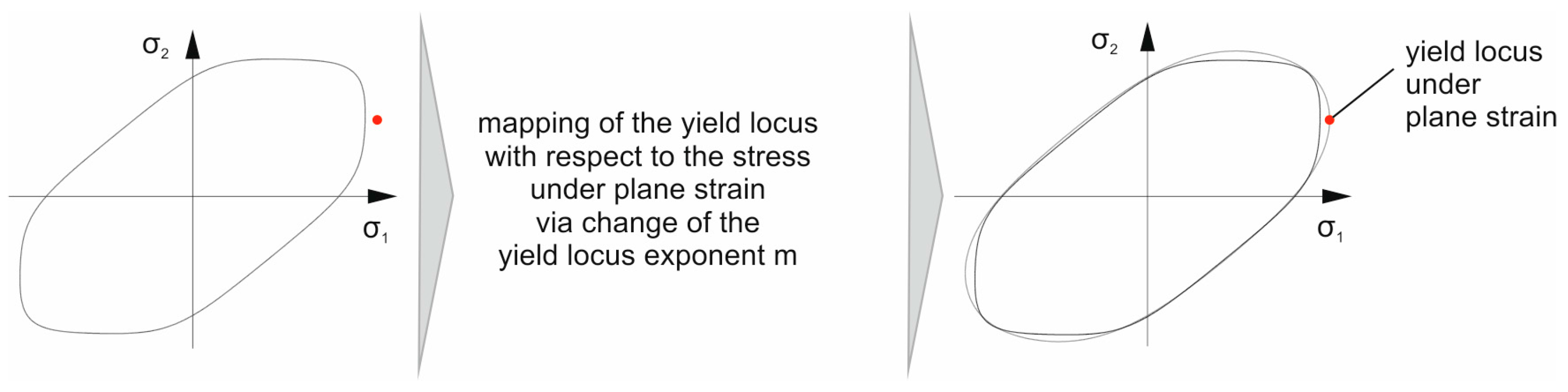
16] performed linear transformations to vary the yield locus geometry. A disadvantage of these approaches with non-associated flow rules is a higher numerical effort by the required subroutine, which depicts the material behavior as a function of the degree of plastic strain. In contrast to this, an integration of additional material information can be achieved via the yield locus exponent m. Since the yield locus exponent is a mathematical expression for the model and has no metallophysical basis, state of the art is a choice of the yield locus exponent m of the phenomenological yield criterion Yld2000-2d depending on the material class. This selection of the exponent has a decisive influence on the resulting geometry of the yield locus. Usually, this parameter is given by m = 6 for body centered cubic materials (bcc) and m = 8 for face centered cubic materials (fcc) [2]. In contrast to this, Plunkett et al. [17] defined the yield locus exponent with m = 5 for bcc materials. However, these recommendations have no basis in metal plasticity. The choice of the yield locus exponent defines the geometry in the area between uniaxial and equi-biaxial stress as well as the area of shear stress. Considering this, an integration of additional material information in the associated flow rule Yld2000-2d can be done by an experimentally supported selection of the yield locus exponent m. Investigations by Kuwabara [18] and Merklein [19] have shown that the stress-state-dependent material behavior can be modelled by the use of a strain-dependent variation of the yield locus exponent.
Due to the relevance of the plane strain state regarding failure and the missing of a robust testing setup to characterize this strain state, there is demand for integrating this in numerical models. The only well described testing setup is the notched tensile test, with the disadvantage of no possibility to determine the second principal stress. Within this contribution, an experimental setup for the characterization of both principal stress components under plane strain conditions is introduced. Therefore, a hydraulic bulge test with an elliptical die is used to calculate the resulting stress out of the time dependent strain data and geometry. Furthermore, the additional material data is used to improve the yield criterion Yld2000-2d. In state of the art material modelling of Yld2000-2d, the material dependent yield locus exponent m is chosen according to the lattice structure. But for this hypothesis, there is no metal physical basis. Therefore, this contribution presents a new method to determine the yield locus exponent with experimental data. The simulation of a cruciform cup in comparison to experiments reveals the enhancement of the material model considering the sheet thickness distribution in the areas of plane strain.

2. Experimental Setup and Methodology

2.1. Materials and Specimen Preparation

For the investigation, the three commonly used materials AA5182-O, DC06 and DP600 are used. The natural hard aluminum alloy AA5182 is characterized by a high strength and a good formability. Because of an excellent corrosion resistance and weldability, this material is used for body parts in the automotive sector. The deep drawing steel grade DC06 for cold forming operations is characterized by a low yield strength and a high hardening exponent, which makes DC06 a suitable alloy for complex parts, like oil pans in the automotive industry. The high-strength dual phase steel DP600 is used in components in vibrating environments, such as for commercial vehicle wheels. A high basic strength, and at the same time a high forming and hardening capacity characterize this steel grade. The mechanical properties of all three alloys are shown in Table 1.
The sheet thickness of all alloys is t0 = 1.0 mm. The specimens used for the elliptical hydraulic bulge test are circular with a diameter of 395.0 mm. Two notches under 0° 45° and 90° according to rolling direction are used for identification purposes and for a robust alignment in the testing setup, respectively. All specimens are extracted by laser cutting (TruLaser Cell 7020, Trumpf GmbH + Co. KG, Ditzingen, Germany).

2.2. Methodology

2.2.1. Experimental Setup

The experimental setup, used within this contribution is based on the hydraulic bulge testing setup, introduced by Suttner and Merklein [20]. This testing setup in Figure 1 is integrated in a hydraulic press (HPDZb 630, Schuler Hydrap GmbH & Co. KG, Plüderhausen, Germany) with a maximum force of 6300 kN. The specimen is clamped between an upper and lower tool part with a clamping force of 3500 kN, which guarantees that no material flow from the flange area occurs. The die has a diameter of d1 = 200 mm and d2 = 75 mm with a die radius of 28 mm. The resulting aspect ratio is 2.67 for the ellipsoid. The introduced elliptical geometry is numerically optimized for failure under plane strain conditions in the center of the specimen and optimized to a reduced bending strain overlap which would reduce the formability and causes failure in the die radius. To measure the hydraulic pressure for the determination of the stress, a pressure sensor with 40 MPa is integrated. The local strain distribution during the forming process is detected by a three-dimensional optical strain measurement system (ARAMIS, GOM GmbH, Braunschweig, Germany) with a camera resolution of five megapixels. The testing device is able to perform material testing with a constant strain rate by controlling the forming speed during the test with the help of the optical measurement system. Therefore, the volume flow of the hydraulic medium is regulated with an online strain measurement. This information is used to control the speed of the hydraulic pressure transducer (Pregler GmbH Co. KG, Deggendorf, Germany).

2.2.2. Experimental Procedure

The investigation of the material behavior under plane strain conditions is done according to the DIN EN ISO 16808 for a circular bulge test. Tests are carried out in rolling direction (RD), diagonal direction (DD) and transversal direction (TD) for DC06 and AA5182-O to investigate the directional dependent material behavior. For the DP600, tests in rolling direction and transversal direction are performed. The adjusted strain rate is 0.4%/s for DC06 as well as DP600 and 0.667%/s for the aluminum. The testing velocity is in accordance with the national standard SEP1240 [21] for steel and VDA 239-300 [22] for aluminum and is also used for uniaxial tensile tests and circular hydraulic bulge tests. The elliptic hydraulic bulge tests are carried out until failure of the specimen, in order to quantify the maximum major and minor strain in the pole. Three tests are carried out for each parameter setup. For further investigation, the deformation field is measured with a 3D optical strain measurement device. Advantage of this measurement method is the possibility of a geometrical measurement of the specimen, and thereby the measurement of the time-dependent radii of the ellipsoid of revolution, as one can see in Figure 2. For further evaluation, the strain tensor in the center of the specimen is used. Due to the symmetrical structure, the specimen center is related to the pole of the formed dome. The relevant geometrical parameters are the radii of curvature in the center, which are described with a best fit cylinder in both directions, respectively. The determination of these cylinders is done in an evaluation area for the radius of curvature r1 of 30 mm in x direction and 5 mm in y direction. For the determination of the curvature r2 in y direction, an evaluation area of 30 mm in y direction and 5 mm in x direction are used. Figure 2 illustrates the evaluation areas for both curvatures.

2.2.3. Determination of Flow Curves under Plane Strain

With the resulting parameters of curvature r1 and r2, the pressure and the resulting total strain tensor in the pole center, the resulting principal stress components can be determined for each measured time increment in Equations (1) and (2) with the shell theory [23].
σ 1 ( t ) = p ( t ) · r 2 ( t ) 2 t ( t )
σ 2 ( t ) = p ( t ) · r 2 ( t ) 2 t ( t ) ( 2 r 2 ( t ) r 1 ( t ) )
In Equation (1), p(t) is the detected pressure, r2(t) is the determined radius and t(t) refers to the actual sheet thickness. The same counts for Equation (2). Here, additionally, the radius r1(t), which corresponds to the curvature in x direction, is needed. The sheet thickness in the pole can be calculated with the measured strain data (see Equation (3)).
t ( t ) = t 0 ε 3 , p l ( t )
For Equation (3), the initial sheet thickness t0 is needed. The true plastic strain in sheet thickness direction ε3,pl(t) is calculated in Equation (4).
ε 3 , p l ( t ) = ε 1 , p l ( t ) ε 2 , p l ( t )
Due to the volume consistency of the material under plastic deformation, Equation (4) can be solved with the true plastic strain components in x direction ε1,pl(t) and y direction ε2,pl(t). To determine the true plastic strain components, the elastic strain has to be reduced from the measured total strain in both directions. Therefore, the elastic strain in both principal directions has to be calculated, (see Equations (5) and (6)).
ε 1 , e l ( t ) = σ 1 ( t ) E ν σ 2 ( t ) E
ε 2 , e l ( t ) = ν σ 1 ( t ) E + σ 2 ( t ) E
For the elastic strain calculation in Equations (5) and (6), the material specific Young modulus E and because of the influence of σ1 to the elastic strain in ε2 direction and vice versa, the Poisson ratio ν is needed. The plastic strain ratio can be determined with Equations (7) and (8).
ε 1 , p l ( t ) = ε 1 , t o t a l ( t ) ε 1 , e l ( t )
ε 2 , p l ( t ) = ε 2 , t o t a l ( t ) ε 2 , e l ( t )
The total strain ε1,total and ε2,total in Equations (7) and (8) are measured with the optical strain measurement device.

2.2.4. Verification of the Proposed Approach

The calculated principal stresses are further used for an optimization of the yield criterion Yld2000-2d. Therefore, the yield locus exponent m is varied, in order to fit the curvature to the measured plane strain yield locus. For that purpose, the yield locus geometry is determined with the initial m value given in the literature. For improvement, the calculated root mean square error of the resulting yield locus under plane strain conditions in comparison with the experimental stress data is calculated. On this basis an optimization is done in order to minimize the resulting root mean square error between the plotted curve and the experimental principal stress components under plane strain conditions to a maximum residuum of 0.5 MPa. Therefore, the m value is changed by a step size of 0.01. The identified m value and the additional material data are used for numerical simulation of a cruciform cup. Furthermore, cruciform cups are deep drawn for all three materials. The resulting sheet thickness distribution in comparison to the numerically determined sheet thickness serves as validation of the optimized material data. The results of the optimization of the yield surface are shown in Chapter 5.
The experiments are performed with a hydraulic press (HPDZb 630, Hydrap) and a cruciform cup geometry. The used parameters are given in Table 2. The experiments are performed with lubricated blanks to guarantee defined tribological conditions. After the deep drawing process, the cups are digitalized with a stripe-light scanner. The result is a digital solid that can be compared to resulting geometries of the simulations. The finite element simulations are performed with a solver (LS-DYNA, Livermore Software Technology Corporation, Livermore, CA, USA). Therefore, the cruciform geometry was applied with shell elements and seven integration points over the sheet thickness.

3. Results of Plane Strain Hydraulic Bulge Tests

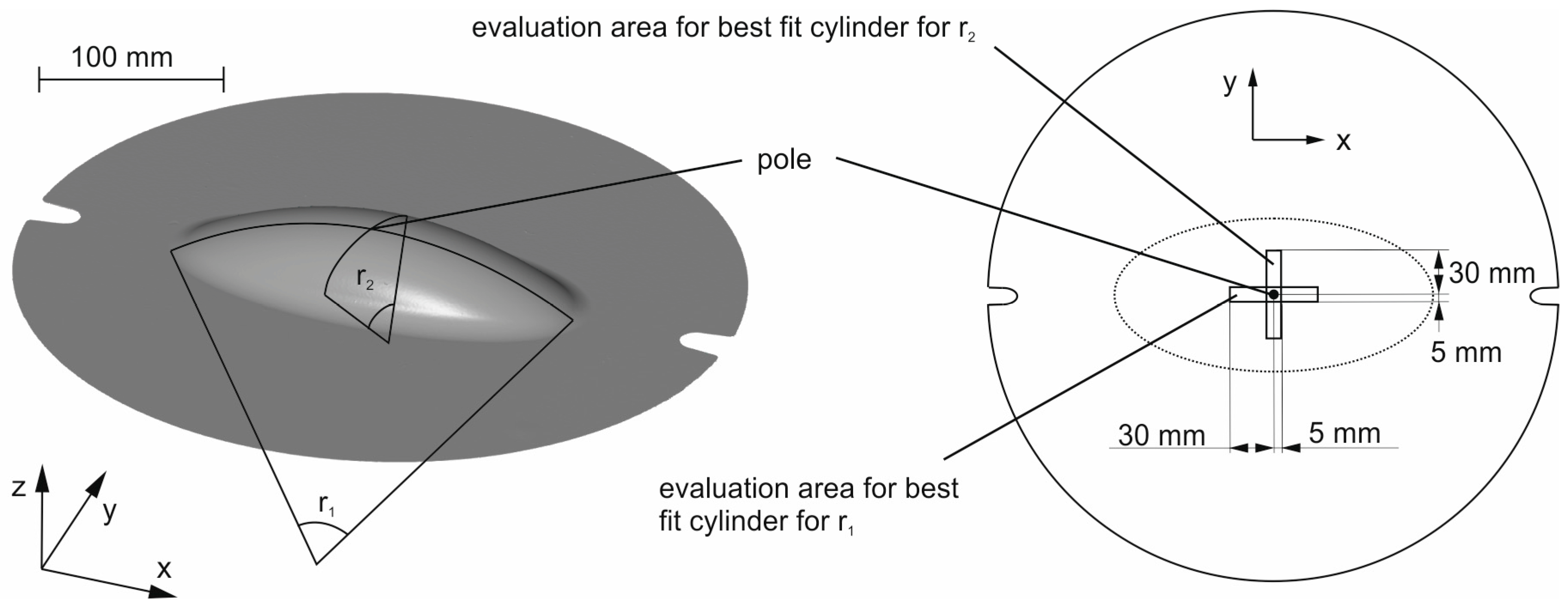
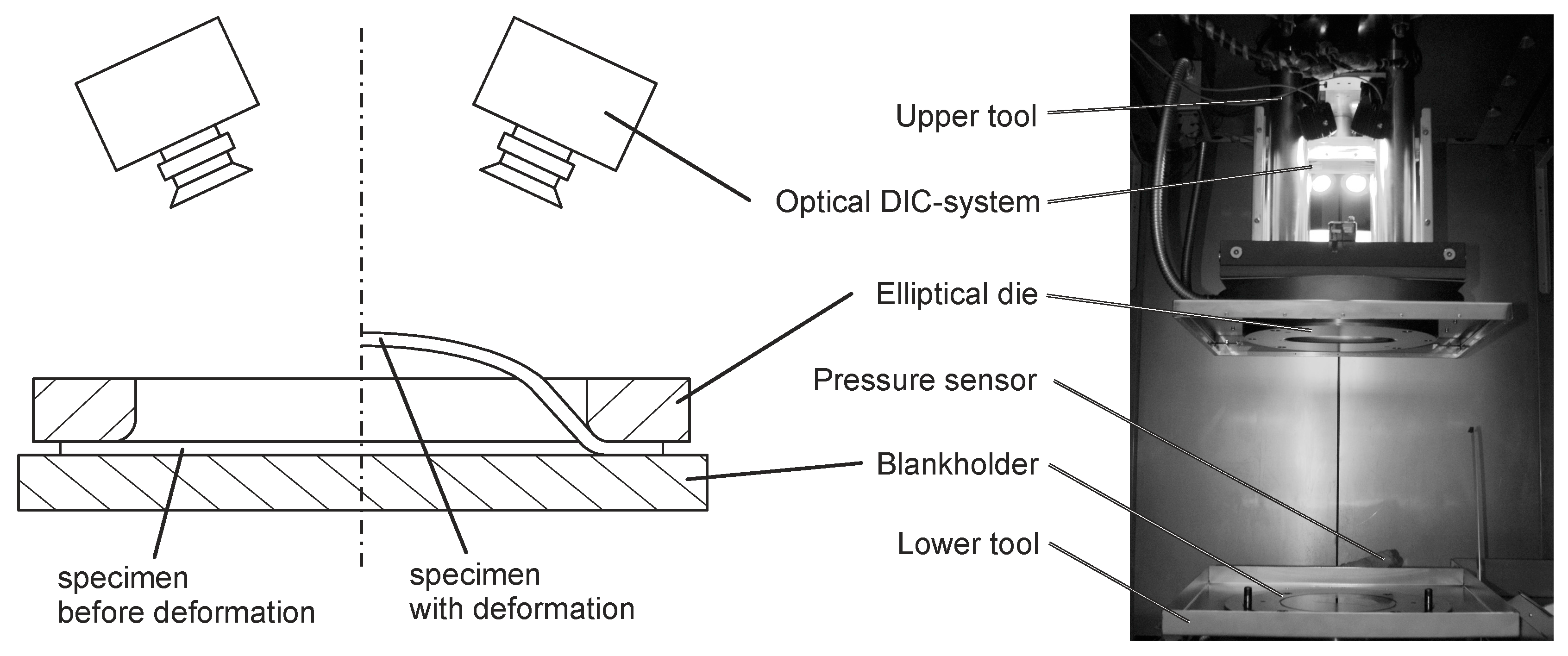
For material characterization, hydraulic bulge tests with an elliptic die geometry are performed. Therefore, specimens are clamped and formed with hydraulic pressure until failure. 
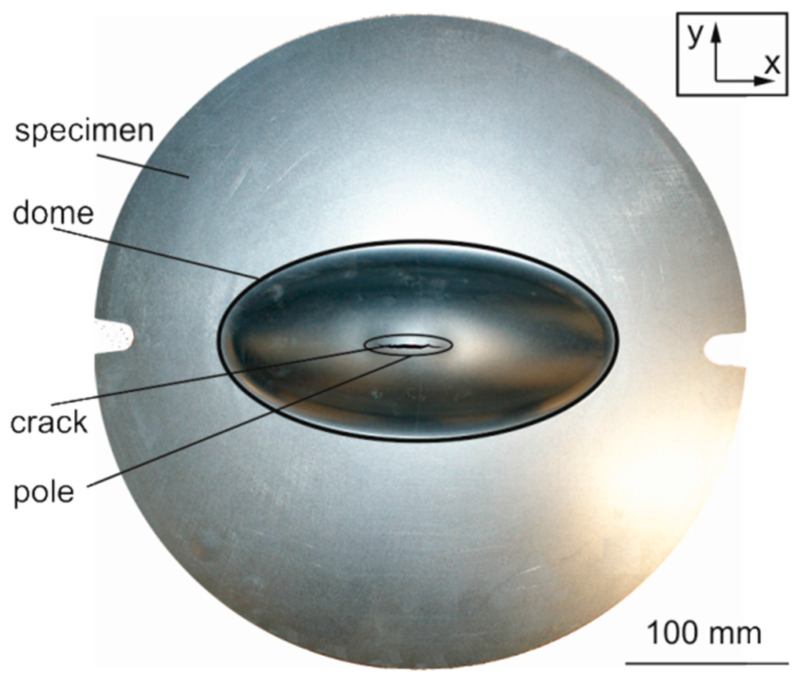
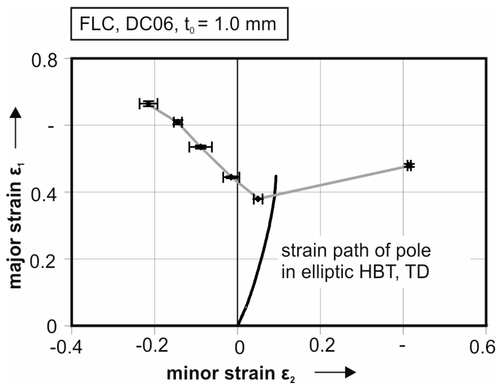
Figure 3 illustrates a tested specimen of DC06. A crack along the x direction at the pole of the formed dome is observable. Because of the highest strain in the pole, crack initiation starts at this point. This is an important aspect, because of the testing setup with the strain measurement system observes only the middle part of the specimen.
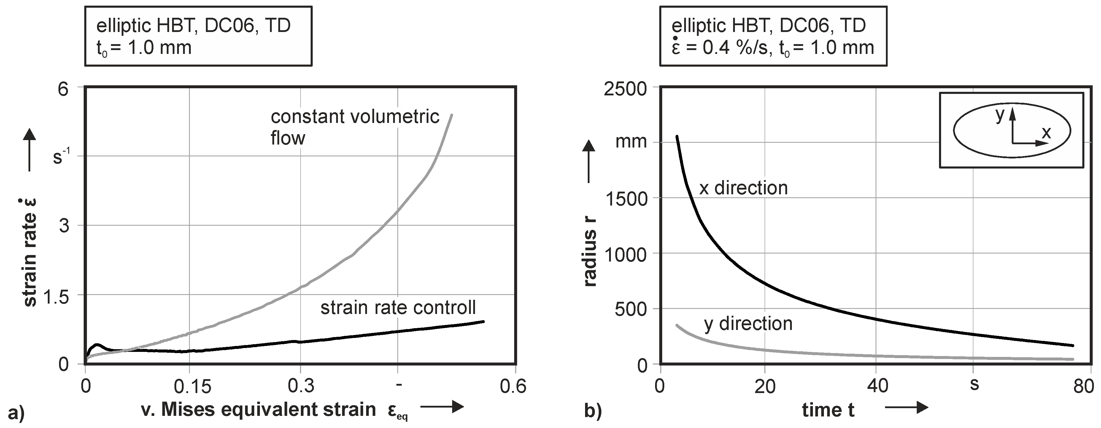
To guarantee a constant forming velocity, the resulting strain rate over the equivalent strain according to von Mises is illustrated in Figure 4a. For experiments with strain rate control and a target deformation velocity of 0.4%/s the resulting strain rate is drawn as a black line. In contrast to this, an experiment with constant volumetric flow is given (see grey line). For the beginning of plastic deformation, both testing setups give an accurate strain rate. With higher yielding, the exponential progression of the constant volumetric flow significant influences the measurement. At the point of cracking, the strain rate is more than ten times higher than the desired forming velocity. This would cause a wrong hardening characterization of strain rate sensitive materials. Also, the crack initiation starts at a lower equivalent strain. In the case of DC06, cracking starts at 0.55 von Mises equivalent strain for a strain rate controlled measurement, while crack initiation begins at 0.50 von Mises equivalent strain with a constant volumetric flow. For the strain rate controlled HBT, a small increase of the strain rate is also detectable. This increase is explained by localized necking of the specimen at high stains in the pole center, which leads to a local increase of the straining velocity.
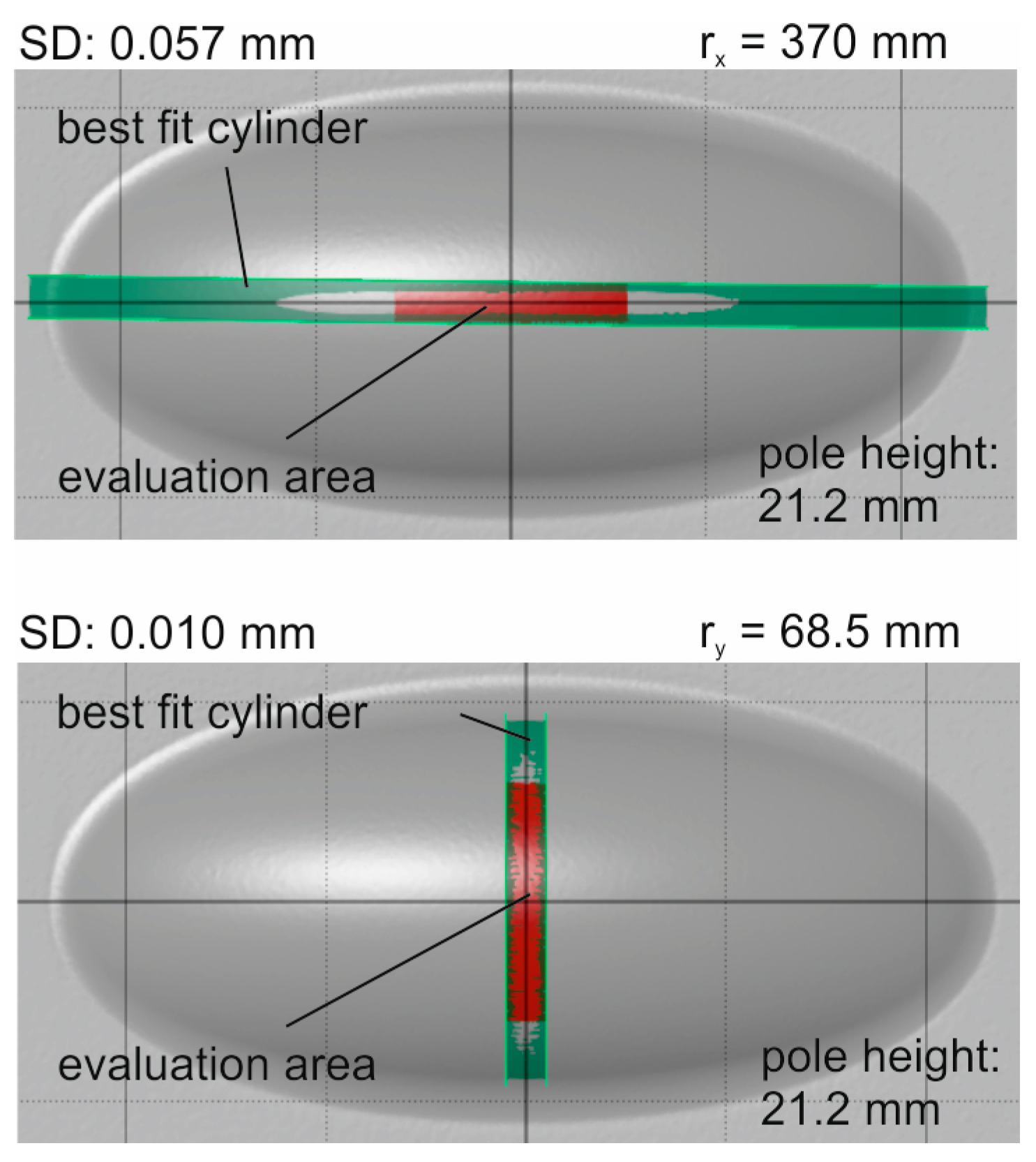
The resulting curvature of the specimen is depicted in Figure 4b for the DC06. Due to the 3D optical strain measurement system, the local strain distribution can be measured with additional information of the deformed coordinates of the measurement field. The curvature is measured with best fit cylinders for each time step in the particular directions separately. At the beginning of the test, the specimen shows no curvature at all. This leads to no information about curvature at the first seconds of the test. Afterwards, especially for the curvature in the x direction, the radius is about 2000 mm, which is very large and leads to a high standard deviation of 26.6 mm in the determined radius, because of the uncertainty of the measurement at the beginning. This leads to a standard deviation of the von Mises equivalent stress of 8.0 MPa at the onset of yielding. Besides the curvature in x direction, for the stress evaluation, the curvature in y direction is needed.
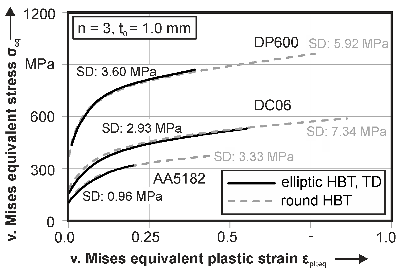
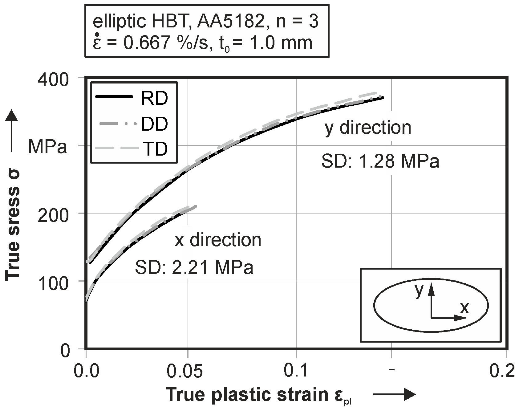
For the flow curve evaluation, three tests with identical parameter setups are performed. This evaluation of the resulting stress-strain curves of both principal stresses is done for all three materials according to the three investigated directions—rolling direction (RD) diagonal direction (DD) and transversal direction (TD). For the aluminum alloy in 
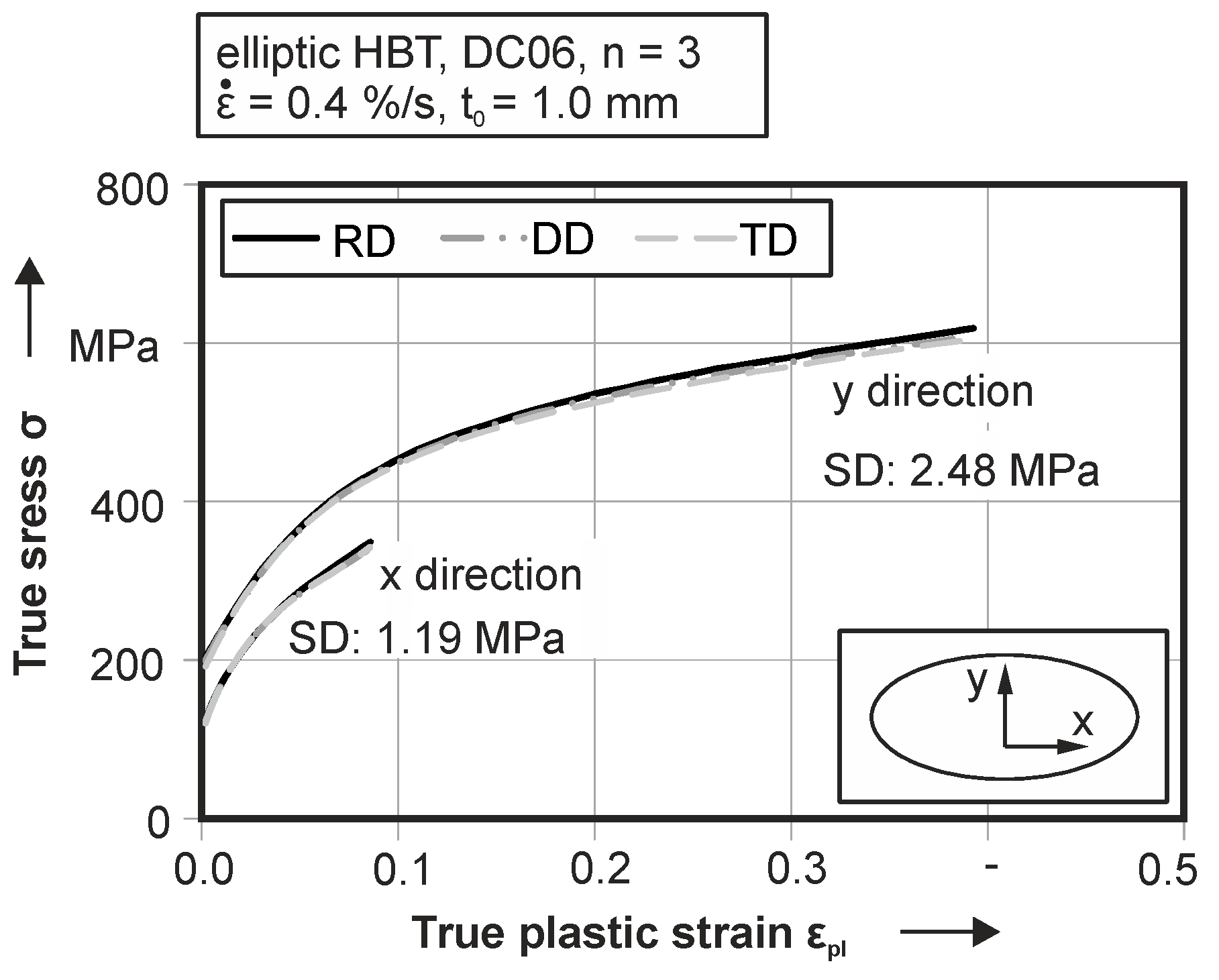
Figure 5, the analysis of the principal stress components in transversal direction show a slightly higher value than in rolling and diagonal directions. In general, the standard deviation is 1.28 MPa for the principal stress in the y direction and 2.21 MPa for the stress in the x direction. Expressed as a percentile, a standard deviation under 2% for the tests is measured. Therefore, the reproducibility is given for this testing setup. The maximum true plastic strain in x direction is on an equal level for all investigated directions and can be quantified as 0.053. In contrast to this, the true plastic strain in y direction is significantly higher and is 0.145 true plastic strain. In contrast to the aluminum, for the DC06, depicted in Figure 6, a higher plastic deformation in both principle directions is observable. Here, the onset of yielding is at 189.1 MPa true stress in transversal direction. Cracking is observable at a true plastic strain of 0.39 for the steel. Due to the work hardening, the flow stress before cracking is 597.5 MPa. The mean standard deviation of the flow stress is quantified as 2.48 MPa. For the stress component in x direction, there is a similar standard deviation SD = 1.19 MPa of the flow stress for experiments in TD. Plastic deformation begins in this case at 118.2 MPa true stress and increases to 349.6 MPa at a true plastic strain of 0.09. For the optimization of the yield locus geometry, both principal stress components are used. The second steel grade, the DP600 (see 
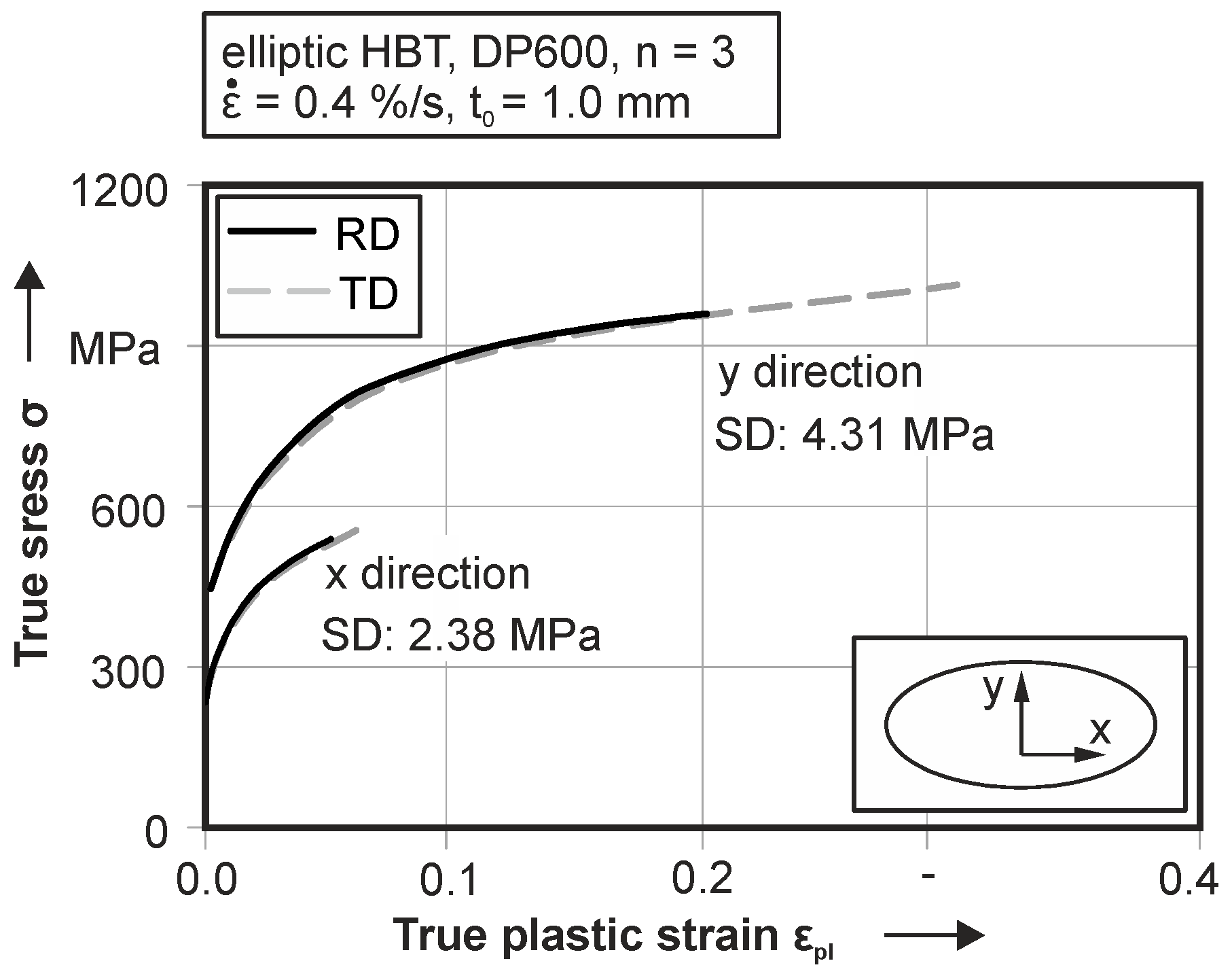
Figure 7) shows a significant directional dependent material behavior. Experimental results in rolling direction exhibits crack initiation at 0.2 for the y direction and 0.05 true plastic strain in x direction. For experiments in transversal direction, a significant higher formability is observable. The crack initiation starts at 0.3 true plastic strain in y direction and 0.065 in x direction. In contrast to the different straining behavior, the yield strength and the hardening is on equal level for both investigated directions. The mean standard deviation of the resulting flow curve is 4.31 MPa in y direction and 2.38 MPa in x direction.
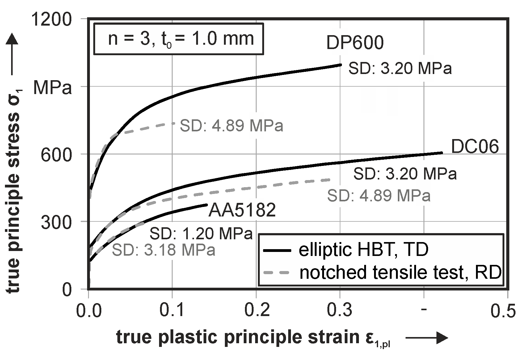
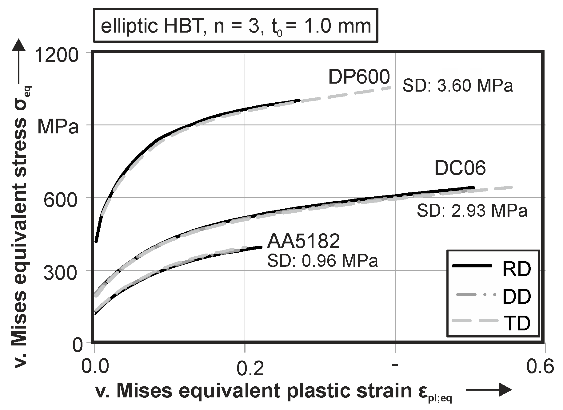
For a comparison with other stress and strain states, as well as for the parameter identification for the material model, a calculation of the von Mises equivalent stress and strain is done for all three materials, see Figure 8. Therefore, both principal stress components are used for the calculation. In case of the AA5182, the beginning of plastic deformation is visible at a true stress of 104.3 MPa in RD and 111.0 MPa in TD. Failure occurs at 0.22 equivalent plastic strain in rolling direction at an equivalent stress of 324.8 MPa. For DD and TD, crack initiation starts at 0.20 equivalent plastic strain with a true stress of 318.5 MPa in DD and 324.7 MPa in TD. The deep drawing steel DC06 inhibits a beginning of plastic deformation at 168.9 MPa in RD and 169.7 MPa in DD. In TD, the yielding starts at 159.4 MPa. The equivalent plastic strain at failure is 0.50 for RD and DD and 0.55 in TD. The resulting stress at ultimate elongation is 528.4 MPa in RD, 519.6 MPa in DD and 529.1 MPa in TD. It is remarkable that the ultimate elongation in rolling direction for the aluminum is higher than in the other directions. The same can be seen for the DC06 and the DP600, but for this alloy TD has the highest ultimate elongation. Plastic deformation of DP600 starts at a true stress of 345.9 MPa in rolling direction and 344.2 MPa in transversal direction. Failure of the specimen is observable at 825.9 MPa and a corresponding von Mises equivalent rue strain of 0.27 for RD. In orthogonal direction, cracking is visible at 0.39 equivalent true strain and an equivalent true stress of 869.1 MPa. In general, the standard deviation of the true stress curves in this testing setup is under 1.0%.

4. Process Verification and Validation

The presented testing setup for a material characterization under plane strain conditions has been proven on applicability. At first, the evaluation area is tested for applicability. The resulting strain of the specimen is then analyzed with regard to plane strain in Nakajima tests. Additionally, the resulting equivalent stress-strain curves are compared to the flow curve of circular HBT, because of the similar testing setup. A comparison to notched tensile tests is done, regarding the first principal stress progression in elliptic HBT and notched tensile tests.

4.1. Verification of the Evaluation Area for the Curvature Determination

The proposed area for the evaluation of the best fit cylinders has to be proven. Therefore, an elliptic hydraulic bulge test with DC06 is performed with testing parameters comparable to the test for material characterization and stopped at medium deformation. The resulting dome has a height of 21.1 mm. This specimen is scanned with a stripe-light scanner. With this digital surface scan, the standard deviation of the resulting best fit cylinders is determined for both directions, respectively. Therefore, the proposed evaluation area of 60-mm length and 10-mm width is used to generate a best fit cylinder within this field. Figure 9 depicts the results, whereby the evaluation area is the red marked square. The resulting deviation is evaluated separately for both directions. The aberration of the distance between the best fit cylinder and the surface of the specimen is within 0.01 mm standard deviation for the radius ry. The radius itself is measured with ry = 68.5 mm. For the curvature in x direction, a resulting radius rx = 370 mm can be measured. For this evaluation, the best fit cylinder can be determined with a standard deviation of 0.057 mm for the distance between the cylinder and the surface of the specimen. With respect to the magnitude of the curvature, the standard deviations of 0.01 mm and 0.057 mm are insignificant. Hence, the evaluation area can be used to determine the resulting radii of the curvatures with sufficient accuracy.

4.2. Strain Distribution Analysis

For this analysis, the strain path history of the elliptic HBT is compared to the forming limit curve. Figure 10 depicts the strain path of the pole of DC06 in transversal direction. In contrast to the resulting strain, the experimentally determined forming limit curve (FLC) is plotted. The FLC is characterized according to DIN EN ISO 12004-2 with the line fit method. As mentioned above, a higher strain can be reached for the specimen in TD (see Figure 10). The predicted forming limit is at 0.38 first principal strain under plane strain condition. The elliptic HBT reaches a first principal strain of 0.448. The second principal strain in the HBT is with 0.091 a bit higher than in the FLC (0.049) but still in good agreement to a near plane strain state. Derived from the strain path, the proposed testing setup is suitable to characterize the near plane strain state, with a minimum of the forming limit. In contrast to this, an ideal plane strain state with no minor strain component has a higher forming limit than a minor strain of 0.09 regarding the FLC. Therefore, the resulting stress distribution, characterized in the elliptic HBT, should be used for a more accurate material modelling. A further reduction of the minor strain, could be achieved by increasing the aspect ratio of the elliptic die. Taking this into account, a higher ratio of shear stress in the small radii of the ellipsoid would lead to a higher accumulated true strain which leads to a faster crack initiation. In this case, for high strength materials, the localization of the crack is at the small die radius and not at the pole.

4.3. Verification of the Proposed Stress Calculation

In the following, the experimental data is verified. Due to an equivalent testing setup and the proximity of the yield loci on the curve, the proposed method for stress calculation is compared to the results of circular HBT; see Figure 11. In this case, the calculated equivalent flow curve should be similar to the plastic material behavior under circular HBT conditions. For all three investigated materials, the flow curve progressions under equi-biaxial tension and plane strain are comparable. It is obvious that the ultimate elongation is significantly higher for the equi-biaxial tests, because of the minimum formability under plane strain. For the AA5182 and DP600, no difference in yield strength and hardening behavior is visible. In contrast to this, the steel DC06 in elliptic HBT (TD) shows an average 10 MPa lower trend of the flow stress than the circular HBT. Particularly in the beginning of plastic deformation, a difference of 24.1 MPa is observable. The difference in yield strength and hardening can be explained by the anisotropic hardening of the DC06 alloy, where the flow curve under plane strain is in between the flow curves of circular HBT (higher strength) and the uniaxial tensile test (lower strength).

4.4. Process Validation with Notched Tensile Tests

For a comparison of the material behavior in nearly identical strain conditions, notched tensile tests are performed. The testing geometry is a 60-mm wide tensile specimen, with 15-mm notches on both sides. The stress calculation for notched tensile specimen is done according to Flores et al. [5] with a maximum allowable perpendicular strain of 2.0%. The parameter α, for the homogeneous length, was set to α = 0.98. Due to the difference in specimen geometry, notched tensile tests are performed in rolling direction. In contrast to this, elliptic HBT are tested in TD, because the crack initiation is parallel to the defined testing direction. Therefore, the resulting stress component σ1 is similar to the calculated stress in the notched tensile test according to rolling direction. The results of both notched tensile tests and elliptic HBT are illustrated in Figure 12 for all three materials. For the aluminum, cracking occurs at 0.07 true plastic strain, so the mentioned effect is not observable here. This is explained with the reduced ductility of the aluminum, which leads to cracking right after the beginning of necking. The standard deviation for the notched tensile tests is about 150% higher than in elliptic HBT due to the complex stress and strain distribution and the difficult determination of the material parameter. The ultimate elongation is 0.08 true plastic strain for notched tensile tests and significantly lower than in elliptic HBT (0.14 true plastic strain). Similar results are observable for the DC06. For this material, the comparability of the flow curves is observable until 0.05 true plastic strain. Further straining leads to a reduction of the work hardening in notched tensile tests that is not present in elliptic HBT. This effect is explained through the localization of the plastic deformation at the notches of the tensile specimen which leads to necking of the material at the notches through the notch effect. Thus, the real cross section is lower than the area used for stress calculation because of the sheet thickness measurement in the center of the specimen. The higher cross section divided by the testing force leads to a too low stress. Despite this, the ultimate elongation for notched tensile tests is 0.28 and is significantly lower than in elliptic HBT (0.42). Additionally, the mean standard deviation is 50% higher for notched tensile tests because of the inhomogeneous strain and stress state in the plasticized zone of the notched tensile specimen. For the second steel, the DP600, the ultimate elongation for elliptic HBT is 0.3 true plastic strain, and 0.1 true plastic strain for notched tensile tests. The significantly reduced hardening behavior for the flow curve of the notched tensile test starts at 0.04 true plastic strain. In the beginning of plastic deformation, both experiments show similar flow curves. For this material, the resulting standard deviation is 50% higher for the notched tensile test. In general, the notched tensile test is suitable for a characterization of the onset of yielding. A characterization of the hardening behavior is not observed.

5. Improvement of Sheet Thickness Distribution Prognosis in Forming Simulations

5.1. Enhanced Material Modelling with the Yield Criterion Yld2000-2d

The proposed testing setup is further used for an enhanced modelling of the yield criterion Yld2000 2d. Therefore, in a first step, material data from uniaxial tensile tests in three orientations to the rolling direction and circular HBT are considered. The strain rate for all performed tests is constant at 0.4%/s for steel and 0.667%/s for aluminum. The material data obtained is used to identify the conventional material model Yld2000-2d. With the evaluated stress and strain data, the eight alpha parameters of the yield criterion are identified. The used yield locus exponent m is defined by conventionally used values, see Table 3. For the aluminum, the yield locus exponent is set to m = 8 and for the steel grades, m = 6 is chosen. The parameter identification is done at an equivalent plastic strain of εpl,eq = 0.05 because of the high standard deviation in HBT at the beginning of plastic deformation.
The optimization of the yield locus geometry is done in a second step with additional material data from the elliptic plane strain test introduced within this contribution. Therefore, the experimentally identified stress components σ1 and σ2, which are discussed above, are used. The methodology for the optimization is presented in Figure 13. The root mean squared error between the experimentally determined point under plane strain and the identified curve is calculated first. Then, the root mean squared error is minimized by changing the yield locus exponent. This is suitable because the shape of the curvature changes with a variation of this parameter. The higher the yield locus exponent, the straighter the curvature of the yield surface. In contrast, a lower m value leads to a round contour. With this procedure, the yield locus exponent is adapted to the experimental data. The resulting parameters are given in Table 4 for all three materials, AA5182, DC06 and DP600, whereby a yield locus exponent of m = 5.16 results for AA5182. The two steel grades allocate a value of m = 5.59 for the DC06 and m = 3.42 for the DP600. The determined yield locus exponents have no metal physical motivation, but are based on experimental data, which are not valid for the yield locus exponents given in the literature.
A mapping of the resulting curvature for the aluminum alloy is depicted in Figure 14 for both the conventional and the optimized parameter identification. The resulting geometry is significantly different in the plane strain and shear strain areas. In the plane strain region, the conventional model exhibits a 25.2 MPa lower beginning of plastic deformation regarding the first principle stress. This leads to accelerated yielding of the material and, therefore, to premature reaching of the forming limit.
The same can be observed for the DC06 in Figure 15. Here, the difference between conventional modelling and optimization is 8.8 MPa for the plane strain area. For the deep drawing steel, a minor difference between experimentally based yield locus determination and conventional modelling is present. For the dual phase steel, a mapping of the yield locus with a conventional yield locus exponent and experimental based data leads to a difference of 77.9 MPa in the plane strain area, see Figure 16. Also, in the tension-compression stress state, a significant difference is observable. With this information, the methodology is verified by a deep drawing process. Therefore, for all materials, two finite element simulations are performed, one with the conventional parameters in Table 3 and one with enhanced model parameters out of Table 4. All other parameters and the mesh size of the parts are set to be identical to guarantee comparability.

5.2. Improvement of Numerical Simulation

The verification of the testing setup and the enhanced material modelling is done by numerical mapping of a deep drawing process of a cruciform cup. Therefore, the improvement of numerical process design is investigated via the resulting sheet thickness distribution. The sheet thickness is determined in a FE-simulation with the conventionally identified material model Yld2000-2d. These results are compared with the sheet thickness distribution obtained for a simulation with the presented enhanced input parameters for the material model. The resulting different sheet thickness distributions are compared to an experimental deep drawn cup. The cruciform cup is suitable for this purpose, because of the complex distribution of stress states in the part. At the linear drawing edges, a near plane strain state is observable, while at the edges, a shear stress state is present. For the comparability of the simulations with varying yield locus exponents, all other parameters are set be equal.

5.2.1. AA5182

Figure 17 shows the results for AA5182 of the simulations with a yield locus exponent of m = 5.19 according to the experimentally determined curvature and the value m = 8 given by the literature and the resulting sheet thickness of the experimental deep drawn cup. The results are presented for a drawing depth of 30 mm that guarantees a high plastic deformation but no cracking of the material. It is obvious that the innovative determination of the yield locus results in a significantly lower deviation with regard to the experiment; see the marked areas. In the near plane strain region, a lower sheet thickness is predicted by the simulation with optimized yield locus exponent. In contrast, the conventional parameter leads to a significantly higher sheet thickness in the plane strain area as well as in the equi-biaxial area at the corners. For the edges of the cup, where a shear stress is present, the simulation with experimentally determined yield locus exponent leads to a lower sheet thickness, which is also observable in the experiment. The better thinning prognosis at tension-compression strain is explained through the used material model. By reducing the yield locus exponent, the geometry changes from a round form to a more angular geometry. Additionally, for the drawing radius of the die, a lower sheet thickness is prognosed (see the mark down left of Figure 17), that is in good accordance with the experiment. This can be explained with a better prognosis of the shear stress of AA5182. Here, the shear stress is enhanced due to the m value reduction.
A closer look at the plane strain area on the longer side of the cup reveals a good accordance between the experiment and the enhanced material parameters; see Figure 18. The experimental sheet thickness (black line) shows a local maximum at the edge just before the radius begins. This maximum is predicted by both simulations, but are different and distinct.
The progression of the sheet thickness in the radius deviates significantly between both simulations. It is obvious that the enhanced model can predict the experimental sheet thickness more accurately in this area. Taking into account that failure occurs at the depicted radius with proceeding drawing depth, it should be necessary to map this area of the cup precisely. In comparison to the conventional simulation, a deviation of 0.05 mm is present, while the deviation between the enhanced model and the experiment is 0.01 mm (as a maximum) in this area.

5.2.2. DC06

For the steel DC06 a, in comparison to the aluminium alloy, similar yield locus exponent in the enhanced modelling leads to simulations with minor differences in the thinning prognosis. The difference between both numerical analyses is low; see Figure 19. The differences between the simulations are observable at the edge of the cruciform cup, at a regime of shear stress and at the near plane strain area at the punch radius. For the plane strain area (see left mark), a better accordance can be seen by comparing the simulation with enhanced parameters where a higher thinning is prognosed. A lower thinning in the shear region for the enhanced model also is in better accordance with the experiment.
A closer look to the sheet thickness distribution in the plane strain area reveals a maximum deviation of the two simulations of 0.002 mm, with a reduced sheet thickness for the yield locus exponent m = 5.59, see Figure 20. The experimentally determined sheet thickness is lower than in both simulations. The reason for this can be found in the anisotropic work hardening behavior of this alloy. The fitting of the model at an early stage of deformation, in this case εpl = 0.05, leads to a rising difference between real and modelled material behavior with proceeding plasticization. The investigated cup has a drawing depth of 50.0 mm; therefore, a high plastic deformation can be assumed.

5.2.3. DP600

For the second steel grade, a lower deviation between simulation and experiment can be achieved by modelling with the enhanced material parameters. Figure 21 visualizes the resulting sheet thickness distribution for the experiment and the simulations with focus on the regions with a better thinning prognosis. The advanced simulation reveals a higher thinning in the near plane strain area, which is again in better accordance with the experiment. Also, the area with shear stress (lower mark) is on a higher level in a region wider than in the conventional simulation. This homogeneous region is also visible at the experimental cup. The anisotropic hardening behavior of the dual phase steel [24] leads to a differing sheet thickness under shear stress, which visible at the flange area.
A detailed investigation of the sheet thickness distribution in the plane strain area is depicted in Figure 22. A line cut through the radius of the cup reveals the lower sheet thickness for the simulation with experimentally based yield locus exponent in comparison to the conventional simulation. In contrast to both simulations, the experimental cup has a lower sheet thickness at the beginning of the radius between section length l = 0 and l = 0.25. With further progression, the sheet thickness of the experiment is in good accordance with the modified simulation.
An experimentally based yield locus exponent in FE-simulations leads to a better thinning prognosis for all three investigated materials. For the aluminium and the dual phase steel, a significant difference in yield locus exponent results and leads to significant improvement of the numerical results, especially in the punch radius. The improvement in this area is of particular relevance, since failure occurs at this region with further plasticisation. For the DC06, a minor improvement is visible, but other material properties like the anisotropic hardening, still lead to differences in numerical prognosis.

6. Summary and Outlook

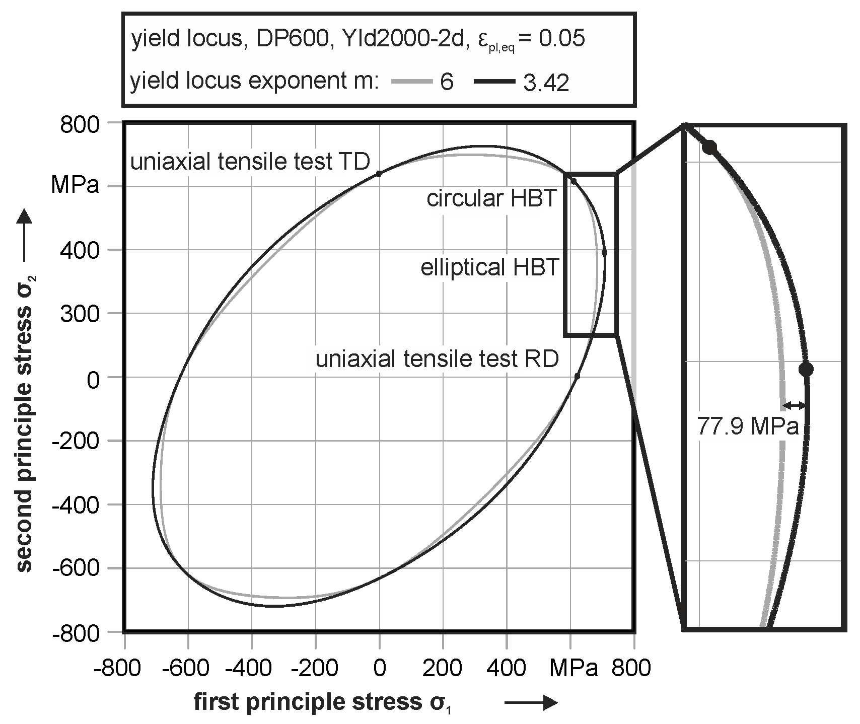
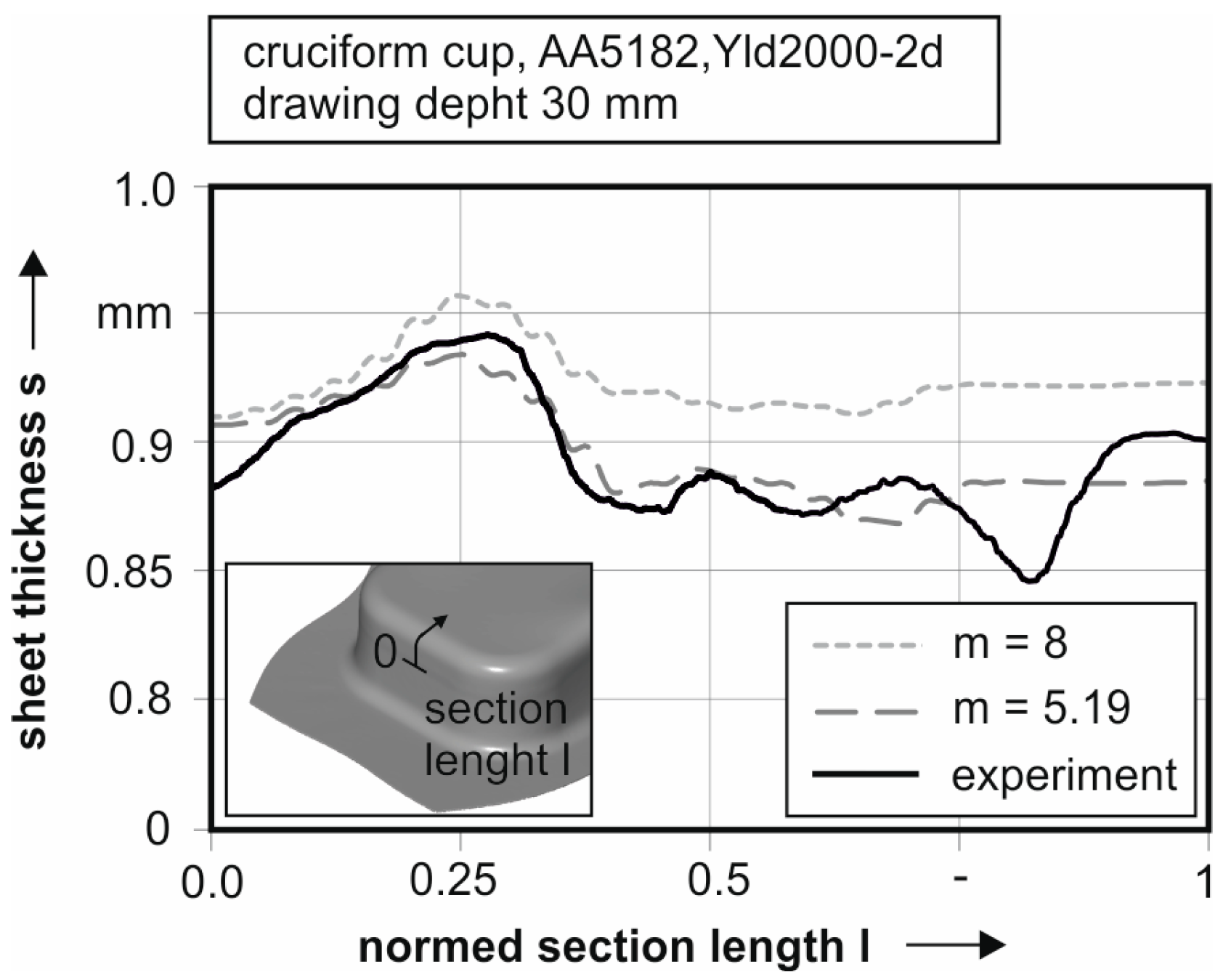
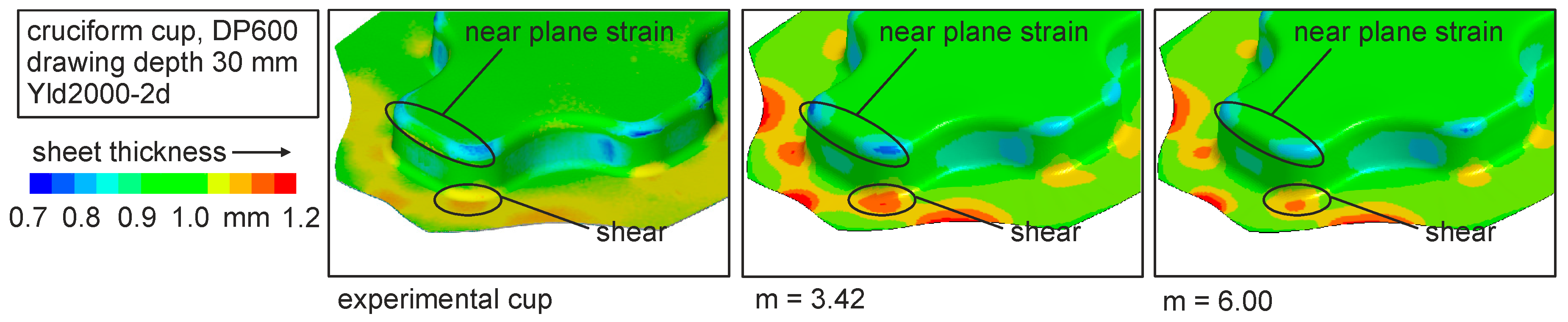
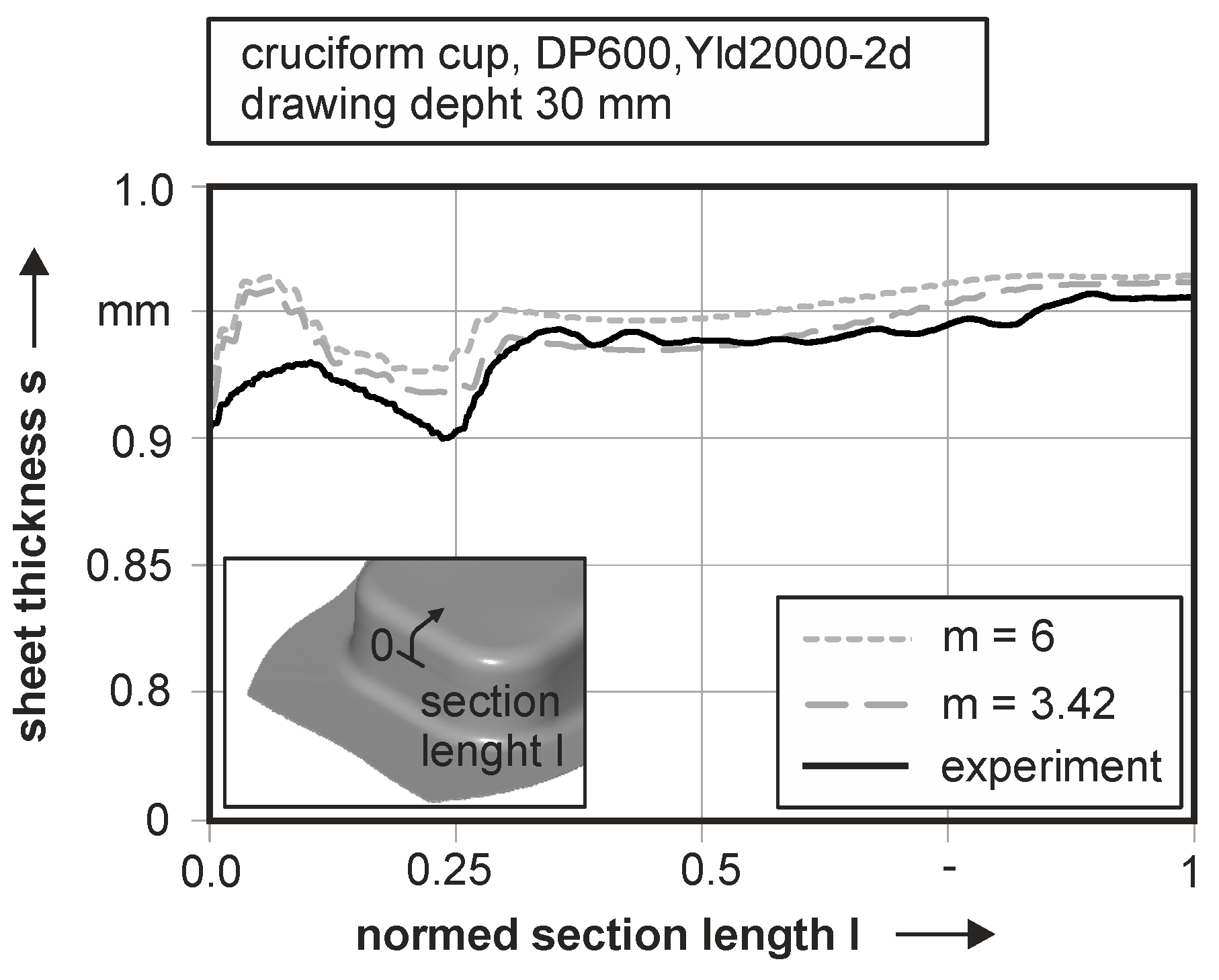
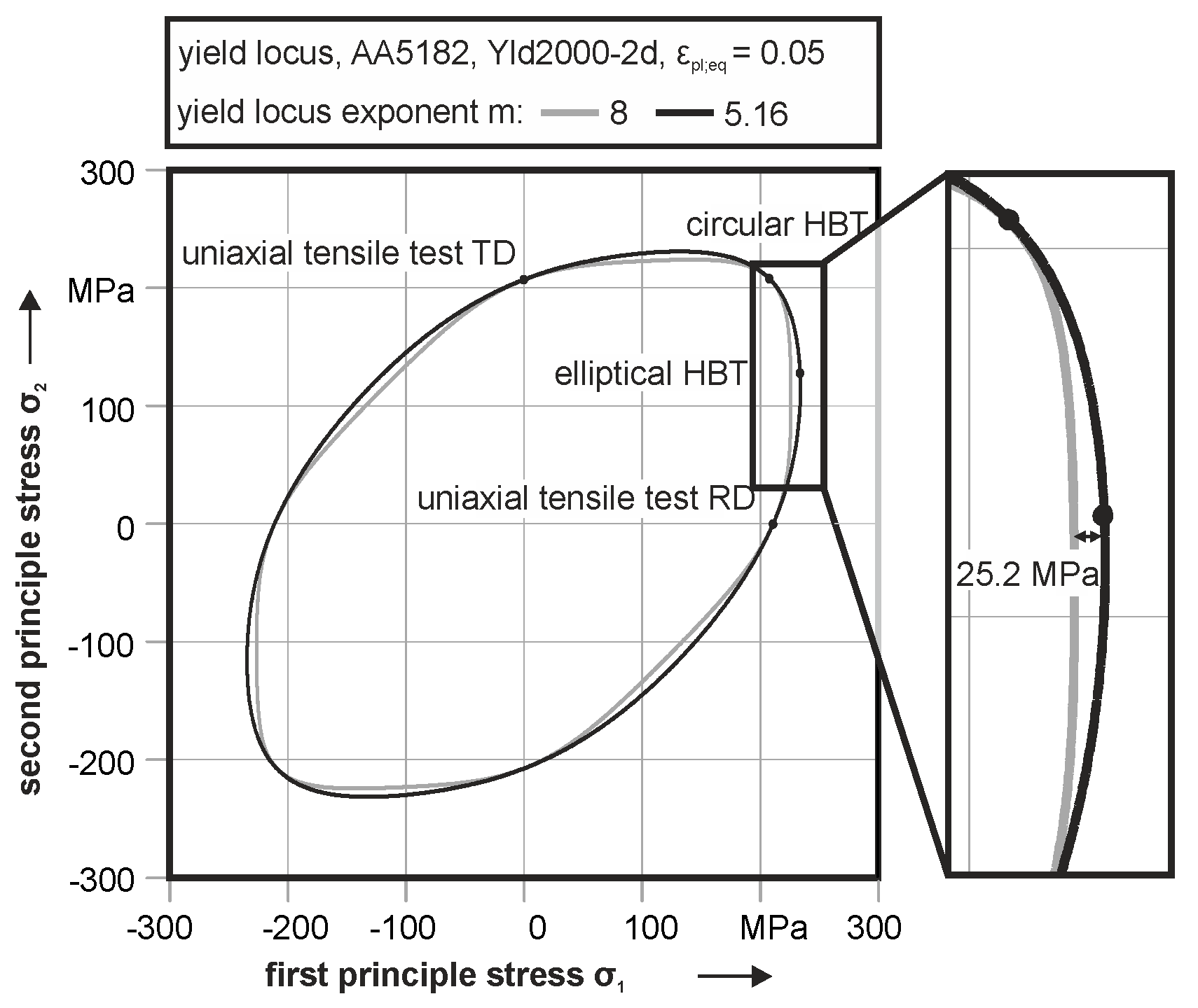
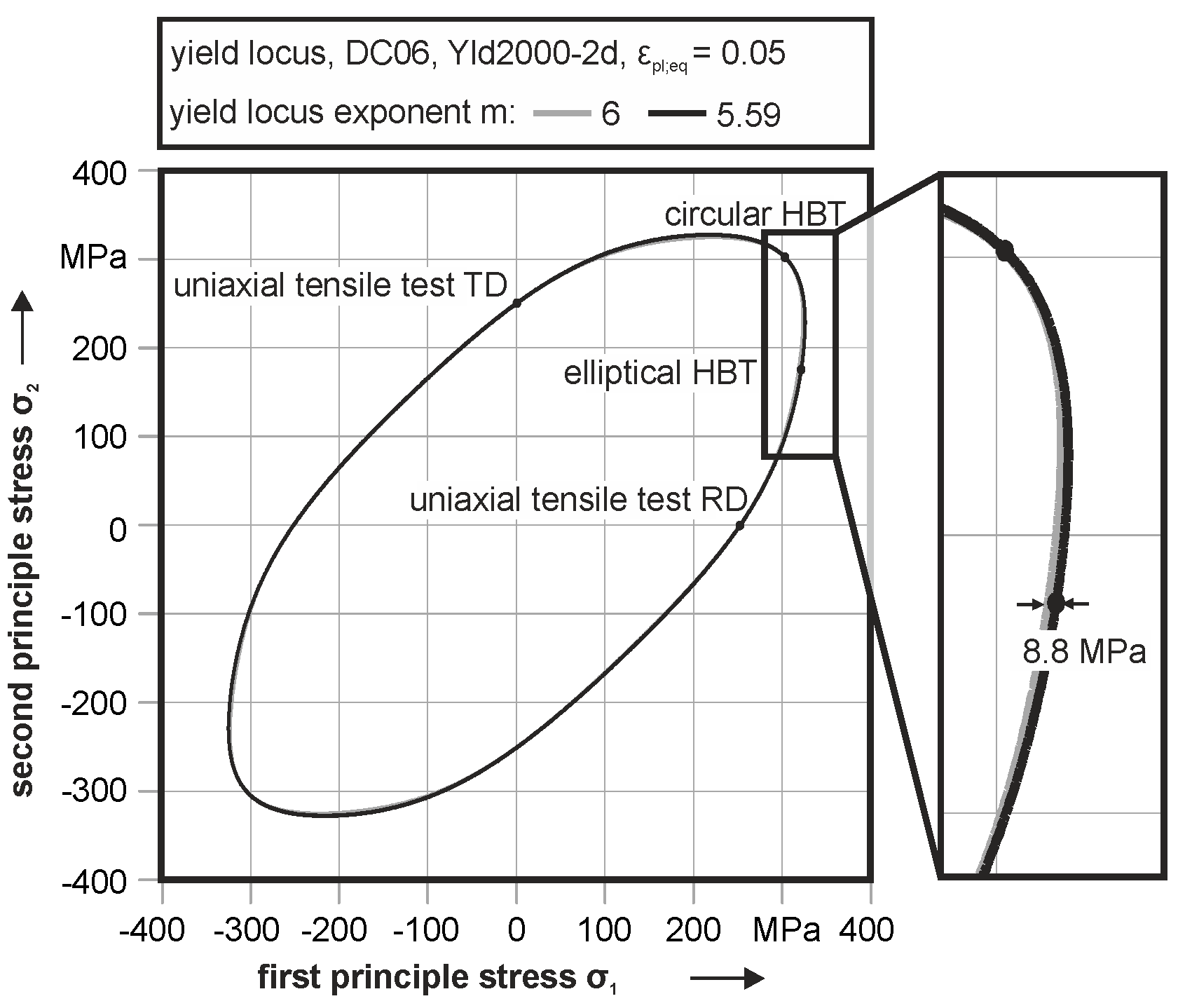
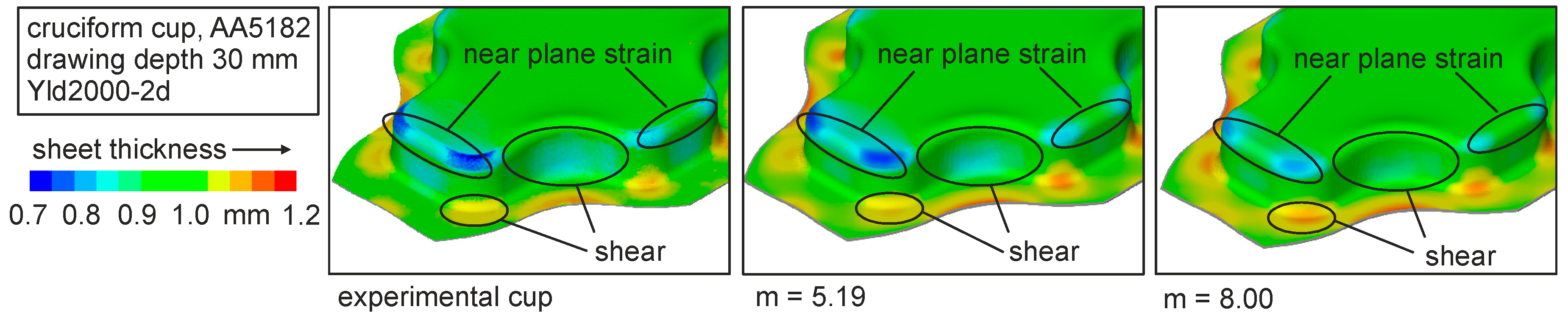
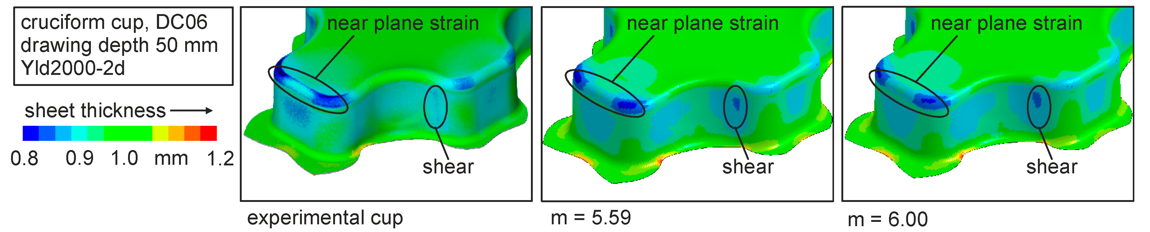
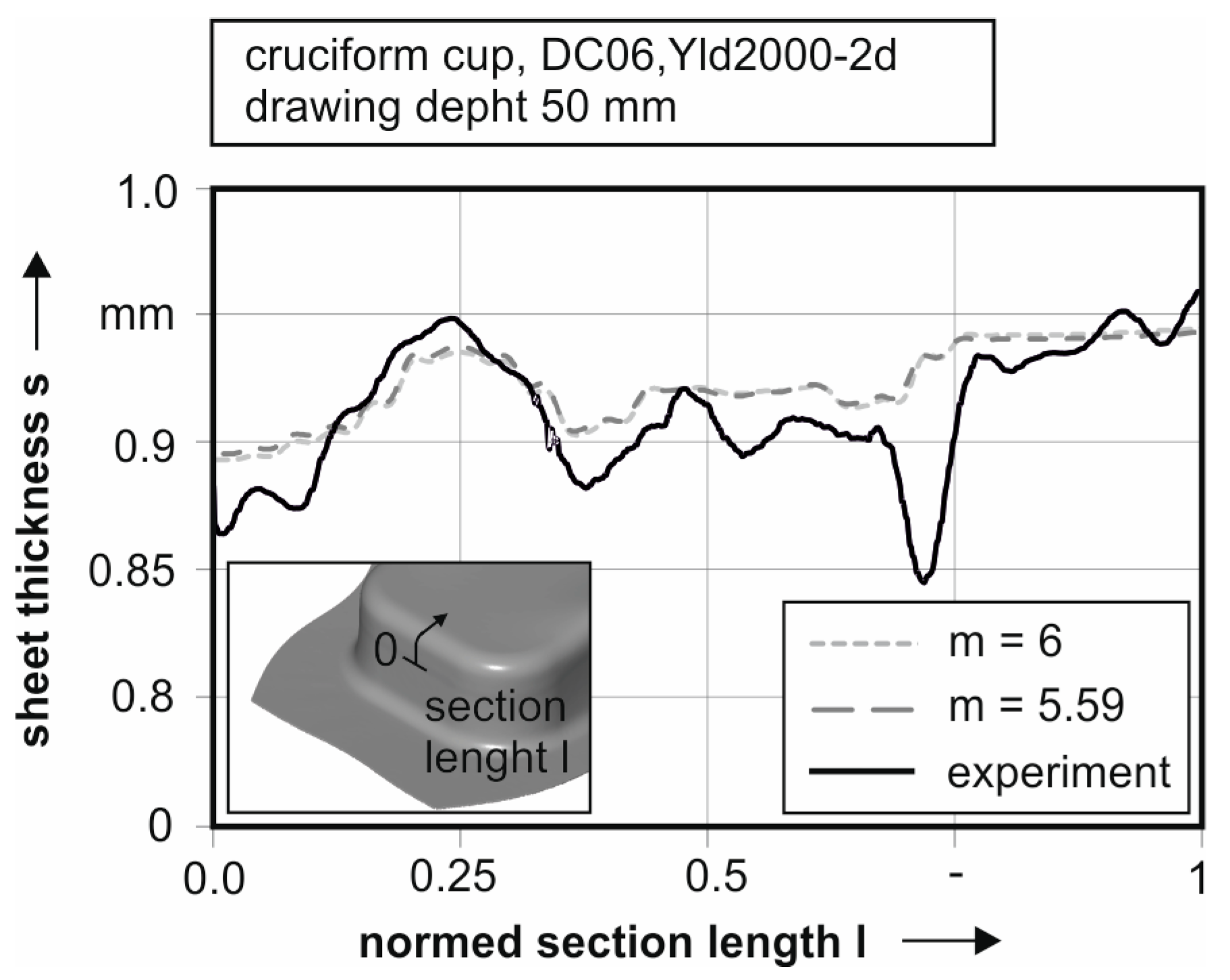
The plane strain is the most important reason for failure in a deep drawing process and therefore should be integrated in the applied material model in a process simulation. Challenge in this context is the lack of an experimental setup to characterize the plane strain material behavior. This contribution presents a testing setup to characterize the near plane strain material behavior. Therefore, a hydraulic bulge test with an elliptic die geometry is introduced. With formulations of the shell theory, the plastic material behavior can be determined in both principal directions. Results of the material characterization under plane strain for the alloys AA5182, DC06 and DP600 reveal significant differences in the hardening behavior in contrast to the conventionally used notched tensile test from a true strain of 0.05. A further advantage of the presented setup is the possibility of a characterization of both principal stress components under near plane strain conditions, whereas the notched tensile test can only determine the first principal stress. The investigation of the direction-dependent material behavior under plane strain shows no significant anisotropic plasticity. With this material information, the yield criterion Yld2000-2d is enhanced by changing the yield locus exponent to a fit of the plane strain yield locus. The results in material modelling show a significant difference for the resulting yield locus exponent m and, therefore, the yield locus geometry for AA5182 and DP600. For the DC06, a minor deviation of the yield locus exponent results when modelling the yield locus with additional material data. The realized material modelling is verified with the deep drawing process of a cruciform cup. The used geometry is suitable to induce a near plane strain state in the sheet material. Result for the AA5182 is a significant better prediction of the sheet thickness distribution in the areas of plane and shear strain. By taking into account that failure through a cup base fracture occurs at exactly this position, an improved numerical mapping is essential for this region. Due to the comparable yield locus exponents for the DC06, only a minor improvement of the mapping accuracy in numerical simulations can be observed. For the dual phase steel, again, a significant improvement of the thinning distribution is observable for the simulation with enhanced material parameters. Further thinning in the plane strain area and the shear zone are visible. Deviated from these investigations, the numerical prediction quality of a deep drawing process can be enhanced by using an experimental basis for the determination of the yield locus exponent of the yield criterion Yld2000-2d.
For a further improvement, especially for the mild steel DC06, the anisotropic hardening behavior of this material should be taken into account by using a non-associated flow rule. A possibility of using the material data for material modelling is provided by the complex anisotropic yield criterion from Vegter [25]. This flow rule is able to use the material characteristics under plane strain for material modelling. The elliptic hydraulic bulge test is able to apply this material parameter not only for the onset of yielding but also for characterizing the hardening behavior under near plane strain conditions until cracking. Using the obtained material parameter in material modelling by fitting the yield locus exponent, an improvement of the mapping accuracy can be achieved.

Author Contributions

Marion Merklein and Matthias Lenzen conceived and designed the experiments. Matthias Lenzen performed the experiments, analyzed the data and wrote the paper.

Conflicts of Interest

The authors declare no conflict of interest.

References

  1. Hariharan, K.; Prakash, R.V.; Prasad, M.S.; Reddy, G.M. Evaluation of yield criteria for forming simulations based on residual stress measurement. Int. J. Mater. Form. 2010, 3, 291–297. [Google Scholar] [CrossRef]
  2. Banabic, D. Sheet Metal Forming Processes—Constitutive Modelling and Numerical Simulation; Springer: Berlin, Germany, 2010. [Google Scholar]
  3. Xavier, M.D.; Plaut, R.L.; Schön, C.G. Uniaxial Near Plane Strain Tensile Tests Applied to the Determination of the FLC Formabillity Parameter. Mater. Res. 2014, 17, 982–986. [Google Scholar] [CrossRef]
  4. Barlat, F.; Brem, J.C.; Joon, J.W.; Chung, K.; Dick, R.E.; Lege, D.J.; Porboghrat, F.; Choi, S.-H.; Chu, E. Plane stress yield function for aluminum alloy sheets—Part 1: Theory. Int. J. Plast. 2003, 19, 1297–1319. [Google Scholar] [CrossRef]
  5. Flores, P.; Tuninetti, V.; Gilles, G.; Gonry, P.; Duchêne, L.; Habraken, A.-M. Accurate stress computation in plane strain tensile tests for sheet metal using experimental data. J. Mater. Process. Technol. 2010, 1772–1779. [Google Scholar] [CrossRef]
  6. Wagoner, R.H. Maesurement and Analysis of Plane-Strain Work Hardening. Metall. Trans. A 1980, 11, 165–175. [Google Scholar] [CrossRef]
  7. Kuwabara, T. Advances of Plasticity Experiments on Metal Sheets and Tubes and Their Applications to Constitutive Modeling. AIP Conf. Proc. 2005, 778, 20–39. [Google Scholar] [CrossRef]
  8. Hecht, J.; Pinto, S.; Geiger, M. Determination of Mechanical Properties for the Hydroforming of Magnesium Sheets at Elevated Temperature. Adv. Mater. Res. 2005, 6–8, 779–786. [Google Scholar] [CrossRef]
  9. Altan, T.; Palaniswamy, H.; Bortot, P.; Mirtsch, M.; Heidl, W.; Bechtold, A. Determination of sheet material properties using biaxial bulge tests. In Proceedings of the Second International Conference on Accuracy in Forming Technology, Chemnitz, Germany, 13–15 November 2006; pp. 79–92. [Google Scholar]
  10. Rees, D.W.A. Plastic flow in the elliptical bulge test. Int. J. Mech. Sci. 1995, 37, 373–389. [Google Scholar] [CrossRef]
  11. Lazarescu, L.; Nicodim, I.P.; Comsa, D.-S.; Banabic, D. A procedure for the evaluation of flow stress of sheet metal by hydraulic bulge test using elliptical dies. Key Eng. Mater. 2012, 504, 107–112. [Google Scholar] [CrossRef]
  12. Lazarescu, L.; Comsa, D.-S.; Nicodim, I.; Ciobanu, I.; Banabic, D. Characterization of plastic behaviour of sheet metals by hydraulic bulge test. Trans. Nonferr. Met. Soc. China 2012, 22, s275–s279. [Google Scholar] [CrossRef]
  13. Shi, B.; Peng, Y.; Yang, C.; Pan, F.; Cheng, R.; Peng, Q. Loading path dependent distortional hardening of Mg alloys: Experimental investigation and constitutive modeling. Int. J. Plast. 2017, 90, 76–95. [Google Scholar] [CrossRef]
  14. Safaei, M.; Lee, M.-G.; Zang, S.-I.; De Waele, W. An evolutionary anisotropic model for sheet metals based on non-associated flow rule approach. Comput. Mater. Sci. 2014, 81, 15–29. [Google Scholar] [CrossRef]
  15. Manopulo, N.; List, J.; Hippke, H.; Hora, P. A Non-Associated Flow Rule Based on Yld2000-2d Model. In Proceedings of the 8th Forming Technology Forum Zurich 2015, Zurich, Switzerland, 29–30 June 2016. [Google Scholar]
  16. Zang, S.-I.; Lee, M.; Kim, J.H.; Safaei, M. A new representation of linear transformation tensor for the description of plastic subsequent anisotropy. AIP Conf. Proc. 2013, 1567, 508–511. [Google Scholar] [CrossRef]
  17. Plunkett, B.; Cazacu, O.; Barlat, F. Orthotropic yield criteria for description of the anisotropy in tension and compression of sheet metals. Int. J. Plast. 2008, 24, 847–866. [Google Scholar] [CrossRef]
  18. Kuwabara, T.; Mori, T.; Asano, M.; Hakoyama, T.; Barlat, F. Material modeling of 6016-O and 6016-T4 aluminum alloy sheets and application to hole expansion forming simulation. Int. J. Plast. 2017, 93, 164–186. [Google Scholar] [CrossRef]
  19. Merklein, M.; Suttner, S.; Brosius, A. Charcaterisation of kinematic hardening and yield surface evolution from uniaxial to biaxial tension with continuous strain path change. CIRP Ann. Manuf. Technol. 2014, 14, 297–300. [Google Scholar] [CrossRef]
  20. Suttner, S.; Merklein, M. Experimental and numerical investigation of a strain rate controlled hydraulic bulge test of sheet metal. J. Mater. Process. Technol. 2016, 235, 121–133. [Google Scholar] [CrossRef]
  21. SEP 1240: 2006-07. Testing and Documentation Guideline for the Experimental Determination of Mechanical Properties of Steel Sheets for CAE-Calculations; National Standard; Beuth Verlag GmbH: Berlin, Germany, 2006. [Google Scholar]
  22. VDA 239-300: 2015-10. Experimental Determination of Mechanical Properties of Aluminium Sheets for CAE-Calculation Testing and Documentation; National Standard; Verband der Automobilindustrie e.V. (VDA): Berlin, Germany, 2015. [Google Scholar]
  23. Kollar, L.; Dulácska, E. Buckling of Shells for Engineers; John Wiley Sons: Budapest, Hungary, 1984; ISBN 978-0471903284. [Google Scholar]
  24. Jung, J.; Jun, S.; Lee, H.-S.; Kim, B.-M.; Lee, M.-G.; Kim, J.H. Anisotropic Hardening Behaviour and Springback of Advanced High-Strength Steels. Metals 2017, 7, 480. [Google Scholar] [CrossRef]
  25. Pijlman, H.H.; Huetink, H.; Meinders, V.T.; Carleer, B.D.; Vegter, H. The Implementation of the Vegter yield Criterion and a physically based hardening rule in Finite Elements. In Proceedings of the 4th International World congres on Computational Mechanics (IACM ’98), Buenos Aires, Argentine, 29 June–2 July 1998. [Google Scholar]
Figure 1. Testing setup for elliptical strain rate controlled hydraulic bulge test.
Jmmp 02 00006 g001
Figure 2. Area of evaluation for the best fit cylinders and resultant geometrical data.
Jmmp 02 00006 g002
Figure 3. Cracked specimen of DC06 for elliptic hydraulic bulge test.
Jmmp 02 00006 g003
Figure 4. Strain rate over equivalent strain (a) and resulting curvature over time (b) for elliptic hydraulic bulge test (HBT) of DC06.
Jmmp 02 00006 g004
Figure 5. True stress—true plastic strain curves with an elliptic hydraulic bulge test (HBT) according to rolling direction (RD), diagonal direction (DD) and transversal direction (TD) of AA5182.
Jmmp 02 00006 g005
Figure 6. Flow curves with an elliptic hydraulic bulge test (HBT) according to rolling direction (RD), diagonal direction (DD) and transversal direction (TD) for DC06.
Jmmp 02 00006 g006
Figure 7. True principle stress—true plastic strain curves with an elliptic hydraulic bulge test (HBT) according to rolling direction (RD) and transversal direction (TD) of DP600.
Jmmp 02 00006 g007
Figure 8. Von Mises equivalent stress-strain curves for DC06, DP600 and AA6016.
Jmmp 02 00006 g008
Figure 9. Evaluation area in elliptic hydraulic bulge test for determination of the curvature via best fit cylinders.
Jmmp 02 00006 g009
Figure 10. Resulting strain path in the pole of the elliptic specimen in contrast to the resulting forming limit curve (FLC) according to DIN EN ISO 12004-2 for DC06.
Jmmp 02 00006 g010
Figure 11. Equivalent stress-strain curve for circular and elliptical HBT for AA5182, DC06 and DP600.
Jmmp 02 00006 g011
Figure 12. Flow curves of notched tensile tests in rolling direction (RD) and elliptic hydraulic bulge tests HBT in transversal direction (TD) for AA5182, DC06 and DP600.
Jmmp 02 00006 g012
Figure 13. Methodology for the mapping of the yield locus under plane strain conditions through variation of the yield locus exponent m.
Jmmp 02 00006 g013
Figure 14. Yield loci of AA5152 with conventional and optimized yield locus exponent m.
Jmmp 02 00006 g014
Figure 15. Yield loci of DC06 with conventional and optimized yield locus exponent m.
Jmmp 02 00006 g015
Figure 16. Yield loci of DP600 with conventional and optimized yield locus exponent m.
Jmmp 02 00006 g016
Figure 17. Sheet thickness of cruciform cups of A5182 for different yield locus exponents in simulations and experimental result.
Jmmp 02 00006 g017
Figure 18. Sheet thickness progression in the plane strain area of the punch radius for simulations with different yield locus exponent and experimental measurement for AA5182.
Jmmp 02 00006 g018
Figure 19. Sheet thickness of cruciform cups of DC06 for different yield locus exponents in simulations and experimental result.
Jmmp 02 00006 g019
Figure 20. Sheet thickness progression in the plane strain area of the punch radius for simulations with different yield locus exponent and experimental measurement for DC06.
Jmmp 02 00006 g020
Figure 21. Sheet thickness of cruciform cups of DP600 for different yield locus exponents in simulations and experimental result.
Jmmp 02 00006 g021
Figure 22. Sheet thickness progression in the plane strain area of the punch radius for simulations with different yield locus exponent and experimental measurement for DP600.
Jmmp 02 00006 g022
Table 1. Mechanical properties of the materials AA5182-O, DC06 and DP600 derived from material characterization.
MaterialSheet Thickness t0 (mm)Yield Stress Y0.2 (MPa)Tensile Strength TS (MPa)
AA5182-O1.0120–125260–270
DC061.0165–180285–300
DP6001.0400–405645–650
Table 2. Process parameters used for deep drawing process and simulation of a cruciform cup.
MaterialBlank Holder Force (kn)Drawing Depth (mm)
AA5182-O10030
DC0640050
DP60030030
Table 3. Conventional identified parameters for the yield criterion Yld2000-2d for AA5182, DC06 and DP600.
MaterialAlpha 1Alpha 2Alpha 3Alpha 4Alpha 5Alpha 6Alpha 7Alpha 8Yield Locus Exponent
AA51820.99370.96800.96501.02981.01691.02720.97321.05648
DC060.99461.11060.78040.87440.89110.68420.99601.04786
DP6000.95700.99981.08791.00241.01460.98300.96610.98666
Table 4. Identified parameters for the yield criterion Yld2000-2d with experimental determined yield locus exponent under plane strain for AA5182, DC06 and DP600.
MaterialAlpha 1Alpha 2Alpha 3Alpha 4Alpha 5Alpha 6Alpha 7Alpha 8Yield Locus Exponent
AA51821.07080.84660.88891.03831.02081.07170.92771.09545.16
DC060.98731.12610.80220.86960.88890.67471.00041.04425.59
DP6001.19060.74090.84301.00011.01611.20060.94971.02933.42

