Article

A Two-Layer Framework for Cooperative Standoff Tracking of a Ground Moving Target Using Dual UAVs

by
Jing Chen
1,
Dong Yin
1,2,*,
Jing Fu
1,
Yirui Cong
1,2,
Hao Chen
1,2,
Xuan Yang
3,
Haojun Zhao
1 and
Lihuan Liu
1
1
College of Intelligence Science and Technology, National University of Defense Technology, Changsha 410073, China
2
National Key Laboratory of Equipment State Sensing and Smart Support, National University of Defense Technology, Changsha 410073, China
3
Northwest Institute of Mechanical and Electrical Engineering, Xianyang 712099, China
*
Author to whom correspondence should be addressed.
Drones 2025, 9(8), 560; https://doi.org/10.3390/drones9080560
Submission received: 16 June 2025 / Revised: 3 August 2025 / Accepted: 6 August 2025 / Published: 9 August 2025

Abstract

Standoff tracking of a ground-moving target with a single fixed-wing unmanned aerial vehicle (UAV) is vulnerable to occlusions around the target, such as buildings and terrain, which can obstruct the line of sight (LOS) between the UAV and the target, resulting in tracking failures. To address these challenges, multi-UAV cooperative tracking is often employed, offering multi-angle coverage and mitigating the limitations of a single UAV by maintaining continuous target visibility, even when one UAV’s LOS is obstructed. Building on this idea, we propose a specialized two-layer framework for dual-UAV cooperative target tracking. This framework comprises a decision-making layer and a guidance layer. The decision-making layer employs a state-transition-based distributed role transition algorithm for dual UAVs. Here, the UAVs periodically share state variables based on their target observability. In the guidance layer, we devise a velocity-vector-field-based controller to simplify the complexity of controller design for cooperative tracking. To validate the proposed framework, three numerical simulations and one hardware-in-the-loop (HIL) simulation were conducted. These simulations confirmed that the role transition algorithm functions properly even under occlusion conditions. Additionally, the standoff tracking guidance controller demonstrated superior performance compared to baseline methods in terms of tracking accuracy and stability.

1. Introduction

Fixed-wing unmanned aerial vehicles (UAVs) are extensively used in various military and civilian applications, such as military reconnaissance [1], target tracking [2], emergency communication [3], and disaster monitoring [4], due to their long endurance, high flight speed, and capability to cover large areas. In the context of tracking ground-moving targets, fixed-wing UAVs are particularly effective for wide-area, persistent surveillance because of their speed, extended operational duration, maneuvering capabilities, and payload capacity [5]. Standoff tracking [6] is a typical method for target tracking, where UAVs maintain a fixed distance from the target to ensure continuous observation [7,8]. However, single-UAV tracking is inherently limited by its fixed observation angle, resulting in constrained coverage and increased vulnerability to occlusions caused by objects surrounding the target, thereby significantly reducing the UAV’s ability to observe the target effectively [9].
Consensus-based formation control principles provide the foundational coordination mechanisms for aerial multi-agent systems, which have been leveraged to advance cooperative standoff tracking technologies using multiple UAVs. This approach addresses the limitations of single-UAV tracking, such as fixed observation angles and vulnerability to environmental occlusions, by employing UAVs that follow circular trajectories with fixed relative phase offsets. This strategy enables complementary coverage and prevents collisions [10]. For instance, dual-UAV tracking establishes an optimal observation region with a symmetrical 180° distribution around the target [11]. Additionally, multi-UAV tracking improves target localization accuracy by integrating observations [12,13] and employing field-of-view sharing mechanisms to ensure stable tracking in suboptimal observation conditions [14].
In UAV target tracking, existing methods include Lyapunov-vector-field-based approaches (LVF), model predictive control (MPC), τ -guidance vector fields, and reference point guidance (RPG). Among these, Lawrence D. [15] pioneered the application of Lyapunov-guided vector fields for single-UAV standoff tracking. Subsequently, Frew E. W. [6] expanded this technique to facilitate multi-UAV coordination through velocity control. To expedite trajectory convergence, Chen H. [16] introduced tangential vector fields. Oh H. et al. [17] integrated sliding mode control to enhance dynamic adaptability. Regarding parameter optimization, Lim S. [18] introduced a guidance parameter c to synchronize convergence position and time. Pothen A. [19] and Sun S. et al. [20] utilized linear and exponential functions to constrain c and ensure steering angle limits, with the latter compromising real-time performance due to offline optimization. Chao [21] developed a decentralized coordination strategy within the framework of model predictive control (MPC) for multiple UAVs to track unknown ground targets. Shun [22] introduced an MPC-based observation-driven approach to enhance the tracking precision of maneuvering targets by optimizing the observation angles of UAVs. Zhu et al. [23] addressed cooperative hovering and tracking of randomly moving targets using only angle measurements in a dual-UAV scenario, employing nonlinear model predictive control (NMPC) for distributed online optimization. However, the practical implementation complexity of MPC methods is heightened by the necessity for an accurate model of the controlled system, which increases their complexity in practical implementation. Furthermore, Yang et al. [24] proposed a time-constrained cooperative standoff tracking method by establishing τ -guidance vector fields to achieve fixed-distance circling control of UAVs around moving targets. Park et al. [25,26] proposed an RPG method for UAV path-following. This method determines lateral acceleration directives by considering the UAV’s velocity and the trajectory of a reference point along the flight path. Huang [27] proposed a composite method that combines reference point guidance with adaptive proportional-derivative (PD) control. This method incorporates segmented switching and dynamic compensation to enhance Lyapunov vector field guidance (LVFG) convergence and improves the accuracy of RPG tracking for moving targets. The proposed approach ensures stable tracking performance and enhances anti-interference capabilities in UAV surveillance operations.
Despite significant progress in UAV tracking research, critical gaps remain in addressing challenges caused by occlusions. Single-UAV tracking is limited by fixed observation angles, restricting the system’s ability to overcome environmental occlusions such as buildings and terrain, which results in tracking interruptions or failures. Although multi-UAV cooperative approaches strategies enhance robustness by providing multiple observational perspectives, current methods lack specialized mechanisms for sharing data sharing in occluded scenarios. This deficiency results in insufficient system redundancy and adaptability in real-world applications due to inadequate integration of dynamic role division and target data sharing strategies. Additionally, existing control methods still have shortcomings in tracking accuracy and convergence speed.
To address these challenges, we propose a dual-layer tracking framework consisting of a decision-making layer and a guidance layer. The decision-making layer manages roles during occlusion events using a dynamic role transition mechanism based on real-time target observability. The UAV with unobstructed observability is designated as the Master node, while the others operate as Slave nodes relying on target data provided by the Master. If both UAVs achieve equal unobstructed observability, the system enters standby mode, allowing the simultaneous use of self-acquired target states. This multi-source data sharing improves tracking stability. In the guidance layer, a velocity-vector-field-based controller law is implemented to enhance tracking performance. The two-dimensional operational space is treated as a field domain with field sources comprising the target position, cooperative UAV states, and desired trajectory. The UAVs generate a synthesized velocity vector influenced by this field, with its magnitude and direction determining real-time control commands.
This work presents three main contributions: First, we introduce a two-layer framework that enhances target tracking stability and continuity via real-time Master–Slave role transition, guided by observability metrics and supported by distributed information sharing. Second, we develop a velocity-vector-field-based controller that ensures asymptotic convergence to a desired standoff radius R, maintaining an optimal 180° phase separation between the dual UAVs, with stability validated through Lyapunov analysis. Third, we propose a distributed state-transition-based role transition algorithm that enables real-time Master–Slave arbitration through the observability of the target, ensuring effective role division.
The paper is structured as follows: Section 2 formulates the role transition and the kinematic model of UAVs, establishing the theoretical foundation for cooperative tracking. Section 3 details the proposed two-layer framework: (i) the decision-making layer utilizing state-transition-based role transition and (ii) the guidance layer employing velocity vector field synthesis. Section 4 offers Lyapunov stability proofs for radial convergence and phase synchronization. Section 5 validates the method with numerical and hardware-in-the-loop (HIL) simulations. Section 6 summarizes our study and discusses future work.

2. Problem Formulation

2.1. Role Transition Model

The observability of a target from UAVs is significantly affected by environmental factors, particularly visual occlusions caused by buildings, terrain, and other objects that obstruct the line of sight (LOS), as depicted in Figure 1. This study addresses these challenges by implementing a cooperative role transition mechanism between dual UAVs to ensure continuous tracking.
Figure 2 depicts the collaborative mechanism between dual UAVs, where the Master and Slave roles dynamically transition according to the division of labor. This role transition dictates the status of target states sharing as follows:
  • Single-Observer Mode: When a UAV ensures continuous and stable observation of the target, it assumes the role of Master, providing the target states to the Slave, which is unable to ensure stable observation caused by occlusion.
  • Dual-Observer Mode: When the Slave UAV’s visual occlusion is cleared, the system activates Dual-Observer Mode, retaining the Master–Slave roles established in Single-Observer Mode. Both UAVs share the target states they acquire, allowing for an exchange of acquired target states.
  • If either the Master or Slave UAV is unable to maintain target observation during Dual-Observer Mode, resulting in a loss of target sight, the system automatically reverts to Single-Observer Mode.

2.2. UAV Kinematic Model

For the analysis and control design, we assume the UAVs maintain a constant altitude, with all maneuvers confined to the horizontal plane. In the plane’s coordinate system, the x axis points east, the y axis north, and the angle ψ within ( π , π ] is measured counterclockwise from the x axis. The motion of the i-th UAV is described by the unicycle model [28], where ( x i , y i ) represents the UAV’s position, v i is its linear speed, ψ i is its heading angle, and ω i is its angular rate. The model is expressed as follows:
x ˙ i = v i cos ψ i y ˙ i = v i sin ψ i ψ ˙ i = ω i
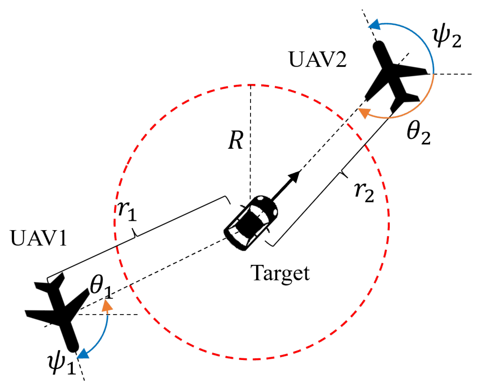
As shown in Figure 3, two UAVs perform cooperative standoff tracking of a single ground-moving target, with R denoting the desired standoff distance. Given the target’s position ( x t , y t ) , the relationship between UAV i and the target is expressed as follows:
r i = ( x i x t ) 2 + ( y i y t ) 2 θ i = arctan y t y i x t x i
In Equation (2), r i denotes the distance from the i-th UAV to the target, and θ i represents the LOS angle measured from the UAV i to the target relative to the x axis. Next, we will design the control law to ensure the UAVs maintain a distance of radius R from the target and achieve a 180° phase difference in θ between them.

3. Two-Layer Tracking Framework Design

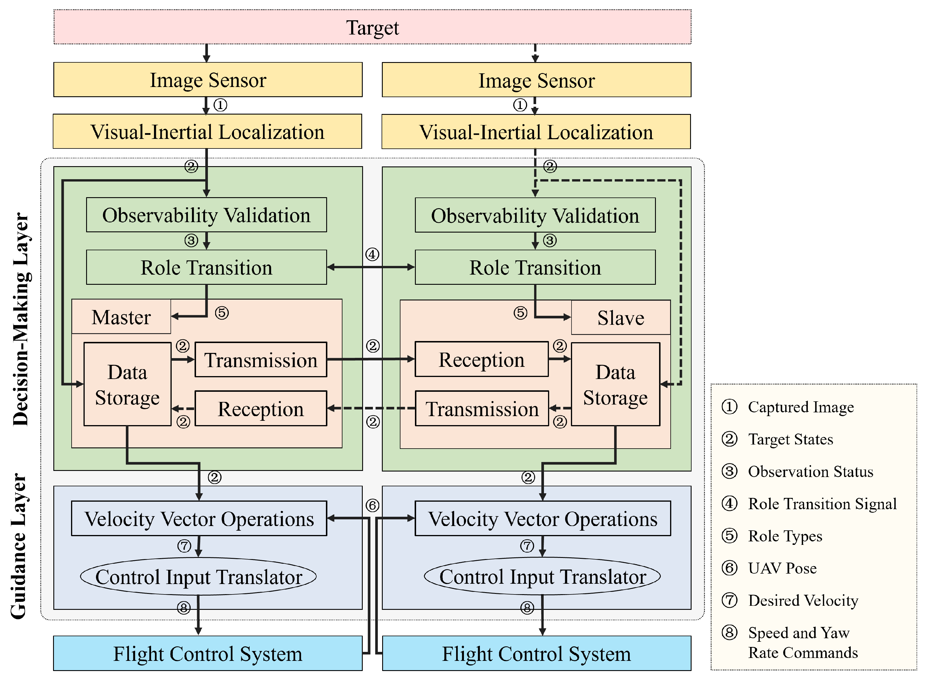
To elucidate the relationship between the proposed framework and the UAV platform architecture, we present the system configuration in Figure 4. The following assumptions underpin the hierarchical architecture design and facilitate experimental validation.
Assumption 1.
Each UAV is equipped with an imaging and visual-inertial localization module, enabling real-time estimation of the target pose ( x t , y t ) and derivation of the target velocity ( v t ) and heading ( ψ t ) through visual–inertial fusion algorithms.
Assumption 2.
The flight control systems enable constant-altitude operation, trajectory tracking via ω i - v i control inputs, and compliance with the unicycle kinematic model, ensuring seamless integration of hardware capabilities with algorithmic design.
Based on the stated assumptions, we propose a two-layer framework depicted in Figure 4. In this dual-UAV cooperative tracking architecture, each UAV integrates five elements: a decision-making layer, a guidance layer, an image sensor, a visual–inertial localization system, and a flight control system. The design ensures robustness in complex occlusion environments via a distributed information interaction mechanism. Importantly, the image sensor, visual–inertial localization system, and flight control system utilize existing modules, while the decision-making and guidance layers embody the algorithmic advancements of this study. Dotted lines indicate that in Single-Observer Mode, the Slave UAV cannot capture target images using its own image sensor, resulting in invalid data along the corresponding paths.
The decision-making layer inputs and outputs the target poses to continuously supply the guidance layer, facilitated by the Master–Slave role division. It comprises five modules: observability validation, role transition, storage, transmission, and reception. The guidance layer receives the UAVs’ and the target’s poses, outputting yaw rate and speed commands to execute the tracking guidance law via the velocity vector field. It includes two modules: velocity vector operations and a control input translator. The functions of these modules and the transmitted signals are detailed in Figure 4 and Table 1.

3.1. Decision-Making Layer

This section proposes a state-transition-based distributed algorithm for role transitions in dual-UAV systems. The algorithm achieves Master–Slave role transition through a state-driven decision-making mechanism. The process is detailed as follows.
Each UAV, denoted as UAV i, generates a binary state variable s ( i , t ) based on the target observability at time t, which is defined as
s ( i , t ) = 1 , if UAV i can observe the target , 0 , if UAV i cannot observe the target .
Additionally, s ( i , t 1 ) records the historical state at time t 1 .
The i-th UAV transmits a state tuple ( s ( i , t ) , s ( i , t 1 ) ) to other UAVs periodically with a period T p u b . The receiver performs time synchronization verification as follows:
max i j , i , j { 1 , 2 } | t i t j | < Δ t sync
where Δ t s y n c is the synchronization threshold. Data exceeding the timeout will be discarded.
Upon exchanging state tuples, each UAV acquires the other’s state information, thus forming the following joint state space:
Φ = ( s ( 1 , t ) , s ( 1 , t 1 ) , s ( 2 , t ) , s ( 2 , t 1 ) )
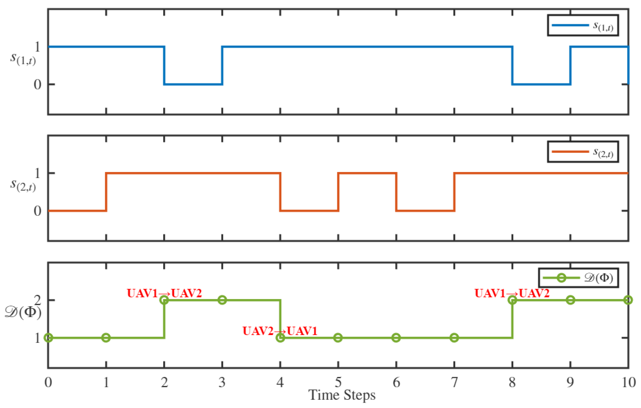
Using the state transition function D ( Φ ) , the decision is made according to reference Table 2.
D ( Φ ) = 1 , UAV 1 is transitions the Master role , 2 , UAV 2 is transitions the Master role , 0 , the last valid decision is retained , 1 , the state is invalid or undecidable .
The relationship between the state transition function D ( Φ ) and the state variables of the UAVs is also intuitively illustrated in Figure 5.
The proposed role transition mechanism exhibits the following characteristics:
  • Identity Independence: Both nodes execute identical code, and UAV roles dynamically transition in real-time based on target observability.
  • Bounded Delay: The decision synchronization delay is bounded by τ d e c i s i o n < 2 T p u b + Δ t s y n c .

3.2. Guidance Layer

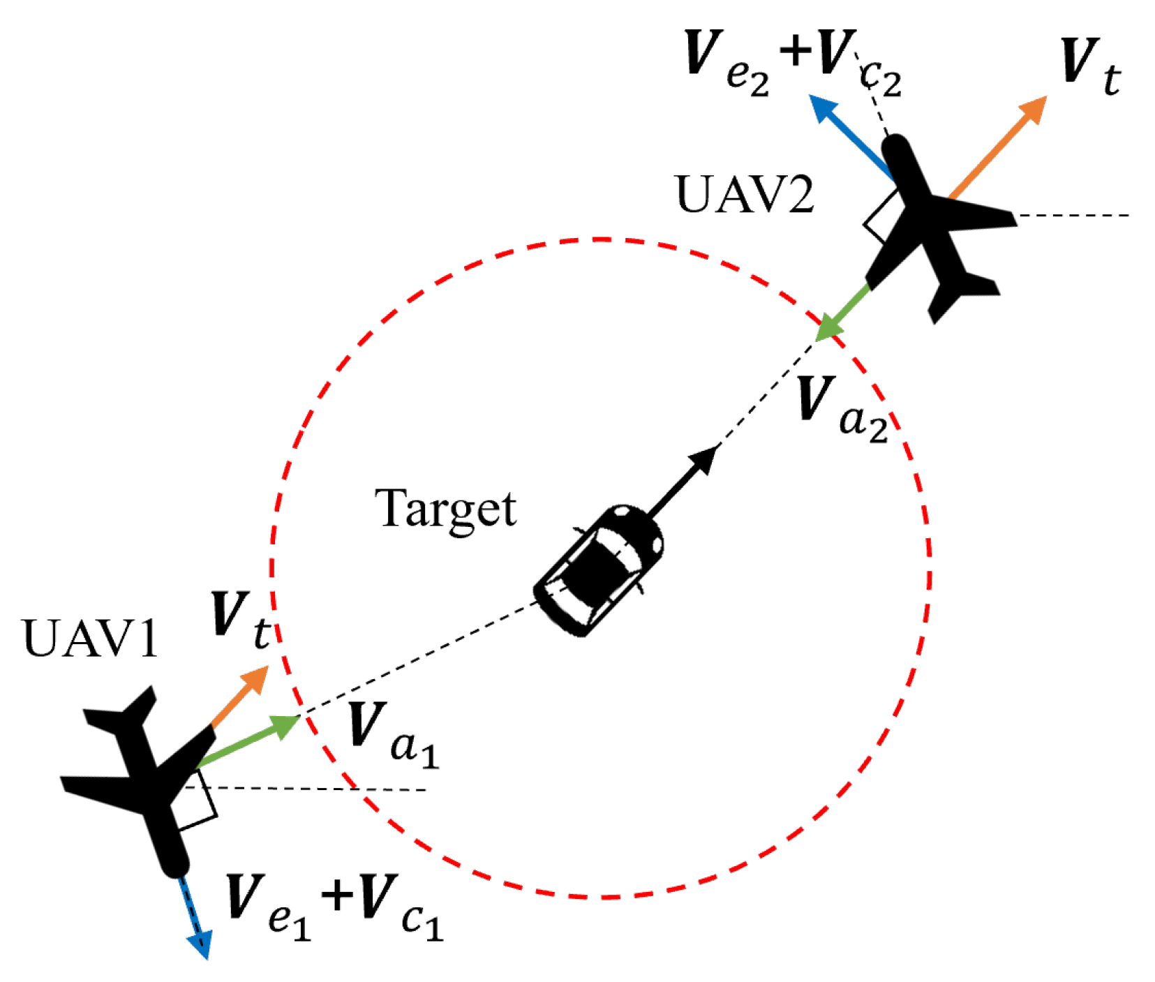
As illustrated in Figure 6, the motion of the UAVs can be considered the superposition of velocities in four distinct directions: tracking velocity, approach velocity, circling velocity, and coordination velocity.
Specifically, these velocities are defined as follows: The tracking velocity V t matches the target’s velocity in both magnitude and direction; the approach velocity V a aligns with the line connecting the UAV and the target, proportional to the difference r R ; and the circling velocity V e , whose magnitude is related to r R , is perpendicular to V a . When n UAVs cooperate to track a single target, maintaining a consistent LOS angle with a phase difference of 2 π / n , a coordination velocity V c is introduced. This velocity is parallel to V e , and its magnitude is proportional to the phase difference among the UAVs, adjusting their circling speed.
Based on the above analysis, the resultant velocity V i applied to the i-th UAV can be expressed as
V i = V t + V a i + V e i + V c i
Expanding the above equation yields
x ˙ i y ˙ i = v t cos ψ t sin ψ t V t + v a i cos θ i sin θ i V a i + [ v e i + v c i ] ± sin θ i cos θ i V e i + V c i
By configuring the equation to sin θ i and cos θ i , the i-th UAV’s circling and coordination velocities are oriented counterclockwise; otherwise, they are oriented clockwise. In the subsequent analysis and experiments, we will use the counterclockwise direction as an example.
The approach velocity v a i for the i-th UAV is determined by the control law:
v a i = K p · e i ( t ) + K i · t 0 t e i ( t ) d t
where e i ( t ) = r i R defines the distance error between the UAV and the target, with K p and K i ( K p > 0 and K i > 0) as the proportional and integral gains, respectively.
The nominal circling velocity v e i , is given by
v e i = λ · v cruise
where v cruise is the UAV’s standard cruise speed at the current altitude, and the smoothing coefficient λ is defined as
λ = 1 e 1 / | e i ( t ) / μ | + 1
where μ > 0 is a smoothness that controls the transition rate. When the UAV’s distance to the target far exceeds R, v e i approaches 0. As the distance nears the standoff radius, v e i approaches v cruise .
The coordination velocity v c i for the UAV is calculated by
v c i = λ · ω c i · r i
where λ is defined as in Equation (11). The term ω c i is determined using a phase consensus algorithm, as described below:
ω c i = j = 1 n a i , j · sin ( θ i θ j Δ i , j )
where a i , j is the ( i , j ) -th element of the adjacency matrix A, characterizing the communication link status between UAV i and j . The variables θ i and θ j denote their respective LOS angles to the target, and Δ i , j = ( i j ) 2 π / n denotes the desired phase offset.
The resultant vector V i derived from Equation (7) is decomposed into the speed v i and yaw rate ω i through the following kinematic transformations:
v i = V i ω i = ( v i v last ) / Δ t
where · denotes the Euclidean norm; v last represents the speed at the previous timestep t 1 ; and Δ t is the time interval.
The computed values ( v i , ω i ) from Equation (14) are input to the flight controller of the i -th UAV. This closed-loop control formulation enables cooperative standoff tracking.

4. Stability Analysis

To establish stability, we assume the following: (i) System dynamics are locally Lipschitz continuous, guaranteeing solution existence and uniqueness. (ii) The communication topology G of the UAVs is strongly connected and balanced, promoting phase synchronization.

4.1. Radial Distance Stability

Theorem 1
(Radial Convergence). Under the proposed control law (14), the relative distance r ( t ) asymptotically converges to the standoff radius R , satisfying
lim t r ( t ) = R
Proof of Theorem 1.
Taking the time derivative of the squared relative distance r 2 = ( x x t ) 2 + ( y y t ) 2 yields
r ˙ r = ( x x t ) ( x ˙ x ˙ t ) + ( y y t ) ( y ˙ y ˙ t )
Thus,
r ˙ = x x t r ( x ˙ x ˙ t ) + y y t r ( y ˙ y ˙ t )
Using the geometric relationships cos θ = ( x t x ) / r and sin θ = ( y t y ) / r , and expanding the velocity terms from (8), we obtain
r ˙ = cos θ v a cos θ + ( v e + v m ) sin θ sin θ v a sin θ ( v e + v m ) cos θ = v a
Let the tracking error be defined as e ( t ) = r ( t ) R . Substituting the PI control law v a = K p e ( t ) + K i t 0 t e ( τ ) d τ results in the following error dynamic:
e ˙ ( t ) = K p e ( t ) K i t 0 t e ( τ ) d τ
Consider a Lyapunov function candidate:
V r ( e ) = 1 2 e 2 + K i 2 t 0 t e ( τ ) d τ 2 0
Its time derivative along system trajectories is
V r ˙ = e e ˙ + K i t 0 t e ( τ ) d τ e = K p e 2 0
Given the locally Lipschitz continuous system dynamics, a unique solution exists. According to LaSalle’s invariance principle, all trajectories converge to the largest invariant set M = { e = 0 } . Here, V r ˙ = 0 ensures e ( t ) 0 asymptotically as t . □
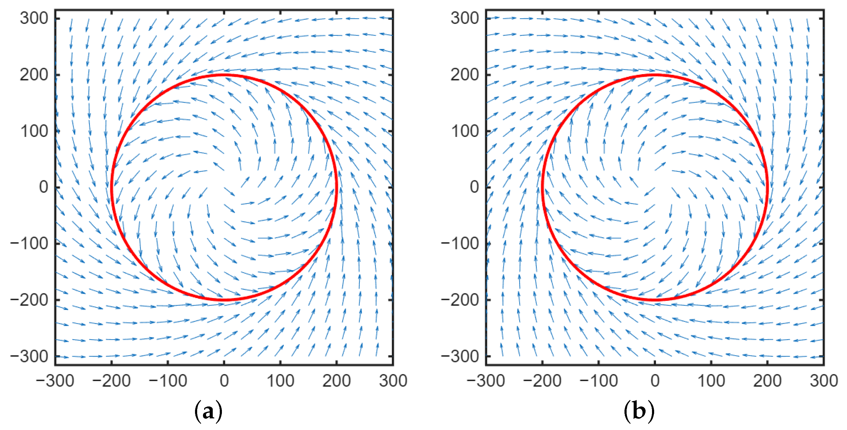
As shown in Figure 7, the velocity vector field has the following characteristics:
  • When r < R , the vector field diverges outward toward the circle of radius R ;
  • When r > R , the vector field converges inward toward the circle of radius R .
Theoretical analysis shows that the designed control law ensures the UAV trajectory asymptotically converges to a circular orbit of radius R .

4.2. Phase Synchronization Stability

Theorem 2
(Phase Convergence). Let G be a strongly connected and balanced digraph topology for n UAVs. Under the proposed control law (13), the UAVs can achieve
lim t ( θ i θ j Δ i , j ) = 0 .
Proof of Theorem 2.
We begin by defining the phase error variable η i = θ i 2 π i n , which transforms the phase difference error into
θ i θ j Δ i , j = η i η j
Substituting this transformation into the dynamics of the system, we obtain
η ˙ i = j = 1 n a ij sin ( η i η j )
To analyze the stability of the system, we define a Lyapunov function as follows:
V θ ( η ) = 1 2 i = 1 n j = 1 n a ij 1 cos ( η i η j ) 0 ,
whose time derivative is given by
V θ ˙ = i = 1 n j = 1 n a ij sin ( η i η j ) 2 0
Since V θ ( η ) 0 and V θ ˙ 0 for all η , the system is stable in the sense of Lyapunov.
By LaSalle’s invariance principle, the trajectories converge to the largest invariant set S, where
S = η j = 1 n a ij sin ( η i η j ) = 0 , i
In strongly connected and balanced digraphs G solutions in S satisfy η i     η j   =   0 . Therefore, the only asymptotically stable equilibrium is η i   =   η j , satisfying
lim t η i η j = 0
which implies
lim t ( θ i θ j Δ i , j ) = 0
Thus, we have shown that the phase convergence condition in Equation (22) holds. □

4.3. Comprehensive Analysis

According to Equations (11)–(13), the coordination velocity is defined as
v c i = r i e 1 / | e i ( t ) / μ | + 1 j = 1 n a i , j · sin ( θ i θ j Δ i , j )
While radial convergence and phase convergence are analyzed independently, the coordination velocity creates a coupling between these two processes.
As radial convergence occurs ( t , r R ), we have
r i e 1 / | e i ( t ) / μ | + 1 R / 2
This convergence is determined by the distance error between the UAV and the target. Consequently, the coordination velocity, which involves both the radial distance and phase difference terms, will also converge over time. Therefore, as t , we expect that r i R and the phase difference θ i θ j Δ i , j 0 simultaneously.

5. Simulation and Analysis

5.1. Numerical Simulation Setup

To validate the proposed two-layer framework within the GNU Octave 9.3.0 simulation environment, we designed a simulation setup consisting of three scenarios: performance validation of stationary target tracking, phase-synchronized cooperative tracking of a maneuvering target, and occlusion-robust tracking with dynamic role transition.
The first scenario evaluates the radius convergence performance of the proposed algorithm in tracking a stationary target, comparing it with the algorithms from [6,29]. The second scenario examines the cooperative tracking capability of the algorithm in a dual-UAV setup for tracking a maneuvering target, with [6] serving as a baseline. The third scenario tests the robustness and effectiveness of the proposed method under temporary occlusion, focusing on dynamic role transition between the UAVs to ensure continuous tracking.
Figure 8 depicts the target’s movement in the moving target scenario. In this simulation, the standoff radius of both UAVs was set to 200 m, and the nominal speed was 15 m/s. The performance parameters of the UAVs and the target are summarized in Table 3.

5.1.1. Stationary Target Tracking

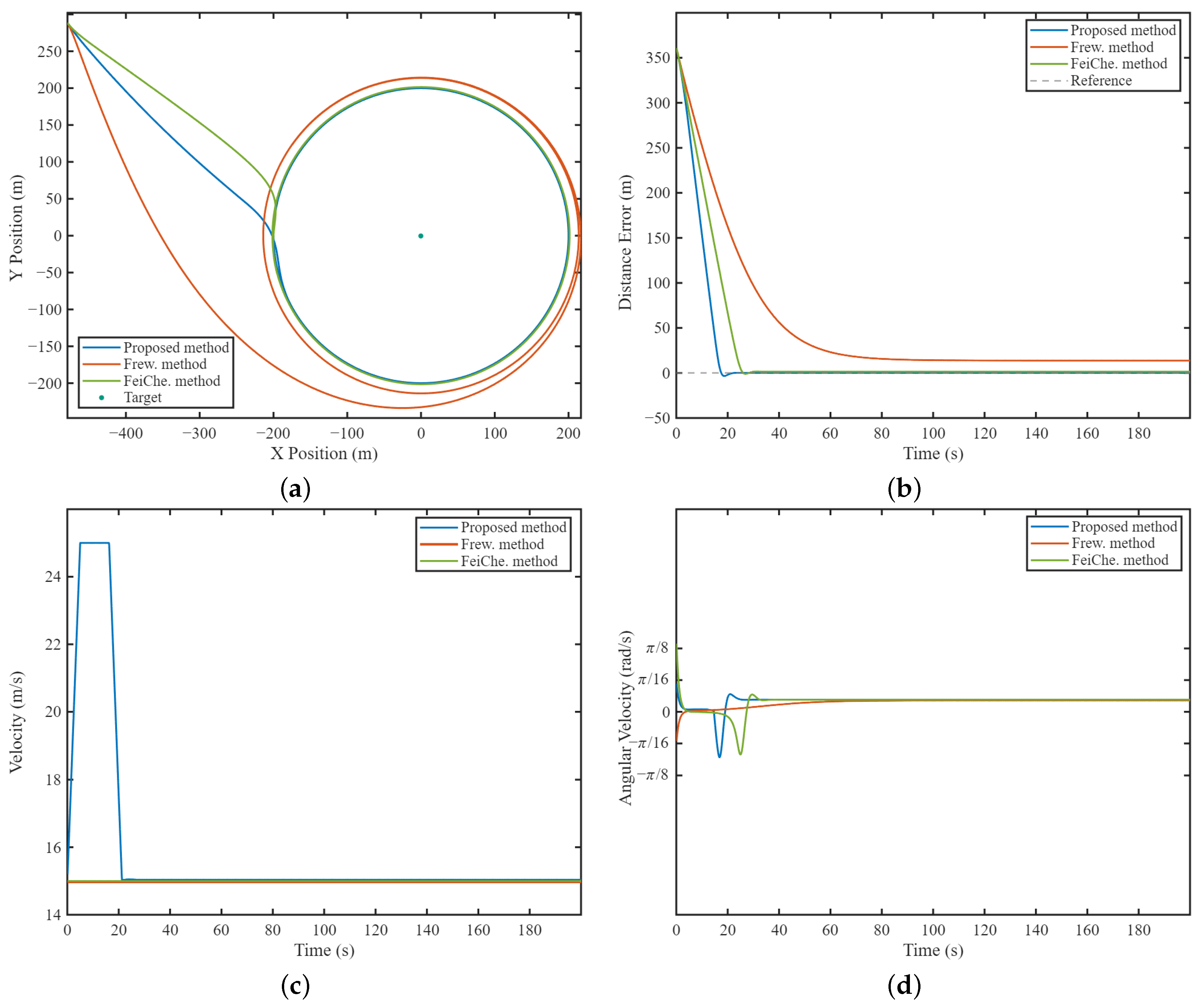
This simulation evaluates the convergence performance of the proposed algorithm for tracking a stationary target located at coordinates ( 0 , 0 ) . The UAVs were initially positioned at (−479.2, 288.7), with a heading of −45° and a speed of 15 m/s. The proposed method used control parameters K p = 0.8 and K i = 0.005 , while the Frew method required no tuning, and the FeiChe method used a control parameter of c = 0.3 . As shown in Figure 9a, the proposed algorithm achieved faster convergence to the desired standoff radius ( R = 200 m) compared to both the Frew and FeiChe methods. Quantitative analysis presented in Figure 9b indicates the convergence times for each algorithm to reach within ± 2 m of their respective final steady-state values: 20.1 s for the proposed method, 79.1 s for the Frew method, and 27.8 s for the FeiChe method. This improvement is attributed to two principal design features: first, the proposed method dynamically adjusts the UAVs’ velocity based on real-time proximity to the standoff circle, as shown in Figure 9c, optimizing trajectory planning during the approach phase; second, it demonstrates enhanced angular velocity control, as shown in Figure 9d, enabling tighter maneuvers near the target. Steady-state distance errors further confirm the superiority of the proposed approach, with a mean error of 0.014 m, compared to the Frew method’s mean error of 13.8 m and the FeiChe method's mean error of 1.422 m. This precision is attributed to the integral term in the approach velocity component, which effectively mitigates the steady-state errors present in existing methods.

5.1.2. Phase-Synchronized Cooperative Tracking of Maneuvering Target

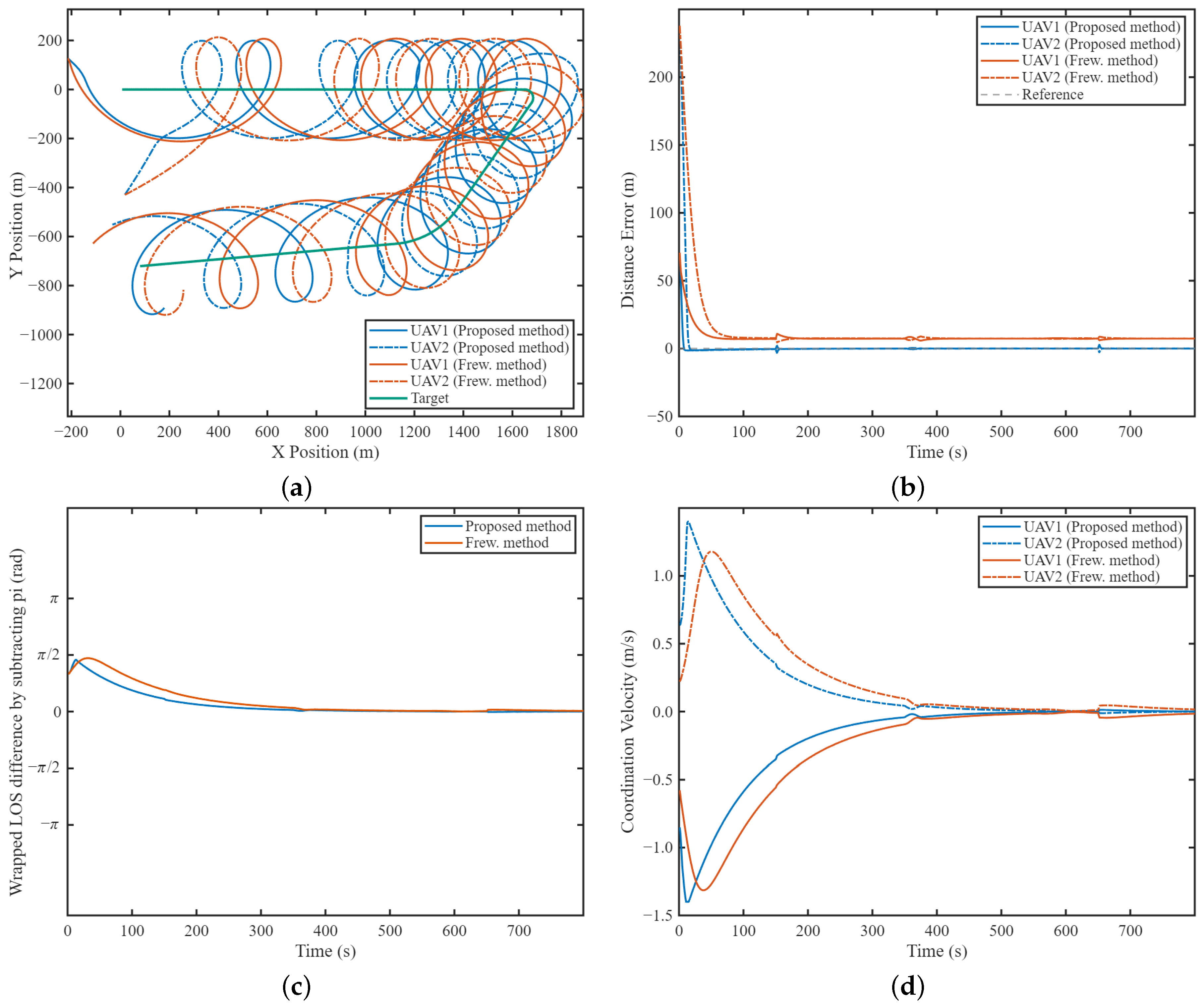
This experiment evaluated the cooperative tracking capabilities of the proposed algorithm. UAV 1 and UAV 2 started at positions ( 227.7 , 134.8 ) and ( 3.4 , 438.0 ) , respectively, each with an initial heading of 0° and a speed of 15 m/s. The maneuver of the target involved sudden accelerations, decelerations, and both sharp and gentle turns, as shown in Figure 8. The proposed method employed a 1 , 2 = 1 and a 2 , 1 = 1 for coordination velocity, while the Frew method utilized k = 1 . Both algorithms successfully converged to the desired standoff radius. As illustrated in Figure 10b, a comparison of distance error fluctuations during target maneuvers was conducted, with the results summarized in Table 4. The comparison indicates that the proposed method generally outperformed the others in reducing maneuver-induced distance errors.
Addictionly, Figure 10a shows that both algorithms converged to the standoff radius with a 180° phase separation. Figure 10c indicates that the phase difference convergence time, defined as the time taken to reach 5% of the initial phase difference, was 329 s for the proposed method and 367 s for the compared method. Figure 10d attributes this difference to the more aggressive velocity adjustment of the proposed method.

5.1.3. Occlusion-Robust Tracking with Dynamic Role Transition

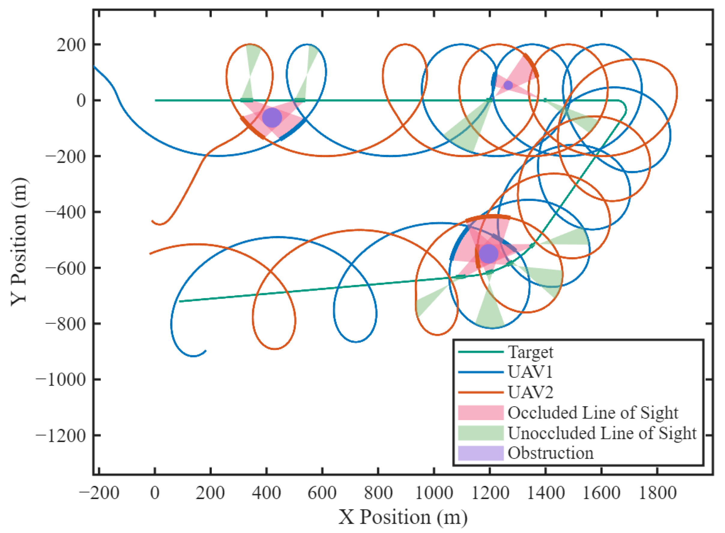
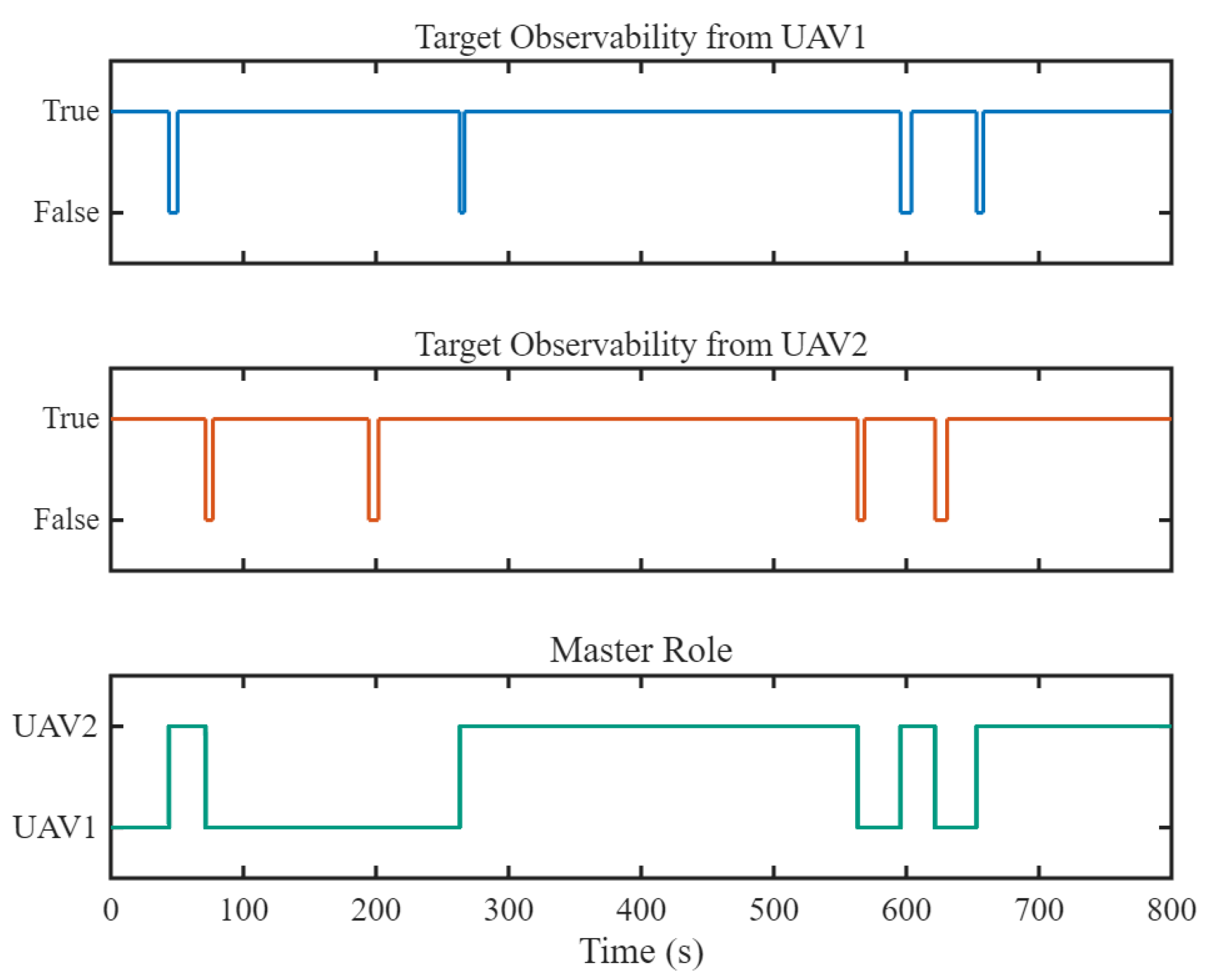
Building on the setup in Section 5.1.2, three cylindrical obstructions are introduced: Obstruction 1, centered at ( 1195.9 , 550.1 ) , with a radius of 34.7 m; Obstruction 2, at ( 1266.0 , 53.5 ) , with a radius of 16.6 m; and Obstruction 3, at ( 420.0 , 62.2 ) , with a radius of 35.8 m. Figure 11 shows the bold trajectory segment where the UAV’s LOS to the target was obstructed, corresponding to the red-marked region in the map. Meanwhile, another UAV could observe the target, with its LOS in the green-marked area. Figure 12 indicates that UAV1 was occluded between 44.2 and 50 s, 263.2 and 266.8 s, 595.4 and 604 s, and 653 and 658.2 s, while UAV2 was occluded between 71.4 and 77 s, 194.4 and 201.6 s, 563.2 and 568.4 s, and 621.6 and 630.8 s during the simulation. Despite the alternating occlusions, the role transition mechanism ensures continuous tracking via information sharing between UAVs. The results confirm that the proposed dual-layer framework effectively ensures standoff tracking for both UAVs, provided that neither is simultaneously obstructed.

5.2. Hardware-in-the-Loop Simulation

5.2.1. HIL Simulation Setup

To evaluate the proposed framework under more realistic conditions, we employed an HIL simulation to emulate real-world scenarios and validate the occlusion-robustness of our proposed method. The HIL system integrated FlightGear and PX4 on a desktop computer operating with Ubuntu 20.04. The CUAV V5+ served as the flight controller, while FlightGear 2020 simulated the external environment. The flight control unit operated on PX4 firmware version 1.13. The system included two UAVs simulated through HIL and a ground target simulated via software-in-the-loop (SIL) simulation.
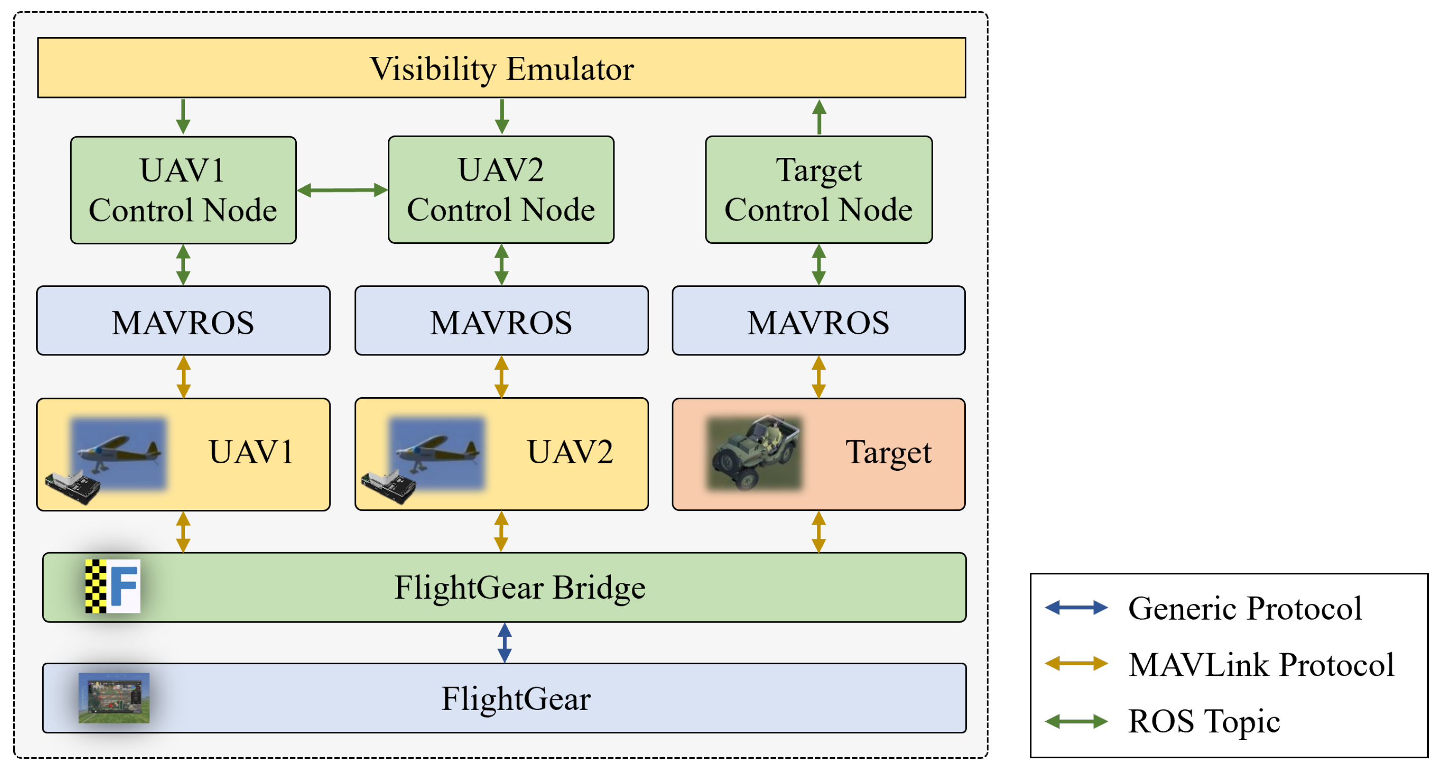
Figure 13 depicts the HIL simulation architecture, where the FlightGear simulator interfaced with PX4-based UAVs and a target via the FlightGear bridge middleware. This bridge ensured bidirectional communication, utilizing built-in User Datagram Protocol (UDP) ports for target interfacing and custom serial plugins for flight controller connections. This setup allowed UAVs and the target to receive simulated sensor data from FlightGear while sending actuator commands back to the simulator for dynamic motion portrayal. The architecture includes three control nodes—a UAV1 control node, UAV2 control node, and target control node—all linked using the Micro Air Vehicle Robot Operating System (MAVROS) for communication with their flight controllers. The UAVs’ control nodes employed the proposed framework for autonomous operations, whereas the target control node managed the target’s movement based on predefined motion profiles (as detailed in Figure 8). To replicate real-world sensing conditions, the visibility emulator module processed the target’s state data by introducing noise and intermittently disrupting data transmission. This simulates scenarios where UAVs lose visual or sensor-based tracking of the target, thereby enhancing the HIL environment’s realism. A screenshot of the HIL simulation interface, showing the real-time visualization of the UAVs and target in FlightGear, is presented in Figure 14.
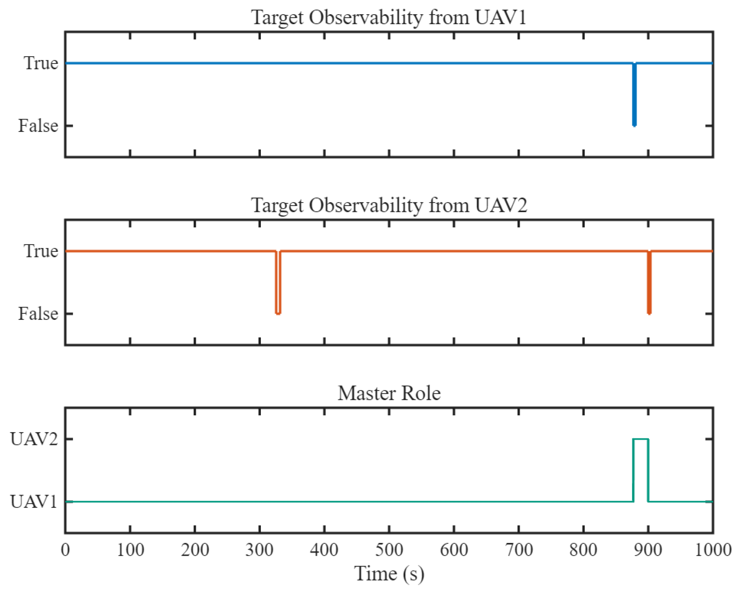
The visibility emulator module introduced Gaussian noise to the target’s position, velocity, and true heading to simulate real-world sensing conditions. Specifically, Gaussian noise with a mean ( μ ) of 0 and a standard deviation ( σ 2 ) of 6 affected the position, while the velocity and true heading were affected Gaussian noise with means of 0 and standard deviations of 1 and 0.07, respectively. Additionally, the module simulated sensing degradation due to occlusion by introducing periods of target states unavailability at predefined intervals, during which the UAVs could not access the target states. For instance, UAV1 lost the target observation from 877.1 to 880.0 s, while UAV2 lost the target observation from 325.6 to 331.45 s and again from 899.9 to 903.3 s. This allowed for the evaluation of the robustness of the proposed strategies under uncertain conditions.
The simulation employed the East-North-Up (ENU) coordinate system, with the ground target initially positioned at (0, 0) and stationary until 200 s. Subsequently, from 200 to 1000 s, the target moved with a specified velocity and heading, as depicted in Figure 8. Two UAVs took off from designated points: UAV1 from (−399, 1442) and UAV2 from (−399, 1535).

5.2.2. HIL Simulation Results

In the simulation settings described in Section 5.2.1, the impact of simulated occlusion and noise on the UAVs’ roles and tracking performance was examined. Figure 15 and Figure 16 illustrate these effects. When UAV2’s LOS was obstructed between 325.6 and 331.45 s, UAV1 retained its Master role, preventing any role transition. Conversely, between 877.1 and 880.0 s, when UAV1—the Master—experienced occlusion, the UAVs successfully exchanged roles. This demonstrates that occlusion in the Master UAV’s LOS can trigger a role transition based on the state-driven decision-making mechanism. Similarly, when UAV2’s LOS was obstructed between 899.9 and 903.3 s, the roles were swapped again, as UAV1 was the Master at that time.
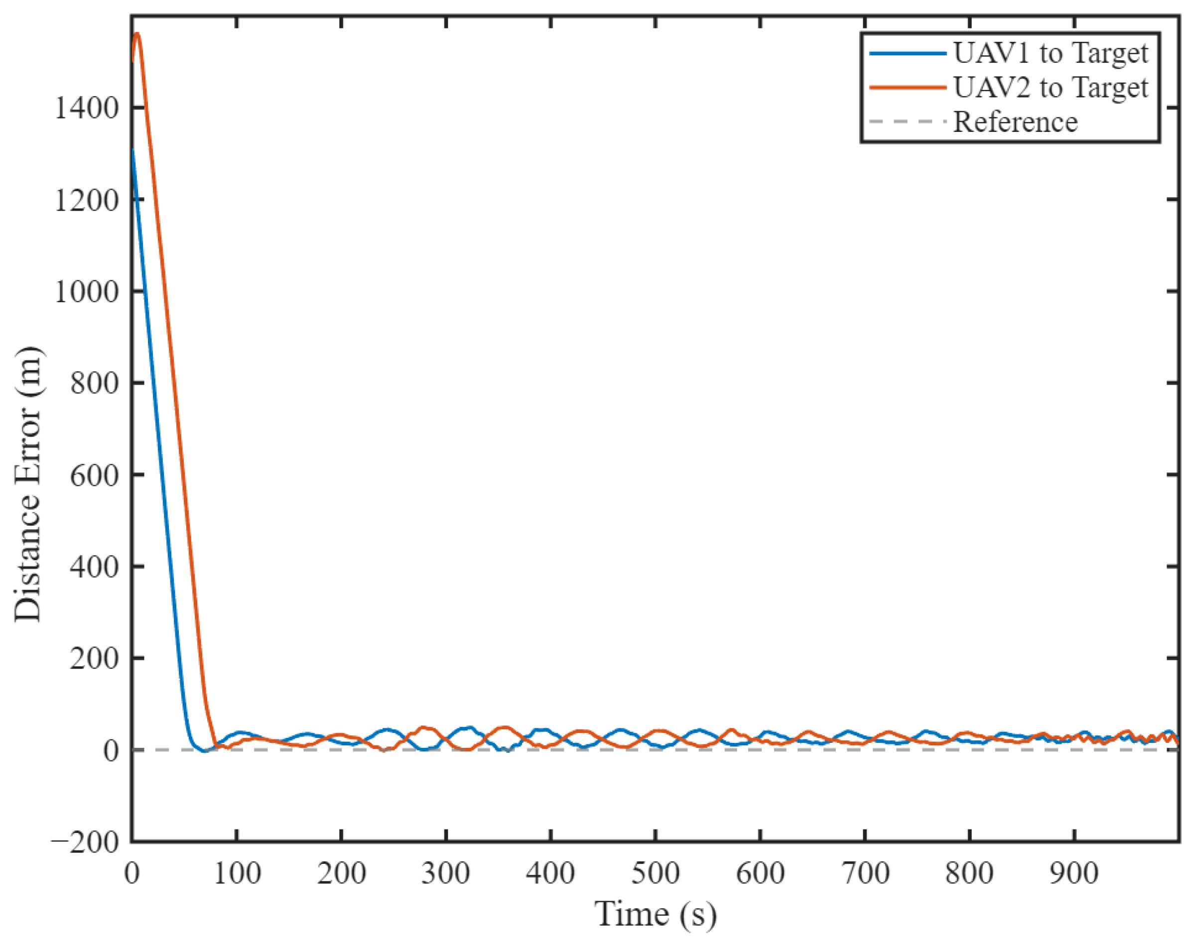
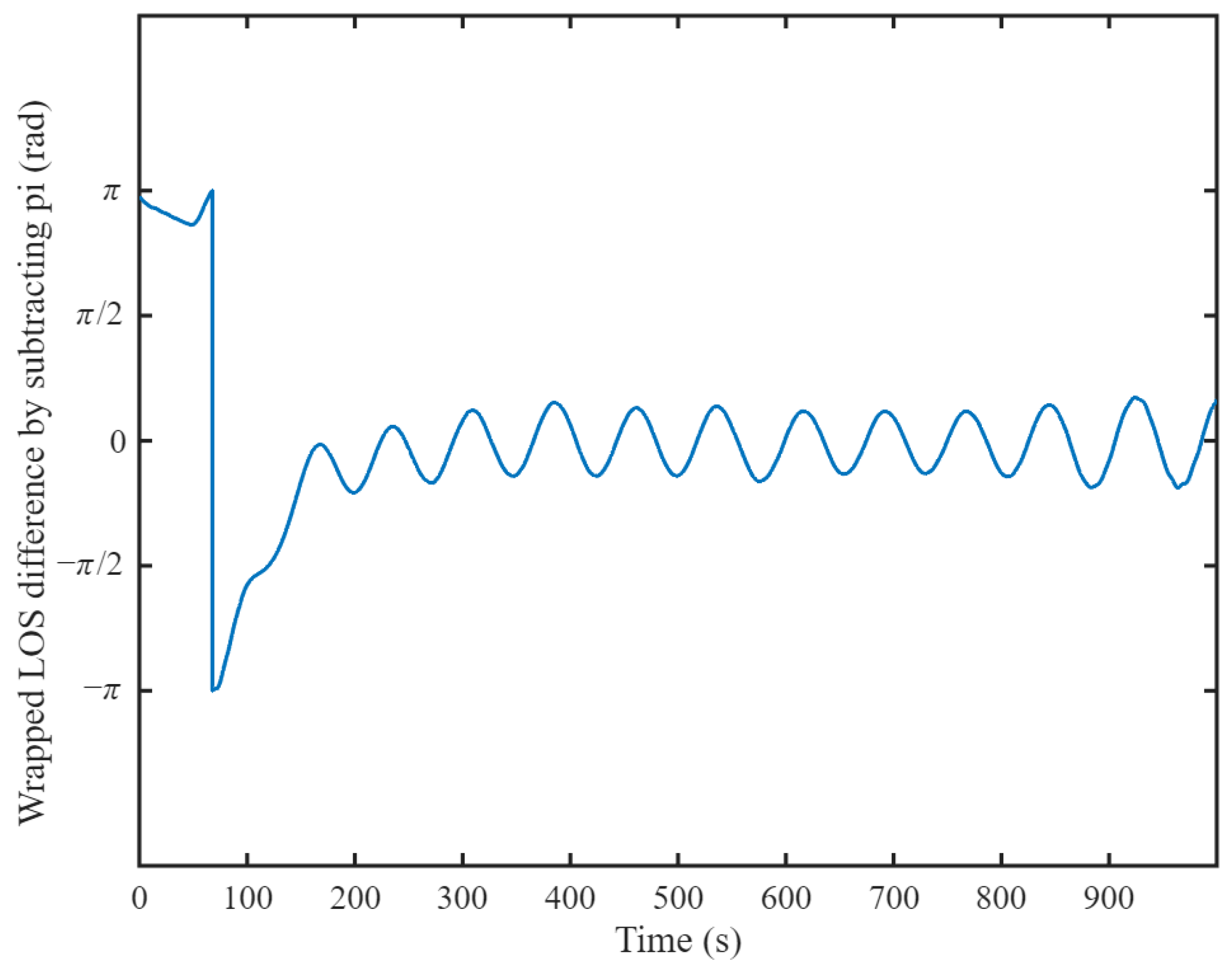
Figure 17 depicts the distance error between the UAVs, with a maximum error of approximately 48 m observed between 250 and 350 s. In contrast, between 800 and 1000 s, the distance error remained relatively low, ranging from 16 to 25 m. These findings suggest that although occlusion and noise adversely affected the tracking accuracy, the system maintained a satisfactory level of performance. Furthermore, Figure 18 presents the LOS difference between UAV1 and UAV2 after subtracting π and applying phase wrapping, where the value reached 180° at 163.8 s. Subsequently, the value converged to a range between 0.433 and 0.46 rad, exhibiting continued fluctuations over time. This variability implies that noise exerts a greater influence on phase difference measurements than on distance error, indicating that the system is more sensitive to noise in phase measurements than in distance calculations.

6. Conclusions

In this paper, we have proposed a dual-layer framework for cooperative standoff tracking of ground-moving targets using dual-UAV systems. Our approach addresses occlusion-induced tracking interruptions via a distributed state-transition role algorithm in the decision-making layer and a velocity-vector-based guidance law in the guidance layer. This framework allows seamless transition of Master-Slave roles during occlusion, maintaining a precise standoff distance and optimal phase separation. The Lyapunov analysis proved the asymptotic stability of both radial convergence and phase synchronization. The simulations demonstrated that the proposed framework significantly outperformed the benchmark methods in terms of convergence speed, steady-state accuracy.
Future research could focus on expanding the framework to multi-UAV systems ( n > 2 ) by integrating priority mechanisms into the role transition algorithm. These improvements may enhance system robustness during prolonged occlusions and preserve angular separation in more complex scenarios.

Author Contributions

Conceptualization, J.C. and D.Y.; methodology, J.C. and D.Y.; software, J.C.; validation, J.C., X.Y. and H.Z.; formal analysis, J.C. and H.C.; investigation, J.C. and L.L.; resources, D.Y., H.C. and J.F.; data curation, J.C.; writing—original draft preparation, J.C.; writing—review and editing, D.Y., J.F. and H.C.; visualization, J.C.; supervision, D.Y., H.C. and Y.C.; project administration, D.Y.; funding acquisition, D.Y. and H.C. All authors have read and agreed to the published version of the manuscript.

Funding

This work was supported by the National Natural Science Foundation of China (No. 62303483).

Data Availability Statement

The data supporting the conclusions of this article will be made available by the authors upon request.

Conflicts of Interest

The authors declare no conflicts of interest.

References

  1. Zhou, L.; Leng, S.; Liu, Q.; Wang, Q. Intelligent UAV Swarm Cooperation for Multiple Targets Tracking. IEEE Internet Things J. 2022, 9, 743–754. [Google Scholar] [CrossRef]
  2. Hayat, S.; Yanmaz, E.; Muzaffar, R. Survey on Unmanned Aerial Vehicle Networks for Civil Applications: A Communications Viewpoint. IEEE Commun. Surv. Tutor. 2016, 18, 2624–2661. [Google Scholar] [CrossRef]
  3. Zhang, Z.; Wang, Y.; Luo, Y.; Zhang, H.; Zhang, X.; Ding, W. Iterative Trajectory Planning and Resource Allocation for UAV-Assisted Emergency Communication with User Dynamics. Drones 2024, 8, 149. [Google Scholar] [CrossRef]
  4. Huang, Z.; Wu, W.; Wu, K.; Yuan, H.; Fu, C.; Shan, F.; Wang, J.; Luo, J. LI2: A New Learning-Based Approach to Timely Monitoring of Points-of-Interest With UAV. IEEE Trans. Mob. Comput. 2025, 24, 45–61. [Google Scholar] [CrossRef]
  5. Zhou, X.; Jia, W.; He, R.; Sun, W. High-Precision Localization Tracking and Motion State Estimation of Ground-Based Moving Target Utilizing Unmanned Aerial Vehicle High-Altitude Reconnaissance. Remote Sens. 2025, 17, 735. [Google Scholar] [CrossRef]
  6. Frew, E.W.; Lawrence, D.A.; Morris, S. Coordinated Standoff Tracking of Moving Targets Using Lyapunov Guidance Vector Fields. J. Guid. Control. Dyn. 2008, 31, 290–306. [Google Scholar] [CrossRef]
  7. Oh, H.; Kim, S. Persistent Standoff Tracking Guidance Using Constrained Particle Filter for Multiple UAVs. Aerosp. Sci. Technol. 2019, 84, 257–264. [Google Scholar] [CrossRef]
  8. Wang, X.; Liu, J.; Zhou, Q. Real-Time Multi-Target Localization from Unmanned Aerial Vehicles. Sensors 2017, 17, 33. [Google Scholar] [CrossRef]
  9. Yılmaz, C.; Ozgun, A.; Erol, B.A.; Gumus, A. Open-Source Visual Target-Tracking System Both on Simulation Environment and Real Unmanned Aerial Vehicles. In Proceedings of the 2nd International Congress of Electrical and Computer Engineering, Bandirma, Turkey, 22–25 November 2023; Seyman, M.N., Ed.; Springer: Cham, Switzerland, 2024; pp. 147–159. [Google Scholar]
  10. Liu, Z.; Xiang, L.; Zhu, Z. Cooperative Standoff Target Tracking Using Multiple Fixed-Wing UAVs with Input Constraints in Unknown Wind. Drones 2023, 7, 593. [Google Scholar] [CrossRef]
  11. Yao, P.; Wang, H.; Su, Z. Cooperative Path Planning with Applications to Target Tracking and Obstacle Avoidance for Multi-UAVs. Aerosp. Sci. Technol. 2016, 54, 10–22. [Google Scholar] [CrossRef]
  12. Fu, Y.; Xiong, H.; Dai, X.; Nian, X.; Wang, H. Multi-UAV Target Localization Based on 3D Object Detection and Visual Fusion. In Proceedings of the 3rd 2023 International Conference on Autonomous Unmanned Systems (3rd ICAUS 2023), Nanjing, China, 8–11 September 2023; Qu, Y., Gu, M., Niu, Y., Fu, W., Eds.; Springer: Singapore, 2024; pp. 226–235. [Google Scholar]
  13. Sun, T.; Cui, J. Multi-Agents Cooperative Localization with Equivalent Relative Observation Model Based on Unscented Transformation. Unmanned Syst. 2024, 12, 1063–1071. [Google Scholar] [CrossRef]
  14. Rao, K.; Yan, H.; Yang, P.; Wang, M.; Lv, Y. Multi-UAV Trajectory Planning with Field-of-view Sharing Mechanism in Cluttered Environments:Application to Target Tracking. Sci. China Inf. Sci. 2025, 68, 89–102. [Google Scholar] [CrossRef]
  15. Lawrence, D. Lyapunov Vector Fields for UAV Flock Coordination. In Proceedings of the 2nd AIAA “Unmanned Unlimited” Conference and Workshop & Exhibit, San Diego, CA, USA, 15–18 September 2003. [Google Scholar] [CrossRef]
  16. Chen, H.; Chang, K.; Agate, C.S. UAV Path Planning with Tangent-plus-Lyapunov Vector Field Guidance and Obstacle Avoidance. IEEE Trans. Aerosp. Electron. Syst. 2013, 49, 840–856. [Google Scholar] [CrossRef]
  17. Oh, H.; Kim, S.; Tsourdos, A.; White, B.A. Decentralised Standoff Tracking of Moving Targets Using Adaptive Sliding Mode Control for UAVs. J. Intell. Robot. Syst. 2013, 76, 169–183. [Google Scholar] [CrossRef]
  18. Lim, S.; Kim, Y.; Lee, D.; Bang, H. Standoff Target Tracking Using a Vector Field for Multiple Unmanned Aircrafts. J. Intell. Robot. Syst. 2013, 69, 347–360. [Google Scholar] [CrossRef]
  19. Pothen, A.A.; Ratnoo, A. Curvature-Constrained Lyapunov Vector Field for Standoff Target Tracking. J. Guid. Control. Dyn. 2017, 40, 2729–2736. [Google Scholar] [CrossRef]
  20. Sun, S.; Wang, H.; Liu, J.; He, Y. Fast Lyapunov Vector Field Guidance for Standoff Target Tracking Based on Offline Search. IEEE Access 2019, 7, 124797–124808. [Google Scholar] [CrossRef]
  21. Hu, C.; Zhang, Z.; Tao, Y.; Wang, N. Decentralized Real-Time Estimation and Tracking for Unknown Ground Moving Target Using UAVs. IEEE Access 2019, 7, 1808–1817. [Google Scholar] [CrossRef]
  22. Sun, S.; Liu, Y.; Guo, S.; Li, G.; Yuan, X. Observation-Driven Multiple UAV Coordinated Standoff Target Tracking Based on Model Predictive Control. Tsinghua Sci. Technol. 2022, 27, 948–963. [Google Scholar] [CrossRef]
  23. Zhu, Q.; Zhou, R.; Dong, Z.N.; Li, H. Coordinated Standoff Target Tracking Using Two UAVs with Only Bearing Measurement. J. Beijing Univ. Aeronaut. Astronaut. 2015, 41, 2116–2123. [Google Scholar] [CrossRef]
  24. Yang, Z.Q.; Fang, Z.; Li, P. Cooperative Standoff Tracking For Multi-UAVs Based on tau Vector Field Guidance. J. Zhejiang Univ. Eng. Sci. 2016, 50, 984. [Google Scholar] [CrossRef]
  25. Park, S.; Deyst, J.; How, J. A New Nonlinear Guidance Logic for Trajectory Tracking. In Proceedings of the AIAA Guidance, Navigation, and Control Conference and Exhibit, Austin, TX, USA, 16 August 2004; American Institute of Aeronautics and Astronautics: Reston, VA, USA, 2004. [Google Scholar] [CrossRef]
  26. Park, S.; Deyst, J.; How, J.P. Performance and Lyapunov Stability of a Nonlinear Path Following Guidance Method. J. Guid. Control. Dyn. 2007, 30, 1718–1728. [Google Scholar] [CrossRef]
  27. Huang, S.; Lyu, Y.; Zhu, Q.; Su, L.; Li, K.; Shi, J. UAV Fast Standoff Tracking of a Moving Target Based on a Composite Guidance Law. In Proceedings of the 2024 36th Chinese Control and Decision Conference (CCDC), Xi’an, China, 25–27 May 2024; pp. 1358–1363. [Google Scholar] [CrossRef]
  28. Wang, Y.; Shan, M.; Wang, D. Motion Capability Analysis for Multiple Fixed-Wing UAV Formations with Speed and Heading Rate Constraints. IEEE Trans. Control Netw. Syst. 2020, 7, 977–989. [Google Scholar] [CrossRef]
  29. Che, F.; Niu, Y.; Li, J.; Wu, L. Cooperative Standoff Tracking of Moving Targets Using Modified Lyapunov Vector Field Guidance. Appl. Sci. 2020, 10, 3709. [Google Scholar] [CrossRef]
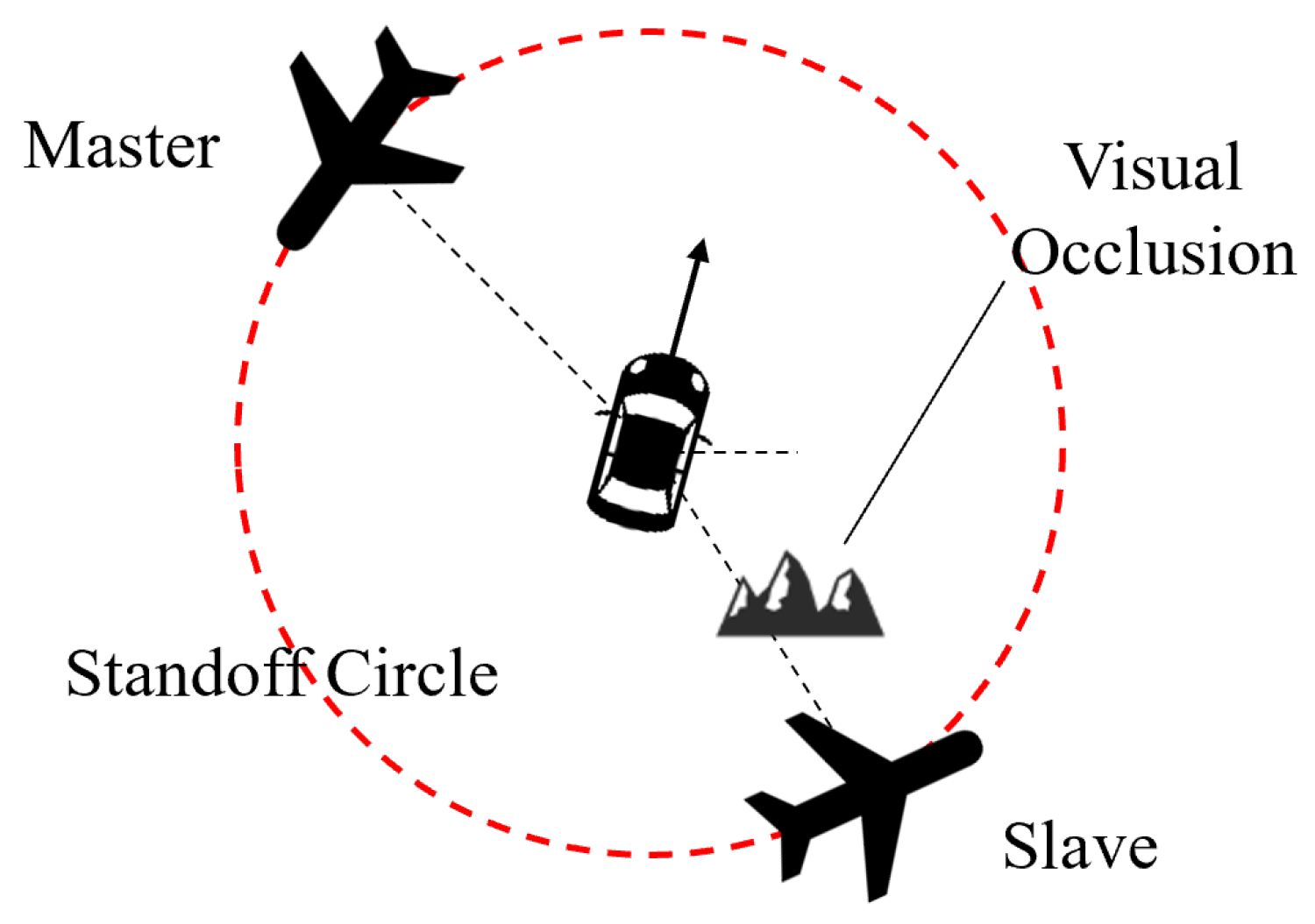
Figure 1. Dual-UAV cooperative tracking with occlusion from a single UAV.
Drones 09 00560 g001
Figure 2. Master–Slave collaborative target tracking with two observation modes.
Drones 09 00560 g002
Figure 3. Scenario of dual-UAV standoff tracking.
Drones 09 00560 g003
Figure 4. Dual -UAV standoff tracking architecture diagram.
Drones 09 00560 g004
Figure 5. Diagram of Master–Slave role transition.
Drones 09 00560 g005
Figure 6. Velocity analysis of dual-UAV standoff tracking.
Drones 09 00560 g006
Figure 7. Velocity vector field visualization: (a) counterclockwise; (b) clockwise.
Drones 09 00560 g007
Figure 8. Speed and heading of the moving target over time.
Drones 09 00560 g008
Figure 9. Comparison of tracking performance for stationary targets with the methods in [6,29]. (a) Trajectories of UAVs and target. (b) Standoff distance error. (c) Velocity of UAVs. (d) Angular velocity of UAVs.
Drones 09 00560 g009
Figure 10. Comparison of tracking performance for moving targets with the methods in [6]. (a) Trajectories of UAVs and target. (b) Standoff distance error. (c) Wrapped LOS difference by subtracting π . (d) Coordination velocity of UAVs.
Drones 09 00560 g010
Figure 11. Trajectories of UAVs and target.
Drones 09 00560 g011
Figure 12. Master–Slave transition under occlusions.
Drones 09 00560 g012
Figure 13. System architecture of the HIL simulation.
Drones 09 00560 g013
Figure 14. Screenshot of the simulation system interface.
Drones 09 00560 g014
Figure 15. Trajectories of UAVs and target.
Drones 09 00560 g015
Figure 16. Master–Slave transition under occlusions.
Drones 09 00560 g016
Figure 17. Standoff distance error.
Drones 09 00560 g017
Figure 18. Wrapped LOS difference by subtracting π .
Drones 09 00560 g018
Table 1. Functional modules of the two-layer framework.
LayerModuleFunction
Decision-Making LayerObservability ValidationEvaluates target state validity; flags observation failure if no data received for >0.5 s
Role TransitionMaintains current/previous states to execute role transition algorithm
Data StorageAcquires target states via visual-inertial localization or inter-UAV comms
Transmission/ReceptionManages target states exchange between UAVs per Section 2.1
Guidance LayerVelocity Vector OperationsPerforms velocity vector synthesis
Control Input TranslatorConverts vector speeds to executable flight commands
Table 2. State transition decision table.
s ( 1 , t ) s ( 1 , t 1 ) s ( 2 , t ) s ( 2 , t 1 ) D ( Φ )
00112
01102
01112
10011
10112
11001
11011
11101
11110
Note: Unlisted state combinations return −1.
Table 3. Comparison of mobility performance between UAVs and target.
ParameterTargetUAVs
Speed (m/s)0–87–23
Acceleration (m/s2)≤10≤2
Yaw rate (°/s)≤10≤5
Table 4. Comparative distance error performance during target maneuvers.
Time (s)Target ManeuverMethodUAV1 Error (m)UAV2 Error (m)
150DecelerationProposed2.362.82
Frew et al. [6]3.863.11
350Sharp turnProposed0.750.72
Frew et al. [6]2.722.74
550Gentle turnProposed<0.2<0.2
Frew et al. [6]<0.2<0.2
650AccelerationProposed2.882.88
Frew et al. [6]1.381.48
Disclaimer/Publisher’s Note: The statements, opinions and data contained in all publications are solely those of the individual author(s) and contributor(s) and not of MDPI and/or the editor(s). MDPI and/or the editor(s) disclaim responsibility for any injury to people or property resulting from any ideas, methods, instructions or products referred to in the content.