1. Introduction
Global navigation satellite systems (GNSSs) are essential infrastructures for providing space-time services in modern society. However, during emergencies such as natural disasters or other critical scenarios, GNSS signals may become unavailable due to obstructions, interference, or system failures, highlighting the urgent need for backup navigation solutions to ensure reliable positioning and timing. Low-earth orbit (LEO) satellites and air-based platform navigation enhancement technologies are important means to improve GNSS navigation performance [
1,
2]. Compared with navigation enhancement using LEO satellite platforms, air-based platforms offer advantages such as high manoeuvrability, flexible deployment, strong regional dwelling capability, and stronger navigation signal reception power, showing greater application potential in regional navigation enhancement. High-altitude platforms such as stratospheric pseudolites have also demonstrated long service duration and flexible geometry control, further extending the applicability of aerial pseudolite systems to persistent or energy-sensitive environments [
3]. Recent studies on UAV-based air–ground cooperative navigation have demonstrated their effectiveness in GPS-denied environments by integrating aerial perception with mobile anchor localization [
4]. In particular, UAV-mounted pseudolite systems serve as agile, deployable signal sources, providing ground users with real-time positioning support and ensuring continuity of navigation services when GNSS signals are unavailable. Tsujii et al. [
5] conducted ground positioning experiments using helicopters to broadcast pseudolite signals and achieved decimeter-level carrier ranging accuracy by combining double-difference processing of ground pseudolite signals. Chen et al. [
6] proposed a wireless clock synchronization method based on carrier-phase observations for distributed pseudolite systems, offering potential application value for ensuring timing consistency in the practical implementation of air-based pseudolite systems. Oktay and Stepaniak [
7] studied the use of airborne pseudolites to improve navigation availability and accuracy in urban environments and demonstrated that the navigation availability time could be significantly increased from 28.6% to 71.7% through the reasonable addition of airborne pseudolites, highlighting the advantages of air-based pseudolites in complex regional environments.
Air-based platform navigation enhancement essentially uses aerial platforms such as unmanned aerial vehicles (UAVs) as navigation signal transmitters and broadcasts navigation signals during platform motion to provide navigation and positioning services to users independently or jointly with the GNSS. The design of air-based platform navigation signals and messages is one of the key technologies for achieving air-based platform navigation positioning and GNSS navigation enhancement. Ahmad et al. [
8] proposed a distance estimation method based on air-based platform signal strength (RSSI) at the user end, and Moon and Youn [
9] researched UAV swarm navigation and positioning on the basis of ultrawideband (UWB) signals. Limited by the signal strength and inherent characteristics of UWB signals, these navigation and positioning methods have limited service capabilities, with service area radii of only tens of metres. To improve air-based platform navigation service capabilities. Zhu et al. [
10] proposed a pseudonoise (PN) code-based self-positioning ranging code design method for UAV swarms. Ganguly et al. [
11] proposed improved navigation message formats to enhance navigation signal reliability using pseudolites. Wang [
12] designed pseudolite system deployment schemes based on air-based platform carrier types (such as aircraft, airships, or balloons) and motion characteristics. Additionally, Yang et al. [
13] proposed a space-based pseudolite deployment method that systematically minimizes GDOP, demonstrating superior robustness and positioning accuracy compared to empirical and heuristic algorithms. While these studies have made significant progress in improving air-based platform navigation performance, they require specialized navigation signal broadcasting and receiving equipment matched to air-based platform motion and navigation signal design, cannot achieve sharing with GNSS navigation equipment, and need to be designed according to application scenarios.
To improve the compatibility between air-based platform navigation and GNSS, some scholars have conducted research on the adaptive application of satellite navigation messages in air-based platform pseudolite systems. Farley and Carlson [
14] proposed a navigation message design method for non-Keplerian motion mobile platforms, but their research focused mainly on stationary pseudolites, showing limitations when applied to dynamic air-based platforms. Tuohino et al. [
15] designed a pseudolite system and navigation message format for military application scenarios combined with UAV motion, but since it changed the original message parameter structure within each subframe, corresponding modifications to receiver positioning algorithms were required during application, increasing system complexity. Kim et al. [
16] fully considered the special motion characteristics of air-based platforms and designed dedicated navigation message formats for typical motion modes of airborne platforms, but since their message format remained incompatible with standard GNSS receivers, GNSS receivers could not be reused for signal reception, message parsing, and positioning calculations. These studies have provided new ideas for air-based platform navigation message design and achieved satellite navigation message adaptation applications on air-based platforms to some extent, but further improvements are still needed in platform motion mode coverage and navigation message reuse degree. They have not fully achieved complete adaptation of GNSS navigation messages to air-based platform motion, and practical applications still require modifications to existing GNSS hardware or software, limiting their application potential.
The ability of air-based platforms to broadcast navigation messages fully compatible with the GNSS and use these messages to accurately characterize and calculate platform positions is fundamental to achieving air-based platform-based navigation and positioning without changing GNSS signal broadcasting and receiver structures. However, GNSS navigation messages are primarily used to characterize and predict GNSS satellite orbital motion. Unlike GNSS satellites, which satisfy perturbed two-body mechanics models, air-based platforms experience more complex forces and have strong manoeuvrability and variable motion trajectories, making the use of GNSS navigation messages to describe air-based platform motion highly challenging. Currently, there are no published research results domestically or internationally on directly and effectively using GNSS navigation message formats for air-based platforms to characterize their positions and motion. Although some efforts have been made to utilize machine learning techniques to model the trajectory behavior of UAV pseudolite platforms, such as the ephemeris learning method based on deep networks proposed by Liu et al., these approaches still rely heavily on data-driven fitting and cannot ensure structural compatibility with standard GNSS navigation message formats, thus limiting interoperability with existing GNSS receivers [
17].
Building upon GNSS navigation message structures, this study proposes an innovative method for encoding air-based platform motion directly into GNSS-compatible ephemeris parameters. This design enables the reuse of standard GNSS receivers without modification, allowing airborne navigation enhancement platforms to function as motion-adaptive signal emitters within existing satellite sensing frameworks. This paper refers to the proposed method as UAV-based Adaptive Positioning via Ephemeris (UAPE), which forms the core of the signal design and adaptation strategy. As a result, UAPE improves navigation and positioning performance in complex regional environments while maintaining full compatibility with sensor-side processing pipelines.
While the reuse of GNSS-compatible signals raises concerns over co-frequency interference and regulatory compliance, this method does not imply full replication of existing GNSS signals. Instead, it proposes the construction of independent broadcast signals using GNSS message-compatible structures, with custom Pseudo-Random Noise (PRN) number codes and frequency separation to avoid interference with active GNSS systems.
Previous studies, such as those by Ge et al. [
18], have demonstrated the feasibility of signal coexistence via proper frequency planning and system isolation. Furthermore, Schmidt [
19] verified that directional antenna design can suppress interference by 20–50 dB when signal paths differ, further supporting the practical deployment of such airborne emitters within multi-source GNSS sensing environments.
The remainder of this paper is organized as follows.
Section 2 presents the theoretical models and methods, including satellite orbit representation, message parameter formulation, and the proposed ephemeris adaptation framework for airborne platforms.
Section 3 details the simulation-based evaluation of the proposed method under various motion scenarios, with an analysis of the resulting positioning errors and their influencing factors.
Section 4 provides experimental validation using UAV flight tests, focusing on message generation and receiver-side performance under real-world conditions.
2. UAV-Based Adaptive Positioning via Ephemeris (UAPE)
This chapter first compares existing pseudolite ephemeris construction mechanisms with the proposed UAPE method, followed by a detailed description of UAPE’s theoretical foundation, algorithm workflow, and higher-order correction strategies.
2.1. Comparison Between UAPE and Existing Techniques
Table 1 presents the key differences between UAPE and existing pseudolite ephemeris construction mechanisms. Compared to traditional methods, the UAPE algorithm fully considers the dynamic characteristics of UAV platforms and achieves high-precision, low-bandwidth navigation information transmission through adaptive parameter fitting and higher-order correction strategies.
As summarized in
Table 1, the proposed UAPE method departs fundamentally from conventional pseudolite methods [
9,
10,
11,
14] in both architectural and functional design. Traditional systems often require non-standard GNSS message structures and dedicated pseudolite hardware, limiting their interoperability and increasing deployment complexity. In contrast, UAPE operates fully within the 18-parameter standard GNSS navigation message format and reuses existing receiver hardware without modification.
In terms of motion adaptability, previous solutions were primarily designed for static or low-dynamic environments [
12,
20], rendering them ineffective in high-mobility UAV applications. UAPE addresses this gap by enabling accurate ephemeris generation across a wide range of motion conditions, including high-speed, uniform flight. It also facilitates enhanced integration with GNSS/RTK systems, allowing joint positioning solutions—an area where earlier methods [
4,
5] have shown limited applicability.
From an engineering perspective, UAPE significantly reduces system complexity by eliminating the need for custom message formats or decoding logic. Instead, it leverages standardized GNSS parsing mechanisms to simplify both transmitter design and receiver-side integration. This balance of compatibility, scalability, and motion adaptability enables UAPE to support airborne navigation enhancement in complex operational environments where earlier pseudolite-based approaches break down.
2.2. Satellite Navigation Ephemeris Parameters and Position Calculation
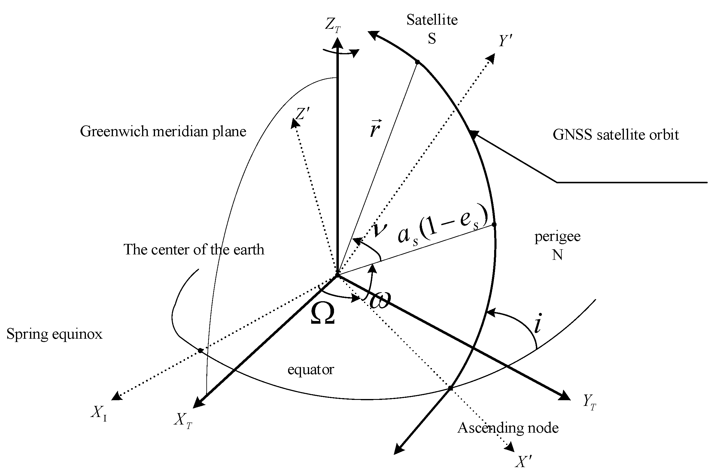
Ephemeris parameters are important information in GNSS navigation messages and are used primarily to describe GNSS satellite orbital motion and calculate satellite positions. These methods include time, six satellite orbital elements and their perturbation corrections [
21]. The orbital elements include the semimajor axis (
), eccentricity (
), orbital inclination (
), right ascension of the ascending node (
), argument of the perigee (
), and true anomaly (
), as shown in
Figure 1 [
22,
23].
Currently, commonly used ephemeris parameter models in GNSS navigation messages include the 16-parameter model [
24] and the 18-parameter model [
25].
Table 2 lists the specific composition of the 18-parameter model, while the 16-parameter model lacks the final two parameters (
,
), which limits its ability to describe orbital dynamic changes, particularly in highly dynamic and long-duration situations.
In GNSS navigation and positioning applications, users receive navigation ephemeris parameters and calculate satellite positions, combining navigation observables such as the pseudorange and carrier phase to achieve positioning solutions at the user end. The formula for calculating the satellite position in the Earth-fixed coordinate system at time t using ephemeris parameters is as follows:
where
represents the corrected orbital radius,
represents the reference value of the semimajor axis,
represents the corrected latitude argument,
represents the corrected longitude of the ascending node,
represents the Earth’s rotation rate,
represents the corrected orbit inclination,
represents the true anomaly, which is converted from the mean anomaly
,
represents the Earth’s gravitational constant, and
represents the perturbation correction terms, all of which are functions of
:
In air-based platform navigation and positioning, platform motion characterization and position calculation similarly rely on air-based platform ephemeris parameters. If air-based platforms can directly reuse satellite navigation message parameters, that is, use GNSS navigation messages for air-based platform motion characterization, then GNSS receivers can be directly applied for air-based platform navigation and positioning without requiring software and hardware adaptive modifications. The next section introduces the design method for satellite navigation message parameter adaptation to air-based platforms.
2.3. Navigation Ephemeris Parameter Adaptation Method for Air-Based Platforms
GNSS satellite navigation ephemeris parameters are designed primarily for medium- and high-orbit navigation satellites. The coordinate reference and motion characteristics of air-based platforms differ significantly from those of navigation satellites, preventing direct use for characterizing air-based platform position and motion. Through reference transformation, parameter mapping, and error correction processing, satellite navigation message parameter adaptation applications on air-based platforms can be achieved. The core lies in utilizing perturbation corrections in ephemeris parameters to describe position changes in air-based platforms. The following sections introduce parameter adaptation for initial position of the air-based platform and motion process characterization with model adaptation.
2.3.1. Adaptation of Air-Based Platform Initial Position Parameters
The coordinate transformation of the initial position of the air-based platform and ephemeris parameter adaptation are the primary steps in achieving GNSS navigation message parameter characterization of air-based platform motion and position calculation. This is accomplished mainly by constructing a virtual reference ellipsoid coordinate system and applying coordinate transformation and parameter mapping to characterize the ephemeris parameters of the initial position of the air-based platform in the geodetic coordinate system.
(1) Coordinate Transformation between Air-based Platform Geodetic Coordinates and Virtual Reference Ellipsoid
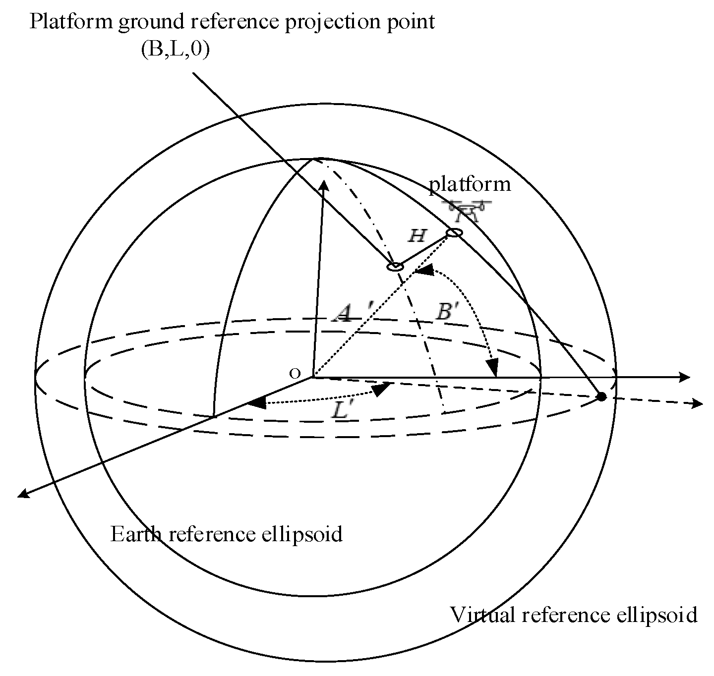
Since message parameters are primarily used to calculate satellite positions in the inertial coordinate system, while the air-based platform position and velocity are described mainly in the geodetic coordinate system, considering the difference in spatial references between the two, a virtual reference ellipsoid is constructed to assist in achieving platform coordinate transformation and parameter adaptation. The virtual reference ellipsoid is defined as follows: on the basis of the Earth reference ellipsoid, proportionally enlarged to the ellipsoid where the air-based platform is located becomes the air-based platform virtual reference ellipsoid.
Let the geodetic coordinates of the initial position of the air-based platform be
and the coordinates of the initial position of the air-based platform in the virtual reference ellipsoid coordinate system be
, where
,
, and
represent the geographic latitude, longitude, and altitude, respectively, and
represent the geographic latitude, longitude, and semimajor axis, respectively, in the reference ellipsoid coordinate system. The coordinate transformation relationships between the geodetic coordinate system and the virtual reference ellipsoid are illustrated in
Figure 2 and can be expressed as follows:
where
represents the radius of curvature in the prime vertical direction, and e represents the first eccentricity of the Earth, satisfying the following equation:
(2) Mapping between Air-based Platform Reference Ellipsoid Coordinates and Ephemeris Parameters
After completing the coordinate transformation between the air-based platform geodetic coordinates and the virtual reference ellipsoid coordinates, the mapping relationship between the air-based platform reference ellipsoid coordinates and ephemeris parameters is further constructed to characterize the ephemeris parameters of the initial position of the air-based platform.
In the 18-parameter ephemeris model, the position-related parameters include orbital inclination
, the right ascension of the ascending node
, the semimajor axis
, and their corrections. To maintain the initial position coordinates of the air-based platform unchanged, the orbital inclination and right ascension of the ascending node should be time-independent constants. Therefore, the rate of change in the right ascension of the ascending node
and the rate of change in the orbital inclination di/dt should satisfy the following relationship:
where
is the Earth’s rotation rate.
Assuming that the position of the air-based platform is represented with respect to a virtual reference ellipsoid, its instantaneous location
can be mapped to a set of ephemeris parameters defining a virtual reference elliptical orbit. At the initial reference time
, the mapping relationship between the platform’s virtual ellipsoidal coordinates and the broadcast message parameters
is given by:
where
is the longitude of the ascending node of the virtual reference elliptical orbit and where
is the mean radius of the Earth.
Through the construction of the virtual reference ellipsoid and air-based platform coordinate transformation described above, message parameter adaptation of the initial position of the air-based platform is achieved, providing initial conditions for air-based platform motion trajectory characterization.
2.3.2. Parameter Adaptation for Air-Based Platform Motion Trajectory
The analysis of air-based platform motion characteristics and the construction of motion models form the foundation for achieving satellite navigation message characterization of platform motion trajectories and adaptation applications. Compared with satellites, air-based platforms experience more complex force environments and highly dynamic motion variations. The motion trajectory characterization of air-based platforms using position, velocity, and acceleration parameters is shown as follows:
where
and
are the platform position vectors at times
and
, respectively, and where
and
represent velocity and acceleration vectors, respectively. To balance motion model accuracy and computational complexity, piecewise linearization of the platform motion model is performed, approximating the air-based platform motion within consecutive navigation message broadcast periods as uniform linear motion, expressed as follows:
where
and
are the (k − 1)th and kth navigation message broadcast times, respectively, and where
represents the message broadcast time interval.
From the analysis in the previous section, characterizing the ephemeris parameters of air-based platform motion primarily involves describing changes in
through the design of
,
and
along with their perturbation parameters, thereby characterizing the air-based platform motion trajectory. To this end, Taylor expansion of the message parameters is first performed at the reference point. Taking the right ascension of the ascending node
as an example, its Taylor expansion at the air-based platform position at time k − 1 is as follows:
where
represents the right ascension of the ascending node at the message broadcast time,
is the gradient vector of
with respect to
at the reference point,
is the Hessian matrix of
at the reference point, and
represents the position increment during platform motion. Combining Equation (9) to calculate the first-order change quantity
of
and provide its relationship with the message parameter
is as follows:
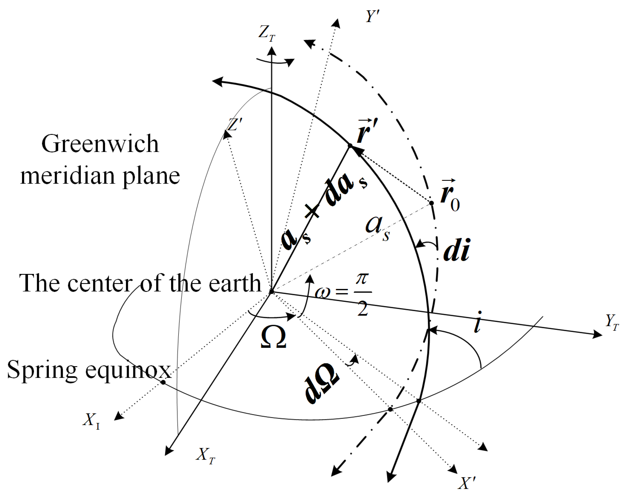
where the first-order parameter change rate reflects the message parameter perturbations caused by position increments around the message broadcast time position during air-based platform motion.
Figure 3 illustrates the physical meaning of the first-order corrected message parameters.
On the basis of Equation (10), by calculating the air-based platform position increment to compute the first-order rate of change in the ephemeris parameters, the first-order perturbation terms of each ephemeris parameter in the navigation message under uniform motion can be obtained, achieving navigation ephemeris parameter adaptation for air-based platform motion trajectories.
2.4. Navigation Ephemeris Parameter Adaptation Error Analysis and Correction
According to the analysis in the previous section, using ephemeris parameters for air-based platform motion characterization involves two main types of errors: first, ephemeris parameters consider only first-order term parameter mapping in Taylor expansion analysis and subsequent formula derivation, resulting in higher-order term truncation errors; second, air-based platform motion is assumed to be piecewise uniform motion and modelled accordingly, resulting in model assumption errors. In particular, when the air-based platform acceleration significantly changes, decreased model accuracy leads to increased message parameter adaptation errors. To improve the accuracy of the characterization of the navigation ephemeris parameters, this section focuses on studying ephemeris parameter higher-order error correction and the influence of the navigation message broadcast frequency on the motion model.
2.4.1. Impact of Higher-Order Terms on Errors and Correction
In
Section 2.3, a mapping relationship between the ephemeris parameters
,
, and
and the air-based platform position is established, and first-order Taylor expansion is used to characterize platform motion. However, when the air-based platform motion time extends or the velocity increases, retaining only first-order terms leads to significant truncation errors. This section quantitatively analyses the impact of higher-order terms on position prediction errors and proposes corresponding correction strategies.
On the basis of the piecewise uniform linear motion assumption, the orbital parameters of the air-based platform at reference time
can be expressed through Taylor series expansion. Taking the right ascension of the ascending node
as an example, its expansion around
is as follows:
where
,
, and
represent the first, second, and third derivatives of the right ascension of the ascending node with respect to time, respectively. Similarly, the Taylor expansions of the orbital inclination
and semimajor axis
can be expressed as follows:
Considering the air-based platform velocity vector
, the higher-order derivatives of the above parameters can be calculated through the chain rule:
where
is the gradient vector of
with respect to position,
is the Hessian matrix,
is the third-order partial derivative tensor, and V is the extended velocity vector:
When only first-order terms are retained, the truncation error
is contributed by mainly second- and higher-order terms:
This error is proportional to the square of the platform velocity and the square of the time interval, indicating that under high-speed or long-term prediction conditions, truncation errors accumulate rapidly.
On the basis of the above higher-order error analysis, this paper adopts parameter optimization methods to compensate for truncation errors. To maintain compatibility with the GNSS standard ephemeris format, optimization needs to be performed in the orbital parameter space rather than the Cartesian coordinate space.
Specifically, first, the true Earth-fixed position sequence r(t) of the air-based platform is converted to the corresponding orbital parameters . The reasons for choosing fitting in the orbital parameter space include the following:
Weak coupling between orbital parameters allows independent optimization;
The parameters vary approximately linearly with time, providing higher fitting accuracy;
Avoiding periodic nonlinear effects introduced by the Earth’s rotation.
The time variation of inversely calculated orbital parameters can be expressed through Taylor expansion, but the standard ephemeris format only supports linear forms with constant terms and first-order rates of change. Therefore, optimization methods are needed to select the best linear parameter combination to approximate the true trajectory containing higher-order terms. This paper defines the optimization objective function as the maximum three-dimensional position error within time interval
:
The parameter vector to be optimized is as follows:
where
are the optimized initial values of the right ascension of the ascending node, orbital inclination, and semimajor axis, respectively, and
are the corresponding first-order rates of change.
Considering the nonconvexity of the objective function and coupling relationships between parameters, this paper adopts the coordinate descent method for parameter optimization. In each iteration, keeping the other parameters fixed, only a single-parameter one-dimensional search is performed, the error changes through positive and negative direction perturbations are evaluated, and the direction that reduces the objective function for updating is selected:
where superscript
denotes the i-th iteration. The step size adopts an adaptive strategy, dynamically adjusting according to the parameter magnitude to ensure convergence stability. When the objective function change is less than the set threshold or the maximum number of iterations is reached, the optimization process terminates.
Through this parameter-by-parameter optimization method, the ephemeris parameter combination that minimizes position error can be effectively found, thereby improving the characterization accuracy of air-based platform motion trajectories. Higher-order effects are effectively compensated through reduction to first-order parameter optimization, maintaining compatibility with the standard ephemeris format while laying the foundation for quantitative evaluation of different order corrections on positioning accuracy in subsequent experiments.
2.4.2. Impact of the Message Update Frequency on Errors
Owing to the assumption that air-based platform motion is approximated as uniform linear motion during consecutive navigation message broadcast periods, navigation message update frequency design is a key factor affecting air-based platform motion model accuracy, message parameter adaptation accuracy, and real-time performance. When navigation message broadcast time intervals are longer, the error accumulation effects become more pronounced, especially during platform high-speed or variable-speed motion, where the error growth rate is significant. The shorter the update time interval is, the higher the model characterization accuracy; however, in practical navigation enhancement applications, which are limited by air-based platform communication resource constraints, the update frequency cannot be increased indefinitely. Therefore, the message update frequency optimization needs to balance the message adaptation model accuracy and resource consumption.
To quantify the relationship between the update frequency and accuracy, an analysis is conducted on the basis of Taylor expansion remainder error estimation formulas. Taking
as an example, the remainder
of the n-th order Taylor expansion satisfies:
where all (
n + 1)-th order partial derivatives of function
are continuous,
M represents the maximum value within a certain neighbourhood of reference point
, and
characterizes the platform motion distance relative to the position at the message update time, which is calculated as follows:
ε is the position error allowable threshold, i.e., the maximum allowable position error set according to application requirements. Therefore, the lower limit of the navigation message update frequency should satisfy:
where
is the maximum update interval satisfying the error threshold requirements and where
is the corresponding update frequency.
Combined with the above navigation message update frequency analysis, at each message update, broadcast ephemeris parameters for the current broadcast time interval need to be generated on the basis of the air-based platform’s position and velocity at the current moment to ensure positioning accuracy.
The full computational procedure for the proposed GNSS-compatible parameter adaptation framework is summarized in Algorithm 1. This algorithm consolidates the initialization, first-order estimation, and iterative higher-order correction stages described above, and serves as a practical implementation blueprint for applying the method in real or simulated UAV navigation scenarios, such as those examined in
Section 3 and
Section 4.
| Algorithm 1. Implementation Workflow of UAPE |
Input: UAV trajectory {r(tk)}, velocity {v(tk)}, broadcast interval
Output: Optimized ephemeris parameters - 1.
Initialization: - 2.
Convert initial UAV position (B, L, h) to virtual reference ellipsoid coordinates (B’, L’, A’) using Equation (2) - 3.
Map coordinates to initial ephemeris parameters (,i0,) using Equation (6) - 4.
First-order Parameter Calculation: - 5.
for each broadcast epoch k do - 6.
Calculate position increment = r(tk)−r(tk−1) - 7.
Compute first-order derivatives using Equation (10) - 8.
end for - 9.
Higher-order Error Correction: - 10.
Initialize parameter vector - 11.
for i = 1 to max_iterations do - 12.
for each parameter do - 13.
Evaluate objective function and - 14.
Update: - 15.
end for - 16.
if then break - 17.
end for - 18.
return
|
To ensure convergence, the coordinate descent algorithm terminates when the change in the objective function between two successive iterations falls below a predefined threshold
. That is, optimization stops when the maximum deviation between the reconstructed and actual trajectory becomes stable and further iterations no longer yield significant improvement in matching accuracy, as defined in Equation (15). Under the simulation and flight scenarios described in
Section 3, convergence was consistently achieved within 120–150 iterations, confirming the robustness and stability of the algorithm across diverse conditions.
3. Simulation Experiments and Analysis
All simulations in this section were conducted using MATLAB R2023b on a Windows 11 workstation equipped with an Intel Core i7-12700 processor, 32 GB RAM, and no external GPU acceleration. The simulation framework was developed entirely using native MATLAB functions and scripts, without reliance on any third-party toolboxes or external numerical libraries, ensuring full alignment with the mathematical models presented in
Section 2. Platform trajectories were generated based on kinematic motion models assuming constant-velocity, straight-line flight as defined in each simulation scenario. The adaptation algorithms, including ephemeris parameter construction and correction computations, were implemented in accordance with the stepwise procedures described in Algorithm 1. All numerical computations employed double-precision floating-point arithmetic, and the integration step size was set to 1 s unless otherwise stated.
3.1. Simulation of the Static Mode
To evaluate whether the proposed UAPE method could maintain high accuracy when the airborne platform was in a static state (i.e., no significant displacement relative to the ECEF coordinate system), the algorithm was tested across various latitudes, longitudes, and altitudes. This study aimed to verify the applicability and stability of the algorithm under diverse geographic environments. The experimental setup was as follows.
3.1.1. Experimental Design
The goal of this experiment was to evaluate the positioning error distribution introduced by the adaptation of navigation message parameters when a platform remains stationary. To comprehensively assess algorithm performance under various conditions, we designed a systematic simulation framework with parameters as shown in
Table 3.
These ranges and step sizes were intended to comprehensively evaluate the performance of the algorithm across different geographic locations and altitudes, ensuring the coverage of typical airborne platform application scenarios.
The broadcast precision of the ephemeris parameters was consistent with the decimal precision standards of the GPS/BDS systems. The 3D positioning error was used as the evaluation metric for assessing the adaptation accuracy of the algorithm.
3.1.2. Result Analysis
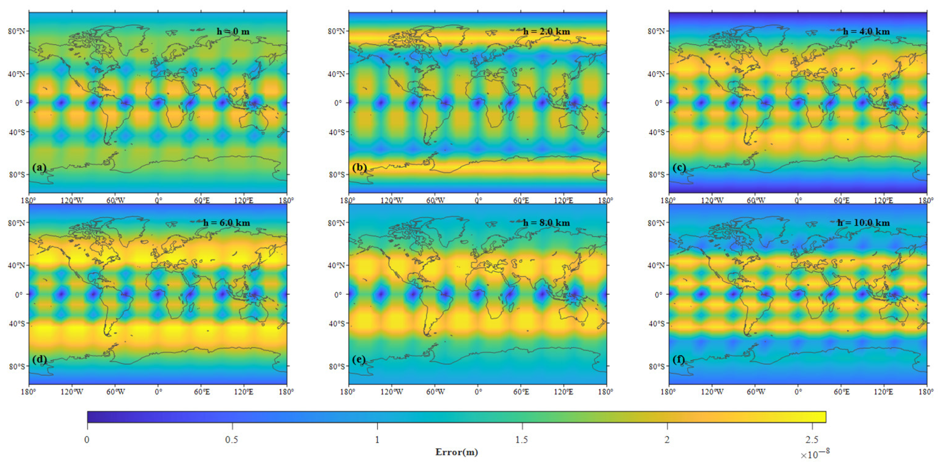
The experimental results are presented in
Figure 4, which shows the distributions of the 3D adaptation errors induced under various latitude, longitude, and altitude conditions.
The experimental results indicate that the UAPE method has extremely high accuracy in static mode, with its 3D positioning error remaining stable and uniformly distributed overall. The regularity of the error distributions is primarily reflected from the following two aspects:
Impact of latitude variations on errors: The lowest and most uniform errors were observed in low-latitude regions (e.g., near the equator). In contrast, the errors slightly increased in the midlatitude and high-latitude regions. This phenomenon is attributed mainly to the geometric characteristics of the Earth ellipsoid model. In high-latitude areas, the curvature effects of the Earth become more pronounced, leading to a slight increase in the errors induced during the coordinate transformation process. However, the overall accuracy remains low;
Impact of altitude variations on errors: The effect of altitude changes on the induced errors was negligible, with the error variations from near-ground altitudes (0 km) to high altitudes (10 km) not exceeding 10−8 m. This finding demonstrates that the adaptation method exhibits strong robustness across different flight altitudes.
The experimental results show that the proposed method demonstrated high precision in static mode, with positioning errors generally maintaining the order of 10−8 m and a maximum recorded error of 2.547 × 10⁻⁸ m. The 3D positioning errors were stable and uniformly distributed. The error distribution pattern reveals two key trends. First, the errors in low-latitude regions (e.g., near the equator) were the smallest and most evenly distributed, whereas slight error increases were observed in mid- and high-latitude regions. This is primarily due to the geometric properties of the Earth ellipsoid, as the curvature effect becomes more pronounced at higher latitudes, leading to a small increase in the errors induced during the coordinate transformation process; however, the overall precision remains low. Second, altitude changes had minimal effects on the errors, with variations not exceeding 10−8 m from near the ground (0 km) to high altitudes (10 km), indicating the robustness of the adaptation method across different flight heights under static conditions.
The grid-like distribution of errors in
Figure 4 primarily results from the discrete sampling intervals of latitude, longitude, and altitude (15°/15°/2 km), which introduce quantization effects. These, combined with the resolution sensitivity of coordinate rounding and ephemeris parameter modeling, lead to structured variations that reflect sampling granularity rather than algorithmic flaws. Despite this, the method maintains high accuracy under static conditions across global regions, confirming its robustness and applicability as a foundation for subsequent dynamic simulations.
3.2. Simulation of the Uniform Motion Mode
This experiment was intended to validate the performance of the proposed UAPE method under the assumption of uniform linear motion for airborne platforms, as discussed in the section on conducting parameter adaptation for the motion trajectories of airborne platforms. A systematic simulation was designed to evaluate the effectiveness of the proposed method in this scenario, focusing on the divergence of the navigation message adaptation errors across different latitudes and motion speeds and highlighting the error contributions derived from the omission of second-order and higher-order terms in Equations (11) and (12).
3.2.1. Experimental Design
To comprehensively evaluate the algorithm performance across various operational conditions, representative parameters were selected as shown in
Table 4.
To comprehensively evaluate the performance of the UAPE method under varying motion conditions, uniform speeds of 10 km/h, 100 km/h, and 300 km/h were selected. The first two values represent typical operational velocities of commercial UAVs and small fixed-wing platforms, as supported by the UAV performance data in [
27]. The 300 km/h case, although exceeding standard UAV speeds, is included to assess the scalability and upper-limit robustness of the UAPE method in high-dynamic scenarios, such as those involving advanced air-based platforms, future high-speed UAVs, or small aircraft equipped with GNSS enhancement modules.
The simulation duration was set to 15 min (900 s) with a sampling interval of 1 s, resulting in 900 simulation epochs. This duration was selected based on theoretical error propagation analysis and practical operational considerations. According to Equation (21), the maximum error growth rate is proportional to the square of elapsed time from the reference epoch. Our preliminary analysis indicated that error saturation behavior becomes evident within 15 min for the velocity range under consideration, making this duration sufficient to characterize both short-term accuracy and long-term error divergence patterns. Additionally, 15 min represents a typical autonomous operation segment for medium-range UAVs between waypoints or navigation reference updates, making this timeframe particularly relevant for practical applications. The 1-s sampling interval was chosen to match the standard output rate of commercial GNSS receivers, ensuring results that accurately reflect real-world operational conditions.
3.2.2. Result Analysis
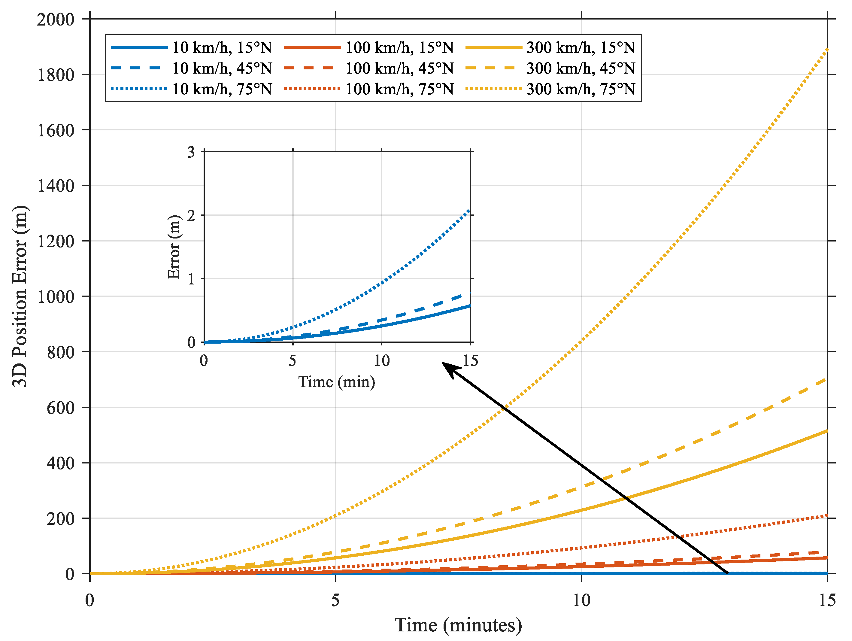
In each epoch, the actual position of the platform was compared with the predicted position, and the resulting 3D positioning error was calculated. Finally, the variations exhibited by the 3D positioning error over time were plotted, as shown in
Figure 5.
We conducted a statistical analysis of the adaptation errors induced by the airborne platform under varying departure latitudes and flight speeds. The results are summarized in
Table 5 below.
The statistical results in
Table 3 reveal a significant latitude-dependent divergence in the adaptation errors. At 15° N, the errors remained relatively low (0.566 m, 57.157 m, and 514.677 m at 10 km/h, 100 km/h, and 300 km/h, respectively). However, the errors increased sharply at higher latitudes, reaching 2.061 m, 208.072 m, and 1892.761 m under the same conditions at 75° N. This trend stems from the geometric properties of the Earth’s reference ellipsoid and the truncation effects of Taylor series models.
The second-order derivative of latitude
B with respect to
x is expressed as follows:
This demonstrates the nonlinear sensitivity of B to positional deviations. At high latitudes, decreases because of the proximity to the Earth’s rotational axis, amplifying the magnitude of . This increases the Hessian matrix term , which governs the second-order truncation error in the Taylor expansion formula. Consequently, neglecting higher-order terms leads to an accelerated error accumulation process.
Furthermore, the curvature radius in Equation (4) decreases at high latitudes, reducing the effective angular resolution and magnifying the impact of linearization approximations. These combined effects explain the observed error amplification in the polar regions. The results underscore the necessity of a latitude-aware parameter optimization strategy for mitigating the geometric nonlinearities that are inherent in the ECEF-to-geodetic coordinate transformation.
3.3. Impact of Different Update Frequencies on Positioning Errors
In practical applications, navigation messages cannot be updated at infinitely small intervals. However, low update frequencies lead to significant cumulative errors, reducing the attained positioning accuracy. The error divergence exhibited by the uniform motion model under different update frequencies is examined in this section to assess the necessity of increasing the update frequency under resource constraints.
3.3.1. Experimental Setup
The update frequencies were set to 5 min, 15 min, 30 min, and 60 min, representing different navigation message update intervals. The motion mode of the platform was configured as uniform linear motion with a constant speed of 100 km/h (approximately 27.78 m/s). The initial position of the platform was assumed to be located at an altitude of 5 km above the Earth’s reference ellipsoid.
During the experiment, the navigation message parameters were updated at specified intervals. In every update epoch, the parameters were recalibrated; between updates, the position of the platform was predicted via the received navigation message parameters and Equation (6). The positioning accuracy of the method was evaluated by calculating the 3D positioning error, which was defined as the difference between the actual position of the platform and the predicted position.
3.3.2. Result Analysis
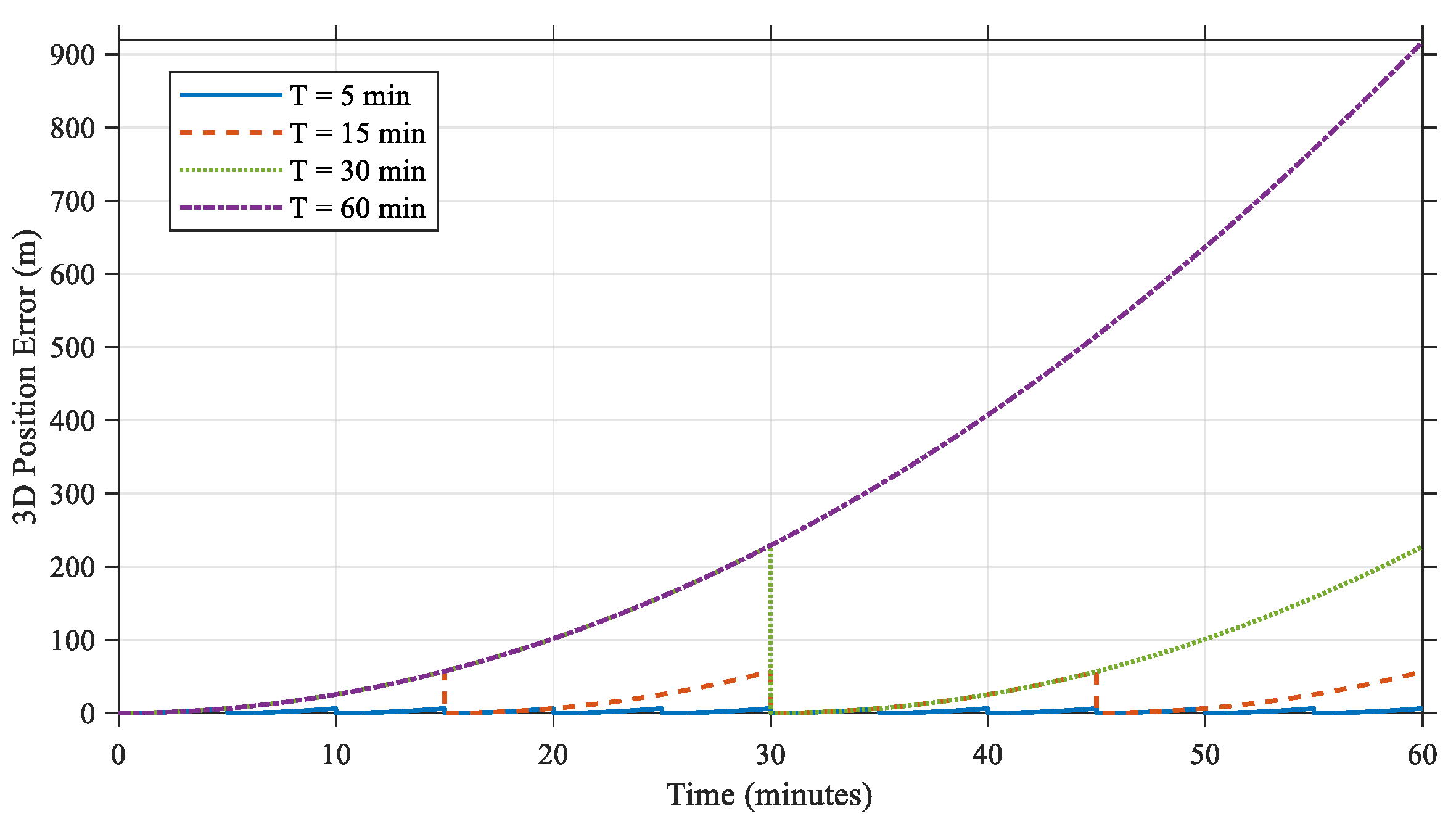
Time—error curves, which illustrate the 3D positioning errors induced over time under different update frequencies, were plotted to analyse the impact of the update frequency on the attained positioning accuracy. The results are shown in
Figure 6.
A comparison among the error curves under different update frequencies clearly reveals that shorter update intervals (300 s and 900 s) resulted in smaller errors with relatively minimal fluctuations over shorter durations. In contrast, longer update intervals (1800 s and 3600 s) led to continuously accumulating errors, with more pronounced growth over time.
This phenomenon highlights the trade-off between the update frequency and positioning accuracy. While low-frequency updates help reduce the computational load imposed on the system, they come at the cost of degraded positioning accuracy. This is particularly problematic during extended operations, where the cumulative error effect becomes increasingly significant.
To provide a systematic approach for determining appropriate update frequencies, we develop a mathematical model grounded in the truncation error analysis presented in
Section 2.4. When characterizing airborne platform motion using GNSS-compatible ephemeris parameters, the dominant source of positioning error arises from the truncation of higher-order terms in the Taylor series expansion. As shown in prior derivations, this truncation error is closely related to both the square of the platform velocity and the square of the time interval between message updates. For a first-order approximation, where second-order terms dominate the residual error, the maximum allowable positioning error
can be related to the Hessian norm
, platform velocity
, and update interval
as follows:
A more accurate expression for the Hessian norm, accounting for latitude-dependent geometric nonlinearity, is given by:
where
is a scaling constant dependent on the Earth’s ellipsoid parameters and the specific parameterization method. This form captures the increasing geometric distortion at higher latitudes through the
term and reflects the impact of Earth’s curvature on the second-order derivatives of the orbital parameters. Substituting Equation (24) into the error model and solving for the maximum permissible update interval, the required update frequency becomes:
This refined expression explicitly reveals that the required update frequency increases with latitude, particularly in high-latitude regions, which aligns with the error amplification trends observed in our simulations. For example, under typical UAV mission parameters in mid-latitude regions (approximately 45°) with a cruising speed of 100 km/h and a target positioning accuracy of 5 m, the model suggests that navigation messages should be updated approximately every 180 s. In contrast, under the same velocity and accuracy constraints but at higher latitudes (e.g., 75°), the update frequency must increase to approximately once every 100 s to maintain the same error bound. This demonstrates the practical utility of the proposed model; taking into account geographic location, velocity, and accuracy requirements, it enables precise determination of optimal update intervals that ensure positioning reliability while avoiding unnecessary communication overhead or system resource consumption.
3.4. Impact of Higher-Order Corrections on Positioning Errors
In the earlier analysis, the simulation results derived from the static mode experiment demonstrated that extremely high adaptation accuracy can be achieved with only first-order corrections or minimal perturbation adjustments. However, the uniform motion mode experiment showed that, particularly at higher speeds or over extended durations, neglecting higher-order motion characteristics in a first-order approximation results in gradually increasing positioning errors. Additionally, the impact of the update frequency experiment highlighted that reducing the update frequency of navigation messages amplifies cumulative model errors, especially in high-speed or long-duration scenarios.
To address these limitations, we evaluated the performance of different higher-order correction strategies on the basis of the higher-order Taylor expansion and parameter fitting methods described in the higher-order correction strategy section.
3.4.1. Experimental Design
The experiment was designed to systematically assess the positioning accuracy under different correction strategies across a progressive range of platform velocities. A fixed operational duration of 15 min (900 s) was used for all test cases to ensure consistent conditions for comparison. The tested horizontal flight speeds (100, 300, 500, and 700 km/h) cover both moderate and high-speed flight regimes, representative of platforms ranging from UAVs to small high-speed aircraft. The test trajectory followed a straight, constant-velocity path at a constant cruising altitude of 500 m, with 1-s sampling intervals matching standard GNSS receiver output rates. The experimental parameters are summarized in
Table 6.
Each correction strategy was applied across all defined speed scenarios to generate adapted navigation message parameters. These parameters were then used to reconstruct platform positions over the simulation duration using the proposed adaptation framework. The resulting trajectories were compared against the ideal uniform linear motion paths defined by the corresponding speed and direction parameters, which served as the reference for assessing modeling accuracy. All positioning errors were computed directly in the Earth-Centered Earth-Fixed (ECEF) coordinate frame, allowing for consistent and globally interpretable evaluation of spatial deviations. The results of this analysis are presented and discussed in
Section 3.4.2.
3.4.2. Result Analysis
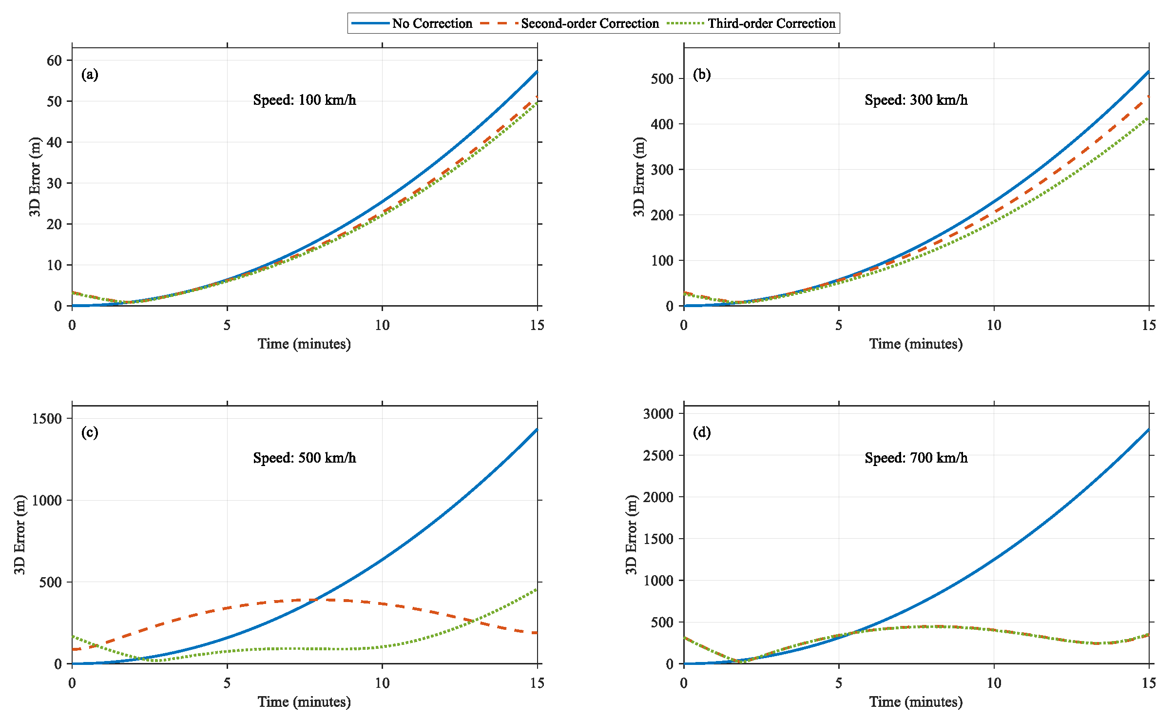
The experimental procedure mirrored that of the uniform motion mode experiment. After the initial position and velocity vectors were fixed, the true trajectory of the airborne platform was calculated from t = 0 s to t = 900 s and compared with the predicted trajectories obtained via various correction strategies. The 3D positioning errors induced by each method were computed in every epoch, and the resulting real-time error curves were plotted, as shown in
Figure 7.
The simulation results indicate that under low-to-moderate speeds (100 km/h and 300 km/h), both the second-order and third-order correction schemes significantly reduced the cumulative errors, with minimal differences between the two approaches. This suggests that within this speed range, the additional accuracy improvement provided by higher-order corrections is limited. However, as the platform speed increased to high-speed conditions (500 km/h), the effectiveness of the second-order corrections began to diminish, whereas the third-order corrections maintained relatively low error levels throughout most of the period, demonstrating better adaptability. Under ultrahigh-speed conditions (700 km/h), the rapid increase in linearization errors within the model caused significant cumulative errors, even with third-order corrections. While third-order corrections could partially mitigate the error divergence issue, the errors ultimately remained at relatively high levels. This finding indicates that although higher-order corrections provide improved dynamic error performance under high-speed conditions, linearization errors become the primary bottleneck affecting the navigation accuracy achieved in ultrahigh-speed scenarios, limiting further improvements that are achievable by the current correction methods.
To provide a more comprehensive performance evaluation, the high-speed range from 0 km/h to 1000 km/h was further examined. For each speed value, the platform followed a uniform linear motion mode for 15 min, using “No Correction,” “Second-Order Correction,” and “Third-Order Correction” to fit the ephemeris parameters. The primary metric of interest was the maximum 3D positioning error induced during the 15-min simulation process (i.e., the maximum fitting error), and its relationship with speed was plotted as a curve, as shown in
Figure 8.
The experimental results revealed that as the speed increased, the maximum positioning error under the “no correction” condition increased rapidly in a nonlinear fashion. This was particularly pronounced in the high-speed range (>700 km/h), where the cumulative errors exceeded 3000 m, reflecting the limitations of the linearization assumption employed by the model. The second-order corrections performed well in low-to-moderate speed ranges (<500 km/h), effectively suppressing errors. However, in the high-speed range (>700 km/h), the error suppression effect of these corrections became significantly limited. In contrast, the third-order corrections offered some improvement under high-speed conditions but remained insufficient for fully mitigating the significant cumulative errors induced by high-speed motion.
These findings suggest that in ultrahigh-speed scenarios, relying solely on existing higher-order corrections is inadequate for satisfying accuracy requirements. Further improvements may require the integration of higher-frequency navigation message updates or more sophisticated dynamic models to achieve increased positioning accuracy.
4. UAV Flight Experiment and Signal Reuse Experiment and Analysis
4.1. UAV Flight Experiment
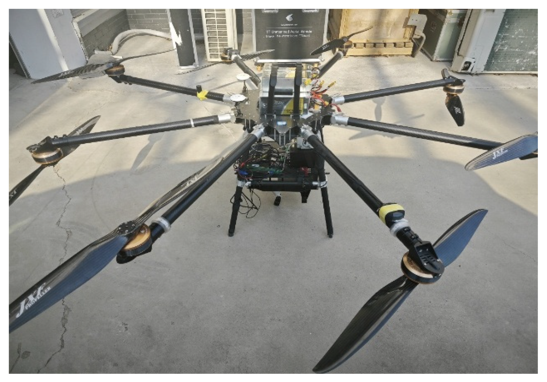
The aforementioned simulation experiments validated the theoretical effectiveness of the UAPE method. To further evaluate its performance in practical applications, this section describes flight experiments conducted with real UAV platforms. The experimental platform utilized the Tian-Tu Aviation M8FD octocopter, which is known for its exceptional stability and reliability, making it suitable for high-precision navigation testing. The platform was equipped with an Ellipse-D high-precision GNSS receiver from SBG Systems (Carrières-sur-Seine, France), integrating a dual-antenna Real-Time Kinematic (RTK)-aided Inertial Navigation System (INS) for precise positioning and orientation. This system integrates the multifrequency reception capabilities of a GNSS with a high-precision inertial measurement unit (IMU) and is capable of providing centimetre-level positioning accuracy. The ellipse-D system ensures a high-precision and complete data collection process by performing GNSS/INS data fusion in real time, providing a reliable measurement foundation for the subsequent data analysis and model validation steps. This use of RTK/INS fusion for real-world validation aligns with recent sensor-fusion practices recommended for UAV navigation systems [
28]. The airborne platform used in the experiment is shown in
Figure 9, below.
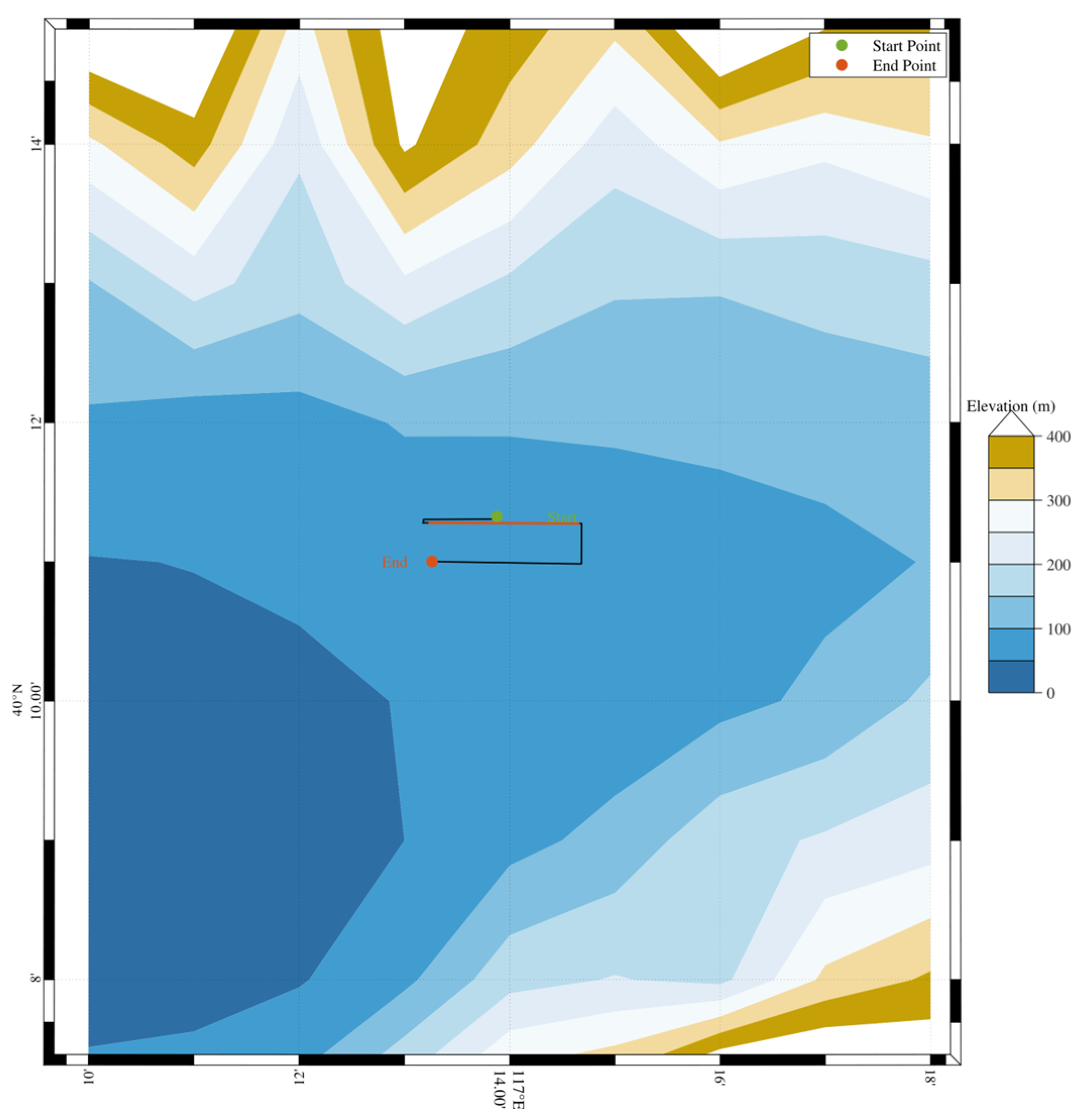
The experimental site was located in an open area near the geographic coordinates of 40° N, 117° E. This location was chosen because it is far from tall buildings and dense forests, minimizing the effects of multipath interference and signal occlusion on the experimental results. The average altitude of the site was 175 m, providing ideal environmental conditions for the experiment.
The experimental plan included two typical flight modes: static hovering tests and uniform linear flight tests. The static hovering tests were conducted at the initial moment of uniform linear motion, with the position used to evaluate the accuracy of the ephemeris fitting model. The uniform linear flight tests had an average flight speed of 8.0075 m/s, a flight duration of 1000 s, and an altitude of approximately 150 m.
To verify the effectiveness of the UAPE method in practical scenarios, motion data derived from an actual airborne platform were analysed.
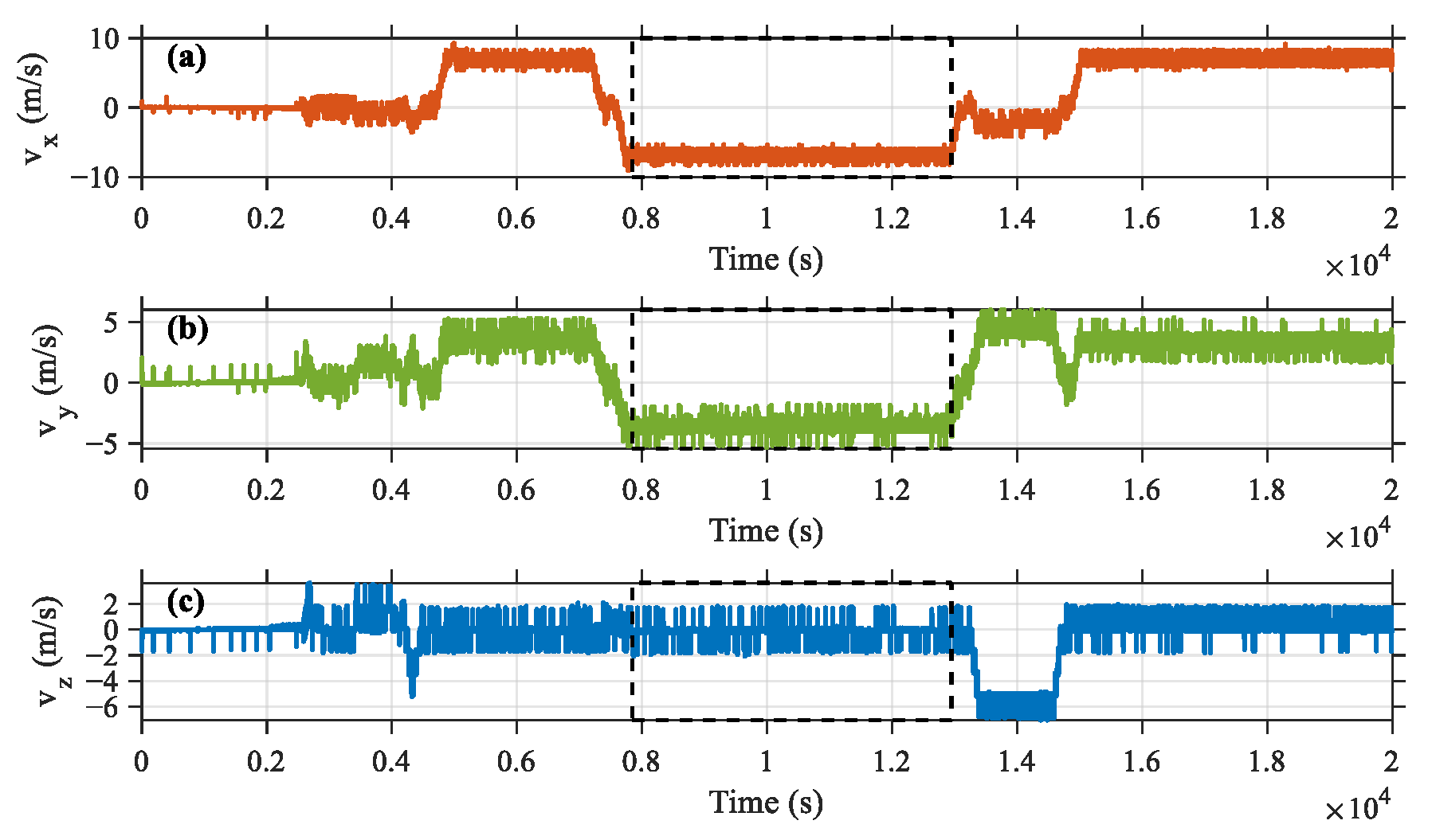
Figure 10 depicts the 2D trajectory of the airborne platform in the Earth-centred Earth-fixed (ECEF) coordinate system. The trajectory comprises multiple linear segments, and the platform maintains nearly uniform linear motion during specific operational intervals, which aligns with the assumption of simplified dynamic modelling in the UAPE algorithm. To further verify this observation,
Figure 11 presents the velocity variations exhibited by the platform in the X, Y, and Z directions.
On the basis of the analysis conducted on actual flight data, a specific time interval was selected for a detailed investigation. The red segment in
Figure 10 and the boxed portion of the velocity variation trends in
Figure 11 correspond to a period where the motion of the platform was relatively stable, conforming to the assumption of uniform linear motion. It was assumed that during this period, the platform transitioned into its navigation mode and began broadcasting GNSS-like navigation signals. On the basis of the proposed ephemeris fitting algorithm, the divergence between the actual fitting error of the platform and the theoretical fitting error was analysed to evaluate the performance of the UAPE algorithm during actual operations.
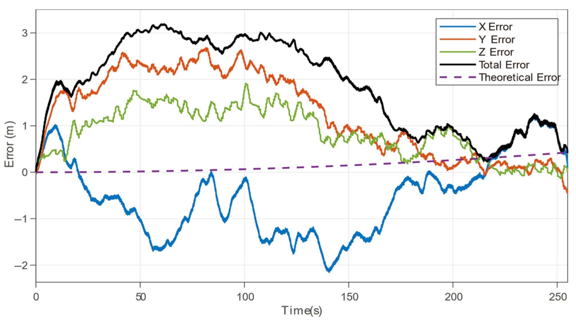
In
Figure 12, the reference trajectory is generated by assuming uniform linear motion from the platform’s position and velocity at the navigation message update epoch. The “theoretical error” represents the system-level adaptation error of the proposed method when encoding such a trajectory using standard GNSS ephemeris parameters. The plotted total error denotes the deviation between the actual UAV trajectory (from INS/RTK) and this predefined trajectory, capturing the combined impact of platform dynamics, control deviations, and environmental disturbances.
The experimental results, as shown in
Figure 12, indicate that during this specific period, a certain degree of divergence occurred between the actual fitting error and the theoretical fitting error of the platform. Under ideal conditions, assuming strictly uniform platform motion, the theoretical fitting error remained small, with a maximum value of 0.4262 m. However, in the actual environment, the influences of flight control system limitations and external disturbances cause the actual fitting error to gradually deviate from the theoretical value.
Figure 12 illustrates the error variations observed during this period, where the fluctuations exhibited by the actual error progressively increased. Although the maximum fitting error gradually increased over time, it remained within an acceptable range throughout the test period, with the peak 3D error reaching 3.1878 m. This indicates that the algorithm maintains stable performance even as the operational time increases.
Overall, the experimental results reflect some deviations between the actual fitting errors and the theoretical model, primarily due to influences from the flight control system and environmental factors. However, the positioning accuracy consistently remained within acceptable bounds, underscoring the adaptability and resilience of the ephemeris fitting algorithm. These results demonstrate that the UAPE method maintains reliable performance under dynamic and nonideal conditions, indicating strong potential for real-world applications.
It is worth noting that the average flight speed in the real-world experiments was approximately 8 m/s (29 km/h), significantly lower than the 300–700 km/h range explored in simulations. This discrepancy arises from practical constraints and safety considerations in UAV field testing. Nonetheless, the experimental results align well with low-speed simulation outcomes, supporting the validity of the proposed model in typical UAV scenarios. While the physical modeling framework and error propagation characteristics suggest extensibility to higher speeds, the extrapolation from low-speed validation to high-dynamic regimes should be treated with caution, as nonlinear effects and higher-order deviations become increasingly significant.
4.2. Navigation Message Reception and Parsing Experiment
To achieve accurate characterization of air-based platform trajectories using navigation messages, it is first necessary to ensure the correct reception and parsing of navigation message parameters. To this end, this experiment simulates the dynamic behaviour of air-based platforms under the real flight trajectory conditions described earlier and verifies the accuracy and adaptability of navigation messages in the reception, parsing, and trajectory characterization processes, providing important support for the subsequent evaluation of the effectiveness of the optimization method.
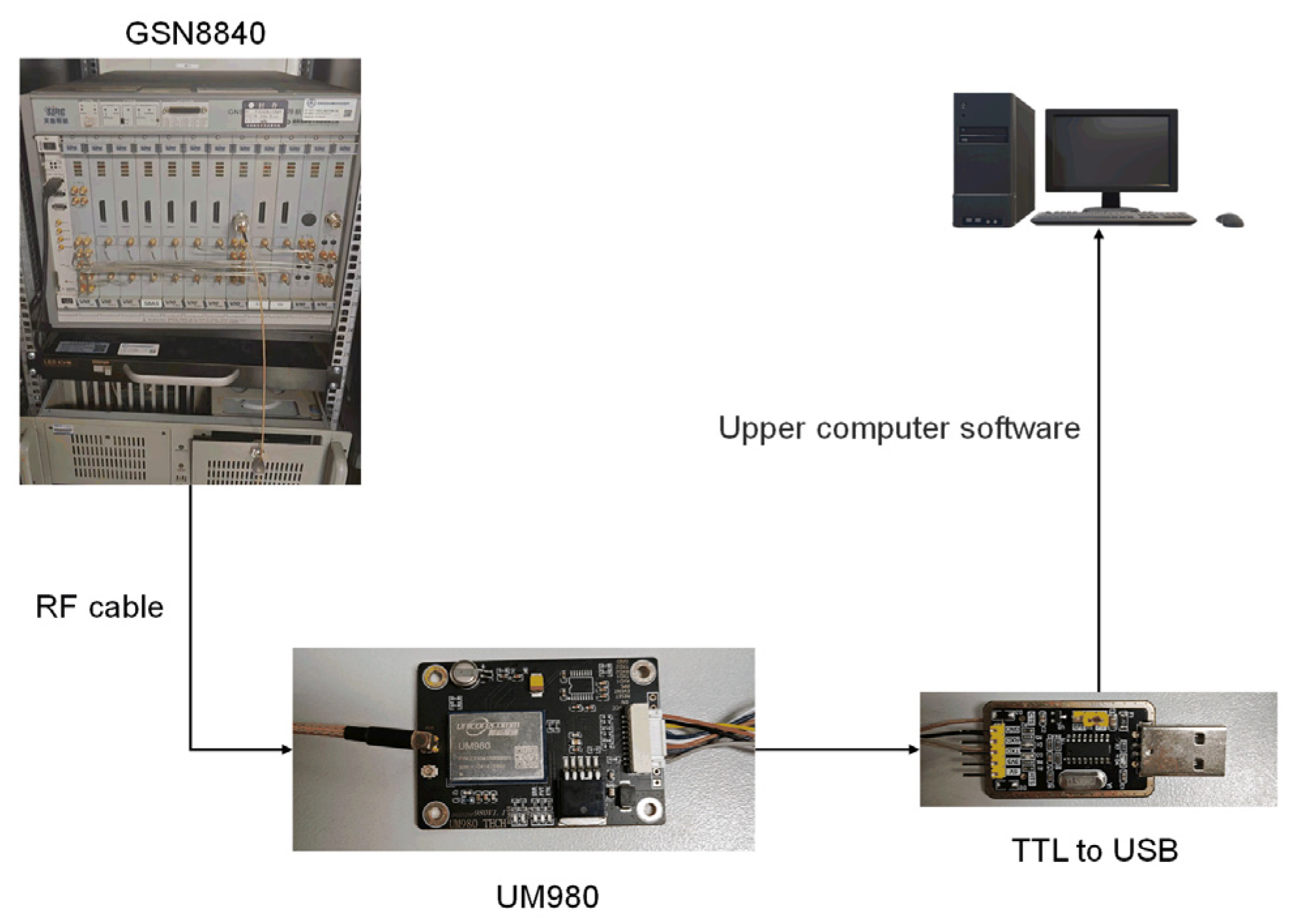
The experiment utilized the GSN8840 Beidou signal simulator manufactured by Hunan Matrix Technology (Changsha, China), which is capable of outputting navigation signals that are compliant with the Beidou B1C signal system. Specifically, the ephemeris parameters embedded in the B1C signals were calculated by following the steps outlined in the ephemeris adaptation method described in the previous section. The B1C signals output by the GSN8840 simulator were then transmitted to the Beidou UM980 receiver module via an RF cable.
The UM980 module is a widely used commercial GNSS receiver that is known for its high-precision signal reception and demodulation capabilities. It simulates traditional GNSS receiver signal processing operations, including signal acquisition, tracking, and demodulation, in real-world environments. By applying the ephemeris parameter adaptation algorithm, the existing receiver equipment was successfully reused, enabling accurate representation of the position of the airborne platform without requiring significant modifications to the hardware or software frameworks. The navigation information demodulated by the UM980 module was output via upper-level software for subsequent data analysis and processing steps, allowing for precise positioning of the airborne platform.
The experimental setup is illustrated in
Figure 13:
In this experiment, owing to the limitations of the GSN8840 signal simulator, the device supported setting the ephemeris parameters of the B1C signals broadcast by inputting RINEX 4.0 ephemeris files. Therefore, the ephemeris parameters were calculated via the proposed ephemeris parameter adaptation algorithm and used as inputs for the simulator settings. The modified ephemeris file was then used to broadcast the adapted B1C signals.
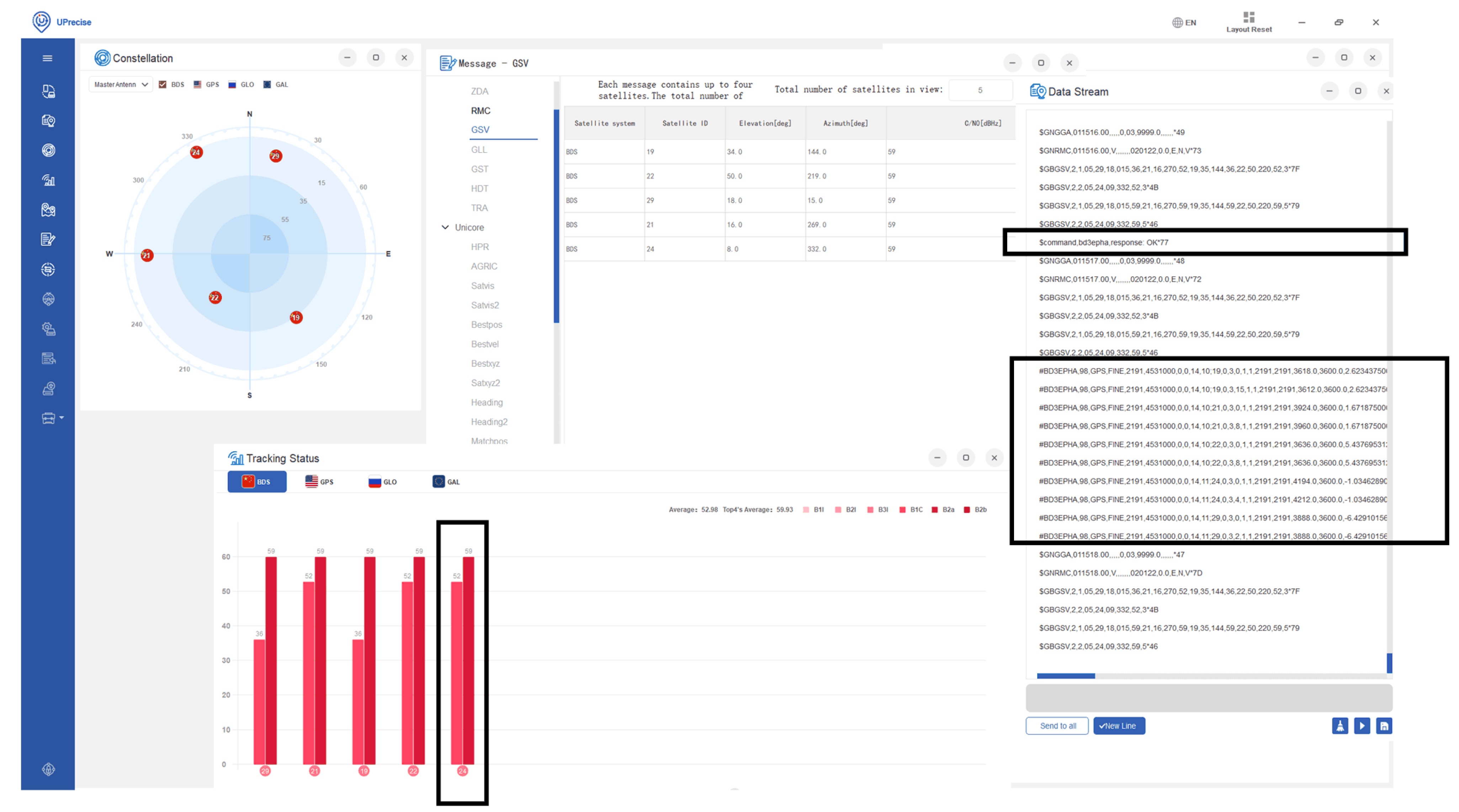
As shown in
Figure 14, the modified B1C signal broadcast by satellite 24 was successfully received and demodulated by the UM980 receiver module. The UM980 module effectively captures the signal and outputs the ephemeris parameters representing the position of the airborne platform through its demodulation process. This demonstrates the effectiveness of the proposed ephemeris parameter adaptation method, validating its ability to represent the position of the airborne platform without requiring significant hardware or software modifications.
The demodulated values of the parameters that primarily determine the ephemeris adaptation error were compared with the corresponding configured values, as shown in
Table 7. When the proposed ephemeris parameter adaptation algorithm was used, the actual navigation signals demodulated by the receiver were highly consistent with the configured target parameters. This finding indicates that the algorithm exhibits excellent accuracy and robustness when the motion trajectory of the airborne platform is reused by existing GNSS receivers.
Although minor errors were observed, these errors are negligible for the application scenarios considered in this study. Therefore, the use of existing GNSS equipment in combination with the proposed adaptation algorithm for the positioning and navigation of airborne platforms can satisfy high-precision requirements. Moreover, this study provides effective technical support for future applications of GNSSs in airborne platform scenarios.
5. Conclusions
This paper proposes UAV-based Adaptive Positioning via Ephemeris (UAPE), a method for encoding airborne platform motion into standard GNSS navigation messages. UAPE ensures compatibility with existing sensor-based positioning systems without requiring any receiver modifications, offering a practical solution for enhancing navigation performance in complex environments. Simulation and experimental results support the following conclusions:
(a) In stationary mode, UAPE introduces negligible positioning error; at low speeds, meter-level accuracy can be achieved without higher-order corrections.
(b) For moderate-speed or medium-duration flight scenarios, shortening the broadcast interval to 300 s and incorporating higher-order corrections can effectively limit positioning errors to the meter level, suppressing cumulative divergence.
(c) Both simulated and real-world data validate the feasibility of UAPE, confirming its potential for GNSS message parameter reuse in airborne navigation enhancement and providing a low-cost, high-precision solution adaptable to typical operational environments.
However, the UAPE method exhibits clear performance degradation under extreme dynamic conditions. Specifically, at ultra-high speeds (e.g., above 700 km/h), error magnitudes can exceed 3000 m despite higher-order corrections, as shown in
Figure 8 and
Figure 12. These results indicate that the current piecewise uniform motion model and Taylor-based correction strategies are insufficient to capture rapidly changing kinematic behavior at such velocities. Future work will explore non-linear trajectory modeling, adaptive segmentation techniques, and flexible broadcast strategies to improve the robustness and accuracy of UAPE in highly dynamic or maneuver-intensive flight conditions.


