Article

Rotor Failure Compensation in a Biplane Quadrotor Based on Virtual Deflection

1
Department of Electrical Engineering, Institute of Infrastructure Technology Research and Management (IITRAM), Ahmedabad 380026, India
2
Department of Cybernetics and Biomedical Engineering, Faculty of Electrical Engineering and Computer Science, VSB-Technical University of Ostrava, 17. listopadu 2172/15, 708 00 Ostrava-Poruba, Czech Republic
*
Author to whom correspondence should be addressed.
These authors contributed equally to this work.
Drones 2022, 6(7), 176; https://doi.org/10.3390/drones6070176
Submission received: 15 June 2022 / Revised: 9 July 2022 / Accepted: 11 July 2022 / Published: 17 July 2022

Abstract

:
A biplane quadrotor is a hybrid type of UAV that has wide applications such as payload pickup and delivery, surveillance, etc. This simulation study mainly focuses on handling the total rotor failure, and for that, we propose a control architecture that does not only handle rotor failure but is also able to navigate the biplane quadrotor to a safe place for landing. In this structure, after the detection of total rotor failure, the biplane quadrotor will imitate reallocating control signals and then perform the transition maneuver and switch to the fixed-wing mode; control signals are also reallocated. A synthetic jet actuator (SJA) is used as the redundancy that generates the desired virtual deflection to control the pitch angle, while other states are taken care of by the three rotors. The SJA has parametric nonlinearity, and to handle it, an inverse adaptive compensation scheme is applied and a closed-loop stability analysis is performed based on the Lyapunov method for the pitch subsystem. The effectiveness of the proposed control structure is validated using numerical simulation carried out in the MATLAB Simulink.

1. Introduction

Nowadays, Unmanned Aerial Vehicles (UAVs) play a key role in all sectors that affect human life directly and indirectly. UAVs are used in traffic monitoring [1], precision agriculture (PA) [2], humanitarian relief [3], bathymetric mapping [4,5], payload delivery [6]. Among these, payload delivery by a UAV has become common because it saves time as well as energy; in general, conventional quadrotor UAVs are used for payload delivery. A biplane quadrotor is more suitable for the payload delivery than a rotary-wing UAV because it is a hybrid-type UAV that can fly like both rotary-wing and fixed-wing UAVs. Many researchers have worked to developed a design and control methodology for hybrid quadrotor. Proof-of-concept of variable pitch biplane quadrotor for the payload delivery is developed and demonstrated by [7]. A morphing winglet is developed for the biplane quadrotor with enhanced efficiency in [8]. There are many linear and nonlinear control schemes that have been developed to control hybrid UAVs, such as PID [9], LQR [10], and SMC [11,12,13]. Dalwadi et al. [14] developed a backstepping controller for the trajectory tracking and nonlinear disturbance observer-based backstepping controllers to handle wind gusts in the quadrotor mode for a tail-sitter quadrotor, while a hybrid controller based on two different nonlinear control methods was designed for the trajectory tracking of biplane quadrotors [15].
UAVs are highly nonlinear and coupled systems that become more complex and unstable during rotor failure. There have been many control structures developed to handle rotor failure during flight. Investigation and controlling strategies for the one or more rotor failures in a hexacopter while in the hover state is presented in [16] and NTSMC (Non-singular Terminal Sliding Mode Control) for total rotor failure in quadrotor is presented [17]. AFTCS is developed and implemented in hardware by Saied et al. [18] for an octocopter UAV. However, a deep neural network-based fault detection algorithm is developed for the octocopter [19]. The crash probability density (CPD) is evaluated based on the Newton’s laws, as well as Galileo’s free fall for different types of UAVs using MATLAB simulation carried out in MATLAB in [20].To handle rotor failure in the quad-plane, a novel I-ASMC is proposed in [21]. For partial as well as total rotor failure in quadrotor UAVs, a robust, linear parameter-varying observer is designed, and its effectiveness is validated using numerical experiments in [22]. The fault recoverable measure for a nonlinear system like a UAV is presented [23], which is customized to ensure an adequate redundancy level for the achievement of FTC, and a guide to increase the redundancy level while the FTC is developed [24] to reconfigure the trust system based on the optimal control during the failure in the multi-rotor UAVs. A complete active FTC system for quadrotor UAVs has been developed [25], while the BSMC approach and iterative learning algorithm-based FTC are developed in [26]. A meta-learning-based scheme is developed to improve the trajectory tracking performance of UAVs in the presence of the failure in the system and external disturbance [27], and a model-free deep reinforcement learning scheme is applied for a quadrotor with signal rotor failure in [28]. A hierarchical FTC is designed for a hexacopter, where an adaptive sliding mode controller is used for normal operation, and a sliding-mode-based controller is used for rotor failure [29]. To handle the partial rotor failure and wind gust acting on the biplane quadrotor with a slung load, a nonlinear disturbance-based backstepping control approach is developed in [30].
Researchers have shown more interest in small active flow devices in the last few decades because they substantially affect the flow field and can modify forces and momentum across the lifting surface. The main benefit of a synthetic jet is its zero net mass flux that removes the need for plumbing and, when applied to a base flow, causes unique effects not possible with steady or pulsed suction or blowing. Synthetic jets contain vortex pairs that provide more fluid than continuous jet columns [31]. The advantages of SJAs are their low cost, simple structure, easy operation, compactness, and lower energy consumption. Primarily, our usage of SJAs as the specific choice among the various available active devices is because of the availability of mathematical SJA models at low angles of attack, which are needed for closed-loop control validation, as well as the successful experimental implementation of SJAs with this model in other flight regimes. The present application is a low angle of attack flight, so SJAs with a known model are attractive. It is not our contention that other active flow control devices would not work in such an application. We attempt to provide an on-demand lift force (when rotor failure takes place) that is enough to land the vehicle safely. SJAs can change the flow separation pattern and potentially replace orthodox control surfaces such as flaps. An SJA produces a fluid flow of zero mass over an entire cycle. Still, the momentum is non-zero beyond a nozzle on the other side of the piezo-electrically driven diagram, which imposes an oscillating pressure gradient [32].
Many simulations and experiments have been conducted to study the SJA’s effect on the lifting surface. Tang et al. [33] proposed and validated a jet creation criterion for SJAs, while Zong et al. [34] presented a novel analytical mode of the PSJA (Plasma Syn- thetic Jet Actuator) in which the inertia of the throat gas and hear transfer effect are both considered. Based on this model, whole cycle characteristics can be predicted. A novel multi-meter-scale hybrid SJA is proposed to enhance the performance of a conventional SJA in active flow control for a supersonic aircraft [35]. MacKunis et al. [36] proposed a robust nonlinear tracking control method for an aircraft equipped with an SJA. Duvigneau et al. [37] presented a numeric simulation of the control of the aerodynamic stall angle using a synthetic jet actuator with automatic optimization of the control parameters and flow physiognomies; the impact of the particular control parameters were examined. An adaptive inverse compensation scheme is developed in [38] for controlling the SJA’s aerodynamic flow on a dynamic aircraft system.
A novel technique for controlling next-generation air-crafts by using SJA is proposed in [39] where aircraft dynamics controlled by a state feedback controller and adaptive laws ensure closed-loop stability and asymptotic tracking. In contrast, a neural network-based adaptive compensation structure eliminates the effect of ambiguous, highly complex, and dynamic SJA nonlinearities [40]. Transcossi et al. [41] presented a numeric as well as the theoretical concept of the Coanda effect that can be used for aeronautical naval propulsion and industrial applications. The impact of the geometric parameters like height, diameters of the cavity as well as the orifice, shape, and edge configuration of the orifice on the performance of the SJA is discussed in [42]. SJA-based numerical simulation is carried out to improve the aerodynamics efficiency of the flying wing aircraft [43]. Jabbal et al. [44] developed an SJA array hardware to enhance high lift system efficiency in a wind tunnel model which consists of the design, manufacture, and bench test of the SJA array. Li et al. [45] proposed a novel AFC (Active Flow Control) method for an aircraft that does not have any deflecting surface but SJAs are used to get control over roll-pitch-yaw angle when a stall occurs.
Post et al. [46] have documented the control of leading-edge flow separation using plasma actuators while aircraft travels above stall angle. Numerical investigation of subsonic flow separation around an airfoil (NACA0012) with lower AoA ( 6 ° ) is investigated in [47] under (i) uncontrolled baseline case, (ii) controlled case with passive vortex maker, and (ii) controlled case with active vortex maker. Lee et al. [48] performed 2-D laminar and 3-D implicit large eddy simulations to predict the separation point and features of a separation bubble of NACA 0012 airfoil accurately at Reynolds numbers 1 × 10 4 , 3 × 10 4 , and 5 × 10 4 and different AoA Table 1 using Reynolds-averaged Navier–Stokes with Baldwin-Lomax turbulence model 2-D RANS(BL).
NACA 0012 Airfoil 3-D suction flow control investigation is performed in [49] to understand the aerodynamic features of a rectangular wing. A DNS (Direct Numeric Simulation) is carried out to study the flow over NACA 0012 airfoil at 5 ° 15 ° AoA and adequate Reynolds numbers of R e = 50 × 10 3 and 1 × 10 6 [50]. In contrast, a numerical study is carried out to learn the flow over NACA 0012 airfoil to understand infrequent lift characteristics at low Reynolds numbers [51]. Castelli et al. [52] performed a 2D numerical simulation to investigate the ability of the γ θ transition model to forecast the laminar to turbulent transition and subsequent friction drag over a NACA 0012 airfoil for a Reynolds number of 3.6k. Mejia et al. [53] presented a computational study for the NACA 4415 with SJA for low AoA where SJA was placed close to the trailing edge and provided thorough information about the adjustment of airfoil aerodynamic properties. Wei et al. [54] applied an actuator to control the roll angle at high AoA of NACA 0015 airfoil with 0.3 m chord and 3 m span aerofoil, and 19 plasma actuators placed at the upper surface. At the same time, for the same aerofoil and control objective, [55], SJAs are placed at 12% of the chord with 45 ° angle and 150 Hz operation frequency. Active flow separation control using SJA installed near the location of the maximum thickness of the airfoil is proposed and implemented for the stall control of the NACA 0012 airfoil in a wind tunnel test [56], and the outcome shows 11 % improvement in lift coefficient and 4 ° stall angle increase. Li et al. proposed a novel AFC technology using an SJA for roll motion of morphing aircraft at high AoA [57]. Tang et al. [58] studied the effectiveness of the SJA arrays that are placed at 23 % and 43 % of the chord from the leading edge of a low-speed wing mode (used in small UAVs) and observed the delay and generate the high-momentum flow near the outer region.
Montazer et al. [59] discussed the optimization of the SJA in the control flow around the NACA 0015 at a 15 ° stall angle and 16 ° (post-stall angle) to maximize the performance of the airfoil. Jee et al. [60] investigated flow control using the SJAs on pitching and plunging airfoil LQR, and a neural network-based adaptive controller is joined to the CFD model, including the model of SJAs. Luca et al. [61] proposed a lumped element mathematical model of the SJA. Based on it, analytical and numerical investigations have been done to get more information about the frequency response of the SJA. SJA can be used for both fluid types: (i) water and (ii) air. In [62] underwater thrust vectoring method based on the double SJA is studied and validated using the numerical method. Caruana et al. [63] described the physics of the plasma SJA with numerical and experimental studies based on the description of the PSJA device with and without flow and the ability of PSJA actuators to reduce the separated flow region on a decelerating ramp as well as on a NACA 0015 airfoil. A neural network-based adaptive inverse compensation scheme is developed in [64] to cancellation of the effect of uncertainties in the SJA. An SMC (sliding mode control) scheme is used to achieve asymptotic SJA-based LCO suppression and suppression of both pitching and plunging movements for a class of so-called dual parallel underactuated systems in which a single scalar control signal concurrently disturbs both states [65].
In this paper, we propose a control structure for the biplane quadrotor to deal with total rotor failure where SJA is used as the redundancy, and suggest the SJA location should be after the separation point and close to the trailing edge ( 2 % to 15 % of chord length). We assume that rotor failure can happen at any time and in any mode of the biplane quadrotor during the flight, and such a mechanical arrangement is developed to reduce the unsteady flow around the wing generated by the rotors. To compensate for non-linearities in the SJA, an adaptive inverse compensation scheme is applied and an adaptive backstepping-based controller is designed for the pitching moments during fixed-wing mode, and that is provided by SJA. Lyapunov-based closed-loop stability analysis is proven. Simulation is carried out using MATLAB and the results show the effectiveness of the proposed control structure.

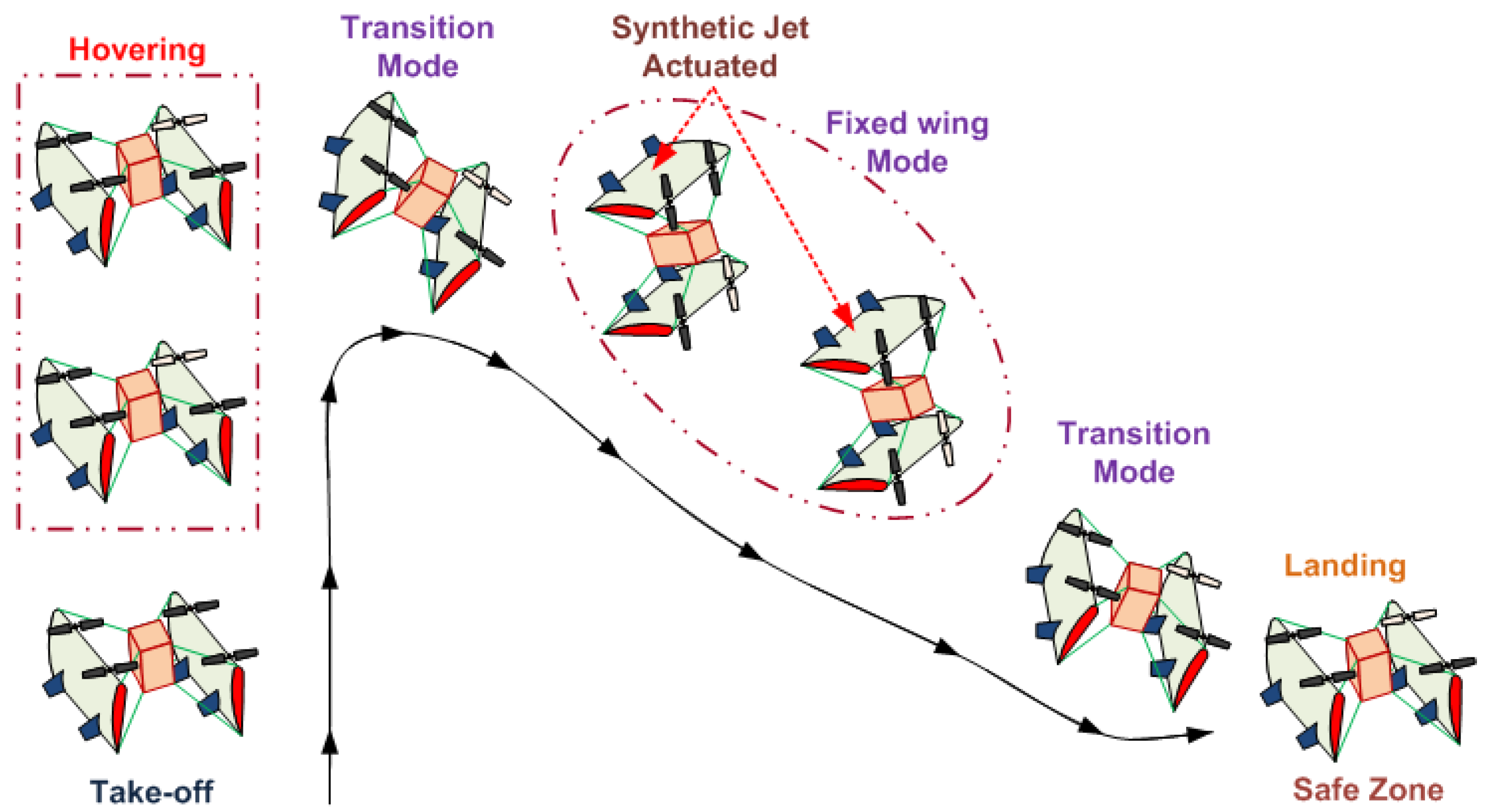
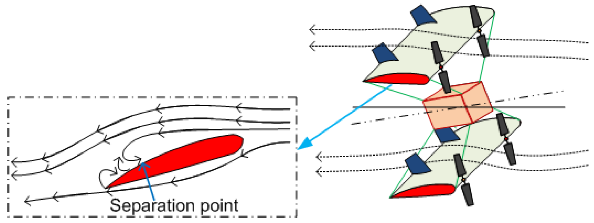
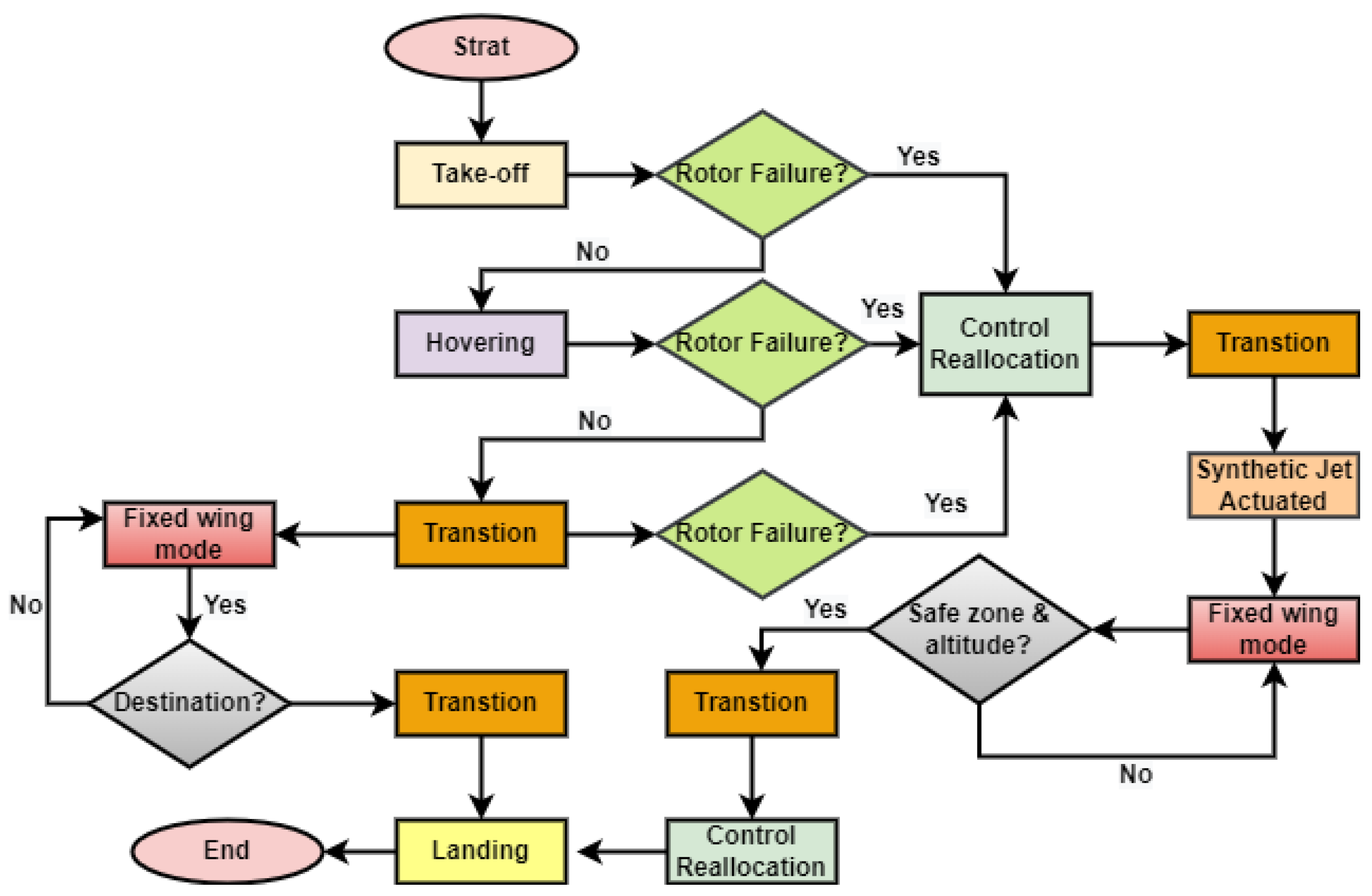
2. Biplane Dynamics and Rotor Failure

During the take-off, landing, and hovering state, the biplane quadrotor’s behavior is same as that of a conventional quadrotor, where no sufficient aerodynamics forces are generated, and during fixed-wing mode, it acts like fixed-wing UAVs. An animated picture of a biplane quadrotor UAV with all three modes is shown in Figure 1.
Biplane quadrotor dynamics are presented in [66] as
x ¨ = F a x m g s θ + r v q w
y ¨ = F a y m g s ϕ c θ + p w r u
z ¨ = F a z T m g c ϕ c θ + q u p v
ϕ ¨ = ( b 1 r + b 2 p ) q + b 3 ( L a + L t ) + b 4 ( N a + N t )
θ ¨ = b 5 p r b 6 ( p 2 r 2 ) + b 7 ( M a + M t )
ψ ¨ = ( b 8 p b 2 r ) q + b 4 ( L a + L t ) + b 9 ( N a + N t )
where c ( · ) = cos ( · ) and s ( · ) = sin ( · ) , linear acceleration is [ x ¨ y ¨ z ¨ ] , and velocity is [ u v w ] , while [ ϕ ¨ θ ¨ ψ ¨ ] is angular acceleration and angular velocity [ p q r ] . m is the mass and T is the thrust. The moments are [ L t M t N t ] , the aerodynamic forces are [ F a x F a y F a z ] are aerodynamic forces, and aerodynamic moments [ L a M a N a ] act on the biplane quadrotor. Inertial terms are defined as constant b i :
b 1 b 2 b 3 b 4 b 8 b 9 = 1 I x I z I x z 2 ( I y I z ) I z I x z 2 ( I x I y + I z ) I x z I z I x z ( I x I y ) I x + I x z 2 I x , b 5 b 6 b 7 = 1 I y ( I z I x ) I x z 1 .
Rotor failure can happen at any time during the flight. Figure 2 shows the flow diagram of the proposed scheme. When failure is detected in quadrotor mode (take-off or hovering state), it will immediately reallocate the control signals to a point with no control over the yaw angle, and then perform the transition and switched to fixed-wing mode. The synthetic jets are actuated, and gradually reduce the altitude while navigating to the safe zone. The same procedure follows when the failure occurs in the transition mode and in fixed-wing mode when rotor failure happen, in which case, only the synthetic jet is actuated. The main advantage of this control structure is that there no need to compromise control over any of its states.
Animated picture of flow separation during fixed-wing mode and low AoA is shown in Figure 3, where it can be observed that flow separation starts from the trailing edge at low AoA.
The control allocation block provides suitable control signals to the actuator based on the control signals generated by the controller. There are two types of propulsion system used in the biplane quadrotor, (i) variable pitch, and (ii) a conventional BLDC motor-based propulsion system. In this paper, we used a conventional BLDC-motor-based propulsion system where thrust and moments are achieved using the RPM changes in the respective actuators. Control allocation for the biplane quadrotor without rotor failure is
T L t M t N t = k n k n k n k n k n l n k n l n k n l n k n l n k n l n k n l n k n l n k n l n d n d n d n d n Ω 1 2 Ω 2 2 Ω 3 2 Ω 4 2 ,
where [ T L t M t N t ] are the thrust and moments generated by the four rotors, k n , d n are the motor parameters, and l n is the distance between CoM and the respective motor of biplane quadrotor, and Ω i is the RPM of the i t h motor. Based on Equation (8), the RPM of the each rotor can be calculated as
Ω 1 2 Ω 2 2 Ω 3 2 Ω 4 2 = k n k n k n k n k n l n k n l n k n l n k n l n k n l n k n l n k n l n k n l n d n d n d n d n 1 T L t M t N t .
The proposed control structure is designed only for single-rotor failure. So, let us assume that among four rotors, rotor 1 fails. So, Equation (8) will become
T L t M t N t = k n k n k n k n l n k n l n k n l n k n l n k n l n k n l n d n d n d n Ω 2 2 Ω 3 2 Ω 4 2 ,
and the RPM calculation is
Ω 2 2 Ω 3 2 Ω 4 2 = k n k n k n k n l n k n l n k n l n k n l n k n l n k n l n d n d n d n 1 T L t M t N t ,
It is not possible to solve Equation (11), so one state has to compromise, and the equation becomes
T L t M t = k n k n k n k n l n k n l n k n l n k n l n k n l n k n l n Ω 2 2 Ω 3 2 Ω 4 2 .
Control allocation for the quadrotor mode and transition mode is given in Equation (12), where no control over the yaw angle is compromised.

3. Mathematical Mode of the SJA

A biplane is able to switch its mode after performing the transition maneuver. A biplane quadrotor is mostly used for payload delivery and, during its whole mission, the biplane quadrotor always flies with low AoA. We proposed a SJA-based redundancy for a biplane quadrotor when signal total rotor failure occurs. SJAs are connected at the trailing edge of the wings, because the biplane quadrotor is designed to fly with low AoA, and flow separation starts from the trailing edge while AoA is low. So, SJA should preferably be placed at the trailing edge of wings to reattach the separated flow. Total rotor failure can occur at any time of instance. To handle this rotor failure, the biplane will follow some maneuvers based on those at which mode fault occurred. When failure occurs during the quadrotor mode, the first step is to reallocate its control signals in such a way that there is no control over the yaw angle. Afterwards, the biplane quadrotor will perform a transition maneuver to switch the quadrotor mode to fixed-wing mode, and then SJAs are activated to control pitch moments while rolling and yawing moments are controlled by the remaining three rotors. When failure occurs in the transition mode, it will switch to fixed-wing mode, and then SJAs are activated. When total rotor failure occurs in fixed-wing mode, the SJAs are activated with no need to perform the transition.
Next, we will discuss the mathematical model of the SJA for the low AoA. As explained earlier, the biplane quadrotor is designed to travel at a low angle of attack during fixed-wing mode. Researchers have already developed a parametric model of the SJA [38,39] for the low AoA, and it is more suitable for the biplane quadrotor because it flies with low AoA. It is derived based on wind-tunnel testing, in which pick-to-pick voltage, air-stream flow, frequency, and chord length are considered. Parameter values may be changed for biplane quadrotor, but the structure of the model remains the same. So, this simulation study is carried out within the SJA low angle of attack model that is given in [67]. Now, let us consider the input voltage as v ( t ) and the equivalent virtual deflection as U a ( t ) = C l ( t ) , expressed by a non-linearity in SJA as N ( · ) :
λ s ( t ) = C l S ( t ) = N ( v S ( t ) ) = N ( A v 2 ( t ) ) ,
where v S J A ( t ) = A v 2 ( t ) , A v is input peak-to-peak voltage. For more simplifications, some assumptions are needed:
  • The actuator non-linearity’s N ( · ) output is not measurable.
  • Parameters of the actuator non-linearity N ( · ) are unknown.
  • Jet momentum does not vary during the entire period of the diaphragm motion.
  • The air-stream density and control of flow along the width are constant.
The SJ is actuated such a way that the control signal generates favorable changes in the virtual shape of the aerofoil. For unknown parameters p s i ,   i   =   1 ,   ,   4 with certain physical meaning, the SJA model at low AoA is given as
C l s ( t ) = p s 1 p s 2 p s 3 V f c C μ s ,
where f is the frequency in input voltage, c is the wing chord, and V is the free-stream velocity around SJA. C μ s is the momentum coefficient of the actuator, and it is given as
C μ s ( t ) = p s 4 A v 2 ( t ) V .

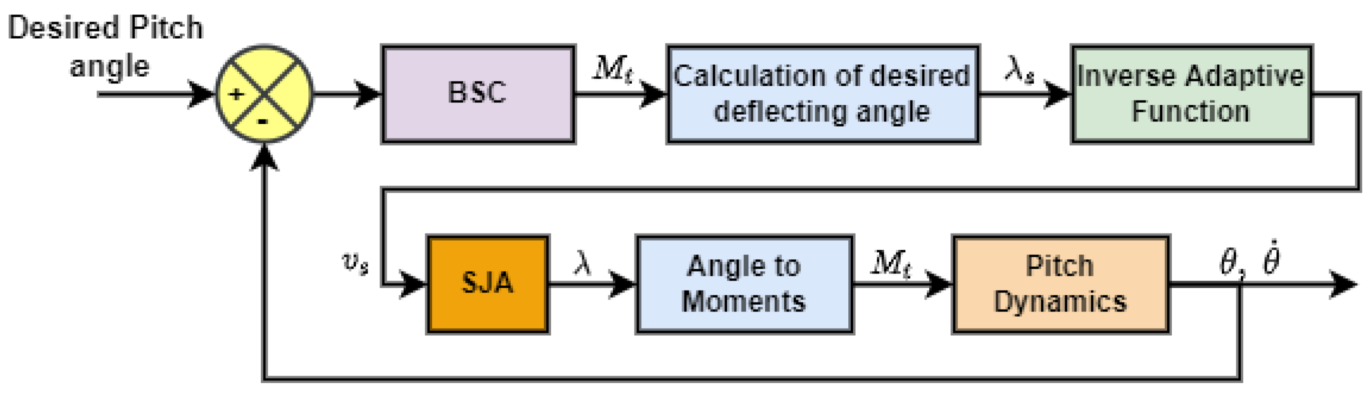
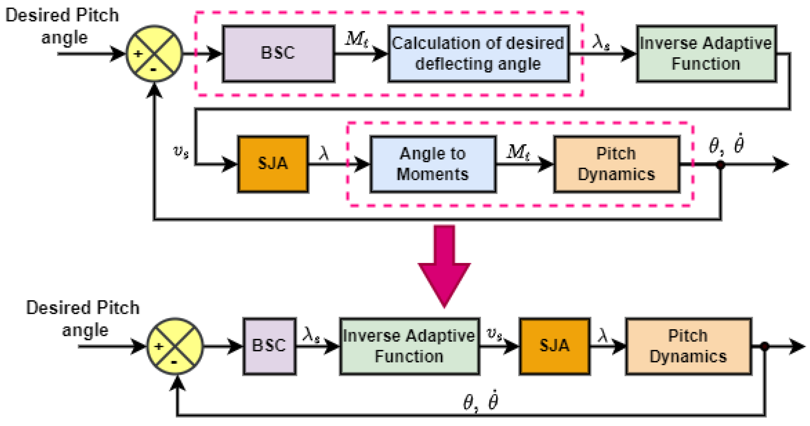
4. Control Architecture

To handle the total rotor failure in an underactuated system is a complex task. While reconfiguring the control allocation during the rotor failure, control over one parameter must be compromised, and generally, this parameter in the rotary wing UAVs is the yaw angle. It can be observed that the biplane quadrotor dynamics roll and the yaw angle are coupled. Here, we considere that the rotor fails during the hovering state. So, after the detecting the failure, the biplane quadrotor is commanded to perform the transition maneuver and switch to fixed-wing mode, and then it will fly with low velocity and navigate to a safe place to land. The control architecture flow diagram is shown in Figure 4.
Rotor failure can happen in any mode of a biplane quadrotor. So, if rotor failure happens in the quadrotor mode or transition mode, the biplane will first reallocate control signals in which there is no control over the yaw angle, and then immediately perform the transition and switch to fixed-wing mode. During fixed-wing mode, a synthetic jet is actuated and virtual deflection is generated to control the pitching moments of the biplane quadrotor. The biplane quadrotor’s altitude gradually declines, and it navigates to a safe zone and altitude. When the biplane quadrotor reaches the safe zone and altitude, it is commanded to switch into quadrotor mode and then reallocate the control signals, after which it will land without damage. The block diagram of the proposed control architecture to handle the biplane quadrotor in fixed-wing mode is shown in Figure 5.
The biplane quadrotor wing is enhanced with SJA as a redundancy. In fixed-wing mode, the altitude, roll, and yaw angles are controlled by the three rotors, and the pitch angle is controlled using the virtual deflection generated by the SJA. The control signal generated using the BSC controller is converted to the desired virtual deflection and then given to the inverse adaptive function block, and it will generate the desired voltage, which is given to the SJA mode block. Then, virtual deflection is generated. Again, it will convert based on the moment and the biplane dynamics. In fixed-wing mode, there are two types of forces acting on the biplane quadrotor. (i) Force generated by three rotors, and (ii) aerodynamic force and moments generated by the deflecting surface. The force and moments generated by the deflecting surface are
F = A ρ V 2 sin δ 2 , M = 2 F L
where F is the force generated and M is the moment generated by the surface. L is the distance from center of gravity, A is the area of the wing, ρ is the air density, δ is the angle of the deflecting surface, and V is the vehicle velocity. We use the simplified version of the force and moments equation because the objective is to demonstrate the effectiveness of the SJA on the biplane quadrotor from a control perspective.

5. Controller Design

Next, we design an inverse adaptive function of the SJA to compensate for parametric uncertainty. As shown in Figure 6, we combine the blocks of BSC with calculation of the desired deflecting angle and the angle of moments and pitch dynamics.
In our previous work [6], backstepping controller-based control laws are designed for the biplane quadrotor in quadrotor mode as
L t = 1 b 3 e ϕ k p e p + ϕ ¨ d k ϕ e ˙ ϕ b 1 r q b 2 p q b 4 N t ,
M t = 1 b 7 θ ¨ d e θ k q e q k θ e ˙ θ + b 6 p 2 r 2 b 5 p r ,
N t = 1 b 9 ψ ¨ d e ψ k r e r k ψ e ˙ ψ b 8 p b 2 r q b 4 L t ,
T = m c ϕ c θ e z + e w k w z ¨ d + k z e ˙ z + g ,
u x = m T e x + k u e u x ¨ d + k x e ˙ x ,
u y = m T e y + k v e v y ¨ d + k y e ˙ y .
Using (21)–(22), the desired roll and pitch angle are
ϕ d = arcsin u x u y s ψ + c ψ , θ d = arcsin u x u y s ϕ ( s ψ c ψ ) 2 c ϕ c ψ .
In transition mode, we get
L t = b 9 b 3 b 9 b 4 ( e ϕ k p e p k ϕ e ˙ ϕ + ϕ ¨ d b 1 r q b 2 p q b 4 b 9 e ψ k r e r k ψ e ˙ ψ + ψ ¨ d b 8 p q + b 2 q r ) L a ,
M t = 1 b 7 θ ¨ d e θ k q e q k θ e ˙ θ + b 6 p 2 r 2 M a b 5 b 7 p r ,
N t = 1 b 9 ( e ψ k r e r + ψ ¨ d k ψ e ˙ ψ ( b 8 p b 2 r ) q b 4 ( L t + L a ) b 9 N a ) ,
T = m c ϕ c θ e z + e w k w z ¨ d + k z e ˙ z + g F a z m .
For the adaptive compensation, parameter Θ * = [ Θ a * ( t ) , Θ b * ( t ) ] T is considered for the non-linear function N ( · ) and can be expressed as
λ = Θ b * Θ a * v s = N ( Θ * ; v s ) ,
where λ = [ 0 ° 20 ° ] and output voltage v s is non-negative. Let us take parameter estimation vector Θ ^ ( T ) = [ Θ ^ a ( t ) Θ ^ b ( t ) ] T and approximate adaptive inverse function given as
v s ( t ) = N ^ I ( λ s ( t ) ) = Θ ^ a ( t ) Θ ^ b ( t ) λ s ( t ) .
The error between actuator output λ and desired output λ s is computed. We assume λ s > Θ ^ b to avoid singularity. Using (27) and (28), after rearranging the error term, we get
λ λ s = Θ ^ b ( t ) λ s ( t ) Θ ^ a ( t ) ( Θ ^ a ( t ) Θ a * ) ( Θ ^ b ( t ) Θ b * ) .
The pitch angle dynamics of the biplane quadrotor in fixed-wing mode are
θ ˙ = q , q ˙ = b w 8 r 2 + b w 9 p 2 + 2 b w 10 p r + b w 7 ( λ s + M a ) ,
The error between the desired and actual pitch angle e θ = θ θ d and the Lyapunov function is desired V θ = 1 2 e θ 2 , and its time derivative is
V ˙ θ = e θ e ˙ θ = e θ ( q θ ˙ d ) ,
By using the virtual law q ˙ = θ ˙ d + K θ e θ .
V ˙ θ = e θ e q K θ e θ 2 .
Now, error in the pitch angle rates is defined as
e q = q d q ,
and the positively defined function and its derivative with virtual control law and parameter error is given as
V ˙ = V ˙ θ + V ˙ q + Θ ˜ a 2 2 γ a + Θ ˜ b 2 2 γ b , = e θ e q K θ e θ 2 + e q b w 8 r 2 + b w 9 p 2 + 2 b w 10 p r + b w 7 ( λ s + M a ) + Θ ˜ a Θ ^ ˙ a γ a + Θ ˜ b Θ ^ ˙ b γ b .
Now, based on Equation (29),
λ s = λ Θ ^ b ( t ) λ s ( t ) Θ ^ a ( t ) ( Θ ^ a ( t ) Θ a * ) + ( Θ ^ b ( t ) Θ b * ) .
By using this equation
V ˙ = e θ e q K θ e θ 2 + e q ( b w 8 r 2 + b w 9 p 2 + 2 b w 10 p r + b w 7 ( λ Θ ^ b ( t ) λ s ( t ) Θ ^ a ( t ) Θ ^ a ( t ) Θ a * + Θ ^ b ( t ) Θ b * + M a ) ) + Θ ˜ a Θ ^ ˙ a γ a + Θ ˜ b Θ ^ ˙ b γ b ,
and based on (32), the adaptive laws are defined as
Θ ^ ˙ a = γ a e q b w 7 Θ ^ b ( t ) λ s ( t ) Θ ^ a ( t ) , Θ ^ ˙ b = γ b e q b w 7 ,
where γ a , γ b are gains and control law is chosen as
λ = 1 b w 7 ( e θ K q e q + K θ e ˙ θ θ ¨ d b w 8 r 2 b w 9 p 2 2 b w 10 p r b w 7 M a ) ,
to get V ˙ 0 for k θ , k q > 0 and control laws for attitude, roll, pitch and yaw angles are
T = m ( e x k u e u k x e ˙ x + x ¨ d F a x m + g s θ p v + q u ) ,
L t = 1 b w 13 ( e ϕ + k p e p + k ϕ e ˙ ϕ ϕ ¨ d + b w 5 ( N a + N t ) + q r ( b w 12 b w 11 ) p q ( b w 3 + b w 9 ) ) ,
N t = 1 b w 6 ( e ψ + k r e r + k ψ e ˙ ψ ψ ¨ d + b w 5 ( L t + L a ) b w 6 N a + q r ( b w 3 b w 4 ) + p q ( b w 1 + b w 2 ) ) ,
where k i > 0 , i = x , ϕ , ψ , u , p , q , r . In this section, we presented six DoF biplane dynamics and then explained the effect of rotor failure in the control allocation. One state of the biplane quadrotor has to compromise to control the remaining states by using the three motors.
We also explained the flow of the proposed control scheme when one rotor fails during the quadrotor, transition, and fixed-wing modes. Then, we presented the SJA mathematical model for the low AoA. To compensate for the non-linearity in the SJA, we proposed adaptive laws and a pitch angle controller designed based on the adaptive backstepping control, and closed-loop stability was proven. Control laws for the quadrature, transition, and fixed-wing mode were presented.

6. Results and Discussion

For this simulation study, we consider that failure will occur in the quadrotor mode, and the timeline and the modes of the biplane quadrotor are shown in Figure 7.
At 0–20 s, the biplane quadrotor is in the quadrotor mode and is commanded to take off with 5 m/s velocity while holding the x-y position and attitude constant. When it reaches 100 m altitude, for the next 10 s, it will be in the hover state. We introduced a total rotor failure at t = 30 s, and after the rotor failure, it will initiate reallocation of its control signal in such a way that there is no control over the yaw angle, and then perform the transition. The total time duration of the transition maneuver is just 3 s. Here, note that during the transition, the biplane quadrotor roll and yaw angle are commanded to hold almost 0 ° while the altitude remains constant. So, there is no control over the x-y position of the biplane quadrotor. Here, AoA of the biplane quadrotor is high for a few seconds, but is not required to control all the states So, a higher model of SJA is not suitable for a biplane quadrotor.
Now, at t = 33 to 91 s, the biplane quadrotor is in fixed-wing mode, where the pitch moment is controlled by the SJA. For the SJA, a low AoA model of the SJA is used, because during fixed-wing mode, it travels with a low angle of attack. Thus, the SJA model with the low AoA is the more suitable for biplane quadrotor-type hybrid UAVs. During fixed-wing mode, the biplane quadrotor is commanded to gradually reduce its altitude from 100 m to 4 m within 62 s. When its altitude becomes 4 m, once again, it switches its mode to quadrotor mode within 2 s, and then for the next 4 s, it will land. While landing, it reallocates its control signals to a point with no control over the yaw angle.
A MATLAB simulink student version is used for the numeric simulation work. Biplane quadrotor parameters are given in Table 2.
The initial biplane quadrotor position and attitude are [ 0.1 0.1 0 ] and [ 0 0 0 ] . We divide the simulation into three parts. (a) Quadrotor mode A, where the fault occurs, (b) fixed-wing mode, and (c) quadrotor mode B.
Position tracking of the biplane quadrotor is shown in Figure 8. At t = 30 s, failure occurs while it is in the hovering state.
Attitude tracking of the biplane quadrotor during the take-off, hover, and the transition is shown in Figure 9.
During take-off and hovering, the designed controller works well. When failure occurs, the biplane quadrotor reallocates its control signals, as explained earlier, as there is no control over the yaw angle. There is a minor error generated during the transition in the roll angle, which is highly coupled with the yaw angle, while the pitch angle is effectively reduced over time. During take-off, hovering, and transition, generated thrust and moments are shown in Figure 10. Electric propulsion systems are selected such that it generates 1.5 times higher thrust.
All four rotor speeds are shown in Figure 11 during the quadrotor and transition mode. It is observed that when a fault is detected at t = 30 s, the RPM of motor 3 gradually becomes zero to balance the moments, while motor 2 and motor 4 are in the same RPM.
During fixed-wing mode, position tracking is shown in Figure 12. x-axis velocity is about 10 m/s while holding y position, and 2 m/s velocity in altitude, with gradually decreasing altitude. There is an initial error in the x-y position due to the lack of control over it during transition. At t = 91 s, again, the biplane quadrotor is commanded to switch from fixed-wing mode to quadrotor mode with only 2 s transition time.
Figure 13 shows the attitude tracking during fixed-wing mode. Roll, pitch, and yaw angles are tracked effectively by the backstepping controller during fixed-wing mode, as well as in the transition maneuver. At t = 91 s, the biplane quadrotor will gradually increase the pitch angle for the next 2 s. Roll, pitch, and yaw angles are tracked effectively by the backstepping controller during fixed-wing mode, as well as in the transition maneuver.
Moments generated during fixed-wing mode are shown in Figure 14, while thrust, virtual deflection, and velocity are shown in Figure 15. The pitching moments are generated by the SJA, while rolling and yawing moments are generated by the three rotors. To provide the desired pitching moments, the required virtual deflection is about 17 ° . While in transition, it fluctuates between ± 17 ° . It can be also observed that during the transition, the velocity of biplane suddenly drops.
The RPM (rotation per minute) of three motors during fixed-wing mode is shown in Figure 16. It can be observed that due to one rotor failure, the RPM opposite the motor will be low. During the transition maneuver, the RPM of the all three motor will be around 100.
Figure 17 shows the parameter errors of the SJA during the adaptation. The parameter errors are non-negative, while tracking error e λ is asymptotically zero.
When the biplane quadrotor is navigated to the safe zone, as well as the desired altitude, which is 4 m, it will perform the transition and switch to the quadrotor mode, and reallocate the control signal such a way that the yaw angle is in free fall. Now, the position and altitude during the quadrotor mode B are shown in Figure 18 and Figure 19. During the transition from fixed-wing to quadrotor mode, an error is generated in the altitude, and it is effectively tracked by the backstepping controller while holding x-y position constant.
There is a very small error generated during the landing in the yaw angle because it is not controlled. The roll and pitch angle are effectively controlled.
The thrust and moments during the landing are shown in Figure 20, and the RPM of motor 2 and motor 4 are shown in Figure 21.
It can be observed that the speeds of motors 2 and 4 are made the same to balance the biplane while motor 1 has failed, and to compensate for that, the speed of motor 3 is zero during landing.

7. Conclusions

In this simulation study, we adopt the SJA model derived in [38] for the low AoA because, for most of its flight time, the biplane quadrotor flies with low AoA. We propose a control structure to handle the total rotor failure and assume that the rotor can fail in any mode. SJA is used to generate virtual deflection to control the pitch angle, while roll and yaw are controlled by the remaining three rotors when the biplane quadrotor is in fixed-wing mode. In this study, we also show the adaptive compensation scheme to handle the parametric non-linearity in the SJA. The outcomes of this simulation study are,
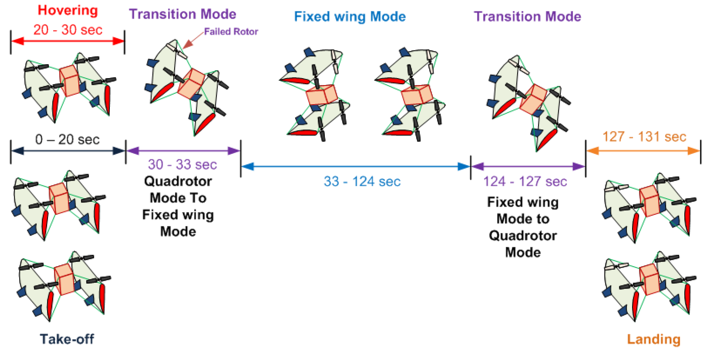
  • The biplane quadrotor is able to perform the transition maneuver even after the total rotor failure.
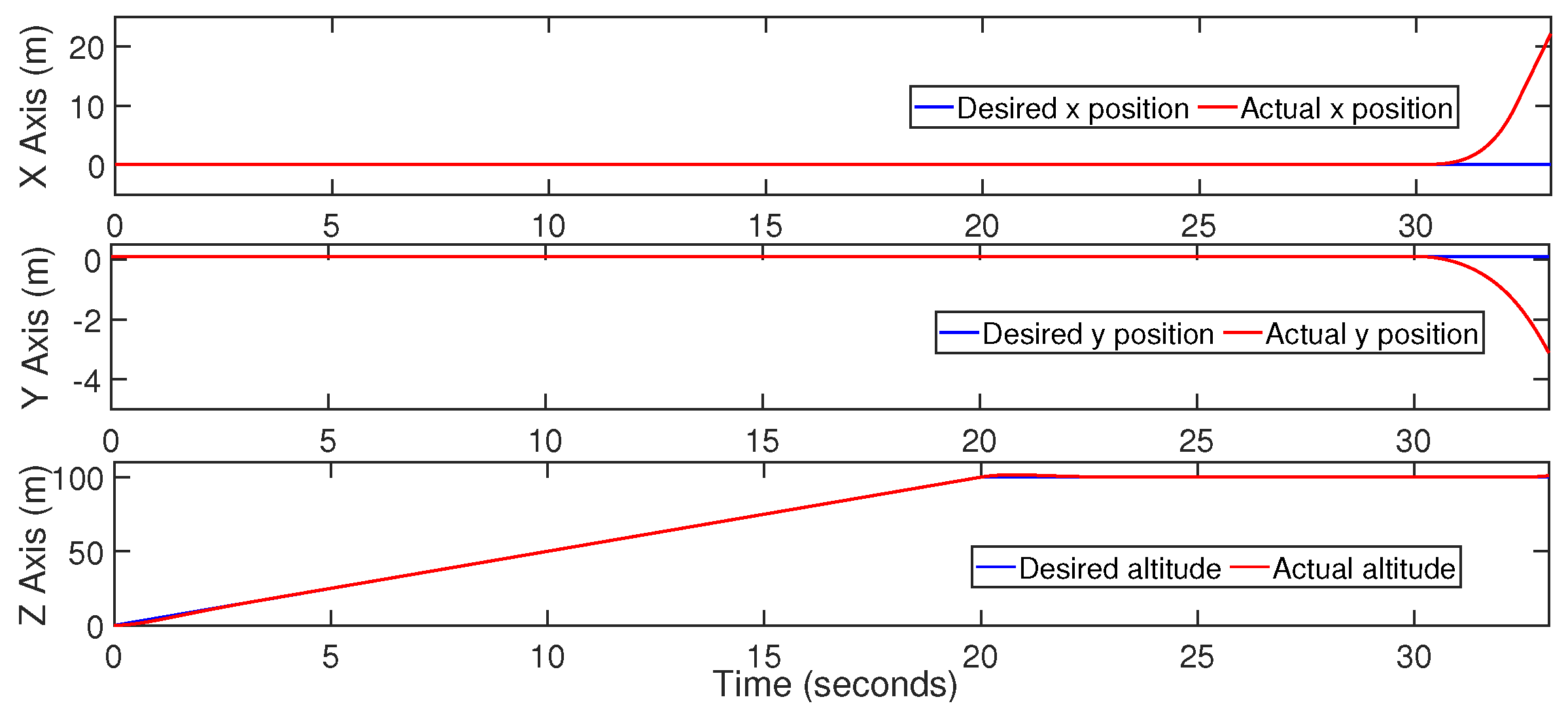
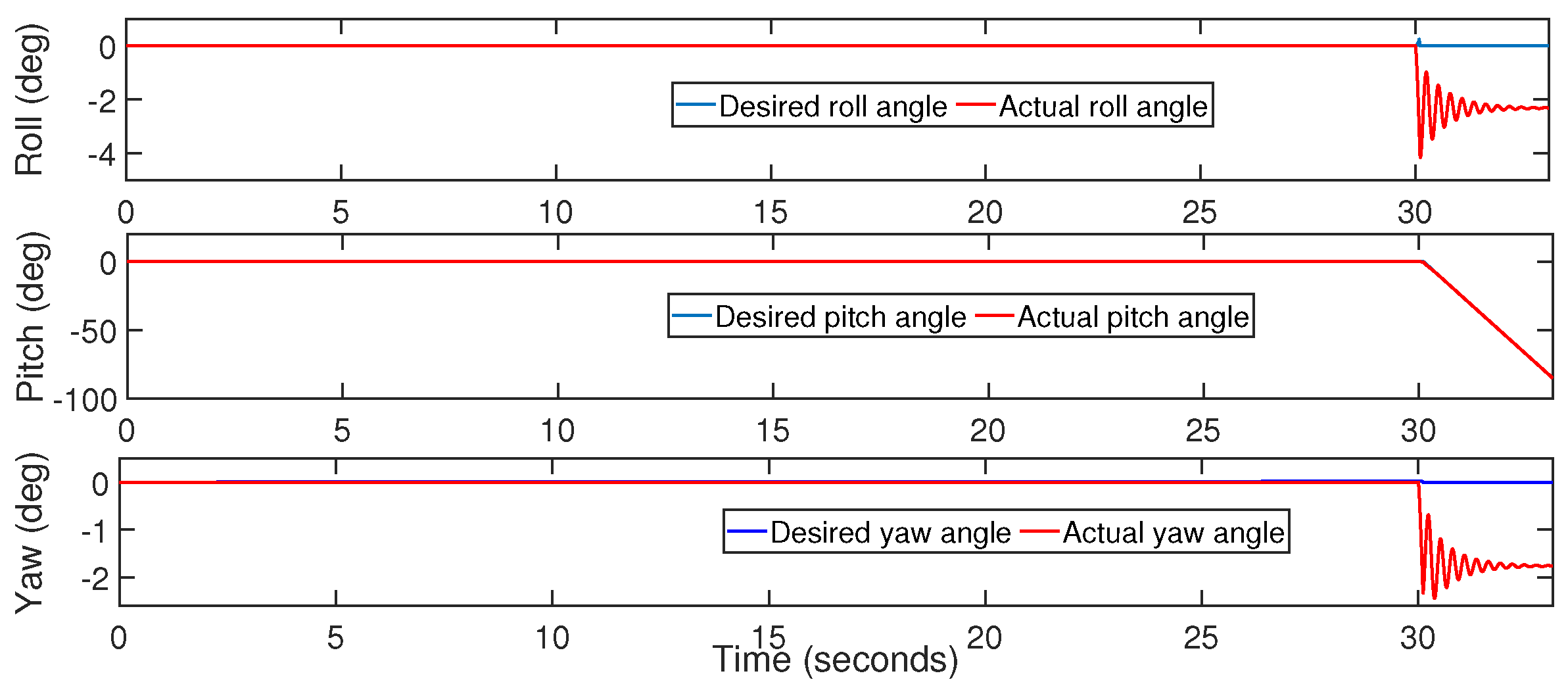
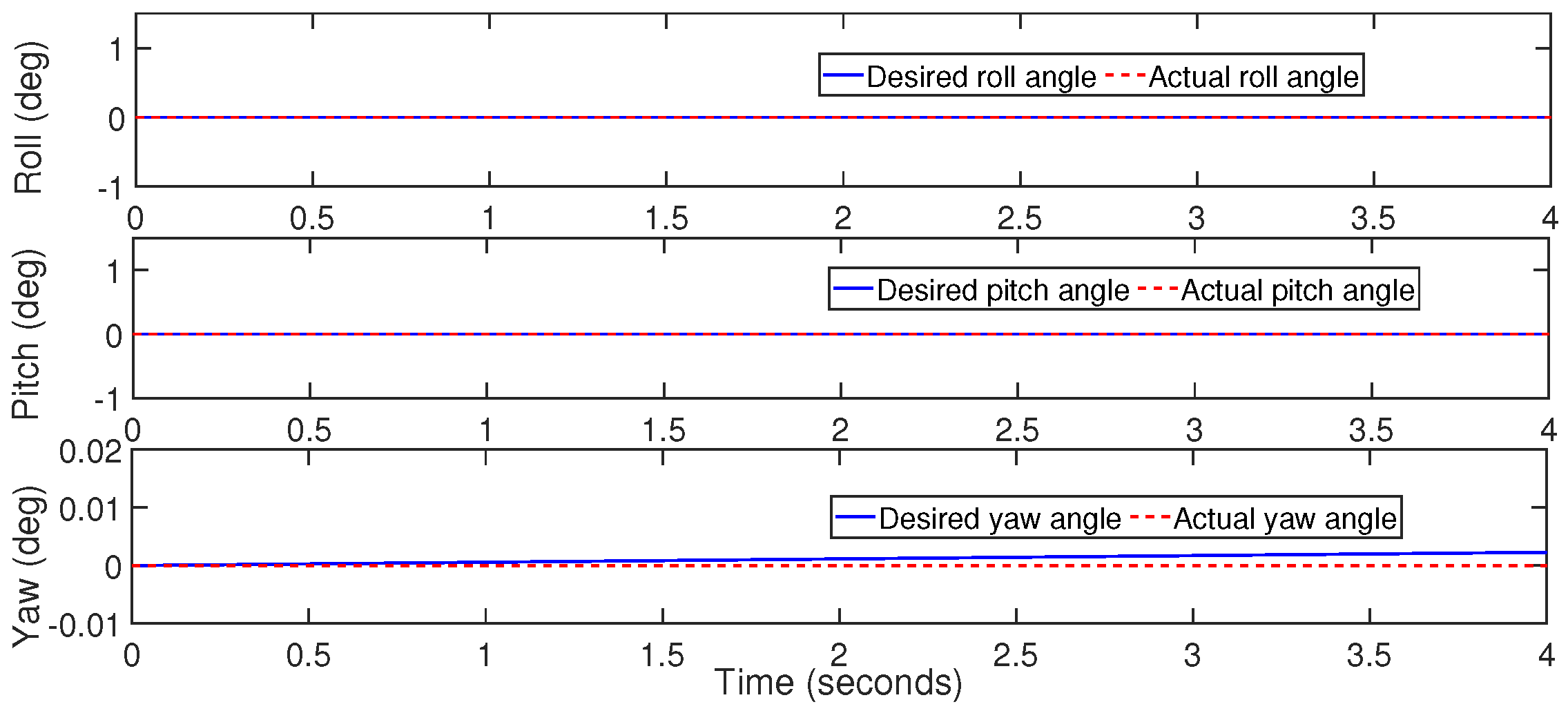
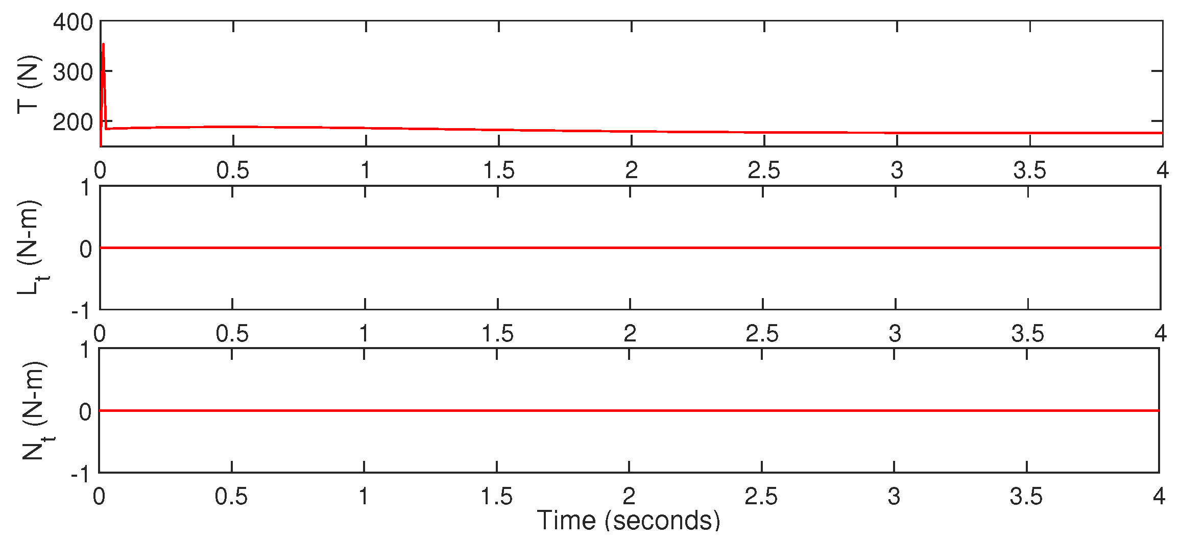
  • In fixed-wing mode, after the reallocation of the control signals, the desired altitude, roll, and pitch angles are tracked.
  • SJA is able to deliver the desired virtual deflection for controlling the pitching movement.
  • By using the adaptive inverse compensation scheme, non-linearity in the SJA is effectively compensated.
  • Based on the Lyapunov method, closed-loop stability of the overall control architecture is proven.

Author Contributions

Conceptualization, N.D. and D.D.; methodology, N.D. and D.D.; software, N.D.; validation, N.D. and D.D.; formal analysis, N.D. and D.D. and S.O.; writing—original draft preparation, N.D. and D.D.; writing—review and editing, D.D. and S.O.; supervision, D.D.; funding acquisition, S.O. All authors have read and agreed to the published version of the manuscript.

Funding

This research was funded by the European Regional Development Fund in the Research Centre of Advanced Mechatronic Systems project, grant number CZ.02.1.01/0.0/0.0/16_019/0000867 within the Operational Programme Research, Development and Education.

Institutional Review Board Statement

Not applicable.

Informed Consent Statement

Not applicable.

Data Availability Statement

Not applicable.

Conflicts of Interest

The authors declare no conflict of interest.

References

  1. Alioua, A.; Djeghri, H.; Cherif, M.E.T.; Senouci, S.M.; Sedjelmaci, H. UAVs for traffic monitoring: A sequential game-based computation offloading/sharing approach. Comput. Netw. 2020, 177, 107273. [Google Scholar] [CrossRef]
  2. Messina, G.; Modica, G. Applications of UAV thermal imagery in precision agriculture: State of the art and future research outlook. Remote Sens. 2020, 12, 1491. [Google Scholar] [CrossRef]
  3. Bravo, R.; Leiras, A. Literature review of the application of UAVs in humanitarian relief. In Proceedings of the XXXV Encontro Nacional de Engenharia de Producao, Fortaleza, Brazil, 10–13 October 2015; pp. 13–16. [Google Scholar]
  4. Specht, M.; Stateczny, A.; Specht, C.; Widźgowski, S.; Lewicka, O.; Wiśniewska, M. Concept of an Innovative Autonomous Unmanned System for Bathymetric Monitoring of Shallow Waterbodies (INNOBAT System). Energies 2021, 14, 5370. [Google Scholar] [CrossRef]
  5. Wang, D.; Xing, S.; He, Y.; Yu, J.; Xu, Q.; Li, P. Evaluation of a New Lightweight UAV-Borne Topo-Bathymetric LiDAR for Shallow Water Bathymetry and Object Detection. Sensors 2022, 22, 1379. [Google Scholar] [CrossRef]
  6. Dalwadi, N.; Deb, D.; Muyeen, S.M. Adaptive backstepping controller design of quadrotor biplane for payload delivery. IET Intell. Transp. Syst. 2022. [Google Scholar] [CrossRef]
  7. Chipade, V.S.; Abhishek; Kothari, M.; Chaudhari, R.R. Systematic design methodology for development and flight testing of a variable pitch quadrotor biplane VTOL UAV for payload delivery. Mechatronics 2018, 55, 94–114. [Google Scholar] [CrossRef] [Green Version]
  8. Ryseck, P.; Yeo, D.; Hrishikeshavan, V.; Chopra, I. Aerodynamic and Mechanical Design of a Morphing Winglet for a Quadrotor Biplane Tail-sitter. In Proceedings of the Vertical Flight Society 8th Autonomous VTOL Symposium, Mesa, AZ, USA, 26–28 January 2019. [Google Scholar]
  9. Sandiwan, A.P.; Cahyadi, A.; Herdjunanto, S. Robust proportional-derivative control on SO(3) with disturbance compensation for quadrotor UAV. Int. J. Control Autom. Syst. 2017, 15, 2329–2342. [Google Scholar] [CrossRef]
  10. Bouabdallah, S.; Noth, A.; Siegwart, R. PID vs LQ control techniques applied to an indoor micro quadrotor. In Proceedings of the IEEE/RSJ International Conference on Intelligent Robots and Systems (IROS) (IEEE Cat. No.04CH37566), Sendai, Japan, 28 September–2 October 2004; Volume 3, pp. 2451–2456. [Google Scholar] [CrossRef] [Green Version]
  11. Xi, L.; Zhu, Q.; Zhang, D. Sliding mode control design based on fuzzy reaching law for yaw angle of a Tail-sitter UAV. In Proceedings of the 2016 22nd International Conference on Automation and Computing (ICAC), Colchester, UK, 7–8 September 2016; pp. 238–243. [Google Scholar] [CrossRef]
  12. Zhang, M.; Liu, H.H. Tracking a Moving Target by a Fixed-wing UAV Based on Sliding Mode Control. In Proceedings of the AIAA Guidance, Navigation, and Control (GNC) Conference, American Institute of Aeronautics and Astronautics, Chicago, IL, USA, 10–13 August 2013. [Google Scholar] [CrossRef]
  13. Gambhire, S.J.; Kishore, D.R.; Londhe, P.S.; Pawar, S.N. Review of sliding mode based control techniques for control system applications. Int. J. Dyn. Control 2020, 9, 363–378. [Google Scholar] [CrossRef]
  14. Dalwadi, N.; Deb, D.; Kothari, M.; Ozana, S. Disturbance Observer-Based Backstepping Control of Tail-Sitter UAVs. Actuators 2021, 10, 119. [Google Scholar] [CrossRef]
  15. Dalwadi, N.; Deb, D.; Rath, J.J. Biplane Trajectory Tracking Using Hybrid Controller Based on Backstepping and Integral Terminal Sliding Mode Control. Drones 2022, 6, 58. [Google Scholar] [CrossRef]
  16. Wen, F.H.; Hsiao, F.Y.; Shiau, J.K. Analysis and Management of Motor Failures of Hexacopter in Hover. Actuators 2021, 10, 48. [Google Scholar] [CrossRef]
  17. Hou, Z.; Lu, P.; Tu, Z. Nonsingular terminal sliding mode control for a quadrotor UAV with a total rotor failure. Aerosp. Sci. Technol. 2020, 98, 105716. [Google Scholar] [CrossRef]
  18. Saied, M.; Lussier, B.; Fantoni, I.; Shraim, H.; Francis, C. Fault Diagnosis and Fault-Tolerant Control of an Octorotor UAV using motors speeds measurements. IFAC Pap. 2017, 50, 5263–5268. [Google Scholar] [CrossRef]
  19. Park, J.; Jung, Y.; Kim, J.H. Multiclass Classification Fault Diagnosis of Multirotor UAVs Utilizing a Deep Neural Network. Int. J. Control Autom. Syst. 2022, 20, 1316–1326. [Google Scholar] [CrossRef]
  20. Lin, C.E.; Shao, P.C. Failure Analysis for an Unmanned Aerial Vehicle Using Safe Path Planning. J. Aerosp. Inf. Syst. 2020, 17, 358–369. [Google Scholar] [CrossRef]
  21. Wang, X.; Sun, S. Incremental fault-tolerant control for a hybrid quad-plane UAV subjected to a complete rotor loss. Aerosp. Sci. Technol. 2022, 125, 107105. [Google Scholar] [CrossRef]
  22. Guzmán-Rabasa, J.A.; López-Estrada, F.R.; González-Contreras, B.M.; Valencia-Palomo, G.; Chadli, M.; Pérez-Patricio, M. Actuator fault detection and isolation on a quadrotor unmanned aerial vehicle modeled as a linear parameter-varying system. Meas. Control 2019, 52, 1228–1239. [Google Scholar] [CrossRef] [Green Version]
  23. Tahavori, M.; Hasan, A. Fault recoverability for nonlinear systems with application to fault tolerant control of UAVs. Aerosp. Sci. Technol. 2020, 107, 106282. [Google Scholar] [CrossRef]
  24. Chung, W.; Son, H. Fault-Tolerant Control of Multirotor UAVs by Control Variable Elimination. IEEE/ASME Trans. Mechatron. 2020, 25, 2513–2522. [Google Scholar] [CrossRef]
  25. Lu, P.; van Kampen, E.J. Active fault-tolerant control for quadrotors subjected to a complete rotor failure. In Proceedings of the 2015 IEEE/RSJ International Conference on Intelligent Robots and Systems (IROS), Hamburg, Germany, 28 September–2 October 2015; pp. 4698–4703. [Google Scholar] [CrossRef]
  26. Allahverdy, D.; Fakharian, A.; Menhaj, M.B. Fault-Tolerant Control of Quadrotor UAVs Based on Back-Stepping Integral Sliding Mode Approach and Iterative Learning Algorithm. Math. Probl. Eng. 2021, 2021, 1–15. [Google Scholar] [CrossRef]
  27. Yel, E.; Bezzo, N. A Meta-Learning-based Trajectory Tracking Framework for UAVs under Degraded Conditions. In Proceedings of the 2021 IEEE/RSJ International Conference on Intelligent Robots and Systems (IROS), Prague, Czech Republic, 27 September–1 October 2021; pp. 6884–6890. [Google Scholar] [CrossRef]
  28. Sharma, P.; Poddar, P.; Sujit, P. A Model-free Deep Reinforcement Learning Approach To Maneuver A Quadrotor Despite Single Rotor Failure. arXiv 2021, arXiv:2109.10488. [Google Scholar]
  29. Kim, M.; Lee, H.; Kim, J.; hun Kim, S.; Kim, Y. Hierarchical Fault Tolerant Control of a Hexacopter UAV Against Actuator Failure. In Robot Intelligence Technology and Applications 6; Springer International Publishing: Berlin/Heidelberg, Germany, 2022; pp. 79–90. [Google Scholar] [CrossRef]
  30. Dalwadi, N.; Deb, D.; Muyeen, S. Observer based rotor failure compensation for biplane quadrotor with slung load. Ain Shams Eng. J. 2022, 13, 101748. [Google Scholar] [CrossRef]
  31. Smith, B.L.; Swift, G.W. A comparison between synthetic jets and continuous jets. Exp. Fluids 2003, 34, 467–472. [Google Scholar] [CrossRef]
  32. Deb, D.; Burkholder, J.; Tao, G. Synthetic jet actuators and arrays: Modeling and control. In Adaptive Compensation of Nonlinear Actuators for Flight Control Applications; Springer: Singapore, 2021; pp. 11–41. [Google Scholar] [CrossRef]
  33. Tang, H.; Zhong, S. A static compressible flow model of synthetic jet actuators. Aeronaut. J. 2007, 111, 421–431. [Google Scholar] [CrossRef]
  34. Zong, H.h.; Wu, Y.; Li, Y.h.; Song, H.m.; Zhang, Z.B.; Jia, M. Analytic model and frequency characteristics of plasma synthetic jet actuator. Phys. Fluids 2015, 27, 027105. [Google Scholar] [CrossRef]
  35. Li, J.; Zhang, X. Active flow control for supersonic aircraft: A novel hybrid synthetic jet actuator. Sens. Actuators Phys. 2020, 302, 111770. [Google Scholar] [CrossRef]
  36. MacKunis, W.; Subramanian, S.; Mehta, S.; Ton, C.; Curtis, J.W.; Reyhanoglu, M. Robust nonlinear aircraft tracking control using synthetic jet actuators. In Proceedings of the 52nd IEEE Conference on Decision and Control, Firenze, Italy, 10–13 December 2013; pp. 220–225. [Google Scholar]
  37. Duvigneau, R.; Visonneau, M. Optimization of a synthetic jet actuator for aerodynamic stall control. Comput. Fluids 2006, 35, 624–638. [Google Scholar] [CrossRef] [Green Version]
  38. Deb, D.; Tao, G.; Burkholder, J.; Smith, D. An adaptive inverse control scheme for a synthetic jet actuator model. In Proceedings of the 2005, American Control Conference, Portland, OR, USA, 8–10 June 2005; Volume 4, pp. 2646–2651. [Google Scholar] [CrossRef]
  39. Deb, D.; Tao, G.; Burkholder, J.O.; Smith, D.R. Adaptive Compensation Control of Synthetic Jet Actuator Arrays for Airfoil Virtual Shaping. J. Aircr. 2007, 44, 616–626. [Google Scholar] [CrossRef]
  40. Deb, D.; Sonowal, S. Synthetic jet actuator based adaptive neural network control of nonlinear fixed pitch wind turbine blades. In Proceedings of the 2013 IEEE International Conference On Control Applications (CCA), Hyderabad, India, 28–30 August 2013; pp. 152–157. [Google Scholar]
  41. Trancossi, M.; Dumas, A. Coanda Synthetic Jet Deflection Apparatus and Control. SAE Tech. Pap. 2011, 2011. [Google Scholar] [CrossRef] [Green Version]
  42. Hong, M.H.; Cheng, S.Y.; Zhong, S. Effect of geometric parameters on synthetic jet: A review. Phys. Fluids 2020, 32, 031301. [Google Scholar] [CrossRef] [Green Version]
  43. Xu, X.; Zhou, Z. Study on longitudinal stability improvement of flying wing aircraft based on synthetic jet flow control. Aerosp. Sci. Technol. 2015, 46, 287–298. [Google Scholar] [CrossRef]
  44. Jabbal, M.; Liddle, S.; Potts, J.; Crowther, W. Development of design methodology for a synthetic jet actuator array for flow separation control applications. Proc. Inst. Mech. Eng. Part G J. Aerosp. Eng. 2013, 227, 110–124. [Google Scholar] [CrossRef]
  45. Li, C.; Zhang, T.; Yang, J. Attitude Control of Aircraft Using Only Synthetic Jet Actuators When Stall Occurs. IEEE Access 2018, 6, 37910–37917. [Google Scholar] [CrossRef]
  46. Post, M.; Corke, T. Separation Control on High Angle of Attack Airfoil Using Plasma Actuators. In Proceedings of the 41st Aerospace Sciences Meeting and Exhibit. American Institute of Aeronautics and Astronautics, Reno, NV, USA, 6–9 January 2003. [Google Scholar] [CrossRef]
  47. Shan, H.; Jiang, L.; Liu, C.; Love, M.; Maines, B. Numerical study of passive and active flow separation control over a NACA0012 airfoil. Comput. Fluids 2008, 37, 975–992. [Google Scholar] [CrossRef]
  48. Lee, D.; Nonomura, T.; Oyama, A.; Fujii, K. Comparison of numerical methods evaluating airfoil aerodynamic characteristics at low Reynolds number. J. Aircr. 2015, 52, 296–306. [Google Scholar] [CrossRef]
  49. Yousefi, K.; Saleh, R. Three-dimensional suction flow control and suction jet length optimization of NACA 0012 wing. Meccanica 2015, 50, 1481–1494. [Google Scholar] [CrossRef]
  50. Balakumar, P. Direct numerical simulation of flows over an NACA-0012 airfoil at low and moderate Reynolds numbers. In Proceedings of the 47th AIAA Fluid Dynamics Conference, Denver, CO, USA, 5–9 June 2017; p. 3978. [Google Scholar]
  51. Pranesh, C.; Sivapragasam, M.; Deshpande, M.; Narahari, H. Negative lift characteristics of NACA 0012 aerofoil at low Reynolds numbers. Sādhanā 2019, 44, 21. [Google Scholar] [CrossRef] [Green Version]
  52. Castelli, M.R.; Garbo, F.; Benini, E. Numerical investigation of laminar to turbulent boundary layer transition on a NACA 0012 airfoil for vertical-axis wind turbine applications. Wind Eng. 2011, 35, 661–685. [Google Scholar] [CrossRef]
  53. Mejia, O.D.L.; Moser, R.D.; Brzozowski, D.P.; Glezer, A. Effects of trailing-edge synthetic jet actuation on an airfoil. AIAA J. 2011, 49, 1763–1777. [Google Scholar] [CrossRef]
  54. Wei, Q.; Niu, Z.; Chen, B.; Huang, X. Bang-bang control applied in airfoil roll control with plasma actuators. J. Aircr. 2013, 50, 670–677. [Google Scholar] [CrossRef] [Green Version]
  55. Li, C.; Yang, J. Roll control using only synthetic jet actuators at high angle of attack. J. Aircr. 2016, 54, 371–376. [Google Scholar] [CrossRef]
  56. Hasegawa, H.; Obayashi, S. Active stall control system on NACA0012 by using synthetic jet actuator. J. Flow Control Meas. Vis. 2018, 7, 61–72. [Google Scholar] [CrossRef] [Green Version]
  57. Li, W.; Wang, W.; Huang, X.; Zhang, S.; Li, C. Roll Control of Morphing Aircraft with Synthetic Jet Actuators at a High Angle of Attack. Appl. Sci. 2021, 11, 505. [Google Scholar] [CrossRef]
  58. Tang, H.; Salunkhe, P.; Zheng, Y.; Du, J.; Wu, Y. On the use of synthetic jet actuator arrays for active flow separation control. Exp. Therm. Fluid Sci. 2014, 57, 1–10. [Google Scholar] [CrossRef]
  59. Montazer, E.; Mirzaei, M.; Salami, E.; Ward, T.; Romli, F.; Kazi, S. Optimization of a synthetic jet actuator for flow control around an airfoil. In Proceedings of the IOP Conference Series: Materials Science and Engineering; IOP Publishing: Bristol, UK, 2016; Volume 152, p. 012023. [Google Scholar]
  60. Jee, S.K.; Lopez, O.; Moser, R.; Kutay, A.; Muse, J.; Calise, A. Flow Simulation of a Controlled Airfoil With Synthetic Jet Actuators. In Proceedings of the 19th AIAA Computational Fluid Dynamics, San Antonio, TX, USA, 22–25 June 2009. [Google Scholar] [CrossRef]
  61. de Luca, L.; Girfoglio, M.; Coppola, G. Modeling and Experimental Validation of the Frequency Response of Synthetic Jet Actuators. AIAA J. 2014, 52, 1733–1748. [Google Scholar] [CrossRef]
  62. Geng, L.; Hu, Z.; Lin, Y. Thrust and flow characteristic of double synthetic jet actuator underwater. Ocean Eng. 2019, 176, 84–96. [Google Scholar] [CrossRef]
  63. Caruana, D.; Rogier, F.; Dufour, G.; Gleyzes, C. The Plasma Synthetic Jet Actuator, Physics, Modeling and Flow Control Application on Separation; Aerospace Lab. 2013, pp. 1–13. Available online: https://hal.archives-ouvertes.fr/hal-01184643/ (accessed on 13 June 2022).
  64. Singhal, C.; Tao, G.; Burkholder, J. Neural Network-Based Compensation of Synthetic Jet Actuator Nonlinearities for Aircraft Flight Control. In Proceedings of the AIAA Guidance, Navigation, and Control Conference. American Institute of Aeronautics and Astronautics, Chicago, IL, USA, 10–13 August 2009. [Google Scholar] [CrossRef]
  65. Ramos-Pedroza, N.; MacKunis, W.; Reyhanoglu, M. Sliding mode control-based limit cycle oscillation suppression for UAVs using synthetic jet actuators. In Proceedings of the 2015 International Workshop on Recent Advances in Sliding Modes (RASM), Istanbul, Turkey, 9–11 April 2015; pp. 1–5. [Google Scholar] [CrossRef]
  66. Swarnkar, S.; Parwana, H.; Kothari, M.; Abhishek, A. Biplane-Quadrotor Tail-Sitter UAV: Flight Dynamics and Control. J. Guid. Control Dyn. 2018, 41, 1049–1067. [Google Scholar] [CrossRef]
  67. Deb, D.; Tao, G.; Burkholder, J.O.; Smith, D.R. Adaptive Synthetic Jet Actuator Compensation for A Nonlinear Aircraft Model at Low Angles of Attack. IEEE Trans. Control Syst. Technol. 2008, 16, 983–995. [Google Scholar] [CrossRef]
Figure 1. Animated picture of biplane quadrotor.
Drones 06 00176 g001
Figure 2. Proposed control scheme.
Drones 06 00176 g002
Figure 3. Flow Separation during the Low AoA.
Drones 06 00176 g003
Figure 4. Control architecture flow diagram.
Drones 06 00176 g004
Figure 5. Proposed Control Architecture.
Drones 06 00176 g005
Figure 6. Block diagram of controller design for pitch angle tracking.
Drones 06 00176 g006
Figure 7. Biplane quadrotor modes and time duration.
Drones 06 00176 g007
Figure 8. Position and altitude tracking during quadrotor mode A.
Drones 06 00176 g008
Figure 9. Attitude tracking during quadrotor mode A.
Drones 06 00176 g009
Figure 10. Thrust and moments generated during quadrotor mode A.
Drones 06 00176 g010
Figure 11. Speed of each actuator during the quadrotor mode-a.
Drones 06 00176 g011
Figure 12. Position tracking during fixed-wing mode.
Drones 06 00176 g012
Figure 13. Attitude tracking during fixed-wing mode.
Drones 06 00176 g013
Figure 14. Moments generated during fixed-wing mode.
Drones 06 00176 g014
Figure 15. Thrust, virtual deflection and velocity during fixed-wing mode.
Drones 06 00176 g015
Figure 16. Speed of motor during fixed-wing mode.
Drones 06 00176 g016
Figure 17. Parameter Errors.
Drones 06 00176 g017
Figure 18. Position and altitude tracking during quadrotor mode B.
Drones 06 00176 g018
Figure 19. Attitude tracking during quadrotor mode B.
Drones 06 00176 g019
Figure 20. Thrust and moments generated during quadrotor mode B.
Drones 06 00176 g020
Figure 21. Rotor speed during the quadrotor mode B.
Drones 06 00176 g021
Table 1. Separation point ( x s / c ) at different AoA and Reynolds Numbers (Re) [48].
AoA ° Re = 1 × 10 4 Re = 3 × 10 4 Re = 5 × 10 4
00.8690.9790.869
1.50.7130.8320.781
30.5820.7130.770
4.50.4610.5750.674
60.3400.4290.556
7.50.1980.2090.409
9.00.0820.0560.115
Table 2. Parameter used for simulation.
ParametersValueParametersValue
I x 1.86 kg · m 2 I y 2.03 kg · m 2
I z 3.617 kg · m 2 Aspect ratio6.9
g9.8 ms 2 Wing Span2.29 m
Wing area (single)0.754 m 2 Mass (m)12 kg
Publisher’s Note: MDPI stays neutral with regard to jurisdictional claims in published maps and institutional affiliations.

