1. Introduction
The automotive market is looking for innovative brake solutions to reduce secondary emissions. This is mainly due to the need to safeguard people’s health and address the generation of PM
X, as braking systems are currently the main source of these emissions in the automotive sector [
1].
For this reason, our research team developed the ZEDS, a Zero-Emissions Driving System combining an electric motor (EM) with a magnetorheological brake (MRB) [
2]. The proposed solution maximizes the use of regenerative braking (RB), which is the capability of the EM to recover kinetic energy during deceleration, combining it with the MRB when this effect is not enough to stop the car or is not effective under specific driveline conditions [
3]. The MRB is a technology that uses a magnetorheological fluid (MRF), a smart fluid that acts as a non-Newtonian fluid when a magnetic field is applied [
4]. This paper does not address specific studies on the magnetic behavior of the fluid itself but focuses on the characteristics of the durability of the MRF.
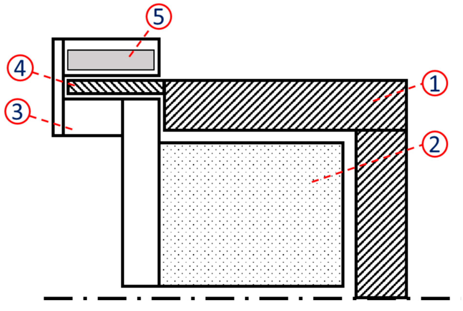
More specifically, the proposed design (
Figure 1) consists of an integration of the MRB with an in-wheel electric motor. The system is composed of coils in a stator, a rotor, and sealings capable of keeping the MRF within the specific gap, and the numbered parts are as follows:
Electric Motor Rotor.
Electric Motor Stator.
MR Brake Stator.
EM Rotor Protuberance.
Coils.
The MRF is set between the rotor protuberance (4) and the MR stator (3). The system is composed of an in-wheel electric motor that also provides vehicle traction.
The ZEDS works as follows:
- -
In the drive phase, the torque is provided by the electric motor, the coils are not energized, and the MRF has the characteristics of an oil (low viscosity).
- -
During the braking phase, depending on the brake request made via the driver’s brake pedal, a signal is generated that causes electrical power to be sent from the battery to the coils. When the current flows through the coils, a magnetic field proportional to the current intensity is developed and passes through the MRF.
The fluid, because of its magnetorheological properties, transforms into a semi-solid state and generates braking torque through its contact with the rotor [
5].
Some of the critical aspects of safety systems in vehicles are reliability and durability after use. Traditional braking systems have components, such as pads, that should be changed after 20,000 km and disks that should be changed after 50,000 km to ensure safe and reliable braking action. The thermal effects and wear of the parts are the main reasons for brake components’ need for maintenance [
6,
7].
There are few MRF durability analyses that can be found in the literature [
8,
9,
10], which mainly focus on technologies that are widely distributed in the market, such as clutches and dampers.
The abovementioned analyses underline the stability of the MRF under iterative working conditions and cycles, highlighting how the fundamental issues to be taken into consideration should be addressed regarding fluid separation and potential leakages from the chosen sealing solutions. It is possible to ensure that for shear applications, the MRF remains stable during operative cycles in applications such as clutches or dampers [
11,
12,
13].
For automotive braking applications, there are far fewer examples of benchmarking and experimental results, especially considering that in braking systems, such as the ZEDS, the MR fluid is consistently subjected to high thermal dissipation due to deceleration, and the power absorbed by the MRF itself is higher than that acting on damper applications.
For this reason, it is critical to evaluate its characteristic behavior after use to develop a consistent braking innovation with the MRF. Considering the literature on durability testing of the MRF [
14,
15,
16], it is possible to affirm that for specific applications like clutches or suspensions, the MRF has an operative life longer than traditional components and comparable to the applied tool. For this reason, we decided to evaluate a driving cycle equivalent to 100,000 km; while not an average lifespan, 100,000 km is often considered a significant milestone in a car’s life, characterized, as recommended by carmakers, as the moment for significant checks in the safety components, such as the belts or even the engine [
17,
18]. The traditional braking system has a mileage that is limited predominantly by the pads, whose operative life is limited between 20,000 and 25,000 km [
19], while, generally, carmakers recommend a disk change after 50,000 km [
20].
This paper investigates the durability of an MRF within an automotive braking system application by analyzing its performance under iterative cycling.
The aim is twofold:
To provide a comprehensive lifespan analysis, addressing a gap in our current knowledge of MRBs;
To evaluate the system’s endurance capabilities against traditional braking technologies.
2. Methodology
To evaluate the long-term performance of the MRF under conditions relevant to automotive braking, a comprehensive experimental methodology was employed.
A custom durability test bench (DTB) was specifically designed and constructed to subject the LORD MRF-132DG fluid to continuous rotational shear within a constant magnetic field generated by permanent magnets, simulating the operational environment of an MRB. The mechanical aging process was conducted for approximately 328 h of continuous braking action, ensuring that the total energy dissipated matched the equivalent energy absorption of 100,000 km on the WLTP-Brake cycle. A cooling system was employed to manage thermal loads and prevent overtemperature.
In parallel, separate thermal aging tests were performed on MRF samples using an oven at various temperatures and durations to isolate thermal degradation effects.
Following these aging protocols, the rheological properties of the three samples (baseline, durability-tested, and thermally aged fluids) were thoroughly characterized using an Anton Paar MCR 301 rheometer, measuring shear stress and viscosity as functions of the shear rate in both off-state (no magnetic field) and on-state (magnetic field applied) conditions.
Finally, Scanning Electron Microscopy (SEM) was utilized to conduct a microstructural analysis, examining the morphology and size distribution of the magnetic particles within the baseline and durability-tested MRF samples to understand any physical changes induced by the prolonged testing.
2.1. Functional Analysis of the Test Bench
Ensuring the durability and reliable performance of automotive brake pads is critical for vehicle safety. Consequently, various standardized tests and methodologies have been developed to evaluate their characteristics under controlled conditions in laboratory settings.
One foundational standard is ECE Regulation No. 90 [
21], which aims to ensure replacement brake pads perform comparably (within ±15%) to original equipment. While focused on performance equivalence rather than solely lifespan, its prescribed testing protocol involves procedures relevant to durability assessment, such as bedding-in routines, performance evaluations under various loads, cold condition checks, and speed sensitivity tests.
For direct wear evaluation, SAE J2707 provides a dedicated ‘Wear Test Procedure on Inertia Dynamometer for Brake Friction Materials’ [
22]. This recommended practice outlines a specific test methodology using an inertia dynamometer, including standardized conditioning (burnishing) protocols, specifically designed to quantify the wear rates of brake friction materials.
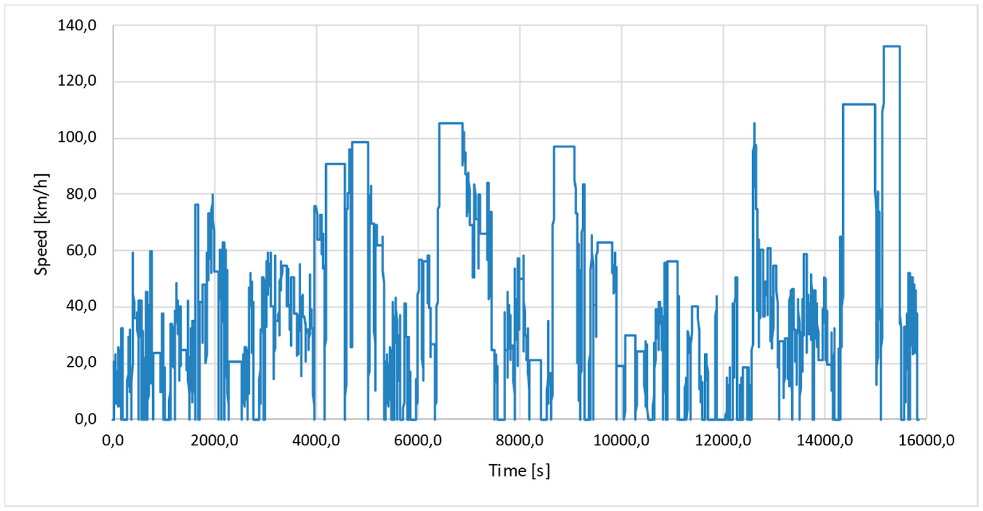
More recently, the development of the UNECE Global Technical Regulation (GTR) for Brake Emissions introduced a globally harmonized test cycle relevant to durability studies [
23]. Although its primary purpose is the measurement of brake wear particle emissions, the regulation specifies the WLTP-Brake [
24] cycle (
Figure 2) performed on a fully enclosed brake dynamometer, which subjects the brake system to standardized conditions inherently causing wear, making the procedure potentially useful for durability assessments alongside emissions measurement.
A specific methodology aimed at selecting friction materials is presented by Grygorcewicz [
25]. This outlines a two-stage process involving an initial screening using a small-scale IL-68 assess stand to measure friction, wear, and temperature, followed by more comprehensive full-scale dynamometer testing (using a Máot-3T dynamometer in the study) for the most promising material candidates.
These examples illustrate that dynamometer testing, often following standardized cycles and procedures (such as those in ECE R90, SAE J2707, or the WLTP-Brake cycle), is a central element in evaluating brake pad durability, typically focusing on measuring wear rates (by thickness or mass loss) and the stability of the friction coefficient under various conditions.
2.2. Test Bench Preliminary Performance Analysis
Starting from the specific data of the WLTP-Brake cycle, it is possible to evaluate the number of km driven in each cycle and the amount of energy absorbed by the braking actions, as reported in
Table 1. Considering the reference distance of 100,000 km for the endurance testing, the total amount of energy to be absorbed is equal to 247.7 kWh.
We decided to build a test bench capable of reaching the target energy absorption by the fluid using an electric motor to run a constantly braked MRB to simulate the cumulative run for reaching the absorption target.
In order to also have realistic behavior in terms of speed and torque, a scaled setup of the ZEDS, as shown in
Figure 1, is presented, which is capable of reaching an average rotating speed of 400 rpm. This is higher than the average speed presented by the WLTP-B cycle, which is equal to 36.2 km/h and, consequently, 330 rpm, considering a passenger vehicle application with a wheel radius of 0.291 m.
The energy absorption was evaluated considering the mechanical power data coming from the electric motor used as traction.
2.3. Test Bench Design
The design of the test bench was defined as a function of the chosen electric motor: ATO BLDCM 10 Nm [
26]. The constraints of the motor come from limitations in speed and torque, equal to 3000 rpm and 10 Nm, respectively. The chosen solution is to use a planetary gearbox with a 3:1 gear ratio, in order to have the expected rotating speed of 400 rpm on the rotor of the braking system and the availability for 30 Nm to be generated by the braking system, generating enough braking power to ensure the completion of the energy absorption test.
Considering the maximum torque available at the motor, the scaled brake was designed. We decided to generate a constant magnetic field using permanent magnets, N41, to generate a constant torque in time and reduce the complexity of the prototype.
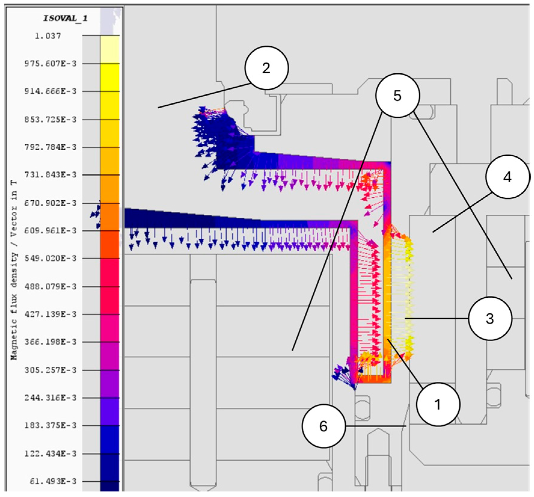
The simulation results of the generated magnetic field (deployed on Altair Flux) are reported in
Figure 3. It is possible to see that the MRF is magnetized perpendicularly to the rotational axis, allowing for an increase in the strength of the torque generated. The peak magnetic field reaches values around 900 mT, ensuring an optimal and homogeneous magnetization.
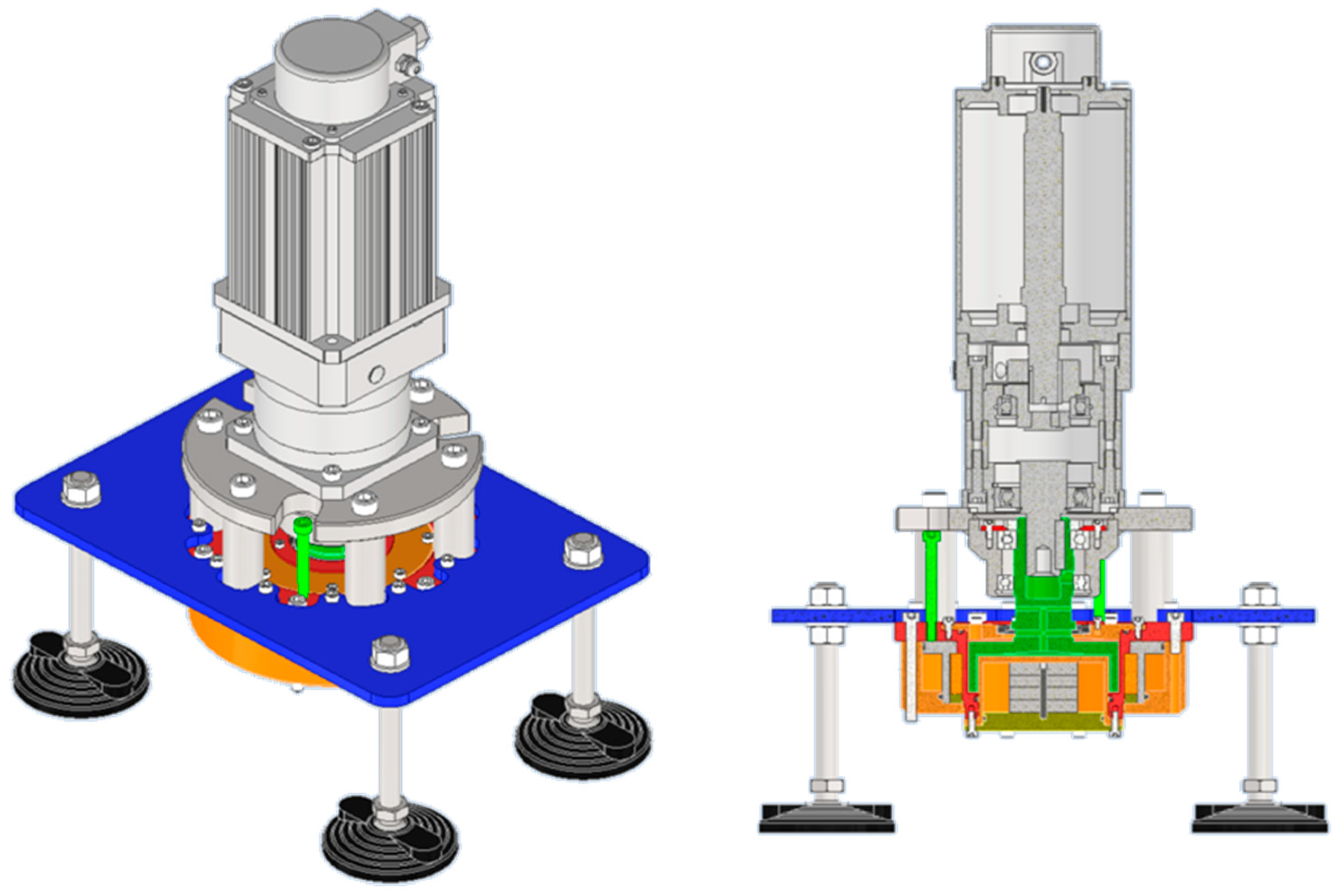
A cooling system was integrated into the test bench (reported in
Figure 4) to keep the temperature stable in the MRF and ensure the continuity of the durability tests. It is possible to see the electric motor in grey while, on the lower side, the braking system is positioned.
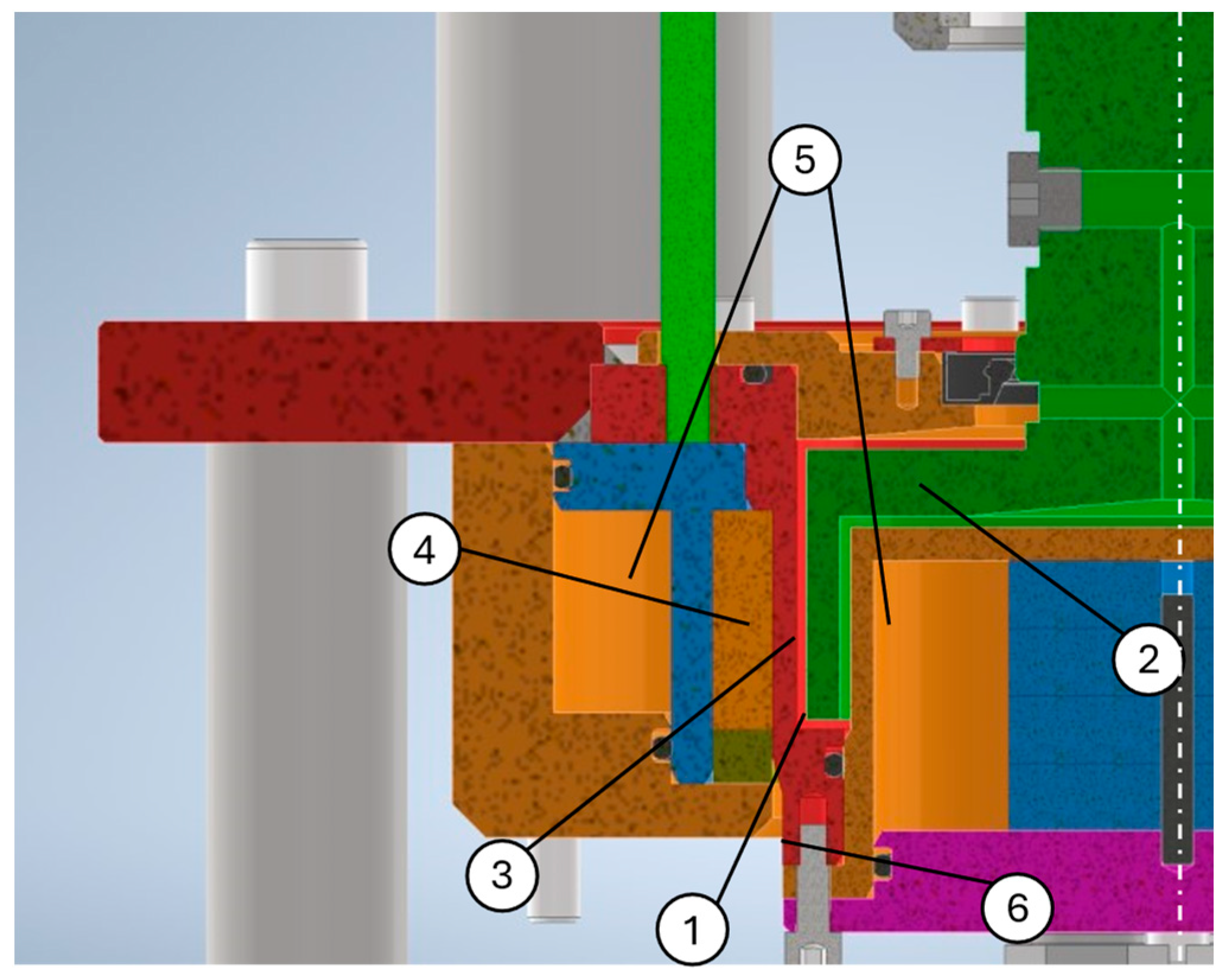
In
Figure 5, it is possible to see a cross-section of the scaled MRB, where the main components are as follows:
MRF Gap.
MRB Rotor, connected to the EM on the upper side.
MRB Stator, connected to the test bench structure.
Permanent magnet.
Cooling ducts.
Temperature Sensor.
The rotating axis is represented by the white dashed white line. The coolant, pumped from a chiller, is set to pass firstly through the internal section of the cooling ducts and then to the external duct outside the magnet.
The bench was produced in steel. The parts around the permanent magnet were produced in C40 iron to maximize the magnetic permeability and have consistent magnetization results.
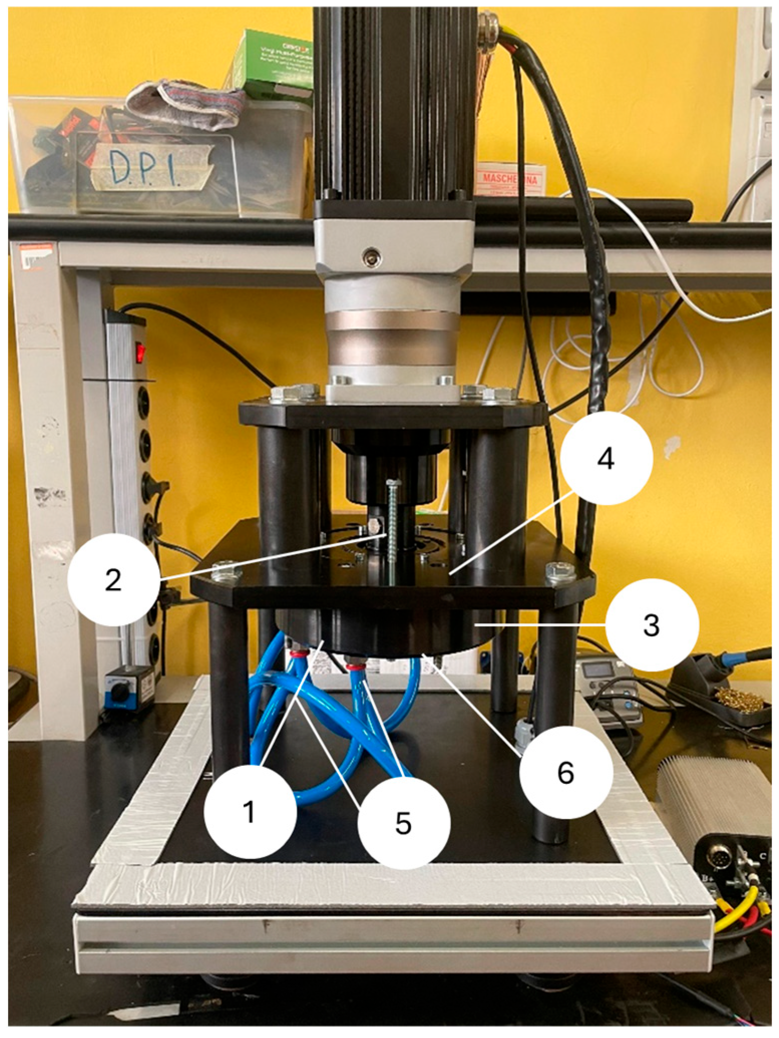
The final test bench is shown in
Figure 6. The structure was created to maximize accessibility and, at the same time, reduce vibrations through the working conditions.
3. Aging Test Procedure
Two main aging tests were performed:
- -
Durability test on the test bench, with rotation at constant speed and torque.
- -
Thermal aging, performed in a forced convection oven.
After each aging test, a sample of fluid was extracted, and both samples were evaluated with a rheometer to evaluate the rheological performance and compare them to the original fluid characteristics. The aim was to evaluate the operativity of the MRF after its standard operating life of 100,000 km.
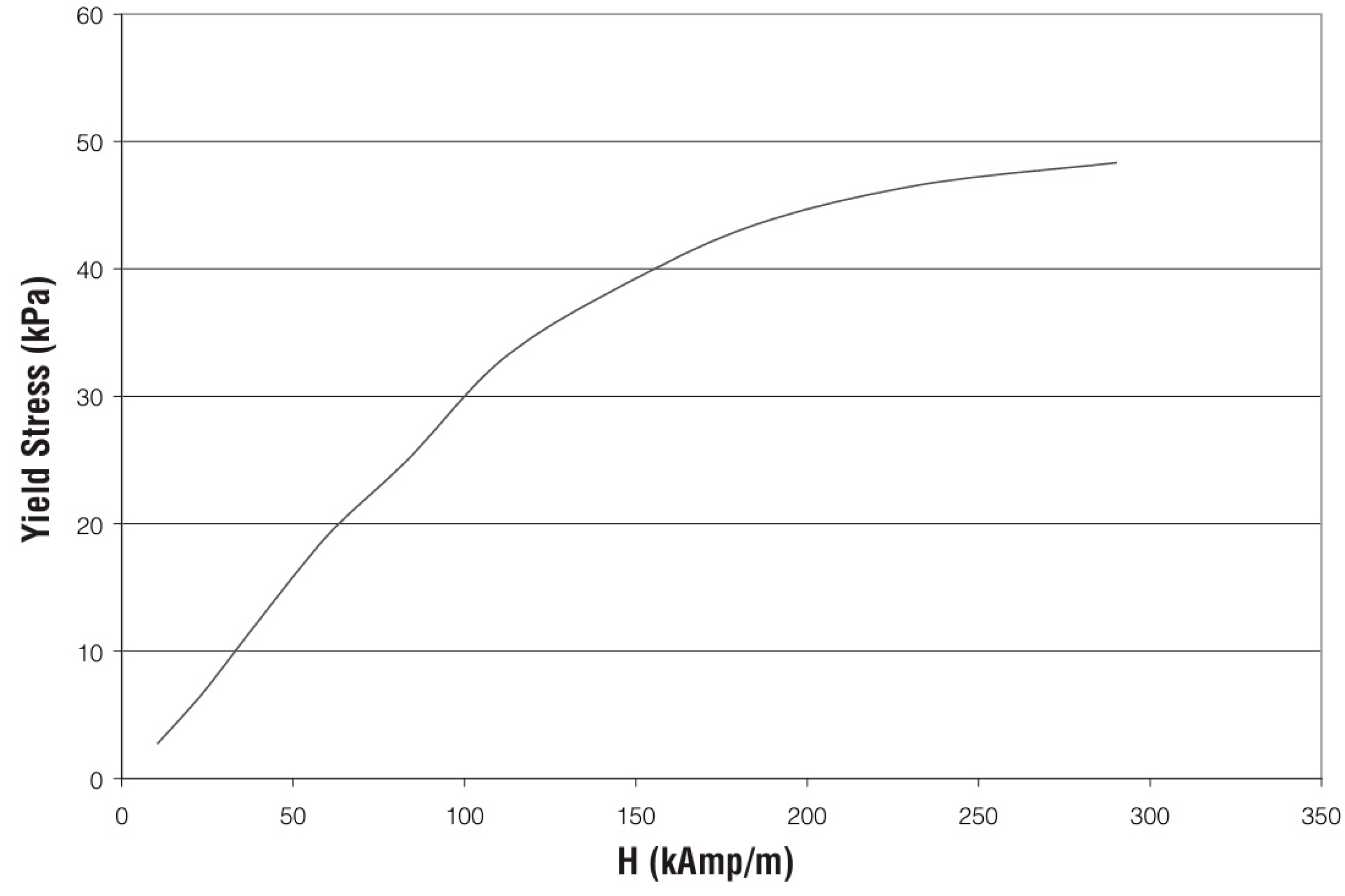
For this article, the commercial Lord’s MRF-132DG fluid was used for testing as it is one of the most well-known in the literature. The properties defined by the producer, in
Table 2 and
Figure 7, satisfied the parameters defined for a base magnetorheological fluid for brake application: an off-state viscosity below 500 mPa-s, a maximum yield stress above 45 kPa, and a temperature range from −40 to 140 °C.
3.1. Durability Test Bench Aging Procedure
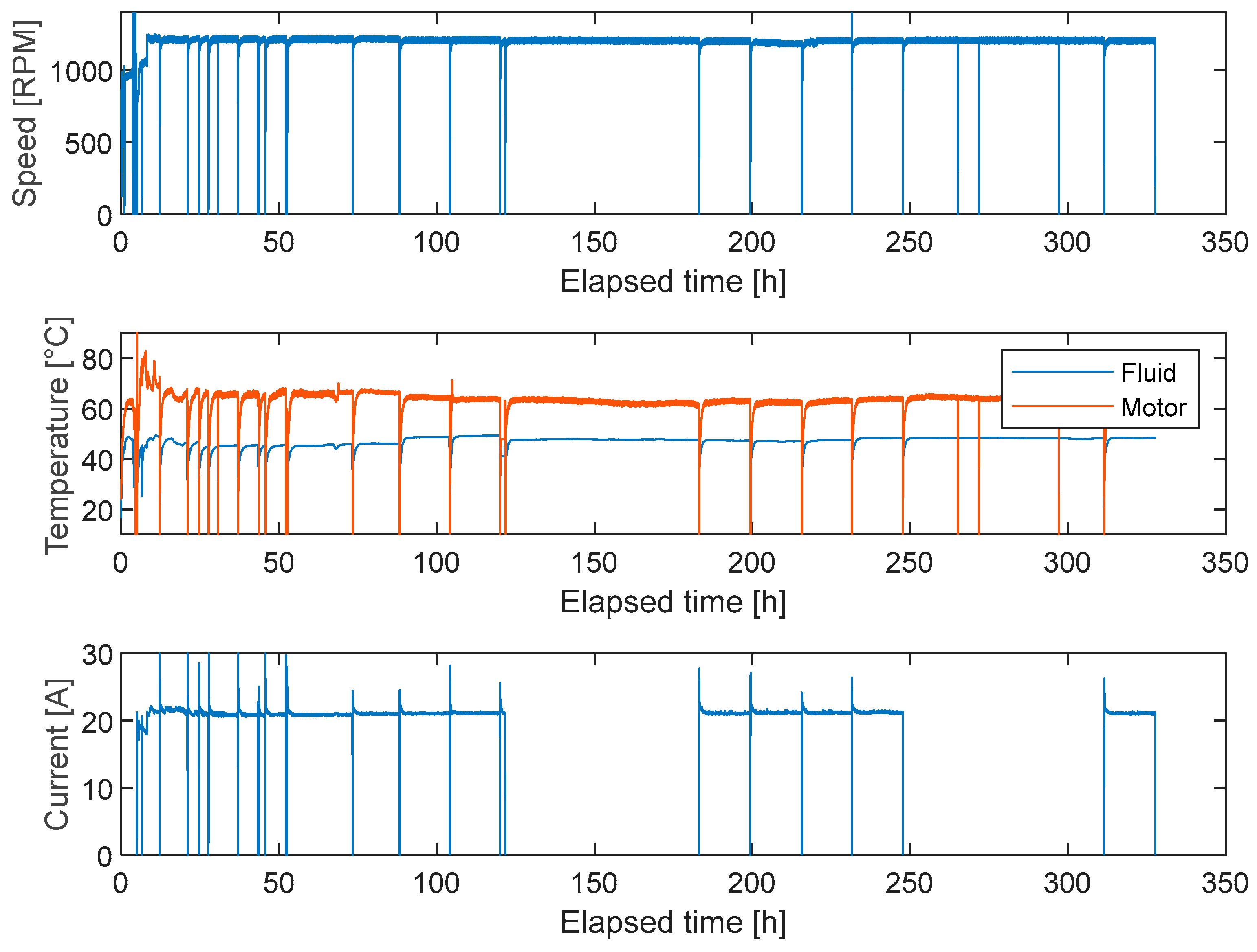
After some preliminary tests to evaluate the behavior of the test bench in action and integrating controllability strategies as safety procedures, the test bench started to run at a fixed rotating speed, as shown in
Figure 8, of 1200 rpm, equal to 400 rpm on the brake, due to the planetary gear transmission ratio. It is important to underline how the current data were lost in some segments because of issues in data recordings, but their values, being constant for the whole testing campaign, were evaluated as the average when needed for calculations.
The average value of current is equal to 21.4 A, while the efficiency of the electric motor is equal to 85%. Being supplied with a constant voltage, equal to 48 V, the average power dissipated by the brake is described in Equation (1):
where
P is the power generated, V is the voltage, I is the current, and
is the motor efficiency.
The results obtained were multiplied for the total time of the durability test, obtaining the results reported in
Table 3.
It is possible to see how the target power to be dissipated of 247.7 kWh was overcome, ensuring enough energy dissipation through the analysis to represent at least 100,000 km.
During the experimental tests, it was also possible, from a preliminary power analysis, to determine how the requested power by the EM was constant throughout the whole procedure, underlining how the braking capability of the fluid was stable for the whole test. To consistently evaluate the fluid behavior, it is necessary to check its capabilities inside the rheometer, a specific testing tool capable of evaluating fluid viscosity and shear stress to compare the fluid capability before and after the aging procedure.
3.2. Thermal Aging Procedure
In order to evaluate and compare the state of the MRF before and after use, even if the DTB is a consistent tool for simulating the behavior of the whole fluid life in terms of power dissipation, it is also important to consider the endurance of the fluid after a strong heating phenomenon since the DTB is kept at constant temperature well within the MRF operational limits. In fact, during braking operations, peaks of elevated temperature could be reached during strong braking maneuvers or iterative braking situations, such as, for example, during a long descent or even for repeating limit braking tests.
The aim of thermal gaining is to evaluate the fluid response even after long thermal stresses. For this reason, multiple samples of fluid were selected. To ensure homogeneity and prevent any errors caused by potential sedimentation, the MRF was thoroughly stirred for 10 min at 1400 rpm using a standard laboratory mixer before each experiment. This step was taken to eliminate any density mismatches and ensure consistent fluid properties during each analysis. Even minor variations in the concentration of metal particles can lead to significant changes in the rheological parameters of the fluid, potentially invalidating the experimental data.
The thermal aging was performed for multiple hours at different temperatures, where the MRF was placed into a forced convection oven. The testing list is reported in
Table 4.
The set of temperatures was chosen considering the limit temperature of the fluid of 130 °C, according to the datasheet [
27]. The time of the analysis was obtained from a series of bibliographical references [
28,
29].
4. Results
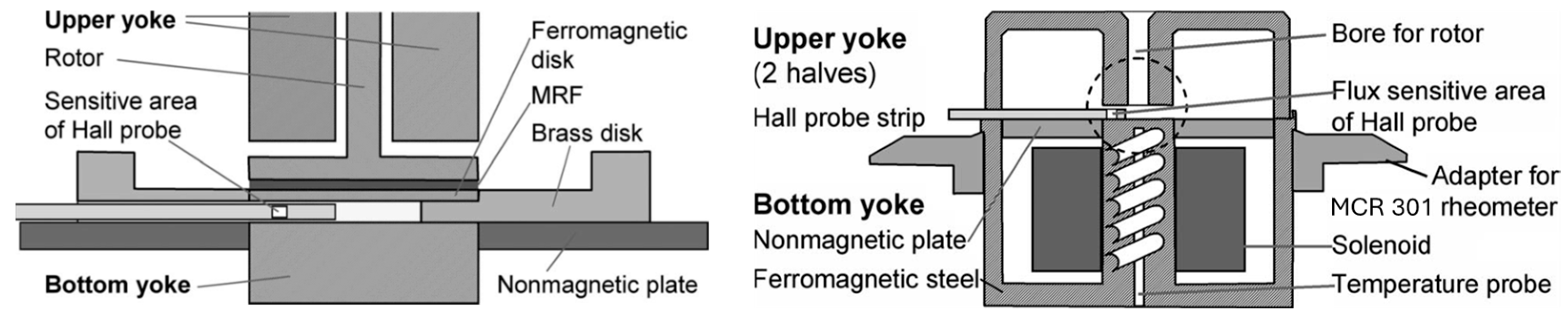
The on- and off-state rheological properties of the MRF were studied, with an Anton Paar MCR 301, in different measurement configurations. For the characterization with the field on, the rheometer was equipped with an MRD-70/1T magneto cell correlated with a parallel plate spindle geometry, as shown in
Figure 9. The validation of the measuring geometry, as well as the homogeneity in the field generated, is well established by many authors [
30,
31]. The cell consents to generate a homogeneous field up to 1T in the measuring plate region, using an upper yoke to close the circuit in proximity of the plate.
Temperature control is managed using an external fluid circulator (LAUDA Ecocline 207), which allows regulation across a wide range of temperatures (−30 °C to 90 °C). For the tests, however, since the magneto cell has an upper limit of 70 °C, a working temperature range of 10 to 65 °C was selected.
The testing procedure on the rheometer was previously defined to characterize the MRF specifically for the automotive braking application and to designate the significant parameters to be used in analysis [
32].
For this reason, a sample of 400 µL of the MRF was taken from the durability test bench after use, the thermally treated samples, and the baseline fluid.
The main values analyzed were as follows:
- -
Shear stress and viscosity vs. the shear rate at the off-state (no magnetization), aiming to evaluate the rolling resistance of the brake.
- -
Shear stress and viscosity vs. the shear rate at the on-state (maximum magnetization reached with 5 A in the rheometer), aiming to evaluate the rolling resistance of the brake.
The temperature in the rheometer was kept constant and at the standard values, in order not to affect the results of the tests.
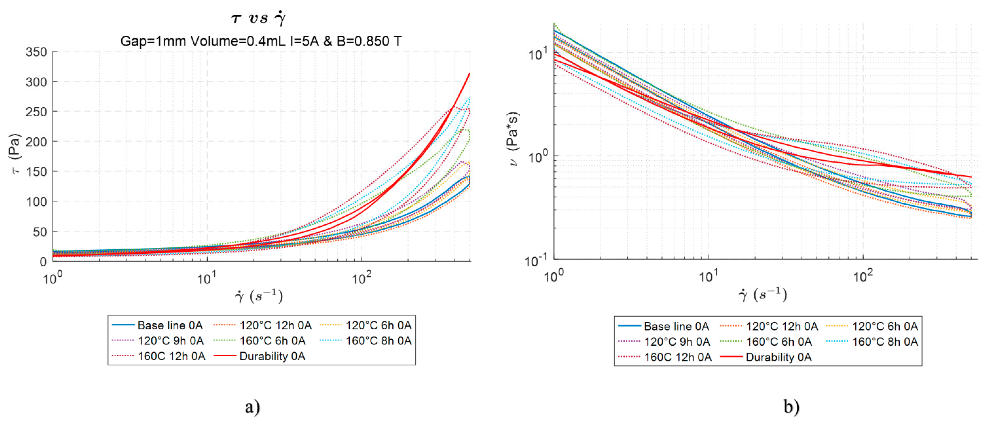
Figure 10 shows that in the off-state condition, with no magnetic field applied, no significant differences are visible between the baseline and the samples of the MRF, both the thermally stressed one and the one tested inside the DTB. Because the curves keep the same intensity in terms of shear stress, it is possible to affirm that no significant differences could be felt with the car during cruising. The durability sample is, on average, higher than the baseline one, but at a limited value of around 40%.
On the contrary, as shown in
Figure 11, at the maximum magnetization, the durability sample reaches around double the shear stress of the baseline fluid. All the other samples tested through thermal aging follow the baseline trend. In practice, this means the braking action available through the operative life of the fluid increases, considering the comparability between the power absorbed through the DTB and 100,000 km.
The explicit effect is that it is possible to affirm that after the durability procedure, the MRF does not lose any of its characteristics, allowing us to suggest that the solution could potentially be lifelong for the braking vehicle application. However, it is important to note that fluid behavior is not kept constant but increases its stresses at the end of durability tests. For this reason, we decided to proceed with an SEM comparison analysis to evaluate the microscopical changes the fluid sustained after the DTB.
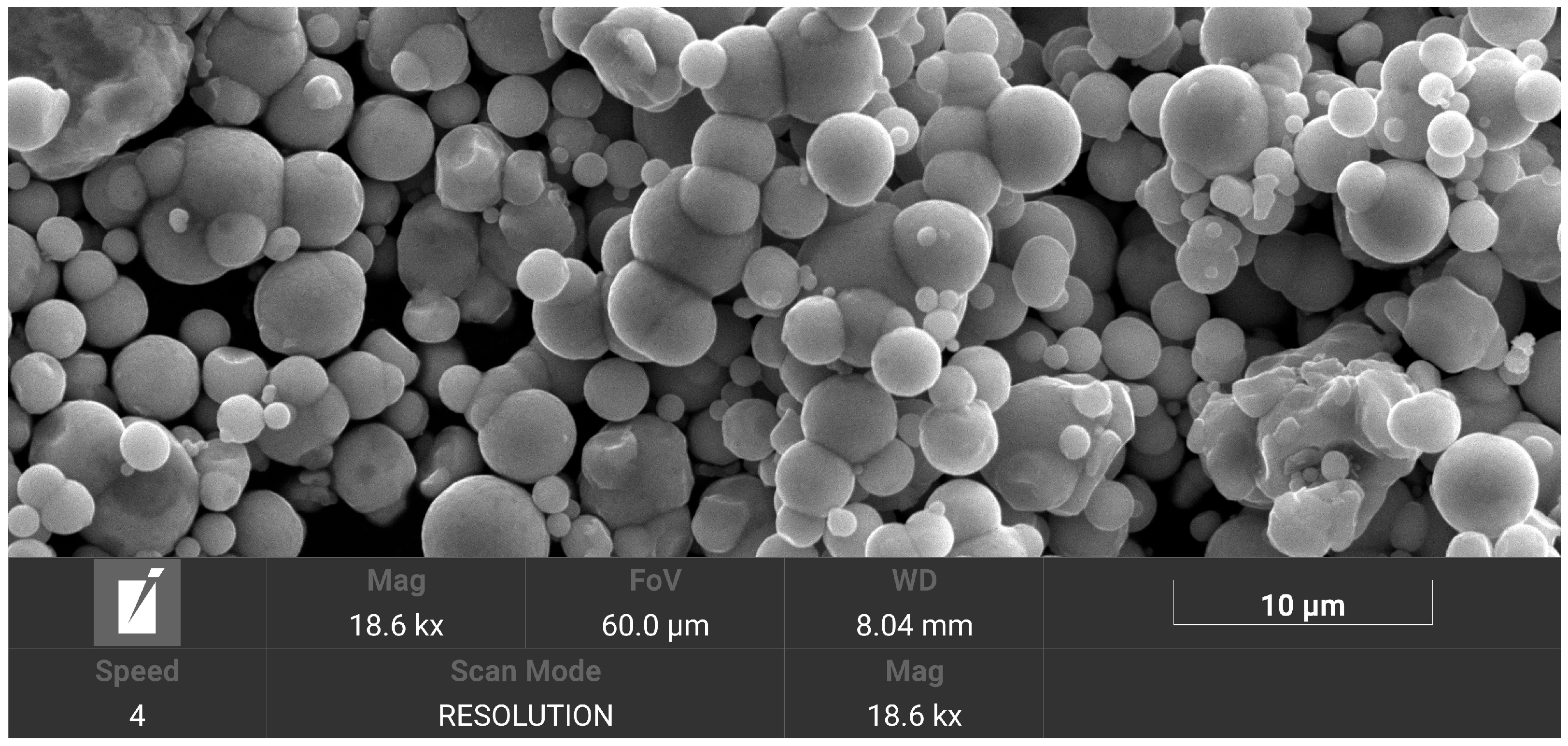
In
Figure 12, a representation of the Carbonyl Iron Powder of the baseline MRF is reported. From the image, it is possible to evaluate the average dimension of the magnetic particles equal to 2.43 µm. The shape of the particles is rounded, and, from the surfaces, it is possible to say that no significant imperfections can be evaluated.
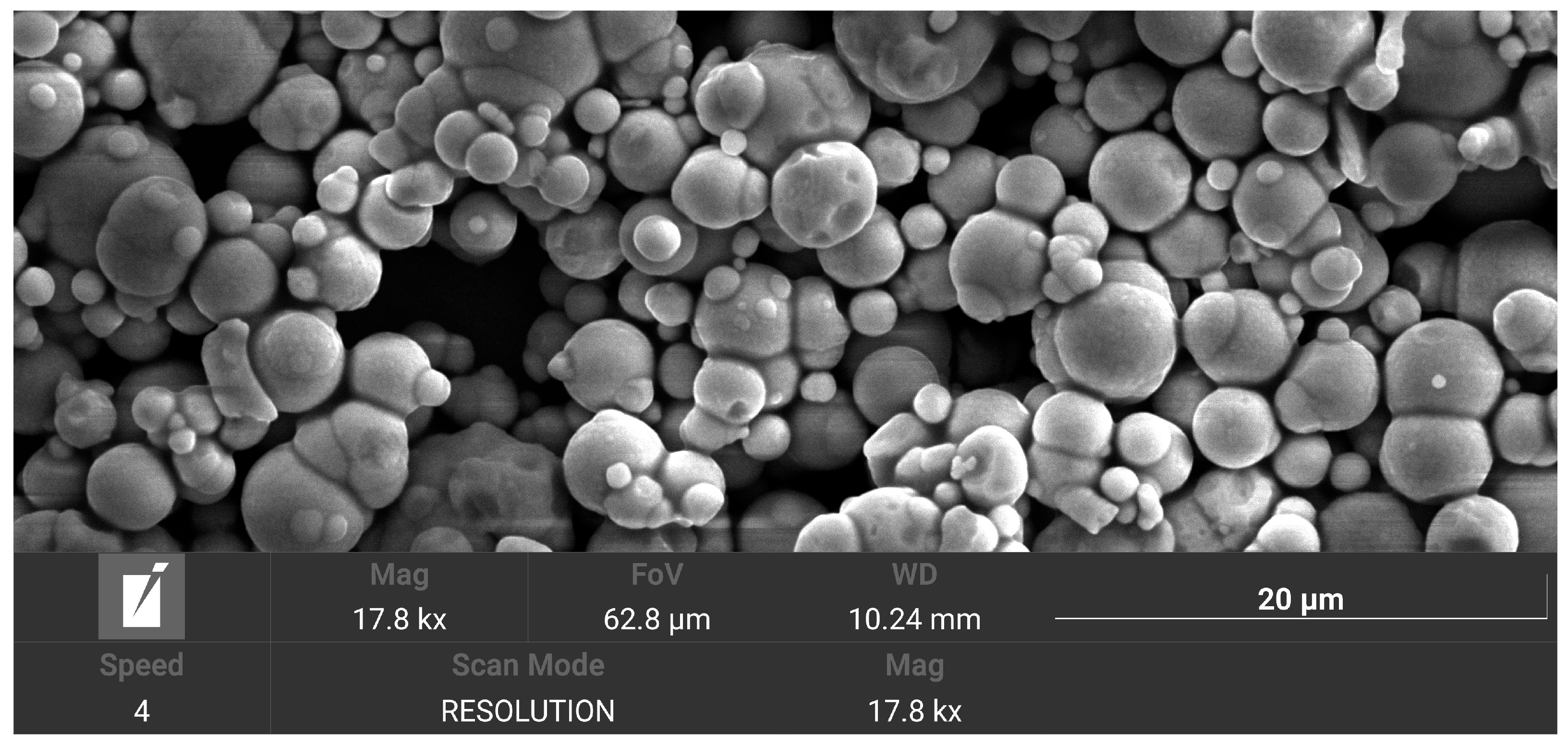
On the contrary, as it is possible to see in
Figure 13, the surfaces of the particles are imperfect and show surface irregularities and evidence of fragmentation. The shapes are not completely rounded, and the average is 1.23 µm.
By comparing
Figure 12 and
Figure 13, it is possible to evaluate qualitatively the higher number of smaller particles after the durability test.
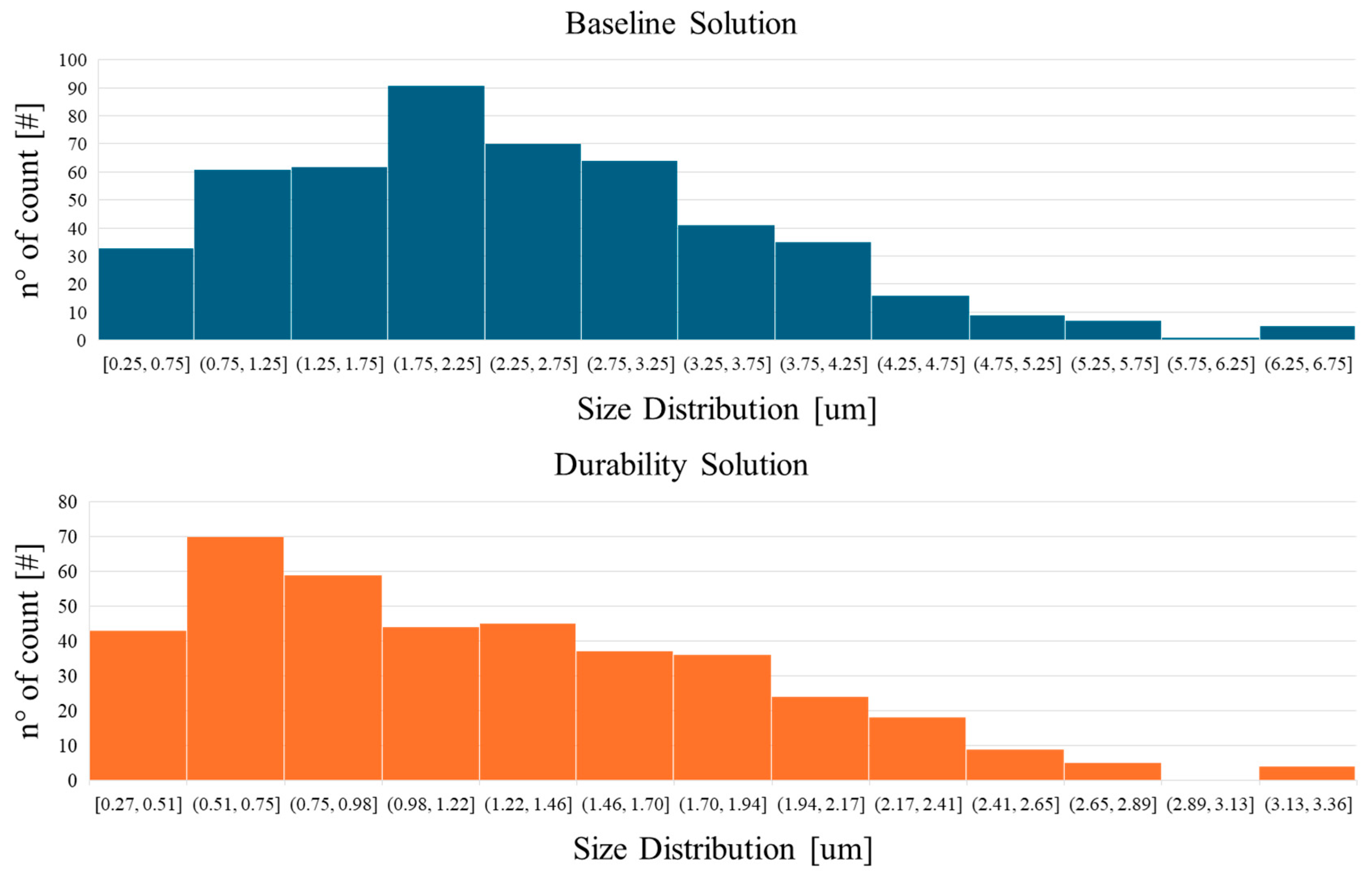
Quantitatively, it is possible to measure the radii particle by particle, as plotted in
Figure 14, where it is possible to see how the majority of particles after the durability test are smaller than before.
It is possible to affirm that during the DTB procedure, the carbonyl iron slowly started to break itself into smaller parts, increasing the percentage of nanoparticles dispersed in the fluid and modifying the microscopic structure of the whole fluid.
The dimension reduction effect has already been studied in the literature [
33,
34,
35] multiple times, indicating that adding nanoparticles can enhance the yield stress and potential torque of MR fluids, particularly when using optimized nanoparticle sizes and concentrations. The proposed mechanism often involves nanoparticles improving the structure or stability of the magnetic particle chains formed under a field. However, this is not a universal guarantee, as the specific materials, concentrations, and interactions within the fluid play a crucial role, and sometimes, improvements focus on stability rather than peak yield stress.
It is also possible to affirm that the results obtained from the rheometer analysis, as reported in
Figure 11, can be justified by a higher number of nanoparticles in the mixture due to partial erosion of the particles themselves.
We can conclude that through the duration of the test, representing the same amount of power dissipated through the fluid in 100,000 km, the deterioration does not jeopardize the performance, even improving the shear characteristics of the fluid. It is important to note that if the test had lasted longer, potentially, a point at which all the carbonyl iron particles could transition from micro to nano could have happened, changing the stability of the fluid and, consequently, affecting the braking capability. If the described phenomenon is longer than the vehicle’s operative life, the MRB solution could be considered for life. For this reason, further and longer durability tests will be performed.
5. Conclusions
This paper allows us to bridge a gap in the literature between aging analyses of MRFs and the possibility of using such smart fluids for lifelong automotive braking applications. The case was deployed because of the need to evaluate the advantages of a novel braking technology: the ZEDS.
The MRF underwent durability and thermal aging tests. Specifically, for the durability test, a specific test bench was deployed, aiming to subject the fluid to the same operating conditions of the automotive braking applications, both in terms of speed and power absorption.
The main performances of the MRF were analyzed using a rheometer before and after the durability analysis, and the results underline how the fluid does not lose its capabilities of generating torque after the aging process. The maximum shear stress at maximum magnetization reaches peaks higher than the double of the baseline condition, representing higher torques for the braking applications.
This effect comes from the generation of nanoparticles in between the fluid, increasing its capability of generating torque. The aging process, as analyzed, allows us to say that the MRB can potentially be considered a long-lasting braking solution that can equalize the vehicle’s life cycle and potentially avoid the need for maintenance for the end user.
Although it is important to proceed with further studies in order to validate the aging procedure, with on-the-road durability actions, at the same time, further and longer durability tests should be performed in order to define an energy absorption break-even, where the fluid particles are no more microparticles but are completely degenerated into nanoparticles.


 ,
, 

