1. Introduction
Industries such as oil and gas processing, mining, rayon textile manufacturing, paper and pulp mills, wastewater treatment, tanneries, and coke ovens are known to produce hydrogen sulfide (H
2S) as a by-product [
1,
2]. H
2S is a colorless, flammable, highly hazardous gas with a characteristic rotten egg odor. It exists as a gas at room temperature and is denser than air [
2,
3].
Table 1 presents some documented health effects associated with exposure to different concentrations of H
2S. Inhalation at concentrations exceeding 10 ppm can result in symptoms ranging from headaches to lung irritation, while concentrations of 100 ppm and above can result in loss of sense of smell and damage to major organs, and are considered to be immediately dangerous to life and health. Exposure to H
2S concentrations >500 ppm can result in death within minutes [
1,
2,
3,
4]. H
2S causes death by depriving the body of the oxygen (asphyxiation) needed for cellular activities through the inhibition of the iron (III) in the cytochrome oxidase and haemoglobin [
5,
6]. Apart from its toxicity, it is also a highly flammable gas with lower and upper explosive limits of 4.3% and 46%, respectively in air [
1,
7].
Naturally, H
2S can be formed from the anaerobic decomposition of organic matter buried underground or in shallow medium such as swamps [
8]. It can also coexist with oil and gas in subsurface reservoirs depending on the geological history and location of the reservoir [
9,
10]. Natural gas containing an appreciable quantity of H
2S (usually >16 ppm) is normally referred to as sour gas, while crude oil with >0.5% sulfur (including H
2S) is considered to be sour oil [
11]. Significant amounts of conventional sour oil and gas reserves are known to exist around the world. Several producers are shifting to the production of sour oil and gas reserves due to the continued depletion of sweet reservoirs and improving separation technology. Shale gas reserves, one of the major unconventional natural gas sources, are also known to contain H
2S that may not show up on initial well testing [
10].
Producing sour oil and gas reserves are more challenging than sweet reserves. Several potential issues such as corrosion, gas clathrate hydrate formation, as well as acid gas (CO
2 and H
2S) removal and disposal can be encountered and have to be handled [
11,
12]. The impurities such as H
2S, CO
2, and water must be removed in order to meet transportation pipelines and sale specifications [
11]. In order to optimize the production of sour oil and gas reserves, various issues encountered in production, processing, and transportation are the subject of research projects, most of which can involve testing with different concentrations of H
2S in highly specialized laboratories, such as those at the University of Calgary.
In order to assist with the safe transportation of sour gas, one of our current research subjects involves the experimental measurement of the thermodynamic formation conditions of H
2S and sour gas clathrate hydrates [
13]. Gas clathrate hydrates are solid, non-stoichiometric inclusion compounds that form in the presence of water at low temperature and high pressure [
14]. Hydrate formers include hydrocarbons (methane, ethane, and propane) and non-hydrocarbons (mainly H
2S and CO
2). Due to the extreme toxicity mentioned above, H
2S and sour gas hydrate formation conditions are not commonly studied. Laboratories designed to perform experiments with H
2S require implementation of effective hazard-control mechanisms. This paper discusses an H
2S leak on an autoclave vessel caused by a perfluorelastomer O-ring blistering while studying H
2S hydrates. We also report the emergency response and how the safety measures in place were used to prevent injury to the researcher, as well as leak detection, control, and containment in the surroundings of the H
2S.
Occupational health and safety in academic institutes have taken a place of importance in recent years, not only due to high-profile incidents but also the legal responsibility to comply with legislation such as the Alberta Occupational Health and Safety Act, Regulation and Code [
15,
16,
17].
The University of Calgary has an Occupational Health and Safety Management System (OHSMS) that clearly outlines the responsibilities of all employees, faculty, and students. The scope of the OHSMS includes hazard assessment and control, worker training, emergency management, and incident reporting and investigation. Regarding incident reporting, the OHSMS has an Online Accident Reporting System (OARS) which allows all registered laboratory users (e.g., researchers, students and principal investigators) to quickly and easily report safety incidents. The post-incident follow-up process focuses on identifying root causes and implementing corrective actions rather than disciplinary action to the individuals involved. Also, notable incidents and their corrective actions are anonymized and disseminated by the Environment, Health, and Safety (EHS) team for the University community to alert and educate personnel. This article serves to convey learnings beyond our institution and laboratory for external practitioners of H2S laboratories.
1.1. Preventive Actions and Hazard Control
Hazard controls are classified into four main categories [
1]. Firstly, the elimination of hazards from the workplace or substitutions to replace the hazardous materials/equipment with less hazardous ones is the most desired practice; however, this is not always possible. An example of an elimination process is the automation of a process and/or experiment to reduce worker exposure to toxic chemicals. Secondly, engineering controls can include designs and controls involved in the installation or modification of equipment/facilities in order to control a hazard at its source. An example is performing an experiment in a well-ventilated working area to control the emission of any leaked toxic gases. In our facility, one of the more prevalent engineering controls is to reduce the volume of the samples being investigated, i.e., there is a preference for 25 mL autoclaves versus the more common 0.5 to 3 L autoclaves. We note that the 25 mL and 50 mL autoclaves (Autoclave Engineers) use elastomer seals (Parker Seals), which are more susceptible to damage than metal seals, but can be used for seals that seal under dynamic conditions.
Thirdly, administrative controls centered on work-related practices and the worker can be implemented. They include the creation of standard operating procedures, hazard and operability study (HAZOP), worker training (including all necessary safety certifications), use of detectors to monitor toxic chemicals release/exposure, and any measure taken to ensure the safety of the worker. This type of control is normally used in association with other controls. Finally, personal protective equipment (PPE) are the last line of defense against hazard, they are usually worn to reduce or prevent exposure to toxic chemicals in the event of accident; examples are the use of safety glasses, lab coats, and the availability of self-contained breathing apparatus (SCBA) or supplied air breathing apparatus (SABA) in our facility [
1,
4].
1.2. Hydrogen Sulfide Detection and Monitoring
There are many technologies available for H
2S monitoring and detection/measurement; these include online tunable diode laser analyzers, fixed area monitors, test methods (Tutwiler, lead acetate paper, cadmium sulfate-iodometric titration, Doctor test), as well as portable and personal monitors [
7]. With the proper use of these technologies/combination of technologies, exposure to H
2S can be minimized/avoided. Laboratories and oil and gas facilities commonly use permanent electronic gas detection systems to alert workers to the presence/release of toxic gases in a particular area.
Depending on legislation and location, the permissible exposure limit to H
2S can vary from 1 to 10 ppm for a period of 8 h in a day. In most cases, the short-term exposure limit (15 min) is 15 ppm, while the concentration that should never be exceeded without the use of respiratory protection varies from 5 to 20 ppm [
1,
4,
7]. At 0.05 ppm, H
2S can usually be detected by its characteristic rotten-egg odor but concentrations greater than 100 ppm, however, can incapacitate the olfactory system within minutes, and subsequently could be fatal [
3]. Because of the importance given to the safety of workers and due to changing regulations, H
2S detection is critical for processes handling H
2S. Concentration levels are used to determine best response strategies; for example, to determine if a SCBA/SABA is required or if a complete site evacuation is necessary.
The choice of a detector depends mainly on the type of process; however, H
2S is commonly monitored using either a personal detector/monitor, normally worn by personnel; a portable area detector which can be carried by a worker to test for the presence of H
2S in a particular area; or fixed detectors permanently mounted in a specific area. Some detectors are capable of multiple gas detection, while others are gas-specific. Fixed detectors can alarm locally and/or remotely, while portable and personal detectors alert the worker locally to presence of H
2S by LED flashing, sound, and vibrations on the monitor. The efficiency of H
2S detection can be affected by many factors such as direction and velocity of wind on a particular day, or an impediment that may obstruct gas flow near the monitor [
18]. Our laboratory researchers are also fond of using lead acetate paper for even earlier indication of sulfides, using permanent detectors for detection within laboratories at all times, and wearing personal detectors.
1.3. Classification of Detectors
Most detectors can be classified based on the method of gas detection: the electrochemical, colorimetric, and optical methods are used. In electrochemical gas detectors, the gas flows into a permeable membrane containing an electrolyte with three electrodes (working, counter, and reference); the gas is reduced or oxidized at the working electrode. Most designs for electrochemical sensors use a diffusion barrier (driven by capillary action) to reduce the amount of gas contacting the working electrode for effective detection. The oxidation/reduction reactions result in a change in the potential between the working and counter electrodes. A driver circuit connected to the cell responds to the potential difference by delivering a current to compensate for the potential difference. The amount of current delivered is proportional to the gas concentration at a given time [
19]. Most metal oxide sensor surfaces can be regenerated with air, and their electrochemical cells possess a fixed quantity of reagent that must be replaced when consumed [
18].
The colorimetric gas detection method uses glass tubes packed with support materials such as silica or alumina to ensure narrow particle distribution. These types of tubes were first developed in the 1900s at Harvard University for carbon monoxide (CO) monitoring in confined areas, and later for H
2S. In this method, the gas is sampled using a piston/bellows pump through a glass tube containing a reagent (e.g., lead acetate) which reacts with the species of interest to produce a color that is related to its concentration at a given time [
20]. An example of an H
2S sensor which uses the colorimetric principle is an encaged roll of impregnated lead acetate paper tape in a window, and a color chart. On exposure to H
2S, a moist lead acetate paper will undergo a color change from white to brown. The rate of the color change and its intensity can be related to the concentration of H
2S.
In the detectors using optical methods, the concentration of the gas is measured by detecting the energy of absorption/emission at a specific wavelength based on the Beer–Lambert law expressed as [
21]
where
A is the absorption at a particular wavelength,
ε is the molar absorption coefficient,
c is the concentration, and
l is the optical path length.
Most gas species absorb or emit radiation at a distinct wavelength, which can be used to identify and quantify the concentration of gas species present. For example, a tunable diode laser spectrophotometer used for monitoring impurities such as H2S and H2O in a gas stream utilizes a diode laser as the light source to probe the analyte of interest. The analyte absorbs energy from the light and causes specific excitation of analyte molecules (vibrational excitation in this case). This response is converted to electrical signals which can be related to the concentration of the gas.
2. Materials and Methods
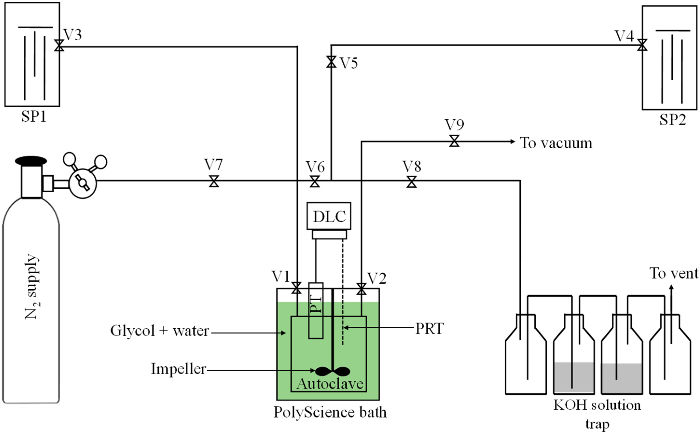
2.1. Experimental Setup
The experiments involved in the subsequent incident utilized a 25 cm
3 stirred Hastelloy C276 autoclave (Autoclave Engineers). It was coupled with a Keller PA-330X pressure transducer, a four-wire 100 Ω platinum resistance thermometer, and an impeller as shown in
Figure 1. Thus, there was an increased capability for rapid data collection beyond H
2S detection outside the vessel by lead acetate, permanent detectors, and personal detectors. The total internal autoclave volume with the pressure transducer headspace was measured to be ca. 46 cm
3. The autoclave cell is rated to withstand pressures up to 20.68 MPa and temperatures up to 423.15 K under 100% H
2S conditions. The vessel and the bottom portion of the transducer were submerged in a water–glycol refrigerated circulating bath, PolyScience PP07R-40, capable of controlling the temperature to within ±0.004 K.
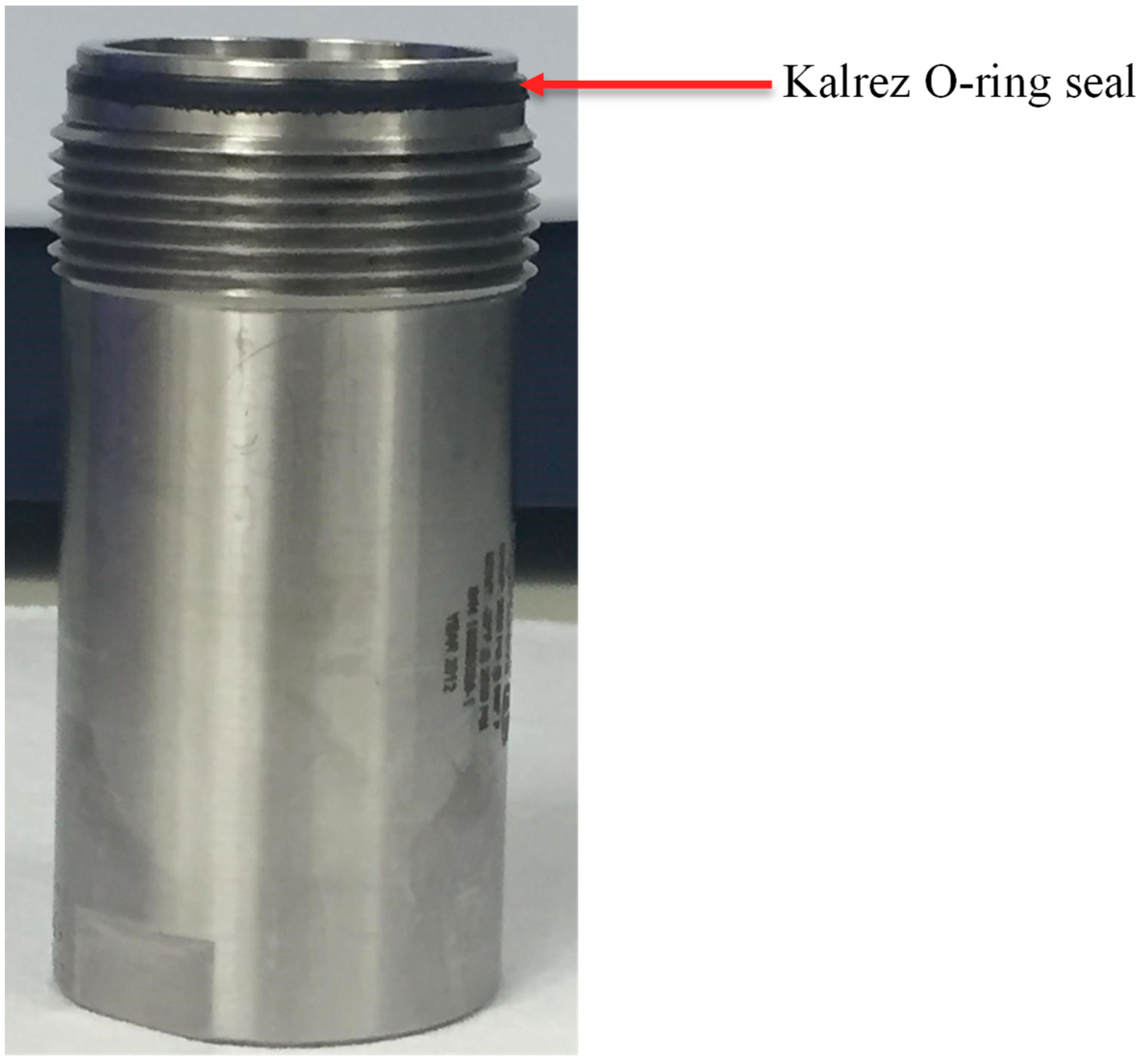
In order to prepare for an experiment, the lower part of the autoclave (shown in
Figure 2) is detached and sealed with a Kalrez-6735 perfluoroelastomer O-ring. The O-ring is rated to withstand temperatures up to 548.15 K under sour gas conditions. Wet H
2S compatible elastomer seals for this autoclave are supplied by Parker Seals, including perfluoroelastomers (Kalrez
® (4075 and 6375; Dupont)), ethylelene proplyelene, fluorinated fluorocarbon elastomers (HiFluor
®; Parker, Pleidelsheim, Germany), and isobutylene-isoprene (butyl IIR). Of these, only Kalrez
® is listed to withstand the higher temperatures anticipated by other experiments with this autoclave. We note that our laboratory has had experience with Kalrez
® and Chemraz
® (Greene Tweed, Kulpsville, PA, USA), EPDM and other elastomers. Metal seals cannot be used with this smaller autoclave, because the sealing metal surface is turned against the seal when tightening. Larger autoclaves often have seals which only compress without undergoing torque; however, H
2S volume would increase drastically.
The setup is connected to two Teledyne ISCO 260D syringe pumps; one containing H2S and the other containing H2O. Both pumps were used for delivering precalculated quantities of the fluid into the autoclave cell. The pumps were also sealed with graphite filled polytetrafluoroethylene seals as recommended by the manufacturers. The transfer lines between the pumps and the autoclave vessel were constructed from stainless steel tubing (SS-316), which was rated to pressure up to 50 MPa under sour gas conditions. Finally, a series of traps, two of which contained 20% KOH solution, were used for scrubbing effluent H2S during and after the experiments.
2.2. Experimental Procedure
All experiments and schematics were reviewed by four laboratory personnel before commencing measurements. This review was documented in a HAZOP, which was dispersed to all lab personnel and located at the entrance of the lab. Note that while the ventilated bay contained two permanent detectors, the experimenter also wore a personal H
2S detector. The procedure for this system was to begin by leak checking with pressurized N
2 and using a surfactant-based liquid leak detector on all fittings and connections (Snoop). The system was then evacuated using a vacuum of 2.5 × 10
−7 MPa for a period of 24 h. The setup was purged with gaseous H
2S at ca. 3 MPa three times before charging the autoclave to the desired pressure by opening valves V4 and V5, followed by valve V2, shown in
Figure 1. This lower purge pressure of H
2S also served as a secondary leak check as wetted lead acetate paper was placed on all fittings, and if the strip turned black, a reaction had occurred with H
2S, signifying that the fitting was leaking. The autoclave was filled with ca. 13 mL of liquid H
2S to allow for a liquid-gas system. The pure H
2S was thermally equilibrated for 6 h while stirring before adding degassed water via V3 and V1 to a target pressure of ca. 16 MPa. The system was then allowed to equilibrate to within ±0.005 MPa before inducing hydrate formation by reducing the temperature to a temperature T = 273.35 K for a period of 48 h.
After the complete hydrate formation as visualized by a pressure halt, the formed hydrate was then dissociated by increasing the temperature stepwise by 0.2 K increments. An example of a pressure–temperature profile for liquid water–hydrate–H
2S (g) and liquid water–hydrate–H
2S (l) phase boundaries experiments, their results, and a more detailed explanation of the experimental work can be found elsewhere [
13,
22]. After the completion of each measurement, the H
2S is released to (a) a dry gas trap, (b) a primary KOH scrubber, (c) a secondary KOH scrubber and (d) a final dry gas trap. The base scrubbers contain 20% KOH solution. Upon a completed measurement, the entire system is flushed with ultra-high-purity N
2. The experiment described here did not reach a completed measurement.
2.3. Safety Measures
As part of the administrative controls, every researcher in this laboratory undergoes mandatory safety training courses before working with H
2S. This includes institutional occupational health and safety orientation, laboratory safety practices, Workplace Hazardous Materials Information System (WHMIS) use, spill response, and respiratory protection as required by the University of Calgary [
23]. In addition, the H
2S Alive course, which was developed for the Alberta petroleum industry and is currently offered through Energy Safety Canada, is completed every three years [
24]. Research workers are fit-tested for the appropriate breathing apparatus masks at least every two years, as per the National Standard of Canada CAN/CSA-Z94.4-18 [
25]. Drills on the use of breathing apparatus, as well as refreshing procedural knowledge on the gas detection systems, are done on an annual basis.
All experiments involving H
2S are conducted during the working hours, only when other qualified persons are present. All experimental setups and H
2S supply tanks are housed in separate well-ventilated bays, with H
2S levels monitored continuously with fixed Honeywell E3Point detectors, which are linked to a Honeywell VA301C control panel equipped with data-logging capability through the use of an SD card. Detectors are located at ca. 35 cm above the floor in all bays. The low- and high-level response alarms for H
2S are set at 5 and 15 ppm, respectively, in accordance with the University of Calgary’s H
2S Code of Practice standard [
26]. In cases of any alarms, the fixed detectors sound the alarm locally to alert the workers present in the laboratory. When H
2S concentrations reach high alarm levels, the detectors also relay a signal through the building management system to alarm occupants in our research group administrative office and in the building security office, which is staffed at all times.
The delivery of H2S from supply tanks located in a cylinder storage room is controlled with air-operated valves (AOVs) for the safe transfer of H2S to experimental area when needed. The AOVs are programmed to shut off automatically in cases of any alarms, or power outage, in order to greatly limit the amount of toxic gases flowing to the apparatus in the event of an emergency.
Standard operating procedures and HAZOP for this experiment were also reviewed with the principal investigator and other researchers before starting the research. Potential risks associated with the experiment were discussed along with the recommendation of possible approaches and solutions. Some of the specific hazard controls relating to this experiment include: (i) keeping the ventilated bay door closed, except when entry is required during charging and evacuating the autoclave, (ii) automating the experiment through the use of the LabVIEW program, so as to reduce the need to enter the bay, (iii) keeping less than 100 cm3 of liquid H2S in the ISCO high-pressure syringe pump (maximum volume = 266 cm3) at any time, (iv) always having two knowledgeable people present during charging or depletion of the apparatus, both of whom must be wearing PPE and handheld detectors.
Again, we note that, because we cannot avoid using liquid H2S in this case, the primary safety control is to limit the volume of liquid H2S being used. In our opinion, there are many industrial and academic laboratories which choose to conduct experiments with large autoclaves (>300 mL), where the potential for exposure could have been mitigated. The size of these autoclaves seems to be historical in many cases.
2.4. Emergency Shutdown Procedure and Accident Response
There are two types of leaks that can occur in this experiment. Firstly, a minor leak which is <1 ppm and does not register on the personal or wall detectors. In most cases, this type of leak can be fixed and corrected without venting the content of the autoclave cell and syringe pump containing H2S. If it is safe to do so, the manifold around the leaking gas fitting is first vented and evacuated before correcting the leaks. Again, the use of lead acetate paper for detection is the method for detecting minor leaks.
The second type of leak is a major leak that sets off the personal and portable monitors’ alarms. In this scenario, both the experimental bay and laboratory doors must be shut immediately (or may already be closed) and everyone in the immediate laboratory must evacuate to a safe distance to assess the situation and determine the best response strategy. Two certified individuals masked with SCBA/SABA and PPE may enter the bay to open the necessary valves to scrub the H2S into the KOH solution when this is possible and deemed necessary. Again, through limiting volumes, the design is aimed at having a major leak reach safe levels in less than a minute without intervention (air exchange only).
3. Safety and Emergency Response during an H2S Leak Incident
As part of the procedure for evacuating the H2S upon completion of an experiment, the temperature is normally increased above the hydrate stability temperature (>308.15 K) in order to melt the formed hydrate while keeping the door of the ventilated bay closed. Following such a procedure, while increasing the temperature to 323.15 K, a Kalrez-6735 O-ring seal blistered on the autoclave vessel containing 11.37 g of H2S at a pressure p ≈ 3.8 MPa. This led to an immediate release of the H2S into the ventilated bay, which triggered the alarm of the fixed Honeywell E3Point detector installed in the experimental bay. The detector registered a concentration of more than 50 ppm H2S (over the detector’s maximum). All the occupants in the laboratory area exited immediately to a safe distance down the hall where the SCBAs were located, and the laboratory door was closed.
The incident was assessed to discuss the best response strategy. A BW GasAlert Extreme H2S portable monitor was left outside the closed laboratory door to monitor the level of H2S; the monitor did not detect any H2S during the response. Due to the low volume of H2S contained in the autoclave and not detecting any H2S outside of the closed laboratory door, it was decided to wait for some time to allow the ventilation to refresh the air within the bay before entering. Two workers then entered the laboratory with SCBA, while a third person observed from outside the laboratory. By the time they entered the laboratory (10–15 min after the leak event), all H2S had vented and readings were less than 5 ppm on the fixed monitor inside the bay. The handheld detector placed outside the laboratory did not register any concentration of H2S. Neither of the bays neighboring the bay in question went into alarm, indicating that the H2S was contained and vented properly. H2S was not detected in the building plenum during the event (there is a permanent detector at the building outlet and very large dilution factor).
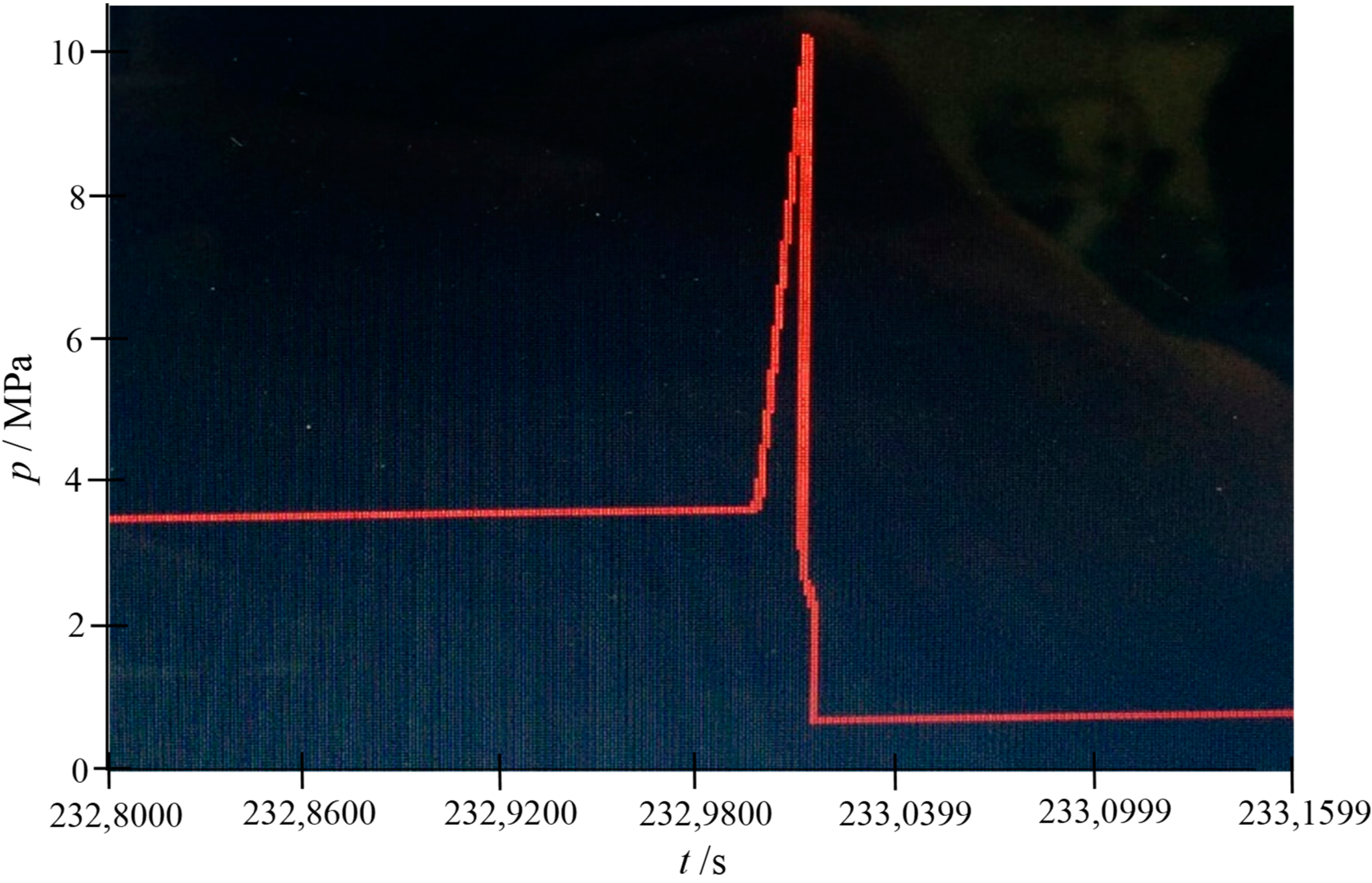
Figure 3 shows the pressure versus time profile of the autoclave heating that resulted in the leakage. The pressure indicated that the seal broke at ca. 10 MPa. The initial sharp rise in pressure was a result of the sudden melting of the hydrate and corresponding release of H
2S from its encaged cavities. Following the hydrate gas release, the pressure dropped rapidly to atmospheric within 30 s.
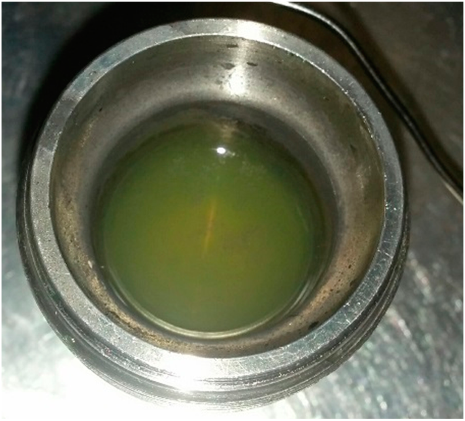
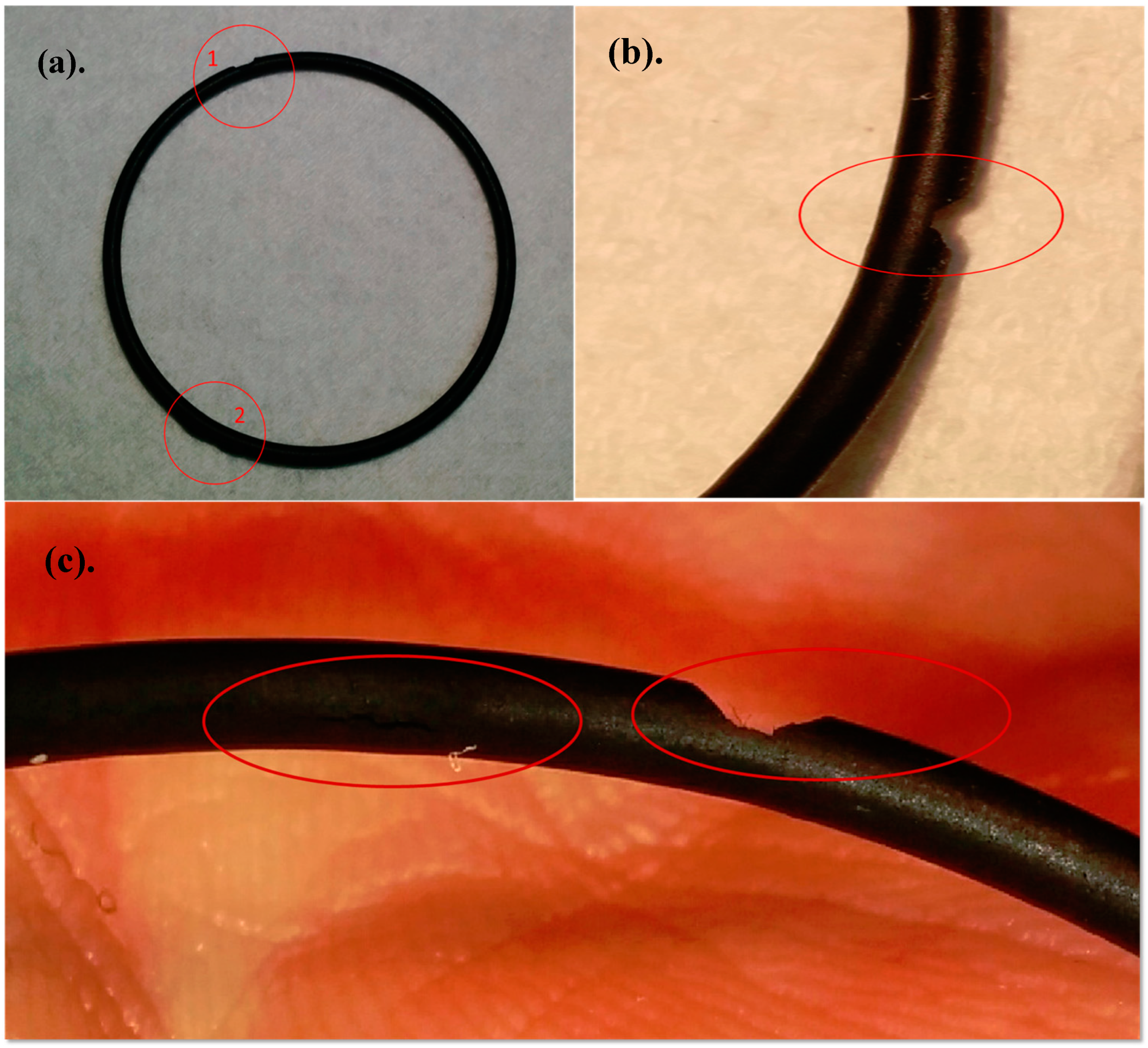
The autoclave was opened later in the day, where it was found that Kalrez O-ring had broken and the water–glycol circulating fluid used for temperature regulation of the experiment entered the autoclave cell (shown in
Figure 4). Upon close inspection of the damaged O-ring, some blistering was observed inside and outside as shown in
Figure 5.
The dimensions of the experimental bay, laboratory, and concentrations of H
2S released after the leak are presented in
Table 2. The concentrations of the H
2S concentration inside the experimental bay was calculated by expansion of the H
2S inside the autoclave into the volume of the bay. The concentration of H
2S was again calculated by expanding the H
2S into the volume of the building exhaust system. The concentration of H
2S released to the bay under dynamic flow was calculated to be ca. 250 ppm, which was well-contained inside the experimental bay as evidence by the wall detectors in the neighboring bays not reaching a low alarm condition (5 ppm). It is estimated that the H
2S was removed by the building ventilation system within a minute. Upon exit from the building ventilation system, ca. 51 ppbv H
2S was released to the environment, which posed minimal threat to the general public.
This is already a small-volume system intended to reduce the quantity of H2S in the experiment, and this is the first Kalrez seal to fail on these autoclaves in our laboratory. The seal was new when installed, not over-pressurized or overheated. The seal was ca. two months old and is likely to have blistered with the changing of pressure between experiments. During these changes, the system crossed the liquid–gas phase boundary for H2S, which could potentially cause some unexpected blistering. Due to this event, our laboratory procedures now call for replacing the seal every time there is a transition from liquid to vapor phase to avoid excess elastomer depressurization. We note that other elastomers are available, but do not contain the same temperature rating.
Examination of the SD card in the VA301C control panel post-incident revealed that the SD Card was corrupt, thus we were unable to obtain a time profile of the H
2S concentrations inside the work bay where the leak occurred. This SD card was replaced and data logging was reinstated. Thereafter, logged data was downloaded from the SD card to a computer on a quarterly basis to reduce the risk of recurrence. Temperature and pressure logs for the experimental system were not available; however, photographs of the logging system were taken ca. 25 min after the incident (
Figure 3). High-frequency logging between experiments also was recommended. The latter was not implemented previously because there were too many data for constant logging of the experimental systems. LabView programming is being updated with the appropriate expansion of memory.
4. Conclusions
We have discussed the risks associated with the exposure to H2S, preventive control measures and detection monitoring involved in processes handling or generating H2S. Using an incident in our laboratory as a case study, we reported an H2S leak as a result of a damaged perfluoroelastomer O-ring on an autoclave vessel that occurred during heating to dissociate the formed hydrate before depletion. The elastomer seal was two months old and had gone through several pressurization/depressurization cycles. While an abbreviated version of this event was previously reported within the University of Calgary’s Occupational Health and Safety Management System, data for H2S releases and seal failures in laboratories are rare; therefore, learnings from this near-miss event can be useful to other sour gas laboratories and researchers.
Both the administrative and engineering controls worked well and as they were designed to work, except for a failed SD card used to log H2S detectors. Additions to our previous procedures now include: (1) changing autoclave seals after the first exposure to a liquid-to-gas phase change, (2) quarterly download of SD card data logging to test the quality/integrity of the data, and (3) continuous logging of experimental systems between experiments. While the first change deals with avoiding a similar future failure, the latter two procedural changes allow for increased data and learning with any potential future event.

 ,
, 


