1. Introduction
Traffic and road safety is a serious concern worldwide, and multi-phased research has been undertaken in recent years. The United Nations General Assembly has made an important initiative to reduce the fatality rate in traffic accidents around the world by 50% and provided funds for research. In this context, Turkey has prepared a 10-year vision program covering traffic education and training, safety and enforcement, health and emergency assistance initiatives, and the improvement of traffic safety with engineering measures [
1,
2]. This program has been implemented by Ministries of Education, Interior, Health, and Transportation. Since 2010, serious steps have been taken regarding traffic safety in Turkey. These advances include speed control using smart detection systems, the enforcement of traffic rules through cameras, the reduction of arrival times of ambulances in an accident site, and providing traffic safety culture to students of all ages. These undertakings have resulted in a 10% decrease in fatal accidents in Turkey; however, according to statistical data, the level of achievement is not at the desired level of 15%. Lack of road restraint system utilization is one of the areas that needs to be improved [
1].
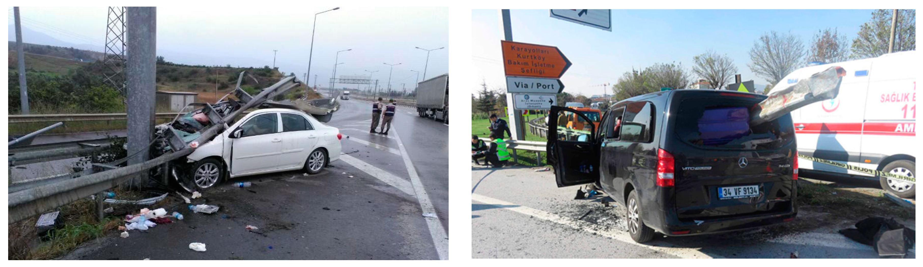
Crash cushions are widely used in developed countries to protect vehicles against impacts with fixed, sharp, narrow, and rigid objects located at road exit locations, tool booths, workzones, barrier ends, and trees [
3,
4]. As shown in
Figure 1, collision with unprotected objects increases the severity of accidents and results in fatalities. According to predictions by the Turkish statistics institute (TUIK), the number of fixed object accidents is on the rise, which creates concern for road-safety targets set by the Turkish Government [
5]. Crash cushions in general are designed to slow down and contain the impacting vehicle in a controlled way by absorbing its kinetic energy. The Istanbul Metropolitan Municipality (IMM), which is responsible for traffic safety within the city of Istanbul, expressed interest in utilizing low-cost and nationally developed crash cushions in Istanbul due to budget constraints [
1].
The aim of this project is, therefore, to develop a new hybrid crash cushion system, called the ulukur crash cushion (UCC), made out of linear, low-density polyethylene (LLDPE) containers and steel plates for the IMM. In this respect, the UCC will have low initial maintenance and repair costs with reusable parts. The crashworthiness of the system is evaluated both numerically and experimentally. The finite element model of the UCC is developed, and impact performance is analyzed using LS-DYNA in accordance with TSEN 1317 crash testing standard [
6,
7]. Following the simulations, full-scale crash tests were performed to validate the computer simulation results. Both the simulations and crash tests show acceptable agreement. Further crash tests are planned to fully evaluate the crashworthiness of the new crash cushion system.
2. Details of Ulukur Crash Cushion Developed
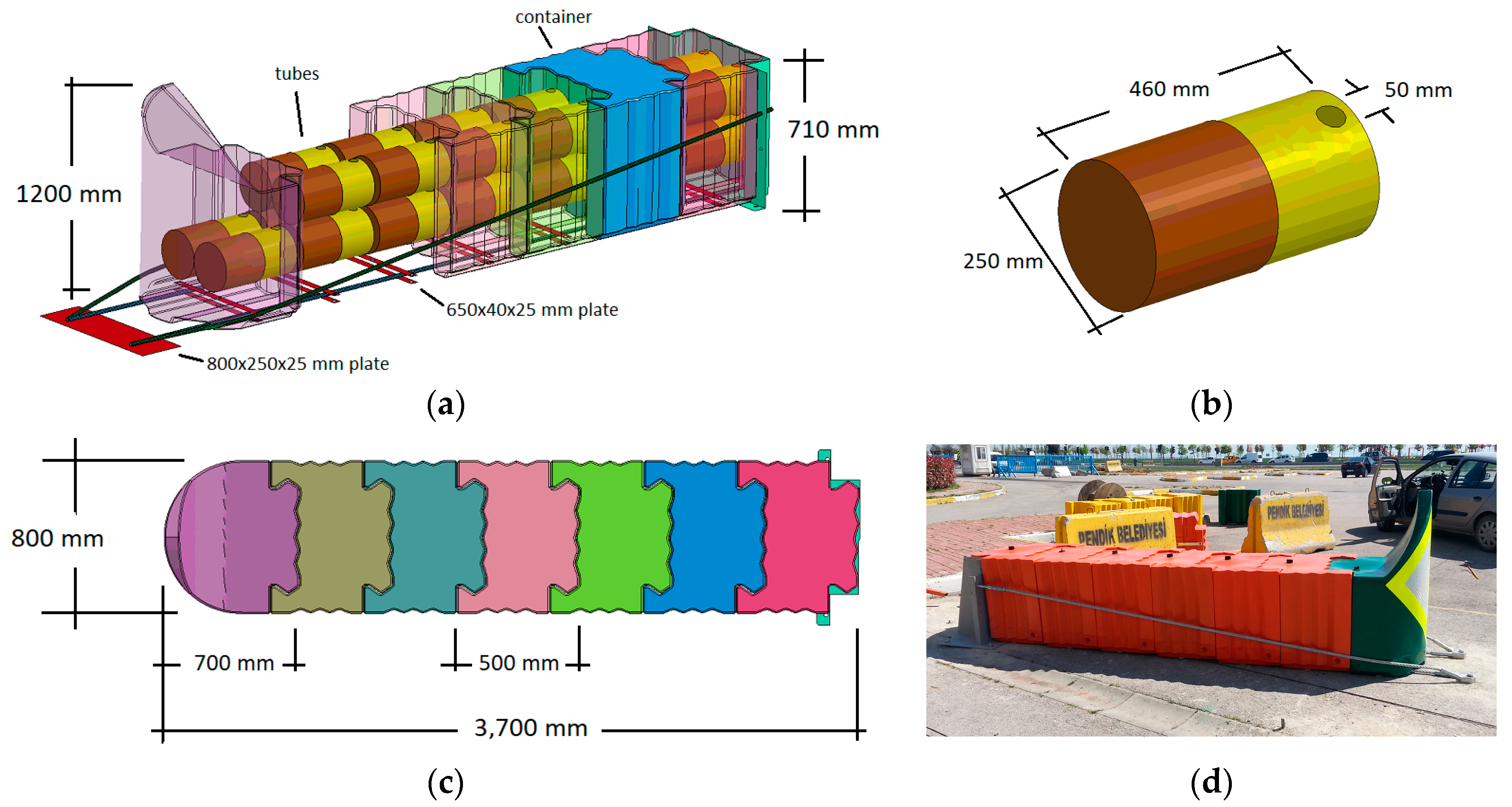
Ulukur crash cushion (UCC) design is composed of linear, low density polyethylene (LLDPE) containers, energy-absorbing tubes, steel cables, lower plates, and back support plate. Geometrical details of these materials are provided in
Figure 2. Containers are produced using LLDPE, since it is a dependable and cost-effective material that could sustain large deformations, endure dynamic forces, and absorb kinetic energy of the impacting vehicle without crack formation. Detailed technical information about LLDPE can be found in a study by Cozzi et al. [
8]. The measurements for the LLDPE containers are 500 mm long × 800 mm wide × 710 mm tall × 8 mm thick. In addition, 250 mm in diameter, 460 mm long energy-absorbing tubes made out of LLDPE are utilized inside the containers to improve the crash performance of the design. 50 mm in diameter holes are provided on tubes to allow controlled air release. The number of tubes varied based on the container type. In other words, as shown in
Figure 2, the lead container with a shield included two tubes, whereas all the other standard containers included four tubes. This is intended to provide a soft nose-section for vehicles with low-energy impacts. As the impact energy increases, so do the energy absorption capacities of the UCC design. Material properties of LLDPE are provided in
Table 1.
The UCC design developed in this study is composed of six containers and a frontal shield. The design is actually intended for 110 kph impacts, so the original design with six containers is not altered for 50 kph impact. Total length of the design is 3700 mm. The measurements of UCC elements are provided in
Figure 2. This design is intended to provide safe containment and redirection for 50 kph head-on and side impacts. Since UCC has a modular nature, the design could be easily converted to 80, 100, or 110 kph impacts by adding more containers, tubes, and steel members. Thus, the length of the system can change based on target design speed. As shown in
Figure 2, UCC used four 19 mm diameter steel cables (two on the bottom and two on the side), and cables are anchored to steel plates at both ends. Bottom cables run between two 650 mm wide × 40 mm wide × 25 mm thick steel plates located under the containers. This allowed controlled deformation of containers during frontal and side vehicle impacts. Two side cables are used to improve lateral stability of the UCC design.
3. TS EN 1317 Crash Testing Standard for Crash Cushion Evaluatıon
To assess the performance of crash cushions against vehicle impacts, Part 3 of EN 1317 standard, named “road-restraint systems—part 3: performance classes, impact test acceptance criteria and test methods for crash cushions” is followed [
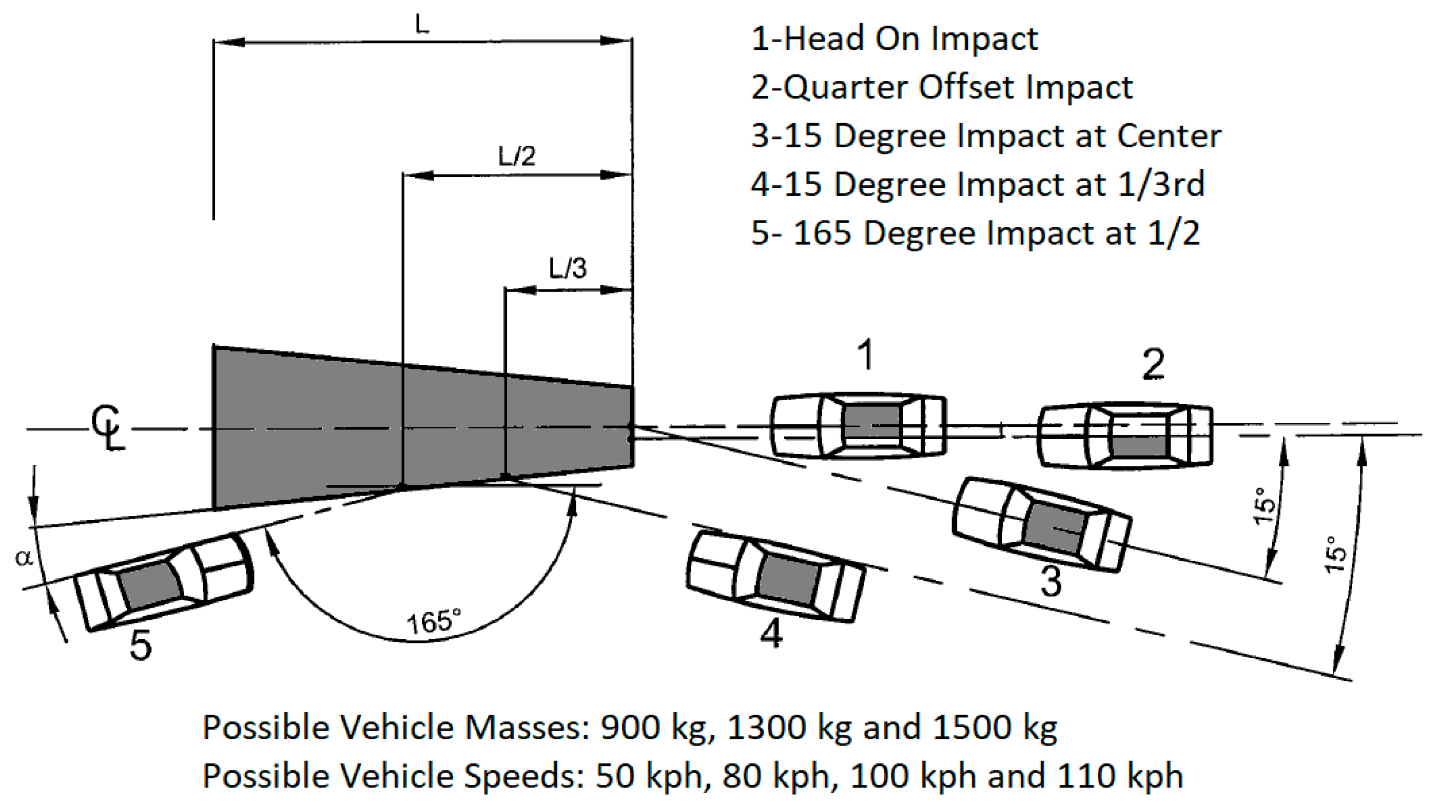
6]. According to this standard, vehicles weighing 900, 1300, or 1500 kg traveling at speeds of 50, 80, 100, or 110 impact crash cushions in five different approaches.
Figure 3 shows all possible test combinations described in EN 1317 standard Part 3 [
6]. As shown in
Table 2, for 50 kph tests there are only two tests, namely, TC 1.1.50 and TC 4.2.50; a 900 kg passenger car at impact position 1 and 1300 kg passenger car at impact positon 2, respectively, are specified. Both computer simulations and full-scale crash tests on UCC design are performed at 50 kph. In other words, impact performance of the UCC design is evaluated using TC 1.1.50 and TC 4.2.50 crash tests [
6].
4. Computer Simulation of UCC Design
Before pursuing costly, full-scale crash testing, a detailed finite element simulation study was performed on UCC design. A highly non-linear and large-deformation finite-element code LS-DYNA developed by the livermore software technology corporation (LSTC) was used to model the barrier and simulate the vehicle-barrier impact event [
7]. Details of the bridge rail and both vehicle models are explained below.
4.1. Finite Element Model of UCC Design
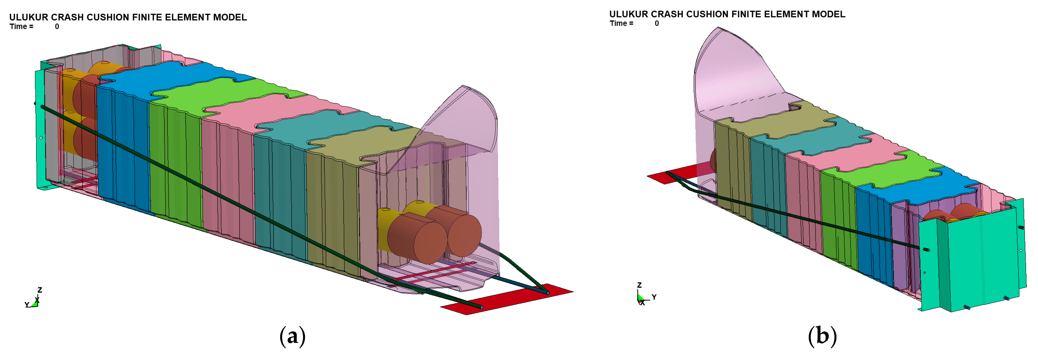
A finite element model of the UCC was developed to assess the crash test performance of the design. The model, as shown in
Figure 4, consisted of 143,063 nodes, 135,389 shell, and 4264 solid elements. Shell elements represented the LLDPE members and steel plates of the model, while solid elements represented the steel cables. The shell elements of the LLDPE containers and internal tubes that are expected to get in direct contact with vehicles and thus experience severe deformations are modeled with full integration formulation to accurately represent the complex interactions and behavior. All steel elements were modeled with default element formulation for computational efficiency.
Since containers are expected to sustain large plastic deformations and possible crushing, a piecewise linear plastic material definition was used to model the LLDPE elements [
11,
12]. Since no failure is expected in steel members, a rigid material modeling was used to represent plates and cables. Steel cables were firmly attached to steel plates at both ends, and steel plates were secured to ground using unfailing connections.
In an actual UCC installation, connections between the members, such as lower steel plates and containers, and steel plates to ground, are established using bolts and nuts. To accurately represent the behavior of these connections during full-scale crash testing, CONSTRAINED_SPOTWELD option in LS-DYNA was used [
7]. By definition, this option keeps members connected until a certain force criteria is met. Then, the connection fails and members can move freely. To determine the required force level that fails a connection, a detailed model is constructed using LS-DYNA. The behavior of the connection was examined under different loading conditions. A reasonable failure criterion obtained from the component simulation was used in the connection model [
11].
4.2. Vehicle Model
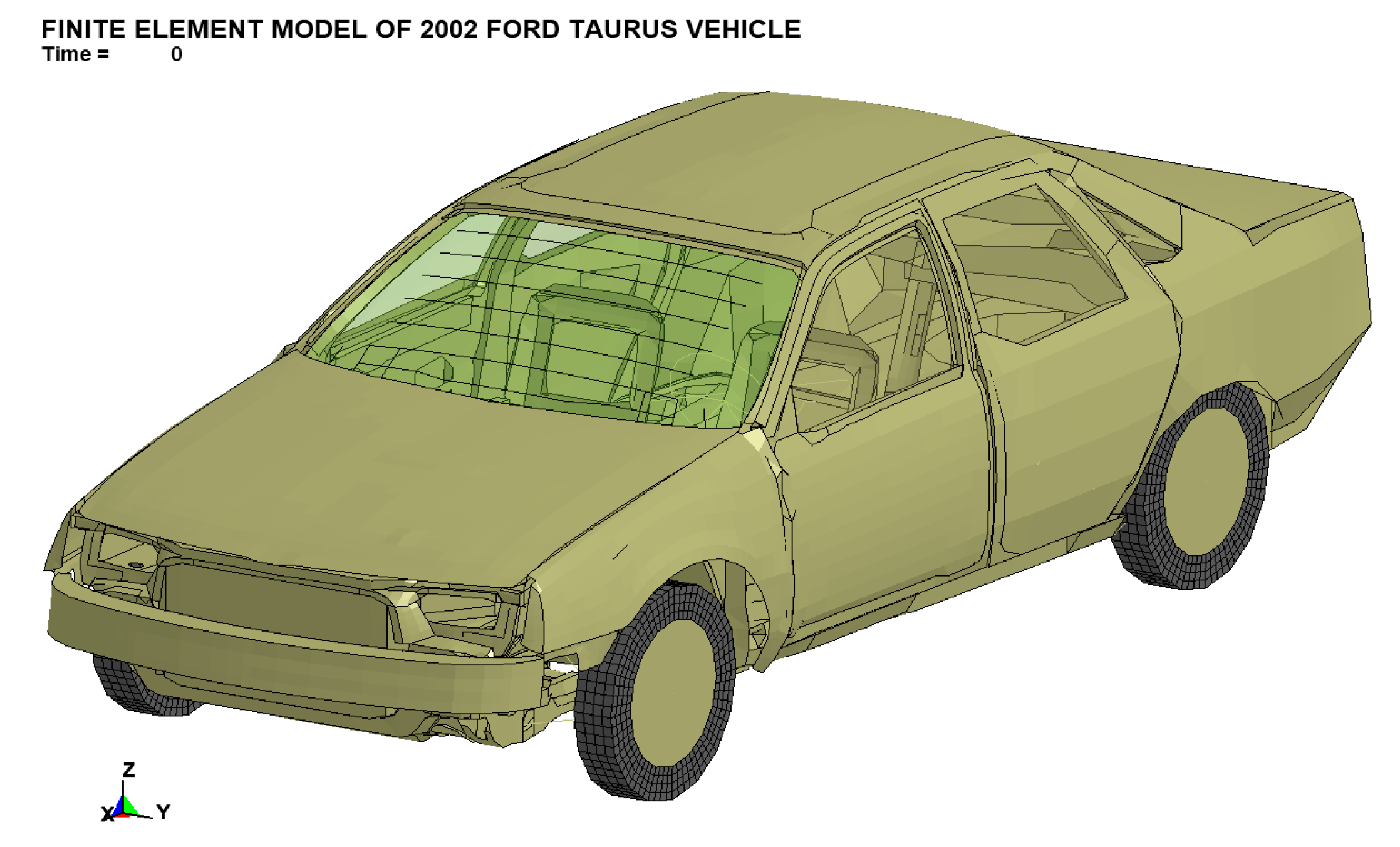
After the development of the UCC model, a small passenger car model was used to meet the EN 1317 standard requirements to impact the barrier. A 2002 Ford Taurus vehicle model obtained from the National Crash Analysis Center (NCAC) was used in the study [
13]. The mass of the empty vehicle was adjusted to 900 kg, and it could have been increased to 1300 kg by adding extra mass elements. This particular vehicle model was used in many previous studies with success [
14]. A picture of the vehicle is shown in
Figure 5.
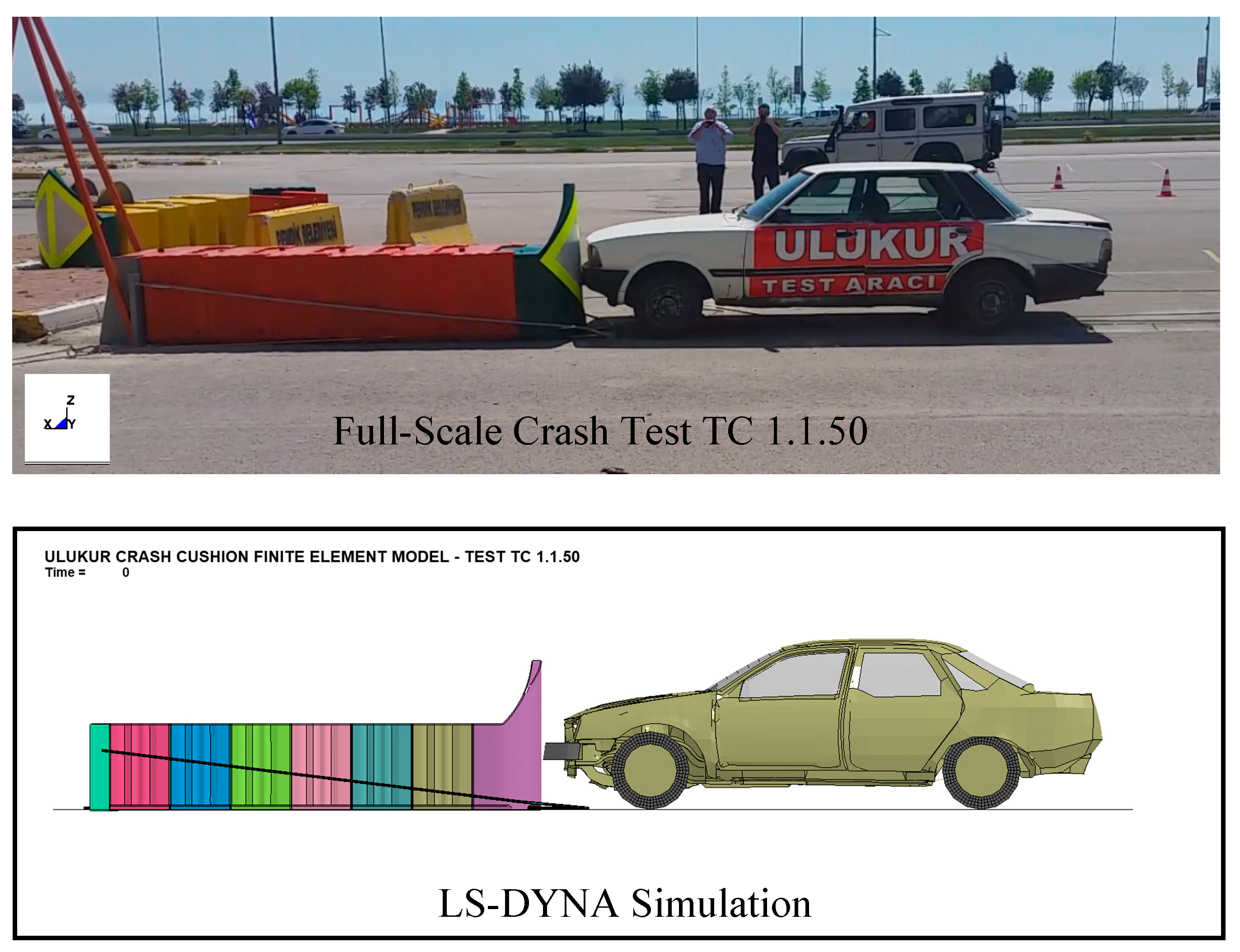
4.3. TC 1.1.50 Simulation
After the final modifications on the vehicle model, the simulation was setup according to TC 1.1.50 conditions specified in EN 1317 part 3 [
6]. This head-on crash test with 900 kg vehicle is performed to evaluate the energy-absorption capability of the UCC design and its effectiveness at reducing the velocity of impacting vehicle in a controlled manner, thus reducing occupant injury risks. As shown in
Figure 6, the vehicle was positioned in front of the cushion at 0 degrees impact angle. The vehicle speed was 50 kph. In this simulation no dummy was used. Simulation was run about 0.15 s until the vehicle’s kinetic energy completely dissipated by the crash cushion and vehicle was pushed backwards. As shown in
Figure 7, vehicle hit the barrier; instantly, the front container began to deform and bent towards the impacting vehicle. 0.06 s after the initial impact, the kinetic energy of the vehicle was significantly reduced and the velocity of the vehicle was approximately 28 km/h. 0.072 s after the initial contact, the second container began to deform and absorbed the rest of the kinetic energy of the vehicle. Thus, 0.12 s after the initial impact with the UCC, vehicle was brought to a controlled stop. Vehicle left the UCC in a stable and upright position. Energy absorption performance of the UCC was acceptable, which resulted in low occupant risk values that were measured inside the vehicle. A picture of the deformed shape of the barrier after TC 1.1.50 simulation is shown in
Figure 8. Based on the simulation predictions, it was determined that UCC design successfully contained and stopped 900 kg vehicle with minimal injury risk to occupants.
4.4. TC 4.2.50 Simulation
A second simulation study was also performed to evaluate side impact capacity of the UCC design. As described by test TC 4.2.50, a 1300 kg car model was positioned so that it would impact the cushion 1/3rd of the length (see
Figure 9). The vehicle contacted the barrier at 15 degrees angle, and the velocity of the vehicle just before the impact was 50 kph. Following the initial contact, as shown in
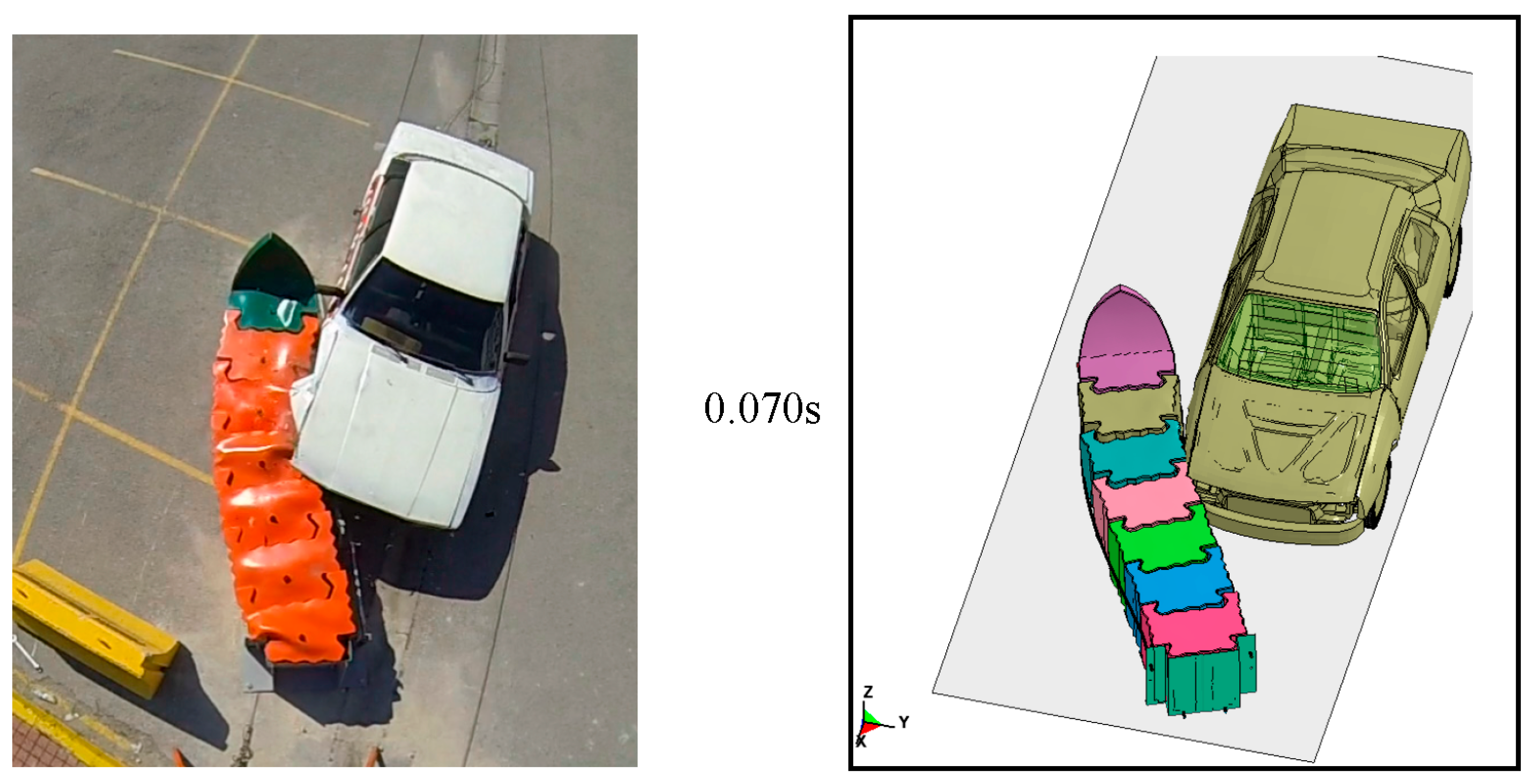
Figure 10, first and second containers began to deform laterally, thus absorbing the impact energy of the vehicle. As the vehicle continued to slide on the side of the UCC, it contacted more containers and vehicle speed was further reduced. At 0.1 s after the initial impact, the first four containers received moderate damage and vehicle’s velocity was almost 28 kph. As shown in sequential pictures in
Figure 10, 0.2 s after the initial impact, cushion was able to contain and redirect impacting vehicle without any breakage of the elements. Damage to the UCC and vehicle were moderate. The vehicle left the UCC in a stable and upright position. Energy absorption performance of the UCC was acceptable, which resulted in low occupant risk values measured inside the vehicle. A picture of the deformed shape of the barrier after TC 4.2.50 simulation is shown in
Figure 11. Based on the simulation predictions, it was determined that UCC design has the potential to satisfy 50 kph test requirements described at EN 1317 part 3.
5. Full-Scale Crash Testing
After performing two successful simulation studies for tests TC 1.1.50 and TC 4.2.50, same tests were performed using full scale crash cushion. Crash tests were run in Istanbul during the summer of 2016. These tests were intended to both verify the simulation findings and conclusively prove the acceptability of UCC design for 50 kph conditions.
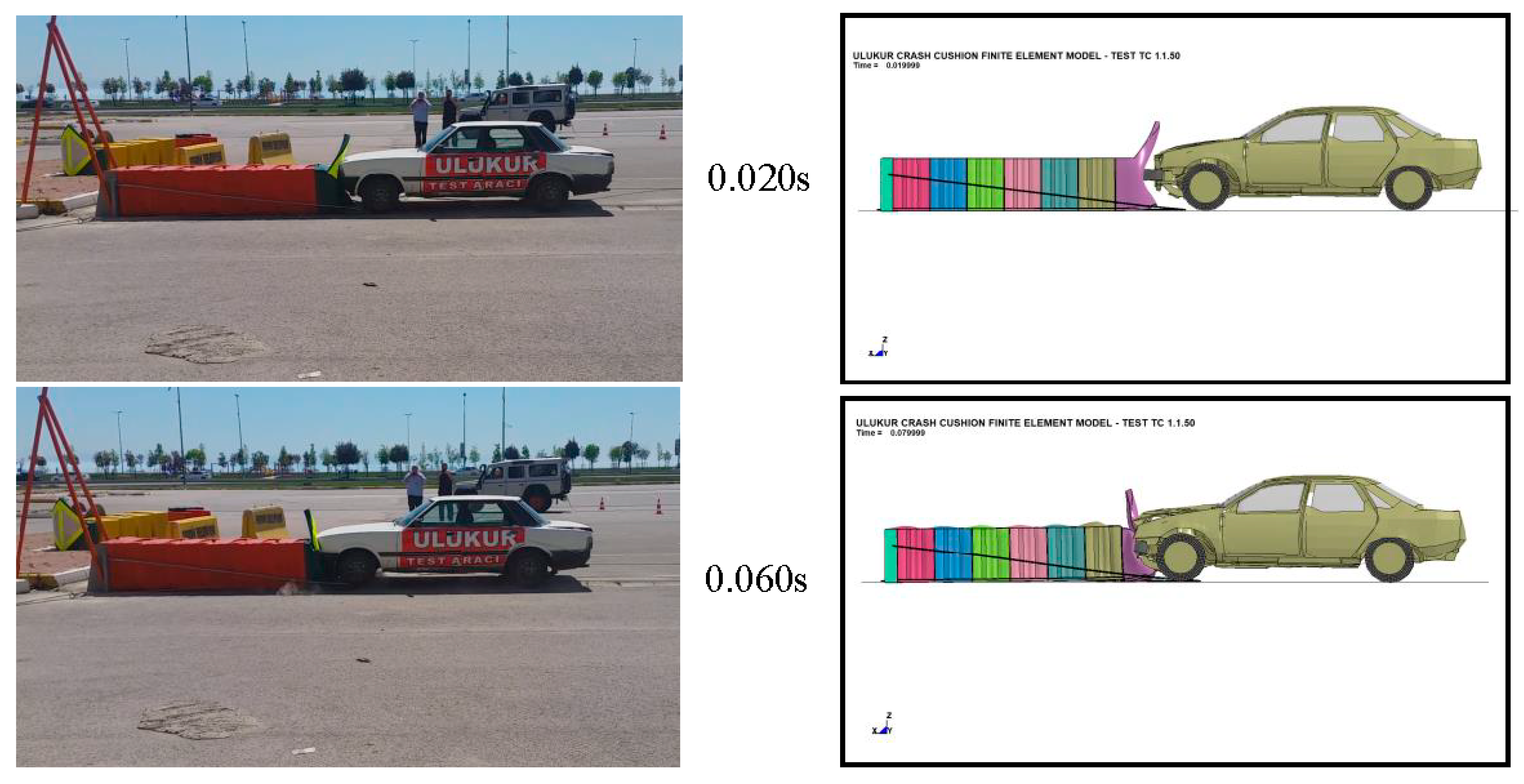
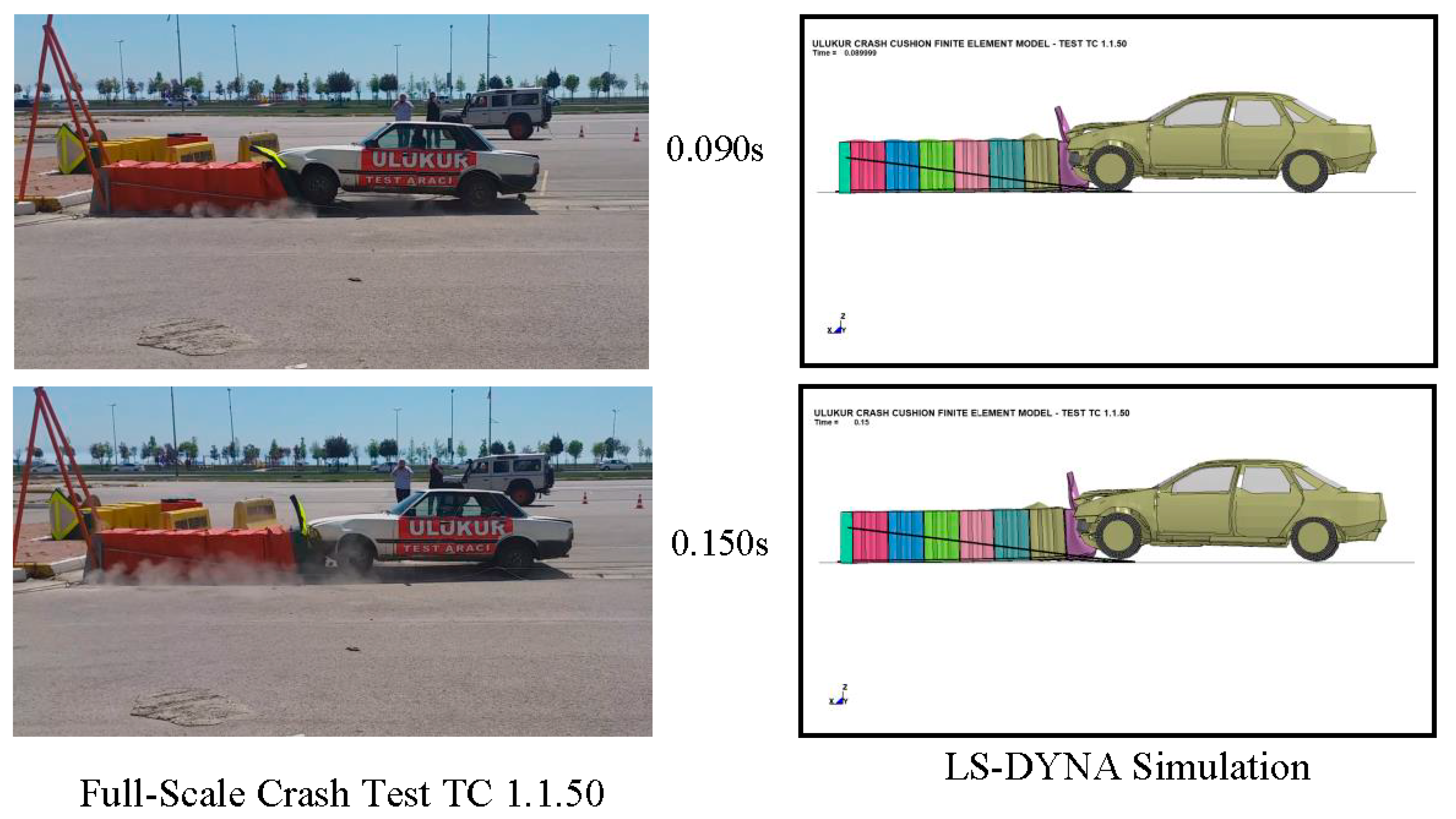
5.1. Crash Test TC 1.1.50
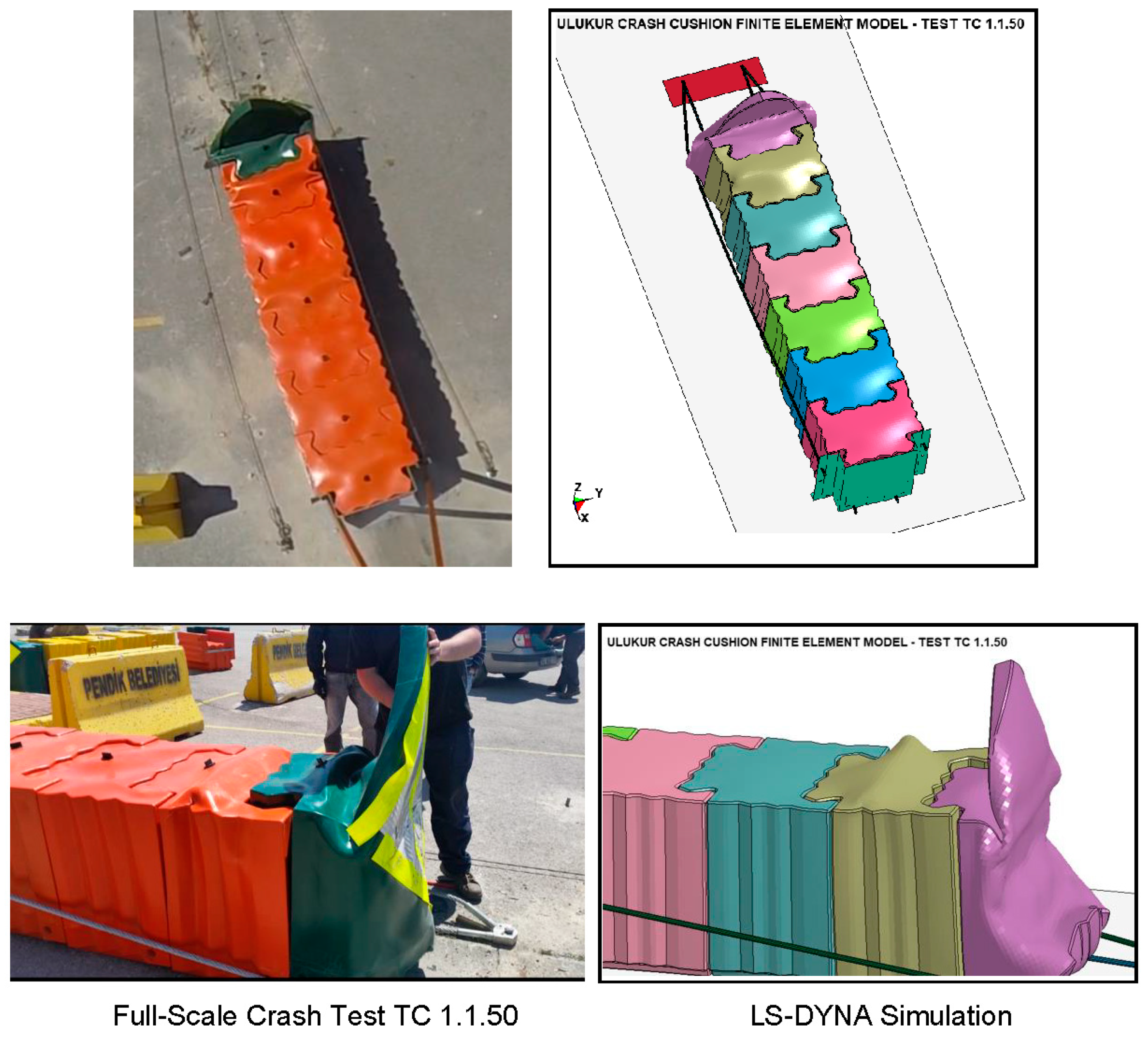
As shown in
Figure 6 and
Figure 7, a full-scale crash test was performed on UCC design according to EN 1317 part 3 TC 1.1.50 conditions [
9]. The UCC design was installed on concrete pavement and the impact point, as described in EN 1317 part 3, was a 1991 model Ford Taurus, which used as the test vehicle. The total mass of the tested vehicle was 900 kg when empty and 1300 kg with the addition of dummy and measurement devices. The vehicle positioned in the test track accelerated towards the test article at an angle of zero degrees using a cable pully mechanism and impacted the barrier at 51.5 kph. Behavior of the UCC and the vehicle are illustrated in
Figure 7. As expected, vehicle was not able to damage the cushion significantly. Only the first and second containers compressed and absorbed the kinetic energy of the vehicle. The vehicle slowed down in an acceptable manner and came to a stop. Data collected from the accelerometer, which was installed at the vehicle’s center of gravity, were used to calculate the occupant injury risks. Due to the softened nose design of the barrier and low speed of vehicle occupant injury risk, the values were determined to be negligible. Results of TC 1.1.50 crash test showed that the UCC design is soft enough to contain and stop an impacted vehicle in an acceptable manner.
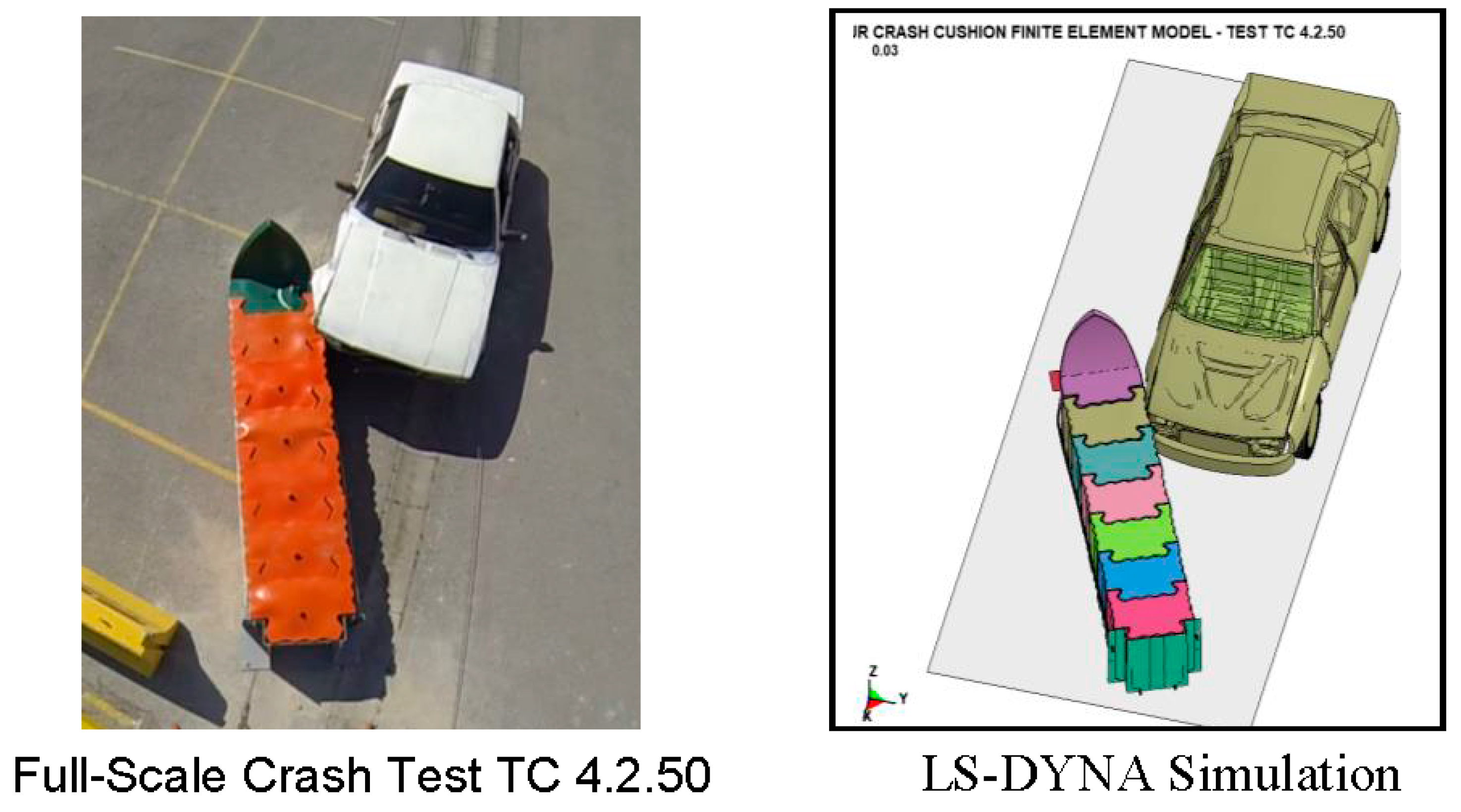
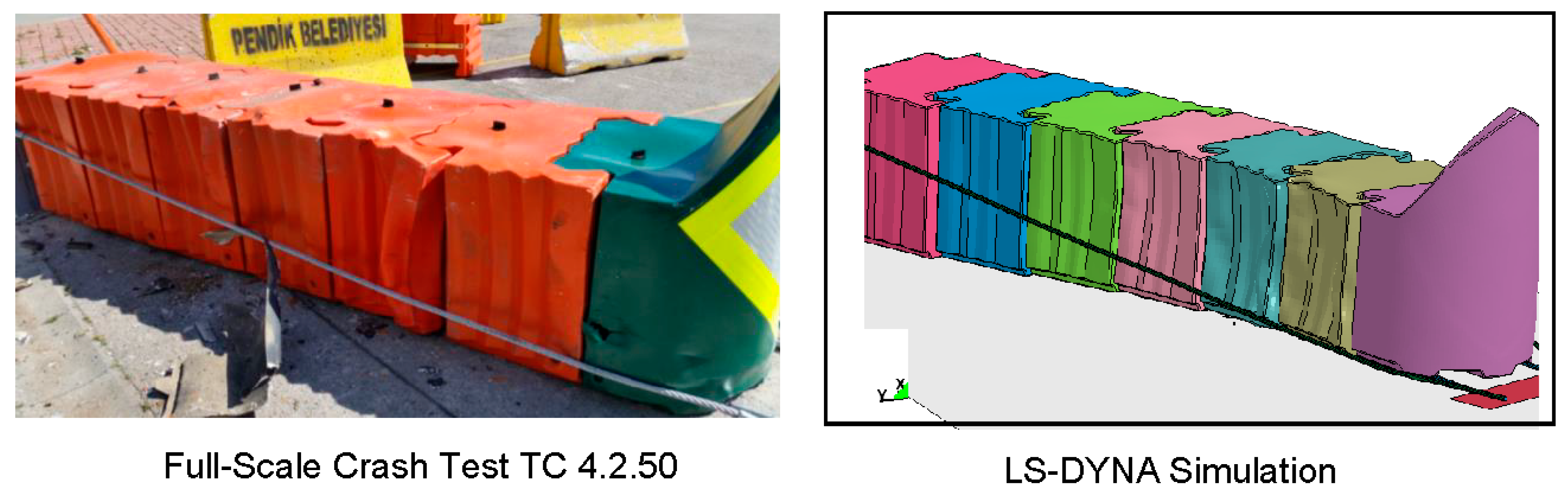
5.2. Crash Test TC 4.2.50
After repairing damaged containers and rotating the cushion 15 degrees, a second crash test was performed on UCC design according to EN 1317 part 3 test TC 4.2.50 conditions [
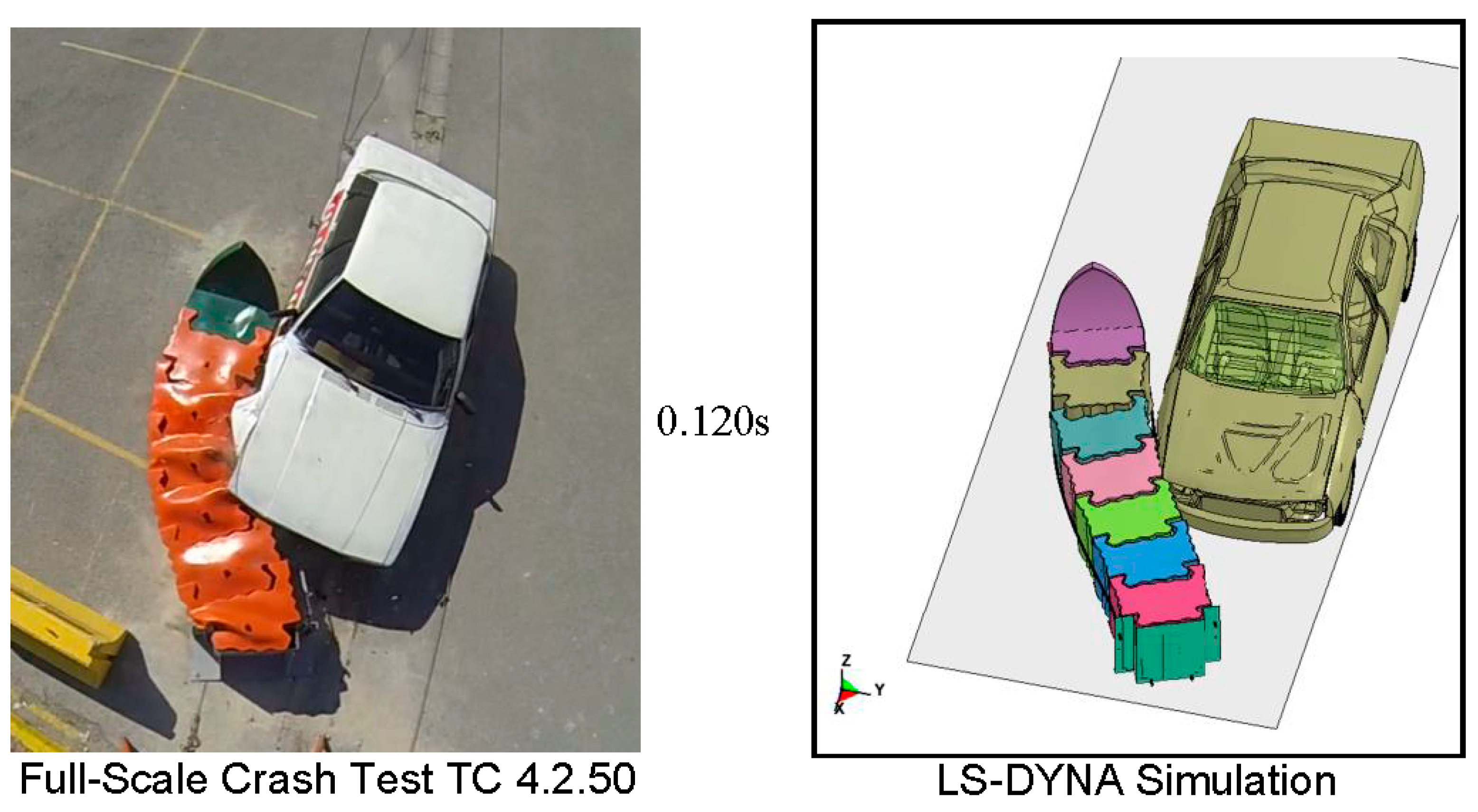
10]. As shown in
Figure 9, a 1320 kg Ford Taurus impacted the barrier with a speed of 51 kph and at an angle of 15 degrees. The impact point was 1.5 m away from the nose, which is equal to one third of the distance of the UCC. Following the initial contact, as shown in
Figure 10, first two containers that received the impact force began to deform and absorb the initial impact loads. As the vehicle continued to slide on the side of the UCC, as in the simulation study, it contacted barriers number three and four, which reduced the vehicle speed a further 0.1 s; after the initial impact, the first four containers received moderate damage and the vehicle’s velocity was almost 32 kph. As shown in sequential pictures in
Figure 10, 0.22 s after the initial impact, cushion was able to contain and redirect the impacting vehicle in an acceptable manner. Damage to the UCC and vehicle were moderate. The vehicle left the UCC in a stable and upright position. Energy absorption performance of the UCC was acceptable, which resulted in low occupant risk values measured inside the vehicle. A picture of the deformed shape of the barrier after TC 4.2.50 crash test is shown in
Figure 11. As predicted by LS-DYNA simulation study, UCC design successfully passed the 50 kph test requirements described in EN 1317 part 3 [
6].
6. Summary and Conclusions
This paper deals with designing, analyzing, and testing a new, reusable, low-cost, and simple crash cushion, UCC, for roads with 50 kph speed limits. UCC design included LLDPE containers with embedded LLDPE energy-absorbing tubes as dampers. The design was strengthened by steel cables and steel plates. The crashworthiness of the system was evaluated both numerically and experimentally. Finite element analysis of the UCC design showed that the design is flexible enough to contain, and successfully stop, a 900 kg car impacting head-on and rigid enough to successfully redirect the 15 degree side impact of a 1300 kg vehicle at one third of the location of the design. Following the promising simulation study, the design was installed at a test facility and two full scale crash tests were performed on UCC to conclusively determine its performance under 50 kph vehicle impacts. Both simulation and crash test results agreed well, proving the crashworthiness and acceptability of the design at 50 kph. Damage to UCC was moderate, and the occupant risk factors were below injury threshold. Since UCC design is composed of modular elements, the design could be easily repaired and put back to service. Finally, performing further crash tests at higher speeds, such as 80, 100, and 110 kph, is recommended to fully assess the acceptability of the new crash cushion system developed.


