1. Introduction
Frequency-selective and tunable detection of terahertz (THz) frequency signals is an operation that is important for many different applications—from medical scanning, to security, to high-speed 6G communication and radio astronomy [
1]. Due to the rarity of resonators with natural frequencies in the THz (from 0.1 to 10 THz) frequency range, the tunable resonance detection in this frequency range is still a significant challenge [
2,
3,
4,
5]. One option to realize resonance detection of THz-frequency signals is to use antiferromagnetic (AFM) crystals that naturally have frequencies of the antiferromagnetic resonance (AFMR) in the THz-frequency range. These high frequencies of the AFMR are related to the existence of a strong exchange interaction between the AFM magnetic sublattices (internal exchange magnetic fields of up to
–
T) [
6].
It has been shown theoretically that AFMs can be used as active layers of THz-frequency oscillators [
7,
8,
9,
10] and detectors [
11,
12,
13]. Recent experiments on the effect of spin-pumping performed in both uniaxial [
14,
15,
16] and biaxial [
17,
18] AFMs indicate the possibility of development of THz frequency-detectors based on antiferromagnet/heavy metal (AFM/HM) heterostructures. In this work, we analyze the available theoretical and experimental data on the properties of AFM crystals, and describe the influence of the AFM crystal anisotropy, magnitude and orientation of the external bias magnetic field, as well as the polarization of the received THz-frequency electromagnetic signal, on the possibility of resonance detection of such signals using spin pumping in passive spintronic detectors-based AFM/HM bilayers.
The general theory of spin-pumping and spin-transfer torque in AFM/HM layered structures was developed in [
19]. The influence of the signal polarization and the type of the AFM anisotropy on the detection of THz-frequency signals by the AFM/HM spintronic detectors has been further studied theoretically in [
11,
13]. It was found that a
uniaxial AFM gives a zero rectified voltage for a
linearly polarized AC spin current signal, but can detect a
circularly polarized AC signal [
13]. It was also found that a
biaxial dielectric AFM (such as NiO) can be used as a sensitive element of a resonance quadratic rectifier of
linearly polarized AC spin current signals, and that a sensitivity of such a rectifier could be in the range of 1 kV/W [
11,
13]. The conditions necessary for using
uniaxial AFMs for the detection of
linearly polarized signals have not been studied in detail, so far.
It is well-known (see, e.g., [
6]) that, in the absence of an external bias magnetic field, the AFMR frequencies in AFM crystals are proportional to the square root of the product of the anisotropy fields and the AFM internal exchange field. The AFM internal exchange magnetic field, which keeps the AFM sublattices anti-parallel to each other, reaches hundreds of Tesla, while the AFM anisotropy field is much smaller (from
T to several T), and, therefore, the tuning of the AFMR frequency is, usually, done by changing the AFM anisotropy fields. The variation of the anisotropy fields can be done using magnetostriction in the adjacent piezoelectric layer [
20,
21], driving DC current through the adjacent HM layer [
13], or by changing temperature [
22]. When an external bias magnetic field is applied to a uniaxial AFM, its influence on the AFMR frequency depends on the field direction relative to the anisotropy easy axis, and linear tuning of the AFMR frequency is possible when the bias field is parallel to the anisotropy easy axis, but the bias field magnitude necessary for the AFMR tuning is rather large, of the order of several tesla.
In this work, we consider a theory of resonance detection of both
linearly and
circularly polarized electromagnetic (EM) signals via a spin-pumping mechanism in AFM/HM heterostructures. We assume the presence of a DC external bias magnetic field that can be used for tuning the AFMR frequency of the detector, as it was done in recent AFM spin-pumping experiments [
14,
15,
16]. We also study the additional influence of the bias magnetic field on the detector properties. The paper is organized as follows. In
Section 2, we describe the possible physical structure of an AFM/HM based detector. In
Section 3, we present a mathematical model of the magnetization dynamics in an AFM using the so-called “sigma-model” developed in [
23,
24,
25] for both uniaxial and biaxial AFM crystals. The expressions for the AFM-based detector sensitivity are presented in
Section 4, while the conclusions are given in
Section 5.
2. Physical Structure
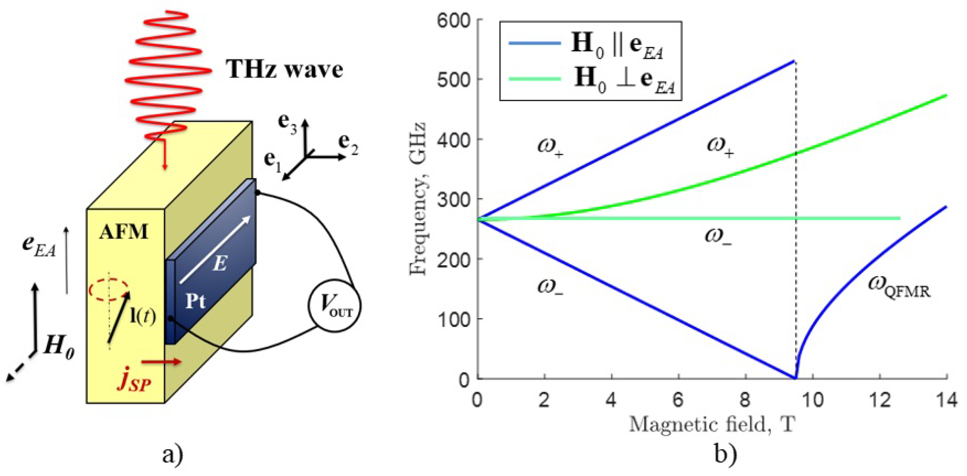
Let us consider a concept of a THz-frequency detector based on AFM/HM bilayer, which is shown in
Figure 1a. Here, the anisotropy easy-axis is oriented in the plane of the sample
. The magnetic field component of the AC electromagnetic field
created by an external signal is oriented in the plane perpendicular to the easy-axis
, where
and
for the cases of linear (LP) and circular (CP) polarization, respectively, while
and
are the amplitude and frequency of the AC magnetic field.
The external AC magnetic field induces torque, which acts on the magnetic sublattices of the AFM, and causes oscillations of the Néel vector
near the easy-axis, and creates a spin-current due to the spin-pumping mechanism [
6]:
where
is the real part of the spin-mixing conductance,
ℏ is the reduced Planck constant,
are magnetization vectors of the AFM sublattices, and
is the saturation magnetization of the sublattices. This spin current is then injected into the HM, which produces a charge current and electric field between the output electrodes
E through the inverse spin Hall effect (ISHE), and results in an electric DC voltage
. The experimental ISHE voltages and other physical parameters of different uniaxial and biaxial AFMs for the zero external DC magnetic field are presented in
Table 1, and they are all above tens of nV. One can see from
Table 1 the resonance frequencies of the presented AFMs lie in the THz frequency range. We use MnF
and NiO for our numerical simulations for uniaxial and biaxial cases, respectively, as materials with low damping at room temperatures, which give the acceptable quality factor for AFM resonance.
3. Magnetization Precession Induced by a Polarized THz EM Signal
A general phenomenological method for the description of the AFM dynamics is based on the use of coupled Landau–Lifshitz equations for the magnetizations of the sublattices
[
6]. Using this approach under the condition that the total magnetization
is small, I.V. Baryakhtar and B.A. Ivanov [
23] obtained an effectively closed equation describing the dynamics of an antiferromagnet in terms of a normalized (unit) vector
. In their derivation, it was assumed that the magnetization vector M of an antiferromagnet is a “slave” variable, and is determined by the vector
and its time derivative
. The dynamic equations of motion for the unit vector
are usually called the equations of the “sigma-model”, and their application greatly simplifies the analysis of both linear and nonlinear dynamic effects in antiferromagnets [
6]. A.F. Andreev and V.I. Marchenko [
25], as well as A.K. Zvezdin [
24], obtained the sigma-model equation based on the analysis of the dynamic symmetry of the AFM. In this section, we describe the magnetization dynamics in an AFM crystal using the sigma-model in the following form [
23,
25]:
where
is the spectral linewidth of the AFM resonance at zero bias magnetic field
[
13],
is the effective damping including Gilbert constant and spin-pumping term [
11],
is the gyromagnetic ratio. The vector product
is the gyroscopic torque [
25] and
is the magnetic energy density in the presence of the DC bias magnetic field, which can be expressed in the form (see for more details [
23,
25]:
Here characteristic frequencies are defined as follows:
,
,
, and
is the AFM internal exchange magnetic field,
are the AFM anisotropy fields corresponding to the easy and hard axes, respectively (see
Table 1). Some authors use a definition of the exchange field in an AFM,
, which is half of the exchange field
used in our current work. We use the definition
. following the classical papers on the magnetization dynamics in AFM crystals [
23,
25]. Thus, the left-hand side part in Equation (
2) contains the inertial, damping, gyroscopic, and anisotropy terms, respectively, while the right-hand side part of the equation describes the influence of the AC magnetic field of the external signal. Note, that in [
11,
13] an AC spin current with a torque
in the right-hand side of Equation (
2) was used as an excitation mechanism, where
is the density of the spin-current. Our further results on the study of model (2) with external electromagnetic radiation are also applicable to the case of a spin current.
Let us now consider the small-amplitude dynamics of the Néel vector expressed as a sum of the static component
, describing the AFM ground state, and a small dynamic vector
excited by the AC magnetic field of the external signal:
Note, that the vectors
and
satisfy the orthogonality constraint, i.e.,
. The ansatz (4) uses the assumption of a small change in the dynamic vector
near the stationary vector
, which describes the AFM ground state. This is a common technique in the theory of oscillations and waves. In such a linear theory it is assumed that the vector
is small, and we can linearize the original nonlinear sigma-model equation to obtain a linear dynamic equation for the vector
. In a nonlinear case, the ansatz
can also be used, but, then, Equation (
6) must be modified, and the nonlinear terms must be considered in that equation. Such nonlinear dynamics can include the second harmonic generation [
30], or the appearance of the self-oscillations [
8], but the theory of such nonlinear processes is beyond the scope of our current manuscript.
The equation defining the AFM ground state Néel vector
can be easily found from (3) as follows:
where
, and
is the unit vector along the DC bias magnetic field. Solving Equation (
5) gives the ground state Néel vector
.
Using Equation (
4) in Equation (
2) we can derive the following differential equation describing the oscillations of the dynamic part of the Néel vector
:
where matrices
,
,
can be expressed as follows:
Linear vectorial Equation (
6) describes the small-amplitude dynamics of the AFM Néel vector. The formal solution
of Equation (
6) for a harmonic driving signal
(here
) has the following form:
where
is the matrix
We can rewrite expression (9) in the form:
where
for LP and
,
for CP, and
Now, we can find a general expression for the AFM eigenfrequencies
in the case of zero effective damping
. These eigenfrequencies are found from the condition of the vanishing of the determinant of the matrix (10) in the following form (here we take
):
Let us consider several particular cases for the orientation of the external bias magnetic field relative to the axes in the uniaxial and biaxial AFM crystals.
For the case of a zero DC bias magnetic field, two eigenfrequencies
are degenerate, and equal to
. The dynamic vector
has, in this case, the simplest form:
This is a standard expression for the amplitude–frequency characteristic of an oscillatory system with one degree of freedom FM modes are (two AFM modes are degenerate and uncoupled).
In the case when
, the resonance frequencies from (13) can be found in the following form:
and
where
is the spin-flop field, at which the Néel vector changes its direction from the parallel to the external bias magnetic field to the perpendicular to it. The dependences of the resonant frequencies defined by the expressions (15) and (16) are shown in
Figure 1b. Such dependences were obtained experimentally for different easy-axis AFMs (see, e.g., [
15,
16]). Since the rectification of the modes having “quasi-ferromagnetic” frequency requires a bias field higher than the field of a spin-flop transition (which for MnF
is 9.4 T, and for
is 6 T), and, therefore, requires the use of sources of rather large magnetic fields, in the following we shall restrict our attention to the rectification of signals in bias fields below the spin-flop transition.
In the case when
, the AFMR frequencies are:
The upper frequency quadratically increases with the increase of the DC bias magnetic field, while the lower mode frequency is constant and equal to .
For the zero DC bias magnetic field two AFM frequencies
are non-degenerate and equal to
and
. Most often, the hard-axis field
is much larger than the easy-axis field
(see
Table 1 for the nickel oxide), and the effect of the easy-plane anisotropy variation on the higher resonance frequency can be neglected. Qualitatively, the nature of the dependences shown in
Figure 1b coincides for the easy-axis and the easy-plane cases.
In the particular case when
and
the resonance frequencies are equal to (before the spin-flop field [
29]):
For the one of the AFMR frequencies does not depend on the magnetic field, and the second one grows quadratically.
Let us now study the influence of the driving AC signal polarization on the rectified DC voltage in AFM obtained as a result of the spin pumping for various relative orientations between the direction of the external bias DC magnetic field and the anisotropy axes.
4. Rectification of THz-Frequency Electromagnetic Signals
Let us derive an expression for the inverse spin Hall DC voltage
induced by the spin pumping from the AFM into the adjacent HM layer. Using (1) and (4) we get this expression in the following form:
where
is the proportionality coefficient
L is the distance between output electrodes,
is the spin-Hall angle,
e is the electron charge,
is the spin-diffusion length, while
and
are the electrical resistivity and thickness of the Pt layer, respectively. For the input AC power of the EM signal
, where
c is the speed of light,
is the magnetic permeability,
S is the AFM layer cross-section, one can find the detector sensitivity defined as:
For the cases of linear and circular polarizations of the driving AC signal we get the detector sensitivities as:
where
.
Now, let us analyze the above obtained expressions (22) and (23) for detector sensitivity in two different cases of uniaxial and biaxial AFM crystals.
The rectified output DC voltage is equal to zero due to the fact, that the modes
are uncoupled for the LP in both cases
and
. When
, two modes
are mutually coupled due to the gyroscopic terms in Equation (
2), and a non-zero sensitivity can be obtained from (22):
One can see from the expression (24) that the detector sensitivity is proportional to the bias DC magnetic field
.
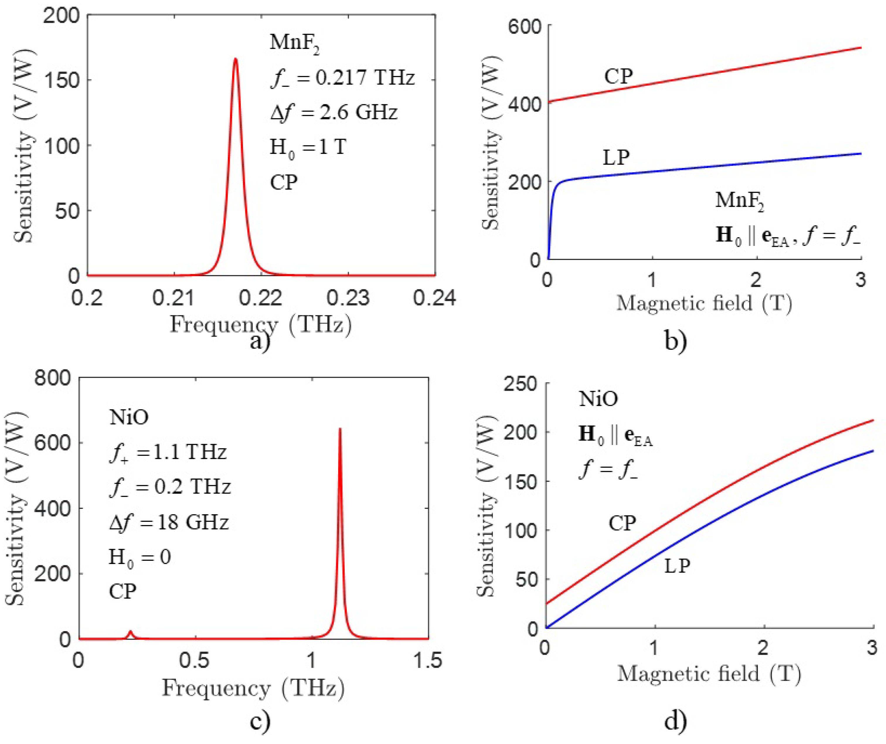
Figure 2a shows the resonance-type dependence of the sensitivity on the frequency
for the upper branch
of the resonance curve shown in
Figure 1a in the case of a non-zero external DC bias magnetic field. In our numerical calculations, we assumed that the AFM layer is made of MnF
, and used the following coefficients taken from [
16]:
,
,
,
,
,
m
,
,
. As can be seen from
Figure 2a and Equation (
18), the resonance sensitivity increases with the increase of the the bias magnetic field
. Note, that the input AC power of the EM signal is defined as
, so for the AC signal amplitude
and the AFM cross-section
we get the value of
. The dependence of the detector sensitivity on the bias magnetic field for linearly polarized (LP) and circularly polarized (CP) signals is shown in
Figure 2b for the above given parameters and nano-scale sizes of the AFM/HM heterostructure. When the magnitude of the DC magnetic field is varied, the resonance frequency shifts, as it is shown in
Figure 1b, while the spectral linewidth of a resonance curve remains unchanged, as it is equal to
. In the recent experiment [
15,
16] performed in bulk mm-size AFM samples the observed detector sensitivity was near
V/W, which is quite small compared to our above presented theoretical estimation made for a nano-sized AFM sample. We believe that the main reason for this huge difference is the relatively large size of the AFM layer used in [
15,
16]. It has been also theoretically demonstrated recently [
11,
13] that the sensitivity of an AFM detector can reach several kV/W for detectors using nanometer-thick AFM layers. As follows from expressions (19) and (20), the output voltage of an AFM detector is inversely proportional to the AFM thickness. As it was shown in [
11], when the AFM thickness decreases, there is an optimal AFM thickness at which the sensitivity reaches the maximum value. With a further decrease of the AFM thickness, the sensitivity decreases. To correctly calculate the sensitivity at thicknesses of the order of several nanometers, it is necessary to use the modified sigma model (2), in which the additional spatial derivatives are included. This calculation was presented in [
11], and it is not repeated in our current work. Thus, we come to the obvious conclusion that the nano-sized sensitive AFM elements should be used in the future design of the spintronic AFM detectors of THz-frequency EM signals. Another possible way to increase the detector sensitivity is to use several nano-scale detectors mutually coupled through a common HM layer, or to use magnetic tunnel junctions to extract the output voltage [
10].
For a circularly polarized EM signal in both cases
and
, one can get a non-zero diode sensitivity described by the equation:
The rectification of a THz signal at a zero bias magnetic field was studied earlier in [
13], where the driving THz-frequency signal had the form of a spin-polarized current. However, the presence of an external bias DC magnetic field removes the degeneracy of the eigen-frequencies of the system, and increases the magnitude of the rectified voltage. Additionally, the use of a driving signal with circular polarization makes possible the observation of the rectified spin-pumping voltage both in the presence, and in the absence of an external bias magnetic field. In contrast, in the case of a linear polarization of the driving signal, such an observation is realized only for
. As can be seen from
Figure 2, the sensitivity for CP signals is larger than for the LP signals at the same value of the DC magnetic field. In the CP case, the expression (25) consists of two terms: one is linearly proportional to the DC magnetic field, while the other one is independent of it. In contrast, in the LP case the sensitivity expression (24) contains only one term proportional to the DC magnetic field. The summary for the calculation of eigen-frequencies
and sensitivity at different ratios between the orientation of the external magnetic field is presented in
Table 2.
It was shown previously [
11] that a biaxial AFM can be used to rectify a
linearly polarized AC spin current in the case when the AFM easy plane is oriented
perpendicular to the plane of the AFM sample. The maximum value of the rectified voltage is achieved when the angle between the direction of the spin-current polarization and the directions of the AFM anisotropy axes is 45 degrees. In this case, it is possible to obtain a non-zero rectified voltage even in a
zero bias DC magnetic field.
At the same time, from the technological point of view, it is easier to fabricate biaxial AFM crystal in the case when the easy plane coincides with the plane of the sample, or is inclined to the sample plane at a small angle. In this work, we consider only the situation when the AFM easy plane coincides with the plane of the AFM sample.
For the determination of sensitivity in the case of a biaxial AFM one needs to use the general expressions (22) and (23). The analysis presented above for the uniaxial non-degenerate case is applicable to the biaxial case as well. The resonance curve for the NiO is shown in
Figure 2c, and is characterized by two resonance eigen-frequencies even in a zero DC magnetic field. The dependence of the diode sensitivity on the bias magnetic field obtained in such a case is shown in
Figure 2d. The sensitivity of the lowest-frequency mode in a zero bias magnetic field and at a linear polarization of the external AC signal is much smaller than for the case of a circular polarization (0.1 V/W for LP and 27 V/W for CP), but it is, in general, non-zero. In our numerical calculations we used the physical parameters for the NiO crystal taken from [
28]. It is easy to see that in the case of a biaxial AFM (similar to the above discussed case of a uniaxial AFM), the increase of the DC bias magnetic field leads to the increase of the diode sensitivity.


 ,
, 

