Article

Deposition of Crystalline GdIG Samples Using Metal Organic Decomposition Method

1
Department of Physics, Korean Advanced Institute of Science and Technology, Daejeon 34141, Korea
2
Department of Materials Science and Engineering, Chungnam National University, Daejeon 34148, Korea
3
Department of Materials Science and Engineering, Ulsan National Institute of Science and Technology, Ulsan 44919, Korea
4
Division of Scientific Instrumentation, Korean Basic Science Institute, Daejeon 34126, Korea
*
Authors to whom correspondence should be addressed.
These authors contributed equally to this work.
Magnetochemistry 2022, 8(3), 28; https://doi.org/10.3390/magnetochemistry8030028
Submission received: 31 December 2021 / Revised: 21 February 2022 / Accepted: 22 February 2022 / Published: 27 February 2022
(This article belongs to the Special Issue Advances in Antiferromagnetic Spintronics)

Abstract

:
Fabrication of high quality ferrimagnetic insulators is an essential step for ultrafast magnonics, which utilizes antiferromagnetic exchange of the ferrimagnetic materials. In this work, we deposit high-quality GdIG thin films on a (111)-oriented GGG substrate using the Metal Organic Decomposition (MOD) method, a simple and high throughput method for depositing thin film materials. We postannealed samples at various temperatures and examined the effect on structural properties such as crystallinity and surface morphology. We found a transition in the growth mode that radically changes the morphology of the film as a function of annealing temperature and obtained an optimal annealing temperature for a uniform thin film with high crystallinity. Optimized GdIG has a high potential for spin wave applications with a low damping parameter in the order of 10−3, which persists down to cryogenic temperatures.

1. Introduction

High frequency dynamics from the antiferromagnetic exchange are essential for achieving fast computing spintronic devices [1,2]. On the other hand, to utilize the antiferromagnetic dynamics, a method to overcome its lack of responsiveness to the external field needs to be devised. Compensated ferrimagnet, composed of two antiferromagnetically coupled sublattices [3], enables the fast dynamics of antiferromagnetic materials while having accessibility via external fields similar to ferromagnetic ones.
The spin wave carries information as a collective precessional motion of localized magnetization. Unlike electric current mediated by the motion of charge carriers, the spin wave does not involve joule heating when propagating. Thus, it has high potential in the applications such as low-power computing devices [3]. However, a low damping constant is required to ensure a long transport distance for practical application. Rare earth iron garnet (REIG) is one of the best candidates in ferrimagnetic magnon transport. As garnet ferrite is an insulator, there is no electron spin sink contribution to damping, which results in low damping [4].
One of the obstacles in using REIG is a complicated fabrication process [5], which requires a dedicated vacuum chamber [6] or annealing temperature near the melting point [6,7,8]. The metal organic decomposition (MOD) method provides a simple and reproducible method to deposit REIG. Unlike other methods, the MOD method only needs a spin coating of the inorganic compound solution and the annealing temperature lower than the melting point.
In this work, we prepared gadolinium iron garnet (GdIG) thin film on gadolinium gallium garnet (GGG) substrate using the MOD method. X-ray diffraction (XRD), transmission electron microscopy (TEM), superconducting quantum interference device vibrational sample magnetometer (SQUID VSM), and Atomic force microscope (AFM) were applied to check crystallinity, magnetic properties, and morphology of samples. We found that high-quality garnet samples with reproducible magnetic properties can be deposited, which can be used to study physical phenomena such as longitudinal spin Seebeck effect [9] and spin Hall effect-driven various magnetoresistances [10,11].

2. Materials and Methods

The precursor solution is prepared by dissolving inorganic compounds Gd(NO3)3·6H2O with 99.99% purity (from Alfa Aesar, Ward Hill, MA, USA) and Fe(NO3)3·6H2O, which has 99.9% purity (from Sigma Aldrich, St. Louis, MO, USA), into the solvent. A mixture of 99.8% purity dimethylformamide (DMF/Sigma Aldrich, St. Louis, MO, USA) and 95% purity polyvinylpyrrolidone (PVP) was applied as a solvent [12]. DMF and PVP were chosen because the mixture can dissolve inorganic compounds and, hence, can be utilized to grow garnet samples using MOD method [12,13,14]. As the mixing rate of DMF and PVP can dominantly affect the thickness and morphology of the sample, we used the reported values for YIG and BiYIG [13] because they have similar structures with GdIG. The stoichiometry of the Fe compound and Gd compound was set to 3:5, based on the formula unit of Gd3Fe5O12. The total concentration of metallic compounds was fixed to 17%.
In order to avoid the contamination at surface of substrate, the GGG (111) substrate was sonicated first in acetone and then in ethanol for 30 min each. After that, the sample was treated under Ar plasma (20 sccm of Ar, 100 @ power with 70 kHz) for 30 min. A MOD solution was spin-coated onto GGG (111) substrate at 500 rpm for 5 s and 3000 rpm for 30 s. The coating and solution preparing procedure was optimized to deposit 10 nm of garnet sample [12]. For thicker samples, we repeated the growth procedure multiple times. After coating, the sample was dried for 30 min at 100 °C using a hot plate. The sample was then annealed for 1 h under an oxygen-rich atmosphere at various temperatures (750 °C, 800 °C, 900 °C, and 1000 °C) to determine the optimal annealing temperature for high crystallinity and good surface morphology. A fixed ramping rate of 4 °C/min was used to reach the target temperature.
Crystallinity was confirmed using a high-resolution XRD (RIGAKU corporation) with Kα emission line of Copper (λ = 1.54 Å). Surface morphology was examined by using AFM (XE-7 designed by Park Systems). Magnetic property, especially the magnetization compensation temperature (TM), was measured by SQUID VSM in the Quantum Design magnetic property measurement system (MPMS).

3. Results

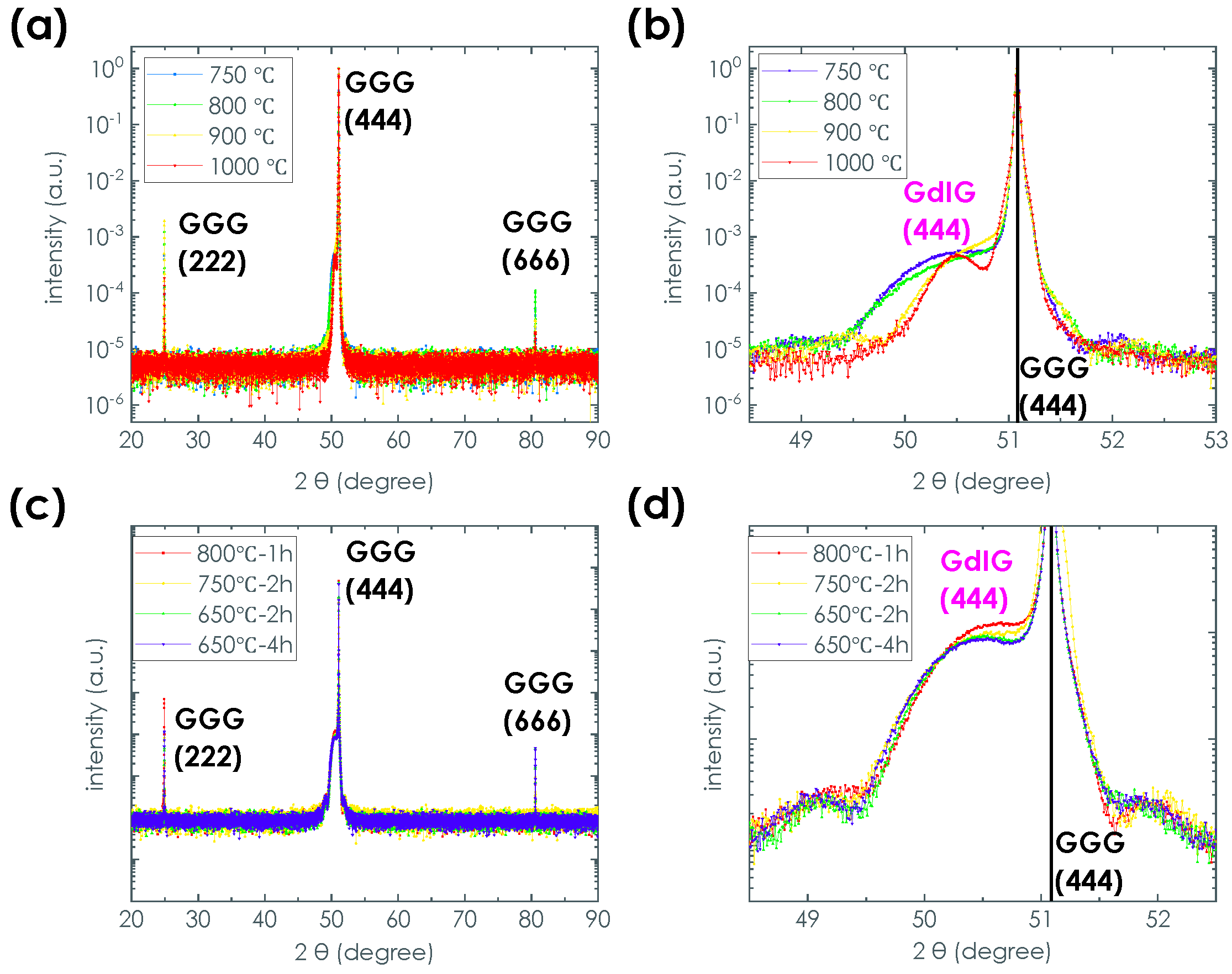
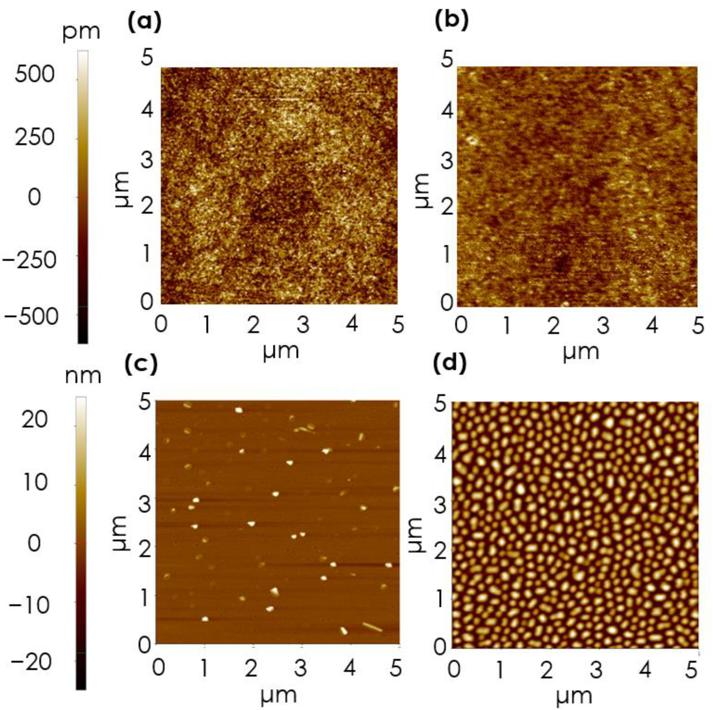
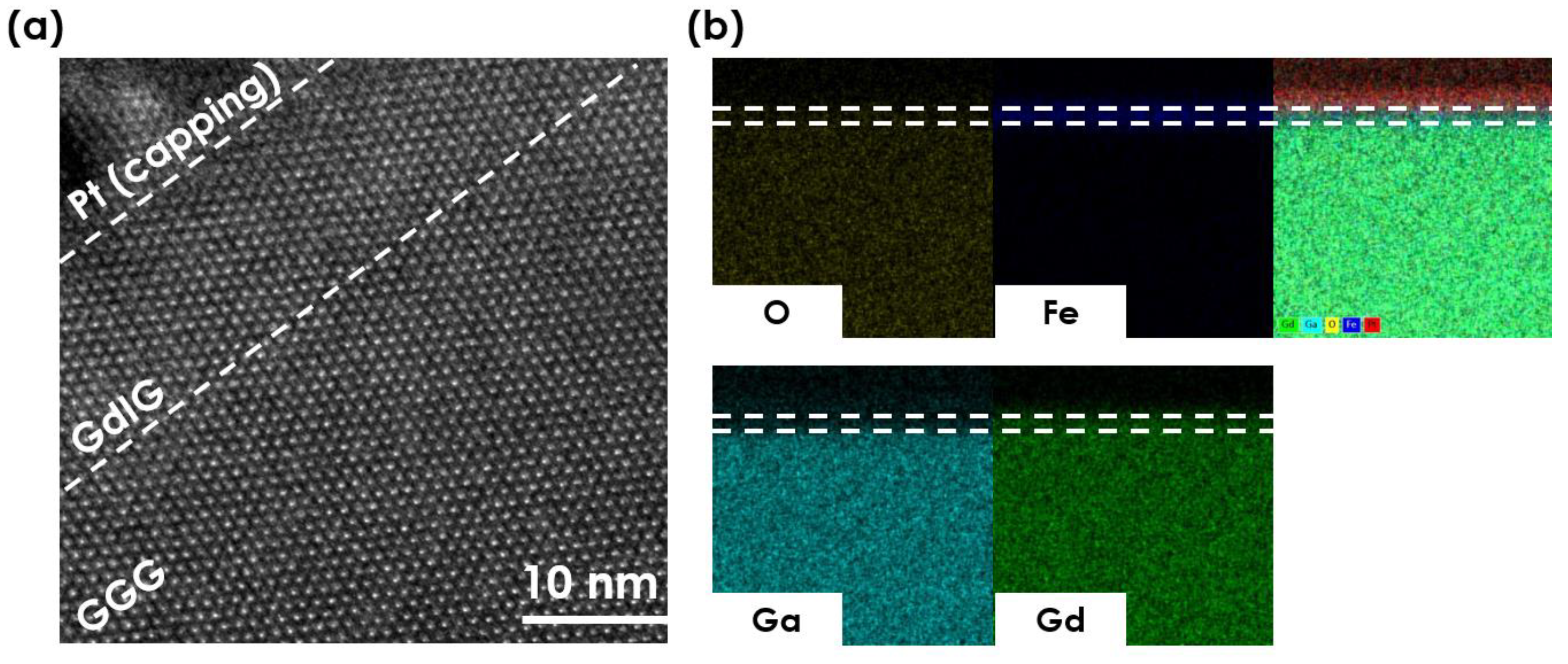
3.1. Structural Properties

To find the optimal post-annealing temperature for crystal formation, we first deposited a GdIG sample, targeting 10 nm thickness on the GGG substrate. Figure 1a,b show the measured XRD spectrum of deposited GdIG samples for various annealing temperatures. GGG (444) peak appears at 51.2°, which indicates that the lattice constant of GGG is 12.37 Å. Next to GGG (444) peak, a broad peak is observed at 50.3°, which corresponds to the GdIG (444) peak with a lattice constant of 12.55 Å. We note that the lattice constant of GdIG on GGG is larger than that of a single crystalline GdIG of 12.48 Å due to the pseudo-morphic growth on the GGG substrate [15]. We confirmed that there is no extra peak in the entire XRD pattern (Figure 1a) except for 111 orientation, suggesting the high epitaxial quality of GdIG. The thickness of GdIG was confirmed using a fringe pattern in the XRD spectrum. For the 750 °C annealed sample, the first and second fringe peaks were observed at 52.08° and 52.98°, from which the thickness of GdIG was estimated to be 11 ± 2 nm. This confirms that the thickness of GdIG is almost the same as what we targeted.
As shown in Figure 1b, the increased annealing temperature drives GdIG peak shaper. As the broadening of XRD peak is caused by vacancy- or defect-driven lattice expansion, the XRD result suggests that the higher annealing temperature results in better crystallinity [5]. We also confirmed that annealing time does not exert any significant change in the XRD pattern (Figure 1c). This suggests that crystallinity is predominantly governed by the annealing temperature.
However, we find that the high annealing temperature can affect the surface topography. The surface topography map measured using AFM in the non-contact mode (Figure 2) shows a significant change in surface morphology as annealing temperature increases. The roughness of film surface is about 0.1 nm order for the 750 °C and 800 °C annealed samples (see Table 1). However, the surface morphology of GdIG changes abruptly above 900 °C, and the island starts to appear. For 1000 °C annealed samples, island growth becomes the dominant film formation mechanism, resulting in the entire area being covered with islands of ~200 nm diameter and ~20 nm height.
As the purpose of this work is to deposit uniform film for spin wave application, we selected 750 °C postannealed sample and performed additional measurement using TEM to ensure the crystallinity. TEM measurement was conducted using the STEM (scanning transmission electron microscope) system with Cs-corrector (JEM-2100F) designed by JEOL. A high-resolution TEM image in Figure 3a shows that GdIG and GGG have a smooth interface with a continuous crystal structure above and below the interface due to a similar lattice constant between the two materials. Additionally, a clear separation of Fe in the GdIG film and Ga in the GGG substrate from energy dispersive X-ray spectroscopy (EDX) (Figure 3b) indicates minimal mixing between GdIG and substrate.

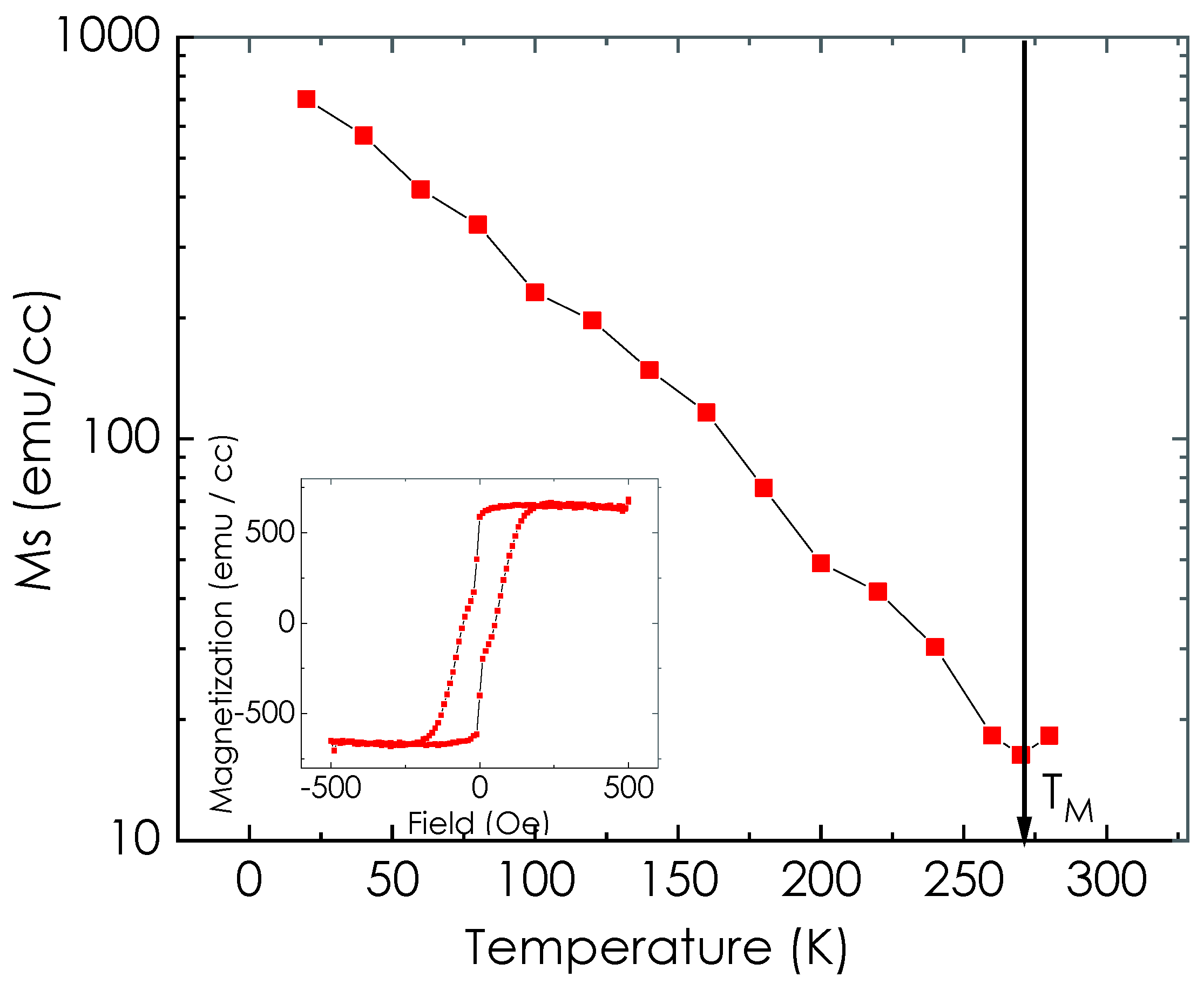
3.2. Magnetic Property

The magnetic property was checked as an additional measure to ensure crystallinity and stoichiometry. Temperature dependent magnetometry of 10 nm GdIG sample annealed at 750 °C was performed using SQUID VSM in MPMS 3. An M-T curve was obtained by measuring M-H curves under in-plane magnetic field at various temperatures and extracting the saturation magnetization (MS). We eliminated paramagnetic contribution from GGG substrate by subtracting the linear background in the M-H curve at each temperature.
Figure 4 shows the extracted M-T curve. We focus on the value of MS at low temperatures and the magnetic compensation point. MS at 20 K was about 700 emu/cc, similar to previous reports as shown in Table 2. Magnetic compensation point appeared near 270 K also agrees with references on bulk and thin film GdIG [9,16,17].

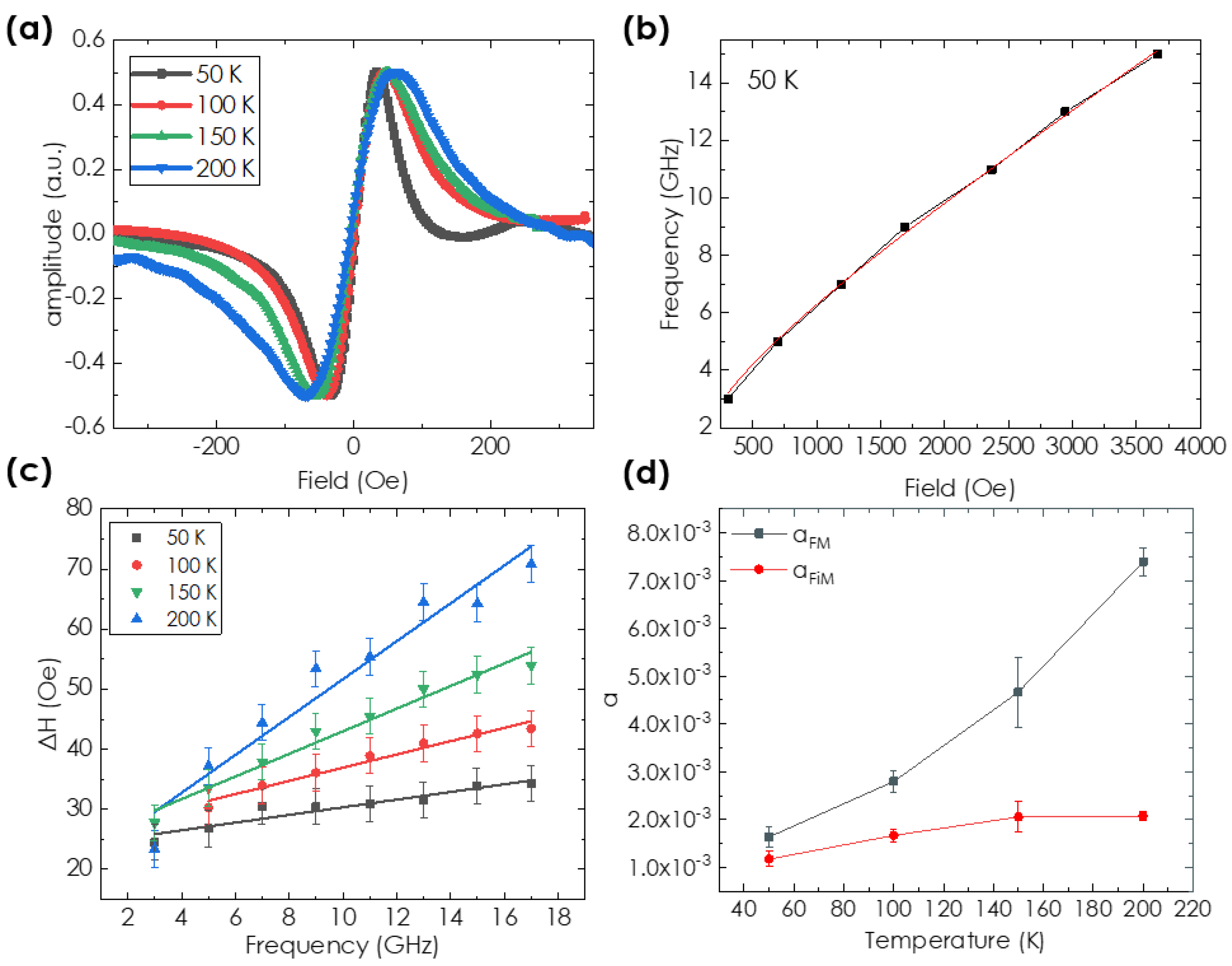
3.3. FMR Measurement

Finally, the damping parameter of the GdIG sample was measured using the temperature dependent FMR. We used 60-nanometer-thick GdIG sample to enhance RF absorption power. Temperature and field control was performed using a physical property measurement system (PPMS). RF field for FMR was applied using a custom-built FMR setup that is compatible with PPMS.
Figure 5a shows the FMR spectra of the GdIG film for various temperatures. Here, we fixed the excitation frequency (15 GHz) and swept the magnetic field from 0 to 5000 Oe along the in-plane direction. Figure 5b shows resonance frequency as a function of external magnetic field for T = 50 K. The exact overlap with Kittel formula (red solid line) was observed. We extracted the damping parameter from the spectrum by measuring peak to peak distance from the FMR lineshape in Figure 5a. We first use the model for conventional ferromagnetic material to obtain damping parameter α F M :
Δ H = Δ H 0 + 4 π α F M 3 γ e f f f
where γ e f f = g e f f μ B / = Δ M / Δ S is the effective gyromagnetic ratio of the net moment, and Δ M and Δ S are the differences in the net moment and the spin density of two sublattices, respectively. Figure 5c shows Δ H as a function of frequency for several temperaures. The slope increases with increasing temperaure. Considering that the temperature variation of γ e f f is small, as seen in Table 3, the result suggests that α F M increased with increasing temperature, which we ascribed to the divergence of α F M at angular momentum compensation point (TA) [18,19,20].
In the case of ferrimagnet, however, the dissipation rate from the two lattices and the dependence of resonance frequency on net spin density need to be considered to deduce a well-defined damping constant [18,19,20,21]. Since the GdIG sample also can be regarded as a compensated ferrimagnet with two effective sublattices, damping α F i M is expressed as follows:
α F i M = | s n e t | | s t o t a l | α F M
where s n e t = s 1 s 2 and s t o t a l = s 1 + s 2 are the difference and the sum of the spin density for each sublattice ( s 1 , 2 ), respectively.
To estimate α F i M , we should extract the spin density of each sublattice in GdIG. This was achieved by using the M-T curve shown in Figure 4 and by assuming that the spin density of the Fe sublattice follows the same trend with that in YIG [16]. As shown in Figure 5d, α F i M had no singular behavior close to angular momentum compensation in contrast to α F M , and this dependence corresponds to previous reports on α F i M of compensated ferrimagnets, including metallic GdFeCo [20].
We note that the GdIG sample deposited by the MOD method has comparable damping constant to some of the literature on spin wave applications [22,23]. In the case of the 10 nm YIG sample grown by the Pulsed Laser Deposition (PLD) method, an order of 103 damping parameter was obtained, which is similar to our result [24]. Our data also suggest that the MOD-deposited GdIG can be an alternative platform that could be used for low-temperature magnonic applications.

4. Conclusions

A high-quality GdIG thin film on GGG substrate was prepared using the MOD method. We found that a transition of the growing model of GdIG occurs at around 900 °C above which the film grows with an island pattern. The optimal postannealing temperature was decided based on the growth mode of the film and the crystallinity confirmed by the TEM. Temperature dependence of magnetization was measured using SQUID VSM and confirmed that TM was measured at 270 K. FMR measurement showed that MOD deposited GdIG exhibits comparable damping constant to various deposition methods. Moreover, our experiment found that the damping constant of GdIG decreased at lower temperatures. We expect that the MOD method provides a simple and high-throughput procedure to deposit GdIG, which has potential advantages for magnonic applications.

Author Contributions

K.-J.K. and J.-R.J. planned and supervised the study. P.-C.V. deposited the GdIG sample; H.J. and J.-W.Y. performed the FMR measurement. J.Y. measured AFM; Y.J. measured MPMS; H.K. and A.M.P. analyzed the data from AFM, XRD, FMR, TEM, EDX, and MPMS and wrote the manuscript. All authors were involved in the discussion of the results and commented on the manuscript. All authors have read and agreed to the published version of the manuscript.

Funding

This research was supported by the National Research Foundation of Korea (NRF) funded by the Korean Government (MSIP) (grant numbers: 2016R1A5A1008184, and 2020R1A2C100613612) and by KAIST; funded Global Singularity Research Program for 2021; and by Samsung Research Funding & Incubation Center of Samsung Electronics under Project Number SRFC-MA2002-02. Y.J. acknowledges the support by KBSI grant (No. D210200).

Institutional Review Board Statement

Not applicable.

Informed Consent Statement

Not applicable.

Data Availability Statement

Derived data supporting the findings of this study are available from the corresponding author (A.M.P., J.-R.J. and K.-J.K.) on request.

Conflicts of Interest

The authors declare no conflict of interest.

Abbreviations

The following abbreviations are used in this manuscript:
MODMetal Organic Decomposition;
FMRFerromagnetic resonance;
REIGRare Earth Iron garnet;
YIGYttrium Iron garnet;
GdIGGadolinium Iron garnet;
GGGGadolinium Gallium Garnet;
AFMAtomic Force Microscopy;
XRDX-ray Diffraction;
TEMTransmission of Electron Microscope;
EDXEnergy Dispersive X-ray spectroscopy;
PVPPolyVinylPyrrolidone;
DMFDiMethylFormamide;
SQUIDSuperconducting Quantum Interference Vibrating System;
VSMVibrational Sample Magnetometer;
PPMSPhysical Property Measurement System;
MPMSMagnetic Property Measurement System;
PLDPulsed Laser Deposition.

References

  1. Keffer, F.; Kittel, C. Theory of antiferromagnetic resonance. Phys. Rev. 1952, 85, 329. [Google Scholar] [CrossRef]
  2. Keffer, F.; Kaplan, H.; Yafet, Y. Spin Waves in Ferromagnetic and Antiferromagnetic Materials. Am. J. Phys. 1953, 21, 253. [Google Scholar] [CrossRef]
  3. Kim, C.; Lee, S.; Kim, H.G.; Park, J.H.; Moon, K.W.; Park, J.Y.; Yuk, J.M.; Lee, K.J.; Park, B.G.; Kim, S.K.; et al. Distinct handedness of spin wave across the compensation temperatures of ferrimagnets. Nat. Mater. 2020, 19, 980–985. [Google Scholar] [CrossRef] [PubMed]
  4. Zhang, S.; Li, Z. Roles of nonequilibrium conduction electrons on the magnetization dynamics of ferromagnets. Phys. Rev. Lett. 2004, 93, 127204. [Google Scholar] [CrossRef] [Green Version]
  5. Cao Van, P.; Surabhi, S.; Dongquoc, V.; Kuchi, R.; Yoon, S.G.; Jeong, J.R. Effect of annealing temperature on surface morphology and ultralow ferromagnetic resonance linewidth of yttrium iron garnet thin film grown by rf sputtering. Appl. Surf. Sci. 2018, 435, 377–383. [Google Scholar] [CrossRef]
  6. Gomi, M.; Tanida, T.; Abe, M. Rf sputtering of highly Bi-substituted garnet films on glass substrates for magneto-optic memory. J. Appl. Phys. 1985, 57, 3888. [Google Scholar] [CrossRef]
  7. Lee, H.; Yoon, Y.; Kim, S.; Yoo, H.K.; Melikyan, H.; Danielyan, E.; Babajanyan, A.; Ishibashi, T.; Friedman, B.; Lee, K. Preparation of bismuth substituted yttrium iron garnet powder and thin film by the metal-organic decomposition method. J. Cryst. Growth 2011, 329, 27–32. [Google Scholar] [CrossRef]
  8. Uchida, T.; Watanabe, S.; Uchiyama, T.; Tachiki, T. Fabrication of STO buffer films on MgO substrates by the MOD method. J. Phys. Conf. Ser. 2008, 97, 012057. [Google Scholar] [CrossRef]
  9. Geprägs, S.; Kehlberger, A.; Coletta, F.D.; Qiu, Z.; Guo, E.J.; Schulz, T.; Mix, C.; Meyer, S.; Kamra, A.; Althammer, M.; et al. Origin of the spin Seebeck effect in compensated ferrimagnets. Nat. Commun. 2016, 7, 10452. [Google Scholar] [CrossRef] [Green Version]
  10. Liu, G.; Wang, X.; Luan, Z.Z.; Zhou, L.F.; Xia, S.Y.; Yang, B.; Tian, Y.Z.; Guo, G.; Du, J.; Wu, D. Magnonic Unidirectional Spin Hall Magnetoresistance in a Heavy-Metal–Ferromagnetic-Insulator Bilayer. Phys. Rev. Lett. 2021, 127, 207206. [Google Scholar] [CrossRef]
  11. Dong, B.W.; Cramer, J.; Ganzhorn, K.; Yuan, H.Y.; Guo, E.J.; Goennenwein, S.T.B.; Klaui, M. Spin Hall magnetoresistance in the non-collinear ferrimagnet GdIG close to the compensation temperature. J. Phys. Condens. Matter 2018, 30, 035802. [Google Scholar] [CrossRef]
  12. Thi, T.N.; Van, P.C.; Viet, D.D.; Quoc, V.D.; Ahn, H.; Cao, V.A.; Kang, M.G.; Nah, J.; Park, B.G.; Jeong, J.R. Morphology-dependent spin Seebeck effect in yttrium iron garnet thin films prepared by metal-organic decomposition. Ceram. Int. 2021, 47, 16770–16775. [Google Scholar] [CrossRef]
  13. Zhang, D.; Jin, L.; Zhang, H.; Yang, Q.; Rao, Y.; Wen, Q.; Zhou, T.; Liu, C.; Zhong, Z.; Xiao, J.Q. Chemical epitaxial growth of nm-thick yttrium iron garnet films with low Gilbert damping. J. Alloys Compd. 2017, 695, 2301–2305. [Google Scholar] [CrossRef]
  14. Dongquoc, V.; Kuchi, R.; Van, P.C.; Surabhi, S.; Lee, S.W.; Kim, D.; Jeong, J.R. Enhancing magneto-optical and structural properties of Bi-YIG thin film on glass substrate using poly[vinylpyrrolidone](PVP) assisted MOD method. Ceram. Int. 2019, 45, 20758–20761. [Google Scholar] [CrossRef]
  15. Yang, B.; Xia, S.Y.; Zhao, H.; Liu, G.; Du, J.; Shen, K.; Qiu, Z.; Wu, D. Revealing thermally driven distortion of magnon dispersion by spin Seebeck effect in Gd3Fe5O12. Phys. Rev. B 2021, 103, 054411. [Google Scholar] [CrossRef]
  16. Liensberger, L.; Kamra, A.; Maier-Flaig, H.; Geprägs, S.; Erb, A.; Goennenwein, S.T.B.; Gross, R.; Belzig, W.; Huebl, H.; Weiler, M. Exchange-enhanced ultrastrong magnon-magnon coupling in a compensated ferrimagnet. Phys. Rev. Lett. 2019, 123, 117204. [Google Scholar] [CrossRef] [Green Version]
  17. Becker, S.; Ren, Z.; Fuhrmann, F.; Ross, A.; Lord, S.; Ding, S.; Wu, R.; Yang, J.; Miao, J.; Kläui, M.; et al. Magnetic Coupling in Y3Fe5O12/Gd3Fe5O12 Heterostructures. Phys. Rev. Appl. 2021, 16, 014047. [Google Scholar] [CrossRef]
  18. Isaac, N.; Ruizi, L.; Zheyu, R.; Se kwon, K.; Qiming, S. Survey of temperature dependence of the damping parameter in the ferrimagnet Gd3Fe5O12. IEEE Trans. Magn. 2022, 58, 1–13. [Google Scholar] [CrossRef]
  19. Kim, D.H.; Okuno, T.; Kim, S.K.; Oh, S.H.; Nishimura, T.; Hirata, Y.; Futakawa, Y.; Yoshikawa, H.; Tsukamoto, A.; Tserkovnyak, Y.; et al. Low Magnetic Damping of Ferrimagnetic GdFeCo Alloys. Phys. Rev. Lett. 2019, 122, 127203. [Google Scholar] [CrossRef] [Green Version]
  20. Okuno, T.; Kim, S.K.; Moriyama, T.; Kim, D.H.; Mizuno, H.; Ikebuchi, T.; Hirata, Y.; Yoshikawa, H.; Tsukamoto, A.; Kim, K.J.; et al. Temperature dependence of magnetic resonance in ferrimagnetic GdFeCo alloys. Appl. Phys. Express 2019, 12, 093001. [Google Scholar] [CrossRef]
  21. Kim, K.J.; Kim, S.K.; Hirata, Y.; Oh, S.H.; Tono, T.; Kim, D.H.; Okuno, T.; Ham, W.S.; Kim, S.; Go, G.; et al. Fast domain wall motion in the vicinity of the angular momentum compensation temperature of ferrimagnets. Nat. Mater. 2017, 16, 1187–1192. [Google Scholar] [CrossRef] [Green Version]
  22. Jungfleisch, M.B.; Chumak, A.V.; Kehlberger, A.; Lauer, V.; Kim, D.H.; Onbasli, M.C.; Ross, C.A.; Kläui, M.; Hillebrands, B. Thickness and power dependence of the spin-pumping effect in Y3Fe5O12/Pt heterostructures measured by the inverse spin Hall effect. Phys. Rev. B 2015, 91, 134407. [Google Scholar] [CrossRef] [Green Version]
  23. Jungfleisch, M.B.; Zhang, W.; Jiang, W.; Chang, H.; Sklenar, J.; Wu, S.M.; Pearson, J.E.; Bhattacharya, A.; Ketterson, J.B.; Wu, M.; et al. Spin waves in micro-structured yttrium iron garnet nanometer-thick films. J. Appl. Phys. 2015, 117, 17D128. [Google Scholar] [CrossRef] [Green Version]
  24. Jermain, C.L.; Aradhya, S.V.; Reynolds, N.D.; Buhrman, R.A.; Brangham, J.T.; Page, M.R.; Hammel, P.C.; Yang, F.Y.; Ralph, D.C. Increased low-temperature damping in yttrium iron garnet thin films. Phys. Rev. B 2017, 95, 174411. [Google Scholar] [CrossRef] [Green Version]
Figure 1. XRD spectrum for GdIG samples annealed at various annealing temperatures (a) from 20° to 90° and (b) from 48.5° to 53°. XRD spectrum for GdIG samples annealed at various annealing times (c) from 20° to 90° and (d) from 48.5° to 53°.
Magnetochemistry 08 00028 g001
Figure 2. AFM image of (a) 750 °C, (b) 800 °C, (c) 900 °C, and (d) 1000 °C annealed samples.
Magnetochemistry 08 00028 g002
Figure 3. (a) TEM and (b) EDX images of 750 °C annealed GGG|GdIG sample. As GGG and GdIG have similar structure and lattice parameters, a smooth interface appears, indicating an epitaxial growth of GdIG. (b) The presence of Gd and Fe and the absence of Ga at the marked region represent the formation of the GdIG layer.
Magnetochemistry 08 00028 g003
Figure 4. M-T curve of GdIG 10 nm thin film post-annealed at 750 °C. Inset shows the M-H curve at 20 K.
Magnetochemistry 08 00028 g004
Figure 5. (a) FMR spectra of GdIG 60 nm samples at 15 GHz RF frequency. The horizonal axis (field axis) is shifted as much as the resonance field to compare the linewidth for different temperatures. (b) Resonance frequency as a function of the external field at 50 K and the Kittel formula fitting (red line). (c) Frequency dependence of peak-to-peak FMR linewidth. The solid line represents linear fitting. (d) Temperature dependence of damping parameters α F M and α F i M .
Magnetochemistry 08 00028 g005
Table 1. Roughness of films (Ra) for several annealing temperatures.
Annealing Temperature (°C)Ra (nm)
7500.14
8000.08
9000.71
10008.71
Table 2. Compensation temperature TM and saturation magnetization (Ms) at 20 K of GdIG.
SourceTMMs (emu/cc)
From Figure 4270 K700
From [16]280 K600
From [17]300 K670
From [9]280 K1300
Table 3. Effective gyromagnetic ratio ( γ e f f ) and damping parameter ( α F M ) measured at various temperatures below TM.
Temperature (K)γeff (×107 T−1s−1) α F M (×10−3)
501.78 ± 0.081.60 ± 0.22
1001.85 ± 0.072.80 ± 0.22
1501.81 ± 0.024.67 ± 0.74
2001.75 ± 0.087.41 ± 0.3
Publisher’s Note: MDPI stays neutral with regard to jurisdictional claims in published maps and institutional affiliations.

