Article

Manipulation of Time- and Frequency-Domain Dynamics by Magnon-Magnon Coupling in Synthetic Antiferromagnets

1
Shanghai Key Laboratory of Special Artificial Microstructure Materials and Technology, School of Physics Science and Engineering, Tongji University, Shanghai 200092, China
2
Key Laboratory of Micro and Nano Photonic Structures (MOE), School of Information Science and Technology, Fudan University, Shanghai 200433, China
*
Authors to whom correspondence should be addressed.
Magnetochemistry 2022, 8(1), 7; https://doi.org/10.3390/magnetochemistry8010007
Submission received: 1 December 2021 / Revised: 17 December 2021 / Accepted: 27 December 2021 / Published: 30 December 2021
(This article belongs to the Special Issue Advances in Antiferromagnetic Spintronics)

Abstract

:
Magnons (the quanta of spin waves) could be used to encode information in beyond Moore computing applications. In this study, the magnon coupling between acoustic mode and optic mode in synthetic antiferromagnets (SAFs) is investigated by micromagnetic simulations. For a symmetrical SAF system, the time-evolution magnetizations of the two ferromagnetic layers oscillate in-phase at the acoustic mode and out-of-phase at the optic mode, showing an obvious crossing point in their antiferromagnetic resonance spectra. However, the symmetry breaking in an asymmetrical SAF system by the thickness difference, can induce an anti-crossing gap between the two frequency branches of resonance modes and thereby a strong magnon-magnon coupling appears between the resonance modes. The magnon coupling induced a hybridized resonance mode and its phase difference varies with the coupling strength. The maximum coupling occurs at the bias magnetic field at which the two ferromagnetic layers oscillate with a 90° phase difference. Besides, we show how the resonance modes in SAFs change from the in-phase state to the out-of-phase state by slightly tuning the magnon-magnon coupling strength. Our work provides a clear physical picture for the understanding of magnon-magnon coupling in a SAF system and may provide an opportunity to handle the magnon interaction in synthetic antiferromagnetic spintronics.

1. Introduction

Magnon spintronics [1], which utilize propagating spin waves for nanoscale transmission and processing of information, have been growing as emerging research fields [2]. As a carrier of spin current, the magnons hold the promise of delivering information without the motion of electrons, therefore avoiding Ohmic losses and becoming a promising alternative to CMOS-based circuits. Recently, the magnons in antiferromagnets have attracted fundamental interest [3,4,5], in which long wavelength magnons can have frequency in the gigahertz (GHz), sub-terahertz, and even terahertz (THz) ranges because of the spin-sublattice exchange [6,7,8]. Due to the presence of two sublattices in antiferromagnets (AFMs) or ferrimagnets, the ferromagnetic resonance (FMR) spectra possess two different magnon branches. These two magnon modes can merge into a single branch at a degeneracy point, at which strong magnon-magnon interactions occur. This was reported in a layered AFM crystal CrCl3 [9,10], compensated ferrimagnet gadolinium iron garnet [11], or magnetic metal-insulator hybrid structure [12,13]. Interestingly, the tunable magnon-magnon coupling in these systems provides the opportunity to use interactions between the magnon branches as a means to control/manipulate magnons in the device-based antiferromagnetic spintronics.
In contrast, synthetic antiferromagnets (SAFs) [14,15], composed of two ferromagnetic (FM) layers separated by a non-magnetic layer, could provide an easy way to handle the magnon-magnon interactions, because the interlayer coupling between the two FM layers mainly comes from the Ruderman–Kittel–Kasuya–Yosida (RKKY) interaction [16,17] and its strength is adjustable. The antiferromagnetically coupled two FM layers possess two kinds of uniform precession resonance modes: in-phase acoustic mode (AM) and out-of-phase optic mode (OM) [18,19,20,21]. Recently, it was shown that in a symmetrical SAF the symmetry-protected mode crossing in FMR spectra between the acoustic and optic mode branches can be eliminated by a tilting bias magnetic field [22,23] or by dynamic dipolar interaction from nonuniform precession of magnetic moments [24]. Subsequently, a strong magnon-magnon coupling between the AM and OM appears in the SAF systems. Besides, the SAFs with two asymmetric ferromagnetic sublayers (different thickness or different materials) can also break the system symmetry and realize the strong magnon-magnon coupling [23,25].
One of the important conditions to realize magnon-magnon coupling in the SAFs is to turn the two distant modes (AM and OM) into resonance at very close frequency, from which a new spin wave state can be generated, namely, mode hybridization. An obvious feature of the magnon hybridization state is the appearance of an anti-crossing gap in frequency spectra between the acoustic and optic branches. The strength of the magnon-magnon coupling can be characterized by the gap size [9]. Recently, the maximum coupling strength of 9.94 GHz was predicted [23]. However, most previous studies so far have focused on how to achieve magnon-magnon coupling or how to enhance the coupling strength, and less study is concerned with the magnetization precession of the hybrid modes. In this work, we will analytically and numerically study the magnetization dynamics of magnon-magnon coupling in both symmetrical and asymmetrical CoFeB-based SAFs. We find that a clear frequency crossing between the optic and acoustic magnon modes appear in a symmetrical SAF, indicating the absence of magnon coupling due to symmetry protection. However, for an asymmetrical SAF with different thicknesses of the two FM sublayers, a coupling gap is achieved because of the intrinsic symmetry breaking of the system. Remarkably, the strongest magnon-magnon coupling between the two magnon modes generates a hybrid precession mode with the phase difference of δ φ = 90 ° between the two magnetic sublattices, rather than the in-phase AM magnons ( δ φ = 0 ° ) and out-of-phase OM magnons ( δ φ = 180 ° ).

2. Simulation Model

As illustrated in Figure 1, we consider an SAF nanopillar structure of CoFeB (d1 nm)/Ru/CoFeB (d2 nm) trilayer patterned in a circular shape of 100 nm × 100 nm. Here we consider two samples: One is symmetric SAF structure with d1 = d2 = 2.0 nm (Sample-I) and the other is an asymmetric SAF with d1 = 2.0 nm and d2 = 4.0 nm (Sample-II). In this study, the dynamics of the trilayer samples were simulated by using the open-source simulation software OOMMF (National Institute of Standards and Technology, Gaithersburg, MD, USA) [26], which is based on the Landau–Lifshitz–Gilbert equation:
d m i d t = γ m i × H i , eff + α m i × d m i d t
where m i = M i / M s is the unit magnetization vector of the ith discretization cell in upper or lower CoFeB layers. Ms is the saturation magnetization of CoFeB, α is the Gilbert damping factor, and γ is the gyromagnetic ratio. Heff is the effective magnetic field that includes the intralayer exchange field, demagnetizing field Hd, interlayer exchange field HIEC between the upper and lower CoFeB, and external magnetic field H0. The effective magnetic field is:
H eff = 2 A e x μ 0 M s 2 m + H d + H IEC + H 0
where Aex is the exchange stiffness, μ0 is the vacuum permeability. H IEC = J IEC / ( d j M s ) , here JIEC is the interlayer exchange coupling constant, with JIEC > 0 for ferromagnetic coupling while JIEC < 0 for antiferromagnetic coupling. dj is the thickness of CoFeB layer (j = 1 or 2 refers to the upper or lower layer). In this study, we suppose the thickness of non-magnetic layer (dRu) is 1.1 nm (the second peak of antiferromagnetic coupling) [21]. Additionally, the typical material parameters of CoFeB (in CGS units) are used [27,28]: M s = 1000   emu / cm 3 , A e x = 2.0 × 10 6   erg / cm , α = 0.01 and J IEC = 0.2   erg / cm 2 . Here, the magnetic anisotropy is ignored because its energy is almost unaffected by the in-plane orientation of the sublayer magnetizations [23,24]. All the simulations are performed without taking temperature into account.

3. Results and Discussion

Firstly, we start our simulations for calculating the static hysteresis loops of two different samples and the results are shown in Figure 1. The external magnetic field H0 is along the x-direction. For the symmetrical SAF (Sample-I), as shown in Figure 1a,c, there are only two equilibrium states: spin-canted state and parallel saturation state. Without the external magnetic field, the initial state of m 1 and m 2 are antiparallelly aligned due to the antiferromagnetic coupling. Under the action of H0 with the strength of 0 < H 0 < H s , the m 1 and m 2 are rotated into a spin-canted state within the film plane, where Hs = 2HIEC represents the saturation magnetic field. The angles between mi and H0 satisfy: φ2 = −φ1 = cos−1(H0/Hs). When H 0 > H s , the m 1 and m 2 orient parallel to the direction of bias magnetic field (i.e., x-axis). Taking the parameter values of M s , d, and JIEC, we get the strength of HIEC = 1100 Oe, which is in good agreement with the simulation results (the saturation field Hs = 2300 Oe and thereby HIEC = Hs/2 = 1150 Oe).
For the asymmetrical SAF (Sample-II), however, as shown in Figure 1b,d, three typical equilibrium states exist. When the magnetic field is smaller than the critical field [18] H cri , 1 = H IEC 1 H IEC 2 , the magnetization vectors of m 1 and m 2 are opposite to each other along the x-direction and the net magnetization is constant. Above the critical field, the magnetizations of two FMs deviate from the antiparallel alignment. The field dependent magnetization can be estimated as [20,29]:
M ( H ) M s = d 1 cos ( φ 1 e q ) + d 2 cos ( φ 2 e q ) d 1 + d 2
where φ 1 e q and φ 2 e q represent the equilibrium directions of m 1 and m 2 . When the external field H0 is larger than H cri , 2 = H IEC 1 + H IEC 2 , both m 1 and m 2 are forced to align in the x-direction and the SAF reaches a saturation state.

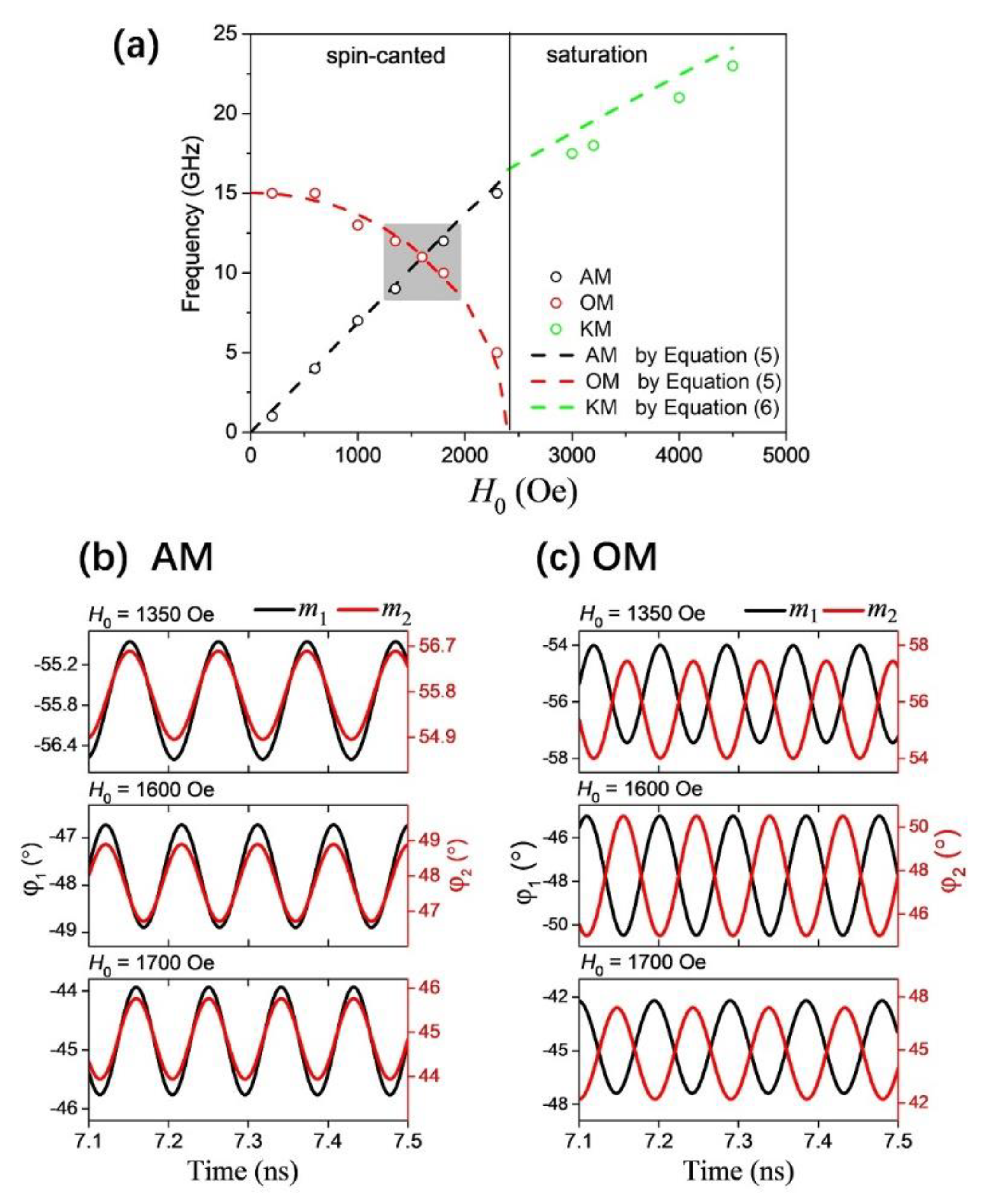
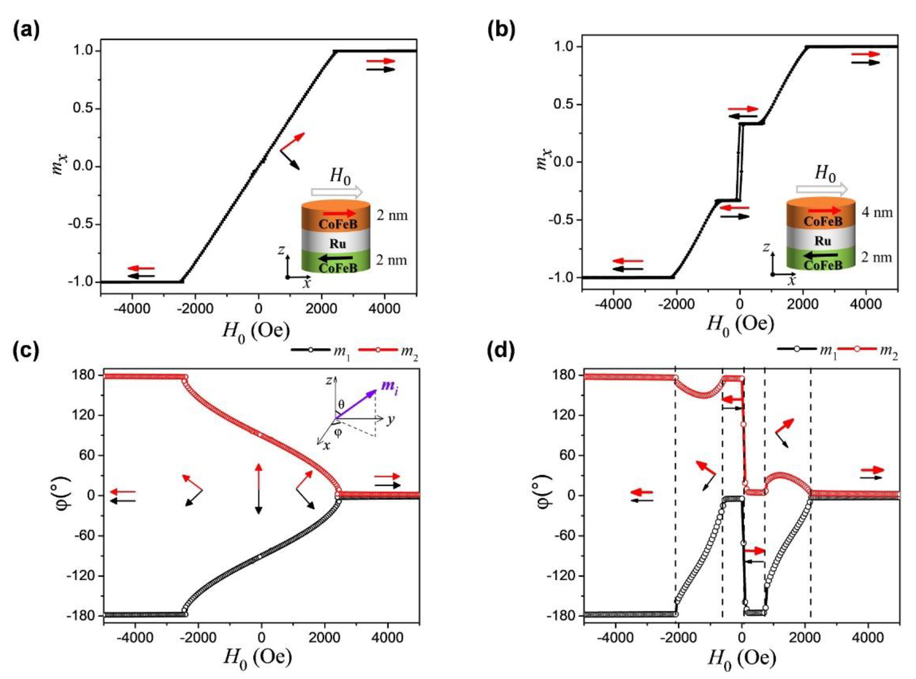
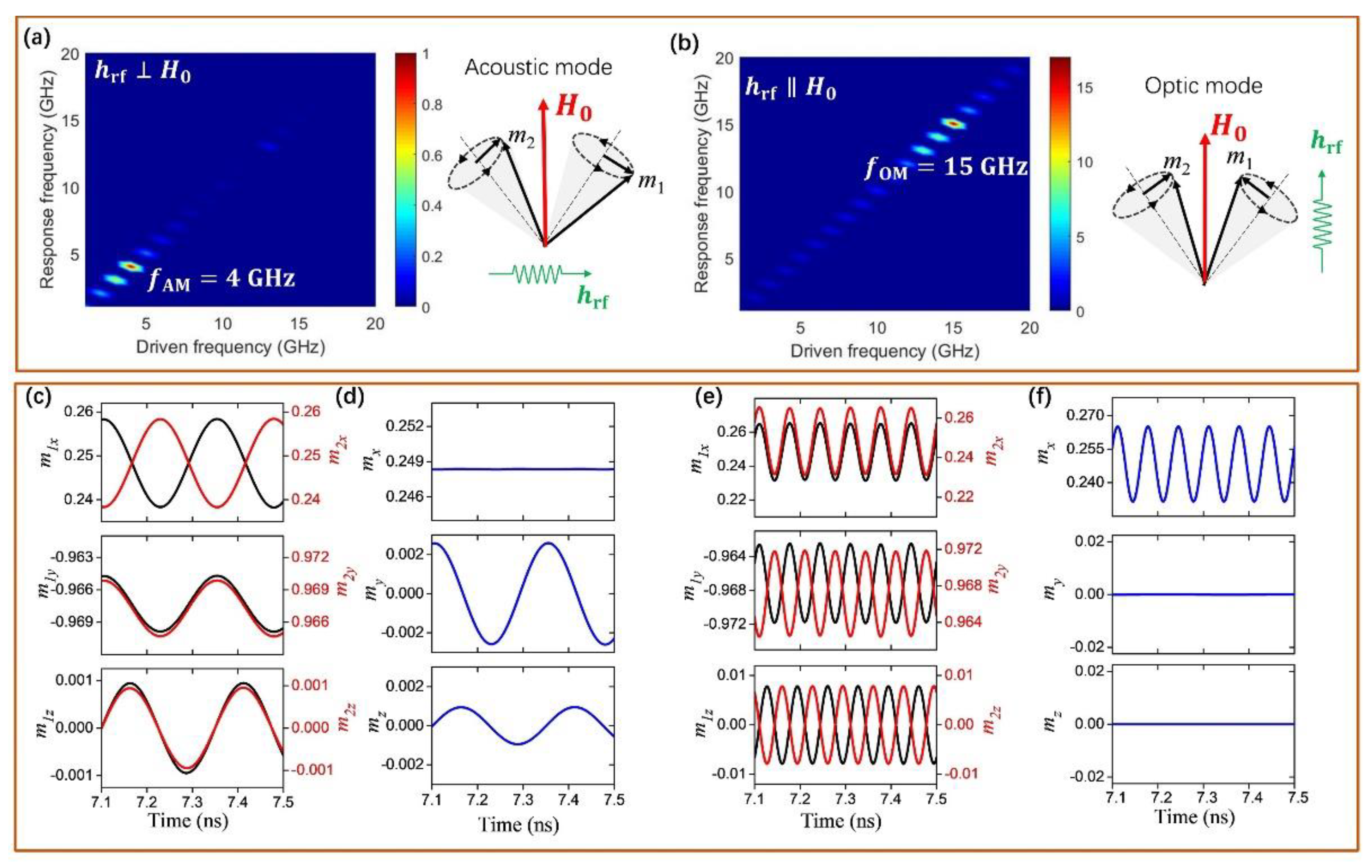
3.1. Dynamic Resonance Properties of Symmetrical SAF

In this part, we study the dynamics of antiferromagnetic resonance. In addition to an external bias field applied along the x-axis to stabilize the magnetizations of SAFs, we also apply a time-varying microwave field of h rf = h 0 sin ( 2 π f t ) to excite the magnons. The oscillation amplitude of the microwave fields is small and set as h 0 = 3 Oe in this study. Its direction is either along the x-axis (i.e., h rf H 0 , namely, longitudinal pumping) or along the y-axis (i.e., h rf H 0 , namely, transverse pumping). The time evolution of spatially averaged magnetizations ( m 1 and m 2 ) are recorded to calculate the response frequency through fast Fourier transform (FFT) analysis.
It is well known that an SAF system inherently has two distinct eigenmodes: AM and OM [18,19]. Figure 2 summarizes the simulated results at H0 = 600 Oe for a symmetrical SAF with two identical FM layers (d1 = d2 = 2.0 nm). In the case of transverse pumping, only AM resonance is excited at a low frequency of 4 GHz while for the longitudinal pumping case only OM resonance is excited at a high frequency of 15 GHz, as shown in Figure 2a,b, respectively. This result can be well explained as follows: by considering that the resonance response signal is characterized by the rf components of the net magnetization m = ( m 1 + m 2 ) / 2 along the pumping field direction. For the low frequency resonance state, as shown in Figure 2c, d, both y- and z-components of m 1 and m 2 precess in phase while the x-component oscillates out-of-phase. In contrast, for the high frequency resonance state, as shown in Figure 2e,f, the x-component of m 1 and m 2 precess in-phase while both y- and z-components precess out-of-phase. Therefore, for the AFMR measurement with a transverse pumping microwave field (along the y-axis) to the bias magnetic field (x-axis), the in-phase AM resonance state (taken from the my or mz) is only observed while the OM resonance state is hidden. In contrast, for the longitudinal pumping microwave field (along the x-axis), the observed resonance signal comes from the net magnetization mx (because the net my = 0 or mz = 0) but we classify this resonance state as the OM state due to the out-of-phase in my (or mz) component.
Figure 3a shows the dispersion relation of frequency versus external magnetic field H0 applied in the x-direction. In the spin-canted region, the frequency of the in-phase AM fAM increases with the increasing field while the out-of-phase OM frequency fOM decreases gradually until it reaches zero at the critical filed H s = 2300   Oe. Theoretically, we could assume the whole FM layer is a single-domain and possesses a uniform magnetization precession within each layer. Thus, within the macrospin approximation, Equation (1) can be expanded as:
d m 1 d t = γ m 1 × ( H 0 x H IEC , 1 m 2 4 π M s ( m 1 · z ) z ) + α m 1 × d m 1 d t   d m 2 d t = γ m 2 × ( H 0 x H IEC , 2 m 1 4 π M s ( m 2 · z ) z ) + α m 2 × d m 2 d t  
For any given applied field, Equation (4) has two real solutions, corresponding to the acoustic and optic modes. Additionally, for the symmetrical SAF (d1 = d2 = 2.0 nm), the angular frequencies of the two modes are expressed as [22]:
f AM = γ 2 π 2 H IEC ( 2 H IEC + 4 π M s ) H 0 2 H IEC f OM = γ 2 π 8 π H IEC M s ( 1 H 0 2 4 H IEC 2 )
The theoretical results calculated from Equation (5) are plotted as the dotted black curve and red curve in Figure 3a, respectively. Clearly, the analytical result agrees well with the simulations.
A remarkable feature of the frequency spectra is the symmetry-protected mode crossing between the AM and OM branches, indicating that these two magnon modes have not hybridized in this symmetrical SAF. Consequently, no magnon-magnon coupling occurs. To further confirm the above results, the time-dependent phase difference between m 1 and m 2 near the crossing point are shown in Figure 3b,c, where φ i   ( i = 1 , 2 ) is the azimuth angle of magnetization vector. We find that m 1 and m 2 undergo pure in-phase precession in the AM magnon mode while anti-phase precession in the OM magnon mode. The simulation results are in agreement with the theoretical prediction.
When the external field increases into the saturation region, both m 1 and m 2 are forced in the x-direction by the strong magnetic field. In this case, the SAF system behaves as a single ferromagnetic layer, the observed resonance state is the Kittel mode (KM) and its frequency can be described as [30]:
f FMR = γ 2 π H 0 ( H 0 + 4 π M s )
In addition, the optic mode in this region will be hidden as its resonance intensity approaches to zero [31,32].

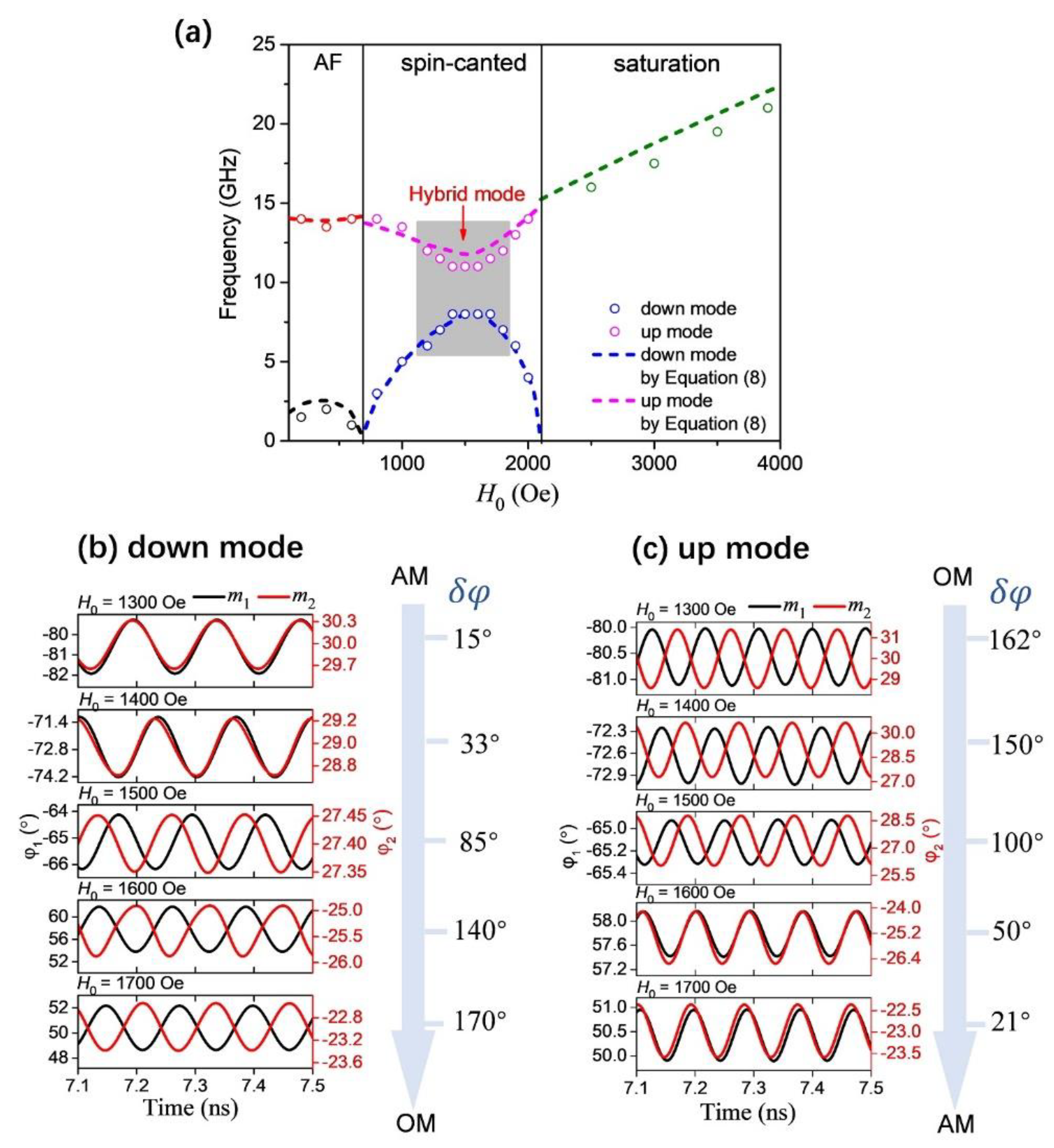
3.2. Dynamic Resonance Properties of Asymmetrical SAF

So far, we have investigated the magnon modes in symmetrical SAF with d1 = d2, and the magnon-magnon coupling does not occur due to symmetry-protection [9]. It has been theoretically predicted that the symmetry breaking will lead to a magnon-magnon coupling between the pure AM and OM, accompanied by an anti-crossing gap opening in frequency spectra [33]. This can be done in SAF structures by changing the two FM layers either with different materials or different thicknesses. To verify whether the intrinsic asymmetry can induce the coupling between the AM and OM, we simulated an asymmetrical SAF with different thicknesses, d1 = 2 nm for the bottom layer and d2 = 4 nm for the top layer. All other conditions are the same as the symmetrical SAF. The external bias field is applied along the x-direction.
Figure 4a shows the simulated dispersion relation of the asymmetrical SAF. An obvious anti-crossing gap is observed in the spin-canted region, indicating the magnon-magnon coupling phenomena appears. Here we define the magnon coupling strength as g = ( f up f down ) / 2 , where fup and fdown refer to the minimum frequency of up branch and the maximum frequency of down branch. The simulation shows that the magnon-magnon coupling strength is   g = 1.5 GHz in our sample. Theoretically, the resonance frequency can also be derived from the eigenvalue equation of Equation (4) [33]:
ω 4 ( a 2 + c 2 b ) ω 2 + 2 b + c 4 b 2 ( 1 a 2 ) ( a 2 + c 1 ) = 0
where a = H 0 H c r i , 2 ,   b = 2 | J I E C | μ 0 M s 2 ( d 1 + d 2 ) , and c = 1 ( d 1 d 2 d 1 + d 2 ) 2 . Thus, the angular frequency of the up and down branches can be obtained as:
ω up , down = 1 2 ( a 2 + c 2 b ) ± b 2 + 2 b + c b [ a 2 ( 2 b + c ) ( 2 c ) b c 2 ( b 2 + 2 b + c ) ] 2 + ( 1 c ) ( 2 b + c ) 3 4 ( b 2 + 2 b + c ) 2
The theoretical curves calculated from Equation (8) are depicted by dash lines in Figure 4a in the spin-canted region.
To acquire a clearer insight into the behavior of magnon-magnon coupling, we further studied the phase difference of magnetization evolution between m 1 and m 2 , as shown in Figure 4b,c. The down mode and up mode have obvious changes with the external magnetic field. As the external magnetic field H0 increases, the down mode changes from pure AM to OM, while the up mode changes from pure OM to AM. Remarkably, the phase difference of the new hybrid mode is not 0 °   or 180 °   but almost 90 ° at the strongest coupling field (H0 = 1500 Oe). Actually, this process of change can also establish the relationship between the phase difference and the magnon coupling strength.
So far, we have investigated the magnon–magnon coupling in symmetrical SAF with d1 = d2 and asymmetrical SAF with d 1 d 2 . For symmetrical SAF, only pure in-phase AM and out-of-phase OM are observed and the phase difference δ φ = φ 1 φ 2 between m 1 and m 2 is constant ( δ φ = 0 ° for the AM and 180 ° for the OM magnons), as shown in Figure 5a. For the asymmetrical SAF, as shown in Figure 5b, the phase difference δ φ varies with the external magnetic field H0, showing the δ φ changes from 0 ° to 180 ° for the down magnon mode while changes from 180 ° to 0 ° for the up mode. An obvious hybrid characteristic is shown.

4. Conclusions

In summary, we have investigated the coupling between acoustic and optic magnon modes in both symmetrical and asymmetrical SAFs. In addition to the frequency dispersion, here we pay more attention to the phase difference between the sublayer magnetizations for these two SAF systems. For the symmetrical SAF, the in-phase AM and out-of-phase OM exist separately and their magnetic field-dependent frequency branches cross each other at a degenerate point, and no magnon-magnon coupling occurs. In contrast, for an asymmetrical SAF, however, an obvious anti-crossing gap appears in frequency dispersion relations and the magnon-magnon coupling between the AM and OM occurs due to the intrinsic symmetry breaking of the system. The original AM and OM magnons gradually hybridizes with the increase of the coupling strength. The phase difference between m 1 and m 2 is almost 90 ° at the strongest coupling field. The study demonstrates a clear physical picture of the mode coupling, from which a hybrid spin-wave mode can be generated by turning the two distinct modes into resonance and the physical properties of the coupled modes have changed significantly. In addition, generating the hybrid spin-wave states may also provide assistance in the development of future magnonic devices.

Author Contributions

Conceptualization, X.C. and Y.L.; data curation, C.Z. and S.Z.; formal analysis, X.C., Y.L. and Z.Z.; writing—original draft preparation, X.C.; writing—review and editing, Y.L. and Z.Z. All authors have read and agreed to the published version of the manuscript.

Funding

This work is supported by the National Key Research and Development Project of China (2018YFB0407603) and the National Natural Science Foundation of China (Grant Nos. 11774260, 51971161, 11874120, 52171230).

Institutional Review Board Statement

Not applicable.

Informed Consent Statement

Not applicable.

Data Availability Statement

The study did not report any data.

Conflicts of Interest

The authors declare no conflict of interest. The funders had no role in the design of the study; in the collection, analyses, or interpretation of data; in the writing of the manuscript, or in the decision to publish the results.

References

  1. Chumak, A.V.; Vasyuchka, V.I.; Serga, A.A.; Hillebrands, B. Magnon spintronics. Nat. Phys. 2015, 11, 453. [Google Scholar] [CrossRef]
  2. Yu, H.; Xiao, J.; Schultheiss, H. Magnetic texture based magnonics. Phys. Rep. 2021, 905, 1. [Google Scholar] [CrossRef]
  3. Cheng, R.; Xiao, J.; Niu, Q.; Brataas, A. Spin Pumping and Spin-Transfer Torques in Antiferromagnets. Phys. Rev. Lett. 2014, 113, 057601. [Google Scholar] [CrossRef] [PubMed] [Green Version]
  4. Baltz, V.; Manchon, A.; Tsoi, M.; Moriyama, T.; Ono, T.; Tserkovnyak, Y. Antiferromagnetic spintronics. Rev. Mod. Phys. 2018, 90, 015005. [Google Scholar] [CrossRef] [Green Version]
  5. Rezende, S.M.; Azevedo, A.; Rodríguez-Suárez, R.L. Introduction to antiferromagnetic magnons. J. Appl. Phys. 2019, 126, 151101. [Google Scholar] [CrossRef] [Green Version]
  6. Cheng, R.; Xiao, D.; Brataas, A. Terahertz Antiferromagnetic Spin Hall Nano-Oscillator. Phys. Rev. Lett. 2016, 116, 207603. [Google Scholar] [CrossRef]
  7. Vaidya, P.; Morley, S.A.; van Tol, J.; Liu, Y.; Cheng, R.; Brataas, A.; Lederman, D.; del Barco, E. Subterahertz spin pumping from an insulating antiferromagnet. Science 2020, 368, 160. [Google Scholar] [CrossRef] [Green Version]
  8. Li, J.; Wilson, C.B.; Cheng, R.; Lohmann, M.; Kavand, M.; Yuan, W.; Aldosary, M.; Agladze, N.; Wei, P.; Sherwin, M.S.; et al. Spin current from sub-terahertz-generated antiferromagnetic magnons. Nature 2020, 578, 70. [Google Scholar] [CrossRef]
  9. MacNeill, D.; Hou, J.T.; Klein, D.R.; Zhang, P.; Jarillo-Herrero, P.; Liu, L. Gigahertz Frequency Antiferromagnetic Resonance and Strong Magnon-Magnon Coupling in the Layered Crystal CrCl3. Phys. Rev. Lett. 2019, 123, 047204. [Google Scholar] [CrossRef] [Green Version]
  10. Sklenar, J.; Zhang, W. Self-Hybridization and Tunable Magnon-Magnon Coupling in van der Waals Synthetic Magnets. Phys. Rev. Appl. 2021, 15, 044008. [Google Scholar] [CrossRef]
  11. Liensberger, L.; Kamra, A.; Maier-Flaig, H.; Geprags, S.; Erb, A.; Goennenwein, S.T.B.; Gross, R.; Belzig, W.; Huebl, H.; Weiler, M. Exchange-Enhanced Ultrastrong Magnon-Magnon Coupling in a Compensated Ferrimagnet. Phys. Rev. Lett. 2019, 123, 117204. [Google Scholar] [CrossRef] [Green Version]
  12. Li, Y.; Cao, W.; Amin, V.P.; Zhang, Z.; Gibbons, J.; Sklenar, J.; Pearson, J.; Haney, P.M.; Stiles, M.D.; Bailey, W.E.; et al. Coherent Spin Pumping in a Strongly Coupled Magnon-Magnon Hybrid System. Phys. Rev. Lett. 2020, 124, 117202. [Google Scholar] [CrossRef] [Green Version]
  13. Chen, J.; Liu, C.; Liu, T.; Xiao, Y.; Xia, K.; Bauer, G.E.W.; Wu, M.; Yu, H. Strong Interlayer Magnon-Magnon Coupling in Magnetic Metal-Insulator Hybrid Nanostructures. Phys. Rev. Lett. 2018, 120, 217202. [Google Scholar] [CrossRef] [Green Version]
  14. Parkin, S.S.P.; More, N.; Roche, K.P. Oscillations in exchange coupling and magnetoresistance in metallic superlattice structures: Co/Ru, Co/Cr, and Fe/Cr. Phys. Rev. Lett. 1990, 64, 2304. [Google Scholar] [CrossRef]
  15. Grunberg, P.; Schreiber, R.; Pang, Y.; Brodsky, M.B.; Sowers, H. Layered magnetic structures: Evidence for antiferromagnetic coupling of Fe layers across Cr interlayers. Phys. Rev. Lett. 1986, 57, 2442. [Google Scholar] [CrossRef]
  16. Ruderman, M.A.; Kittel, C. Indirect Exchange Coupling of Nuclear Magnetic Moments by Conduction Electrons. Phys. Rev. 1954, 96, 99. [Google Scholar] [CrossRef]
  17. Kasuya, T. A Theory of Metallic Ferro- and Antiferromagnetism on Zener’s Model. Prog. Theor. Phys. 1956, 16, 45. [Google Scholar] [CrossRef]
  18. Zhang, Z.; Zhou, L.; Wigen, P.E.; Ounadjela, K. Angular dependence of ferromagnetic resonance in exchange-coupled Co/Ru/Co trilayer structures. Phys. Rev. B 1994, 50, 6094. [Google Scholar] [CrossRef] [PubMed]
  19. Rezende, S.M.; Chesman, C.; Lucena, M.A.; Azevedo, A.; de Aguiar, F.M.; Parkin, S.S.P. Studies of coupled metallic magnetic thin-film trilayers. J. Appl. Phys. 1998, 84, 958. [Google Scholar] [CrossRef]
  20. Belmeguenai, M.; Martin, T.; Woltersdorf, G.; Maier, M.; Bayreuther, G. Frequency- and time-domain investigation of the dynamic properties of interlayer-exchange-coupled Ni81Fe19/Ru/Ni81Fe19 thin films. Phys. Rev. B 2007, 76, 104414. [Google Scholar] [CrossRef] [Green Version]
  21. Waring, H.J.; Johansson, N.A.B.; Vera-Marun, I.J.; Thomson, T. Zero-field Optic Mode Beyond 20 GHz in a Synthetic Antiferromagnet. Phys. Rev. Appl. 2020, 13, 034035. [Google Scholar] [CrossRef] [Green Version]
  22. Sud, A.; Zollitsch, C.W.; Kamimaki, A.; Dion, T.; Khan, S.; Iihama, S.; Mizukami, S.; Kurebayashi, H. Tunable magnon-magnon coupling in synthetic antiferromagnets. Phys. Rev. B 2020, 102, 100403. [Google Scholar] [CrossRef]
  23. Dai, C.; Ma, F. Strong magnon–magnon coupling in synthetic antiferromagnets. Appl. Phys. Lett. 2021, 118, 112405. [Google Scholar] [CrossRef]
  24. Shiota, Y.; Taniguchi, T.; Ishibashi, M.; Moriyama, T.; Ono, T. Tunable Magnon-Magnon Coupling Mediated by Dynamic Dipolar Interaction in Synthetic Antiferromagnets. Phys. Rev. Lett. 2020, 125, 017203. [Google Scholar] [CrossRef] [PubMed]
  25. He, W.; Xie, Z.K.; Sun, R.; Yang, M.; Li, Y.; Zhao, X.-T.; Liu, W.; Zhang, Z.D.; Cai, J.-W.; Cheng, Z.-H.; et al. Anisotropic Magnon–Magnon Coupling in Synthetic Antiferromagnets. Chin. Phys. Lett. 2021, 38, 057502. [Google Scholar] [CrossRef]
  26. Donahue, M.J.; Porter, D.G. OOMMF User’s Guide; Interagency Report NISTIR 6376; NIST: Gaithersburg, MD, USA, 1999. Available online: http://math.nist.gov/oommf (accessed on 10 October 2021).
  27. Kanai, S.; Yamanouchi, M.; Ikeda, S.; Nakatani, Y.; Matsukura, F.; Ohno, H. Electric field-induced magnetization reversal in a perpendicular-anisotropy CoFeB-MgO magnetic tunnel junction. Appl. Phys. Lett. 2012, 101, 122403. [Google Scholar] [CrossRef]
  28. Devolder, T.; Bianchini, L.; Miura, K.; Ito, K.; Kim, J.-V.; Crozat, P.; Morin, V.; Helmer, A.; Chappert, C.; Ikeda, S.; et al. Spin-torque switching window, thermal stability, and material parameters of MgO tunnel junctions. Appl. Phys. Lett. 2011, 98, 162502. [Google Scholar] [CrossRef] [Green Version]
  29. Sorokin, S.; Gallardo, R.A.; Fowley, C.; Lenz, K.; Titova, A.; Atcheson, G.Y.P.; Dennehy, G.; Rode, K.; Fassbender, J.; Lindner, J.; et al. Magnetization dynamics in synthetic antiferromagnets: Role of dynamical energy and mutual spin pumping. Phys. Rev. B 2020, 101, 144410. [Google Scholar] [CrossRef]
  30. Kittel, C. On the Theory of Ferromagnetic Resonance Absorption. Phys. Rev. 1948, 73, 155. [Google Scholar] [CrossRef]
  31. Chen, X.; Zheng, C.; Zhang, Y.; Zhou, S.; Liu, Y.; Zhang, Z. Identification and manipulation of spin wave polarizations in perpendicularly magnetized synthetic antiferromagnets. New J. Phys. 2021, 23, 113029. [Google Scholar] [CrossRef]
  32. Chen, X.; Zheng, C.; Zhou, S.; Liu, Y.; Zhang, Z. Ferromagnetic resonance modes of a synthetic antiferromagnet at low magnetic fields. J. Phys. Condens. Matt. 2021, 34, 015802. [Google Scholar] [CrossRef]
  33. Li, M.; Lu, J.; He, W. Symmetry breaking induced magnon-magnon coupling in synthetic antiferromagnets. Phys. Rev. B 2021, 103, 064429. [Google Scholar] [CrossRef]
Figure 1. In-plane hysteresis loop as a function of the external field H0 along x-direction for a symmetrical SAF (Sample-I) (a) and asymmetrical SAF (Sample-II) (b), respectively. The corresponding equilibrium angles of the magnetization vectors of two FM layers for the symmetrical SAF (c) and asymmetrical SAF (d) are also shown.
Magnetochemistry 08 00007 g001
Figure 2. Top panel: The simulated AFMR response signal for the transverse pumping (a) and longitudinal pumping (b) at H0 = 600 Oe. An acoustic resonance mode (AM) occurs at low frequency f = 4 GHz while the optic resonance mode (OM) occurs at f = 15 GHz. The color-coding refers to the resonance amplitude of magnetization response. The insert diagram shows the corresponding diagram of magnetization precession, where m1(m2) represents the magnetization unit vector for ferromagnetic layer 1(2). Bottom panel: The magnetization oscillations of m1 (black) and m2 (red) in the acoustic mode (c) and optic mode (e), where my and mz precess in phase in the acoustic mode while out of phase in the optic mode. The corresponding net magnetization m = (m1 + m2)/2 oscillations are also shown in (d) for AM and (f) for OM.
Magnetochemistry 08 00007 g002
Figure 3. (a) Dispersion relation of frequency versus external magnetic field H0 for the symmetrical SAF (Sample-I). The open circles represent the simulation results and dash lines represent the analytical calculations; (b,c) Comparison of the phase difference for the AM and OM resonant states at three different fields. Here φ i   ( i = 1 ,   2 ) is the azimuth angle of m i . It clearly shows the time-dependent in-phase precessions for the AM and antiphase precessions for the OM resonance state.
Magnetochemistry 08 00007 g003
Figure 4. (a) Dispersion relation of frequency in asymmetrical SAF (Sample-II) with the external magnetic field H0 applied along the x-axis direction. The open circles represent the simulation results while dotted lines represent the corresponding theoretical calculations, showing an obvious coupling gap. Phase difference of down mode (b) and up mode (c) at 1300 Oe, 1400 Oe,1500 Oe, 1600 Oe, and 1700 Oe. The phase difference between m1 and m2 varies with the external magnetic field, indicating a new hybrid mode.
Magnetochemistry 08 00007 g004
Figure 5. (a) Phase difference of pure AM (black curve) and pure OM (red curve) for the symmetrical SAF (Sample-I); (b) Phase difference of down branch mode (red curve) and up branch mode (black curve) for the asymmetrical SAF (Sample-II).
Magnetochemistry 08 00007 g005
Publisher’s Note: MDPI stays neutral with regard to jurisdictional claims in published maps and institutional affiliations.

