Article

Thin Liquid Film Dynamics on a Spinning Spheroid

1
Department of Mechanical Engineering, University of Canterbury, Christchurch 8041, New Zealand
2
Laboratory of Fluid Mechanics and Instabilities, EPFL, 1015 Lausanne, Switzerland
*
Author to whom correspondence should be addressed.
Fluids 2021, 6(9), 318; https://doi.org/10.3390/fluids6090318
Submission received: 22 July 2021 / Revised: 30 August 2021 / Accepted: 31 August 2021 / Published: 6 September 2021
(This article belongs to the Special Issue Thin Liquid Films: From Theory to Applications)

Abstract

:
The present work explores the impact of rotation on the dynamics of a thin liquid layer deposited on a spheroid (bi-axial ellipsoid) rotating around its vertical axis. An evolution equation based on the lubrication approximation was derived, which takes into account the combined effects of the non-uniform curvature, capillarity, gravity, and rotation. This approximate model was solved numerically, and the results were compared favorably with solutions of the full Navier–Stokes equations. A key advantage of the lubrication approximation is the solution time, which was shown to be at least one order of magnitude shorter than for the full Navier–Stokes equations, revealing the prospect of controlling film dynamics for coating applications. The thin film dynamics were investigated for a wide range of geometric, kinematic, and material parameters. The model showed that, in contrast to the purely gravity-driven case, in which the fluid drains downwards and accumulates at the south pole, rotation leads to a migration of the maximum film thickness towards the equator, where the centrifugal force is the strongest.

1. Introduction

Spin coating is a process which is routinely used in the microfabrication of multiple devices, including printed circuit boards, displays, solar cells, or microfluidic devices. It consists of depositing fluid on a surface and rotating it, exploiting the centrifugal force to distribute the fluid uniformly on the surface. Over the years, the process of spin coating has been optimized for flat, rigid surfaces, and much is currently understood about spin coating such surfaces. See [1] for a recent review of the process and its current understanding. Applying the spin coating technique to a curved surface is, however, ineffective because it leads to a non-uniform film thickness [2,3,4,5], which is typically an undesired outcome. The present study aims to broaden the current understanding of the dynamics of a thin liquid film subjected to rotation on a non-flat surface through mathematical modeling and numerical simulations. Building on what is already known concerning the evolution of a thin liquid film on a rotating cylinder [6,7,8], a stationary [9,10,11,12,13] and a rotating sphere [14,15], in this study we consider the fluid dynamics of a liquid layer on a rotating spheroid as a natural extension of the spherical and cylindrical cases with two distinct principal radii of curvature.
In order to describe the evolution of thin liquid films on complex-shaped substrates, the governing equations must first be expressed in a “body-fitted” coordinate system. The pioneering work of Schwartz and Weidner in [16] to formulate the lubrication approximation governing the leading order dynamics of a thin liquid film on a curved substrate was later extended, generalized, and formalized in [17,18,19,20]. This general framework was elegantly applied in [21] to shed light on the dynamics of droplets on virtual leaf surfaces. Inducing rotation to the curved substrate, Weidner derived through scaling arguments and perturbation methods of the lubrication approximation for the flow of a thin liquid film on a spinning, arbitrarily curved, axisymmetric surface [22,23] and applied it to spin coat the interior of metal beverage cans.
Most of the aforementioned studies either investigated the effects of a complex substrate shape or those of rotation. References [22,23] are, to the best of our knowledge, the only studies which combined an arbitrary substrate shape with rotation. The present study builds on the work of Roy et al. [17], who derived a comprehensive model which accurately includes the effect of the substrate curvature via a physical multiple-scale approach. Accordingly, we derive an extended lubrication model, implement it numerically, and examine its accuracy via comparison with the full Navier–Stokes equations. Thereafter, the effects of a large set of parameters on the dynamics of a thin film on a spinning spheroid are investigated. Therefore, the present work presents, for the first time, a systematic approach, both confirming the validity of the lubrication model and capturing the combined effects of non-constant curvature and centrifugal force.
This paper is organized as follows: Section 2 describes how this comprehensive framework is applied to a spheroid subjected to rotation. Section 3 describes the solution methodology adopted to solve the highly nonlinear set of partial differential equations, and the corresponding validation. The parametric investigation is then presented and discussed in Section 4. Lastly, the conclusions are summarized in Section 5.

2. The Lubrication Model

We consider a thin liquid film on the outer surface of a spheroid (bi-axial ellipsoid), whose horizontal and vertical semi-axes are denoted by a and c, respectively. The liquid is assumed to be incompressible and Newtonian, characterized by its density ρ , surface tension σ , and dynamic viscosity μ . In addition to gravitational, viscous, and capillary forces, the system is also subjected to rotation around the vertical axis, at a constant angular velocity Ω . A sketch of the problem is shown in Figure 1.
The characteristic length scales are h 0 and L and denote, respectively, the film thickness and a measure of the substrate (either a radius of curvature or the length scale over which the film thickness varies). In what follows, in order to study the flow dynamics in the framework of the lubrication theory, both the film parameter δ = h 0 / L and the Reynolds number are assumed to be small.

2.1. Generic Equation

We start by recalling the dimensionless lubrication model formulated by Roy, Roberts, and Simpson (RRS) [17]. The substrate is parameterized by x = ( x 1 , x 2 ) on Cartesian coordinates, such that x 1 ( x , y , z ) and x 2 ( x , y , z ) are the principal directions (i.e., directions of principal curvature of the substrate). Accordingly, together with the film thickness h ( x , t ) , the curvilinear coordinate system ( x 1 , x 2 , h ) forms an orthogonal basis, and the free surface F s is defined by
F s ( x , t ) = S ( x ) + δ h ( x , t ) n ( x ) ,
where S ( x ) specifies the surface of the substrate and n ( x ) represents the unit normal vector to S ( x ) . The RRS model for the film thickness h ( x , t ) is then given as
b t + δ 3 · [ h 2 b κ ˜ δ h 4 A 1 · ( κ 1 + κ 2 ) ] + B o · [ h 3 g δ h 4 A 2 · g + δ g n h 3 h ] = 0 ,
where the Bond number B o corresponds to
B o = ρ g h 0 2 σ .
The matrices A 1 and A 2 are linked to the substrate curvature tensor and defined as
A 1 = 1 2 κ 2 0 0 κ 1 , A 2 = 3 2 κ 1 + κ 2 0 0 3 2 κ 2 + κ 1 ,
where κ 1 and κ 2 are the principal curvatures. The tangential and the normal components of the gravitational vector are represented by g = ( g x 1 , g x 2 ) T and g n , respectively. The term b ( x , t ) , which arises due to mass conservation, reads
b = h δ h 2 κ 1 + κ 2 2 + δ 2 h 3 κ 1 κ 2 3 ,
and is proportional to the volume of fluid that covers the corresponding infinitesimal area on the substrate S ( x ) . The free surface curvature κ ˜ is given by the following approximation:
κ ˜ = δ 2 h + κ 1 1 δ κ 1 h + κ 2 1 δ κ 2 h .
As noted in [17], although κ ˜ can also be approximated as
κ ˜ = δ 2 h + ( κ 1 + κ 2 ) + δ ( κ 1 2 + κ 2 2 ) ,
Equation (2e) is preferred, as it improves the validity and consistency of the model for thicker films and/or substrates of large curvature (small radius of curvature).

2.2. Lubrication Model for the Spheroid

In this study we assume that the flow is axisymmetric, thereby precluding the possible development of azimuthal instabilities, as reported in [9,11,12]. To investigate our problem of interest, the generic model (2) is applied to a thin film coating the outer surface of a spheroid. It is then extended to reflect the effect of rotation and also modified to allow for a time-dependent viscosity, so as to model polymer curing, as was done in [24], for instance. We summarize the derivation steps in the following.
First, spherical polar coordinates are employed on Cartesian coordinates
x = a cos φ sin θ , y = a sin φ sin θ , z = c cos θ ,
to parameterize and to construct the orthogonal basis. The location and the form of the substrate are determined by the specific ( x 1 , x 2 ) = ( θ , φ ) parameterization. The corresponding film equation is formulated by expressing the differential operators via the dimensionless metric coefficients m 1 and m 2 . The reader may refer to Bourne and Kendall [25] for the general formulations in curvilinear coordinates. Accordingly, the dimensionless metric coefficients with respect to the the parameterization defined above are derived as
m 1 = 1 + γ 2 2 + 1 γ 2 2 cos ( 2 θ ) , m 2 = sin θ ,
where the dimensionless constant
γ = c a
is the ratio of the vertical to horizontal semi-axes, and is hereafter referred to as the geometric parameter. The geometric parameter corresponds to three types of spheroids—namely, an oblate spheroid for γ < 1 , a sphere for γ = 1 , and a prolate spheroid for γ > 1 (see Figure 2). The principal curvatures κ 1 and κ 2 are expressed by the geometric parameter and the metric coefficients:
κ 1 = γ m 1 3 , κ 2 = γ m 1 .
The film parameter is chosen as
δ = h 0 a 1 .
We note that any choice of the film parameter is valid, as long as the radius of curvature is large enough compared to the characteristic film thickness at every point on the substrate. In other words, the film parameter might be replaced by another one, e.g., δ = h 0 / c , if h 0 c , and this would only require calibration of the related dimensionless parameters. Lastly, the gravitational terms are given by
g θ = γ sin θ m 1 , g n = cos θ m 1 ,
in the polar and normal directions, respectively.
Next, Equation (2) is adapted by introducing a time-dependent viscosity μ ( t ) = μ 0 μ h ( t ) , and the body force terms that emerge due to the centrifugal force are incorporated. Finally, the dimensionless lubrication model for the axisymmetric flow of a thin film, deposited on the outer surface of a spheroid rotating around its vertical axis, is given in compact form as
R 0 h t + R 1 h + R 2 h + R 3 h + R 4 = 0 ,
where h ( θ , t ) is the dimensionless film thickness and the primes denote the derivatives with respect to the polar angle θ . The functions R i ( i = 0 4 ) are determined by several auxiliary functions and dimensionless parameters as follows:
R 0 ( θ , t ) = 1 s 1 μ h ( t ) b 0 ,
R 1 ( θ , t ) = δ 3 s 2 f n + δ k 2 + ( s 1 s 2 ) b h δ h 3 ,
R 2 ( θ , t ) = δ 3 s 2 ( 2 s 2 s 1 + s 1 s 2 ) b h h 3 ,
R 3 ( θ , t ) = δ 3 s 2 2 s 1 b h h 3 ,
R 4 ( θ , t ) = m 2 f θ b f h 3 δ 4 2 s 2 d 1 k 1 κ 2 h 4 + δ 3 s 2 ( k 1 + k 2 δ h ) h 3 ,
where
b 0 = 1 + 2 a 1 h + 3 a 2 h 2 , b h = 1 + a 1 h + a 2 h 2 ,
a 1 = δ 2 ( κ 1 + κ 2 ) , a 2 = δ 2 3 κ 1 κ 2 ,
s 1 = 1 m 1 m 2 , s 2 = m 2 m 1 ,
b f = 1 δ 3 2 κ 1 + κ 2 h ,
k 1 = κ 1 + κ 2 , k 2 = κ 1 2 + κ 2 2 .
The gravitational and centrifugal forces are combined into an extended body force term f = ( f θ , f n ) of polar and normal components
f θ = B o γ sin θ m 1 + Ω d 2 sin θ cos θ m 1 ,
f n = B o cos θ m 1 + γ Ω d 2 sin 2 θ m 1 ,
where the dimensionless angular velocity is
Ω d = Ω ρ a h 0 2 σ .
The time-dependent viscosity μ ( t ) = μ 0 μ h ( t ) allows us to model polymer curing, and is chosen as the same piecewise function employed by Lee et al. [24] given in dimensionless form as
μ h ( t ) = exp ( t β m ) 0 t t s , exp ( t s β m ) ( t / t s ) α t s t ,
where β m = β t m is the dimensionless curing coefficient, α is the viscosity curing power, and t s = t c / t m is the dimensionless curing time. The constant viscosity case μ ( t ) = μ 0 can simply be recovered by setting the time-dependent function to unity ( μ h ( t ) = 1 ).
Equation (5), which governs the film dynamics on the rotating spheroid, is a key contribution and the focus of this study. Note that it has been constructed explicitly by the dimensionless metric coefficients ( m 1 , m 2 ) and the dimensionless parameters ( δ , γ , Ω d , B o ). The present form can be tailored to other axisymmetric substrates, simply by introducing a relevant parameterization of the substrate, and adjusting the metric coefficients and other dimensionless parameters. Accordingly, the evolution Equation (5) can be considered as a 1D generic model applicable to substrates of diverse shapes with arbitrary external forces.
At this point, some additional comments are in order:
  • Equation (5) can be reduced to the model of a thin liquid film on a sphere of radius r s . Setting a = c = r s , we recover the evolution equation governing the dynamics of a thin film on a rotating sphere derived in [14,15] using a different approach.
    For small deviations from a sphere, i.e., for semi-axes satisfying ϵ = | a c | 1 , the equation at leading order in ϵ is also identical to the one derived for the spherical geometry. Nonetheless, depending on the choice of all the physical parameters together with the choice of the film parameter (which is also assumed to be small), the equation at the leading order might not reflect the actual dynamics, since ϵ is not the only small parameter of the problem. Therefore, the upcoming numerical investigations were all performed using the non-reduced version, even for ϵ = | a c | 1 .
  • For the non-rotating case, it is straightforward that Equation (5) does not admit any constant solution (such as h = 1 , which would indicate a uniform film thickness), unless the function R 4 is a constant. For substrates of uniform curvature, this function reduces to R 4 = m 2 f θ b f h 3 , which implies the possibility of a uniform coating for the zero gravity case ( f θ = 0 ). On the other hand, for substrates of non-uniform curvature, it is not possible to develop a uniform film thickness, even in a zero gravity field.

3. Solution Methodology and Validation

In this section, the methodology used to solve the lubrication model (5) and the corresponding Navier–Stokes (NS) equations is briefly described. We present sample cases that incorporate the time-dependent viscosity, gravity, capillarity, and rotation, as illustrations that encompass the entire set of driving forces. We compare the results obtained with Equation (5) and with the full NS equations. Thus, the validity of the lubrication model is first established, before showing a detailed parametric investigation of the thin film dynamics in Section 4.

3.1. Solution Methodology

All calculations were performed with the Finite Element software COMSOL Multiphysics (v. 5.5). The lubrication model (5) was implemented using the Coefficient Form PDE module, and the full NS equations were solved using the laminar two-phase flow module with a moving mesh in the liquid phase. The lubrication model was solved in the domain θ = [ 0 , π ] , where the number of elements in the mesh varied between 401 and 1601. The boundary condition was set to h θ = 0 for θ = { 0 , π } .
We emphasize that the lubrication model is a one-dimensional model (single spatial coordinate θ ) for one dependent variable (single unknown h), whereas the full NS equations constitute a two-dimensional problem (two spatial coordinates r and z) for three dependent variables (pressure and two velocity components) and must be solved in a deforming domain, resulting in much greater computational effort.

3.2. Validation

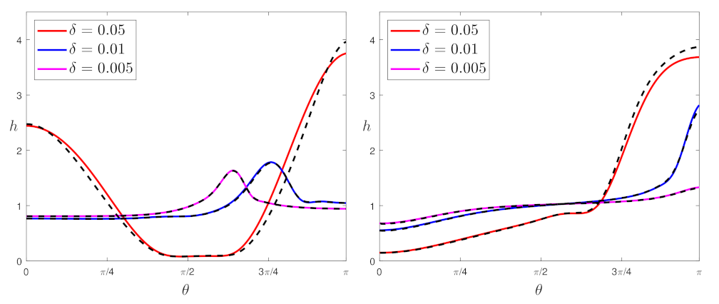
In this section, several cases are presented to confirm the consistency of the results obtained with the lubrication model (5) and the full NS equations. In accordance with Lee et al. [24], we set the physical parameters for VPS-32 as follows: initial film thickness h 0 = 0.1 mm, density ρ = 1160 kg/m 3 , dynamic viscosity parameters μ 0 = 7.1 kg/m.s, t c = 574 s, α = 5.3 , β = 2.06 × 10 3 s, acceleration of gravity g = 9.81 m/s 2 , surface tension σ = 0.02 N/m, and angular velocity Ω = 20 rad/s. While the Bond number was fixed ( B o = 0.0057 ) for the physical parameters given above, the geometric parameter was varied to consider both oblate and prolate spheroids, for γ = 0.5 and γ = 2 , respectively. Likewise, the film parameter was varied by considering different sizes of the horizontal semi-axis ( a = 0.1 m, 0.02 m, and 0.01 m) to determine a threshold value δ c of the film parameter, which ensured the accuracy of the model for δ δ c . Note that as δ and γ vary, the vertical semi-axis c and the dimensionless angular velocity Ω d also varied accordingly. Figure 3 displays the dimensionless film thickness profiles at t = 1150 s, where the solutions of the lubrication model (solid line) and the full NS equations (dashed line) are represented in dimensionless form simultaneously. The left panel of Figure 3 exhibits the steady thickness profiles on an oblate spheroid for γ = 0.5 , and the right panel represents the profiles on a prolate spheroid for γ = 2 . Three values of the film parameter are considered in each panel ( δ = 0.005 , 0.01 , and 0.05 ), to demonstrate that the lubrication model is in excellent agreement with the NS equations for δ 0.01 but visibly degrades for larger values of δ .
We underline that all simulations for the lubrication model were significantly faster than those for the full NS equations. For instance, the specific validation case presented in the left panel for δ = 0.005 was completed in 125 s (for 22478 degrees of freedom), whilst the lubrication model was solved in 8 s (for 1602 degrees of freedom). All numerical experiments were completed far more rapidly by utilizing the lubrication model.

4. Results and Discussion

After confirming the validity and efficiency of the lubrication model through particular cases, we perform a parametric study. The following analysis is carried out in dimensionless space, where the initial film thickness is fixed to unity h ( θ , t = 0 ) = 1 for every case, whereas the rest of the dimensionless parameters (geometric parameter γ , dimensionless angular velocity Ω d , and Bond number B o ) are systematically varied in order to investigate the relative impact of the acting forces.

4.1. Capillary Dominated Flow with Constant Viscosity

Prior to including all driving forces, we examine the flow driven purely by capillary effects. Therefore, we set the gravity and the angular velocity to zero, such that ( Ω d , B o ) = ( 0 , 0 ) and also assume a constant viscosity.
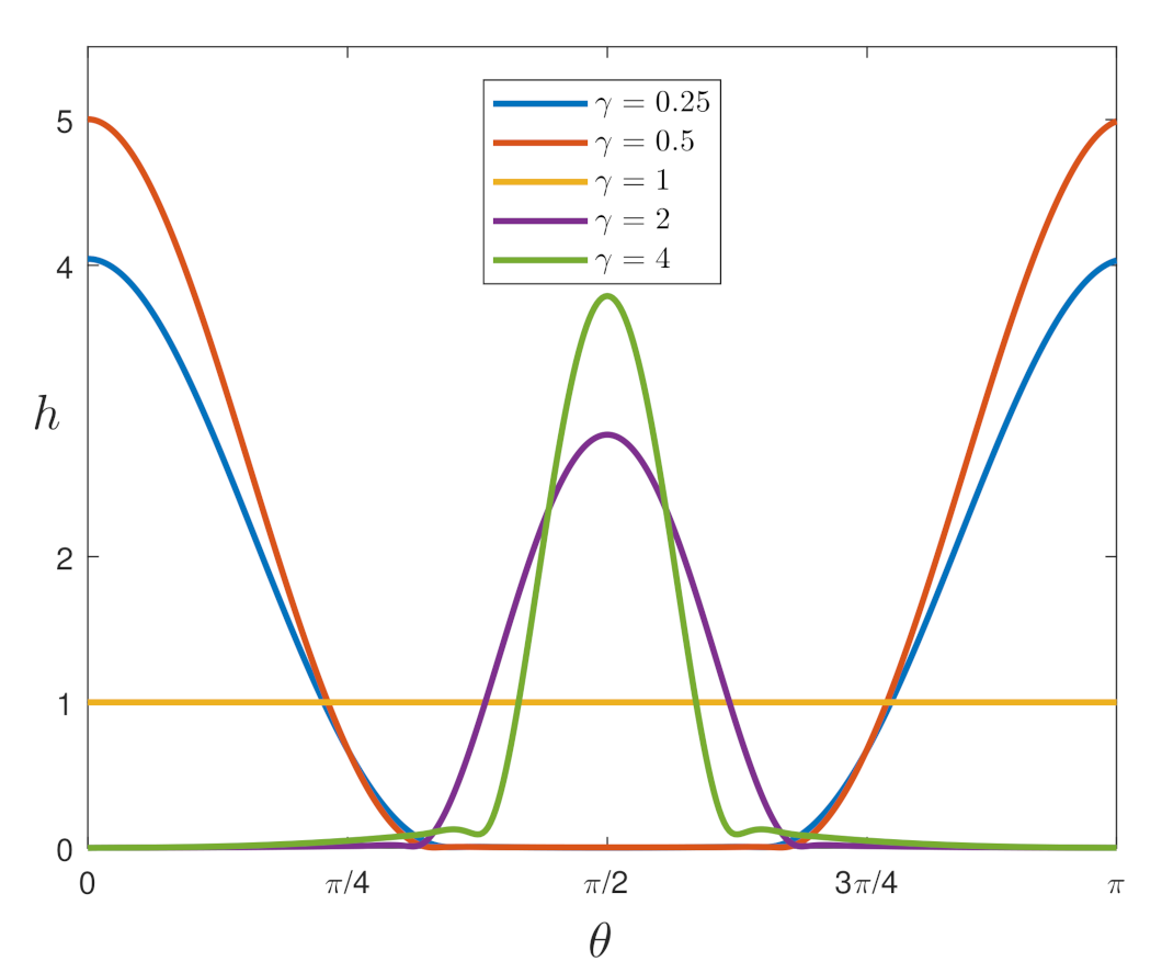
Figure 4 illustrates the film thickness profiles on oblate spheroids ( γ = 0.25 and 0.5 ), on a sphere ( γ = 1 ), and on prolate spheroids ( γ = 2 and 4). As expected, the film thickness remains constant and uniform in the particular case of a sphere, whereas for the all other cases, the fluid flows from regions of high curvature to those of low curvature: from the equator to the poles on oblate spheroids ( γ < 1 ) and from the poles to the equator on prolate spheroids ( γ > 1 ), which coincides with physical intuition. Note that although the minimum film thickness is non zero, it reaches values as low as 10 4 in the thinnest films. It is likely that Van der Waals forces should be taken into account to accurately represent the dynamics of such thin films, but modeling film wetting/dewetting is beyond the scope of this study.

4.2. Combined Effects of Substrate Shape, Capillarity, Gravity, and Rotation

Next, we carry out analysis for the complete set of dimensionless parameters ( γ , Ω d , B o ), where the film parameter is fixed to δ = 0.002 . First, the significance of the substrate shape is examined by setting the geometric parameter to γ = 0.5 , 1, and 2. Next, the impact of the angular velocity Ω d is tested, and alongside those results, the role of the centrifugal force on the film dynamics is discussed. Finally, the sensitivity of the film thickness distribution with respect to the Bond number sheds light on the effect of gravity relative to the capillary force.
Figure 5 represents the steady thickness profiles for B o = 0.0057 . The left panel of Figure 5 displays the non-rotating case Ω d = 0 , where the geometric parameter varies: γ = 0.5 , 1 , 2 . The results demonstrate the combined effect of curvature and gravity for different substrate shapes, and they differ significantly from those of the zero-gravity case (Section 4.1). While for γ = 1 the film simply tends to get thicker below the equator and thinner above, it behaves visibly differently for non-spherical spheroids. For γ = 2 (vertical semi-axis twice as large as the horizontal one), the thinning at the north pole and thickening at the south pole are more pronounced as the fluid accumulates around the south pole. Conversely, for γ = 0.5 , while the thickness does not vary much at the poles, a dip forms slightly above the equator and a bulge forms about θ = 2 π / 3 .
The right panel of Figure 5 shows the impact of the centrifugal force for Ω d = 0.1 , where the maximum film thickness migrates towards the equator, for all values of γ . The magnitude is largest for γ = 0.5 , which can be explained by the fact that the equator is farther away from the axis and the centrifugal forces is therefore stronger for γ = 0.5 than for γ = 1 and 2. For γ = 0.5 and γ = 1 , a steep hump and a relatively gradual one develops about the equator, respectively. For γ = 2 , the thickness is almost uniform in the region [ π / 3 , π ] . We conclude that the results coincide with physical intuition, and that the film thickness on a non-constant curvature substrate can be manipulated by the action of the centrifugal force. Likewise, the film response is clearly dependent on the geometric parameter γ .
After confirming that rotation around the vertical axis alters the thickness profiles, we investigate the impact of the angular velocity Ω d . Figure 6 shows the steady thickness profiles for B o = 0.0057 with variations of Ω d . The left panel of Figure 6 presents the results on a oblate spheroid for γ = 0.5 . We observe that the maximum thickness increases when increasing the dimensionless angular velocity for Ω d = 0 , 0.05 , 0.08 , and the location of the maximum film thickness is shifted towards the equator. The right panel of Figure 6 displays the thickness profiles on a prolate spheroid for γ = 2 , for Ω d = 0 , 0.1 and 0.2 . In the non-rotating case Ω d = 0 , the fluid accumulates at the south pole; for Ω = 0.1 an almost uniform profile forms in the region [ π / 4 , π ] , rather than a centered satellite. When imposing stronger rotation by setting Ω = 0.2 , the fluid moves away from both poles and accumulates about the equator, generating a relatively smooth hump.
Next, we report the comparative effect of the gravitational force against surface tension, by examining the deviations of the film thickness profiles via the Bond number. Figure 7 shows the steady thickness profiles for the fixed value of the dimensionless angular velocity Ω d = 0.03 , where the Bond number is set to B o = 5 × 10 4 , 10 3 and 5 × 10 3 . As the Bond number increases, the gravitational effect is more pronounced compared to surface tension. The left panel of Figure 7 illustrates the steady film thickness distribution for γ = 0.5 , and indicates that an almost symmetric steep hump emerges for relatively small Bond numbers, whereas symmetry is broken when the Bond number increases. On the contrary, for γ = 2 (right panel of Figure 7), rotation does not induce any hump formation about the equator for the investigated values of Ω d and B o . For both γ = 0.5 and γ = 2 , the thickness at the north and south poles increases with B o .
Lastly, we represent a typical temporal evolution of the film thickness in Figure 8. Profiles are shown for the dimensionless times t = 4.3 , 8.6 , and 21.5 , where in this case t = 21.5 represents the final steady state. The left panel of Figure 8 shows the evolution for an oblate spheroid rotating at Ω d = 0.08 , and the right panel shows the evolution for a prolate spheroid rotating at Ω d = 0.2 . In both cases, we observe a thickening at the equator and a thinning at the poles.

4.3. Minimum and Maximum Film Thickness

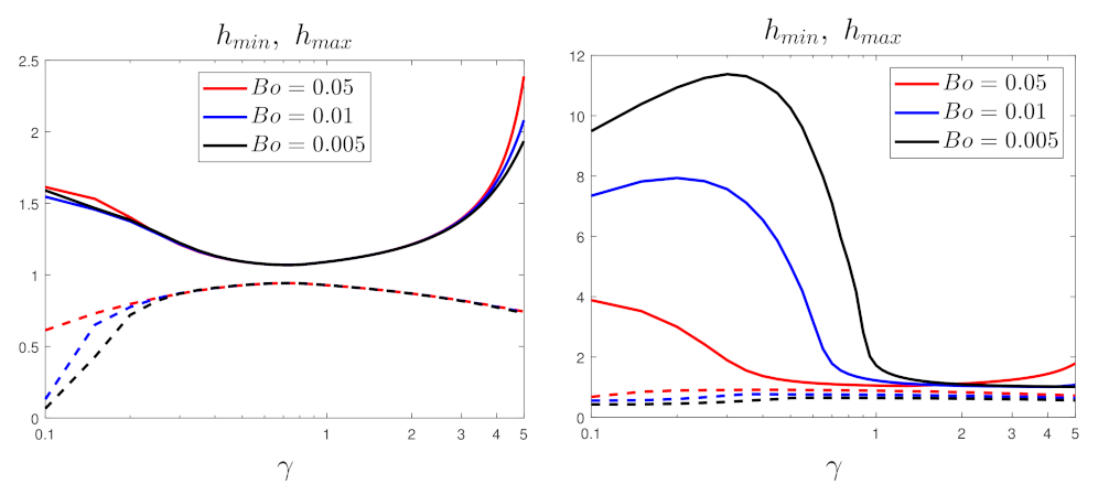
Following the analysis of the effects of dimensionless parameters on thickness profiles, we summarize the minimum and maximum values of the film thickness in terms of the geometric parameter γ and the dimensionless angular velocity Ω d , by setting three values of the Bond number B o = 0.05 , 0.01 , and 0.005 . Figure 9 displays the alterations of the maximum and minimum values of the steady film thickness, with respect to the geometric parameter. The left panel shows the results for the non-rotating case Ω d = 0 , and the right panel presents the rotating case with Ω d = 0.2 . It is obvious that the effect of B o is not substantial in the non-rotating case. Interestingly, the minimum and maximum thicknesses are closest to 1 when the geometric parameter γ is slightly smaller than 1. This can be ascribed to the finite value of B o , since, in the zero-gravity case, the film thickness remains uniform when γ is exactly equal to 1 (Section 4.1). Decreasing or increasing γ results in an increase in the maximum thickness and a decrease in the minimum thickness, for all values of B o . The right panel of Figure 9 shows that the maximum film thickness is strongly affected by the centrifugal force for oblate spheroids ( γ < 1 ), an effect that is more pronounced as the Bond number decreases. Conversely, this effect is small for prolate spheroids ( γ > 1 ). For all spheroids, the minimum thickness varies only slightly.
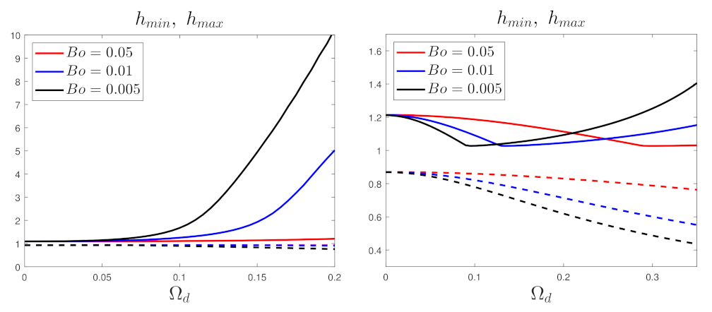
Next, we examine the effects of the centrifugal force on the maximum and minimum film thickness in Figure 10, for the same values of the Bond number, 0.05 , 0.01 , and 0.005 . The left panel of Figure 10 shows the variations on an oblate spheroid ( γ = 0.5 ). The maximum thickness increases dramatically for large values of Ω d and small values of the Bond number, B o = 0.01 and 0.05 , as the fluid tends to accumulate towards the equator and to form a steep bulge (see Figure 5, Figure 6 and Figure 7). For all cases, the minimum value does not exhibit a remarkable change. On the other hand, for the prolate spheroid ( γ = 2 ) shown in the right panel of Figure 10, the minimum thickness decreases monotonically with Ω d , as more fluid moves away from the north pole on prolate spheroids than on oblate spheroids (see, e.g., Figure 6). The maximum thickness decreases until reaching h m a x 1 for a critical value of Ω d , and continuously increases thereafter. This non-monotonic behaviour corresponds to a shift of the maximum thickness location from the south pole to the equator as Ω d increases (see Figure 6).
We note that although the variations in the minimum film thickness appear to be overlapping in some of the cases presented above, this is due to the marginal difference on the given scale and a consequence of the rapid solidification of the film, which did not let the film drain further.

4.4. Free Surface Profiles

Lastly, we present in Figure 11 two specific cases to demonstrate the free surface profiles qualitatively for a fixed Bond number B o = 0.0057 (for clarity, the film thickness has been magnified by 50). In the left panel of Figure 11, the free surface on an oblate spheroid for γ = 0.5 is represented with dashed and solid lines for Ω d = 0 and Ω d = 0.12 , respectively. We can see that, with rotation, the liquid is pushed from both poles towards the equator, and forms a bulge slightly below the equator. In the right panel of Figure 11, the free surface on a prolate spheroid for γ = 5 is represented with dashed and solid lines for Ω d = 0 and Ω d = 0.45 , respectively. In this case, rotation prevents droplet formation at the south pole, again by driving the fluid towards the equator.

5. Conclusions

In this article, we have examined the relative effects of various forces acting on a thin liquid film coating the outer surface of a spheroid subjected to rotation around the vertical axis. An evolution equation was derived based on the general framework proposed by Roy et al. [17]. The corresponding lubrication model was formulated via the dimensionless metric coefficients and includes a set of dimensionless parameters. The accuracy of the reduced model was verified by numerical simulations of the full NS equations, and the validity of the lubrication approximation was assessed with a range of film parameters. A parametric investigation was performed to scrutinize the significance of the substrate shape (geometric parameter γ ), the impact of the external forcing (dimensionless angular velocity Ω d ), and the relative strengths of gravity and surface tension (Bond number B o ). It was confirmed that rotation around the vertical axis can be used to manipulate the film thickness distribution, and that the film dynamics is highly sensitive to the substrate shape. The results of this study point to more necessary work, such as extending the film equation to the three-dimensional case, introducing a multi-directional forcing, and possibly generating the body force required to induce the desired coating distribution by applying suitable kinematics to the curved surface.

Author Contributions

M.S. and E.B. conceived, planned, and lead the research. S.D. developed the model and implemented it. All authors have read and agreed to the published version of the manuscript.

Funding

This work is part of the project “Development of a multi-axis spin-coating system to coat curved surfaces” funded by the New Zealand Ministry of Business, Innovation and Employment Endeavour fund (grant number UOCX1904). The funding is gratefully acknowledged.

Institutional Review Board Statement

Not applicable.

Informed Consent Statement

Not applicable.

Data Availability Statement

The data presented in this study are available on request from the corresponding author.

Conflicts of Interest

The authors declare no conflict of interest.

References

  1. Sahu, N.; Parija, B.; Panigrahi, S. Fundamental understanding and modeling of spin coating process: A review. Indian J. Phys. 2009, 83, 493–502. [Google Scholar] [CrossRef] [Green Version]
  2. Feng, X.G.; Sun, L.C. Mathematical model of spin-coated photoresist on a spherical substrate. Opt. Express 2005, 13, 7070–7075. [Google Scholar] [CrossRef] [PubMed]
  3. Chen, L.J.; Liang, Y.Y.; Luo, J.B.; Zhang, C.H.; Yang, G.G. Mathematical modeling and experimental study on photoresist whirl-coating in convex-surface laser lithography. J. Opt. A Pure Appl. Opt. 2009, 11, 105408. [Google Scholar] [CrossRef]
  4. Liu, H.; Fang, X.; Meng, L.; Wang, S. Spin Coating on Spherical Surface with Large Central Angles. Coatings 2017, 7, 124. [Google Scholar] [CrossRef] [Green Version]
  5. Hayes, M.A.; O’Brien, S.B.G. The fluid profile during spin-coating over a small sinusoidal topography. Int. J. Math. Math. Sci. 2004, 2004, 2279–2298. [Google Scholar] [CrossRef] [Green Version]
  6. Leslie, G.A.; Wilson, S.K.; Duffy, B. Three-dimensional coating and rimming flow: A ring of fluid on a rotating horizontal cylinder. J. Fluid Mech. 2013, 716, 51–82. [Google Scholar] [CrossRef] [Green Version]
  7. Morad, A.M.; Zhukov, M.Y. The motion of a thin liquid layer on the outer surface of a rotating cylinder. Eur. Phys. J. Plus 2015, 130, 1–8. [Google Scholar] [CrossRef]
  8. Badali, D.; Chugunova, M.; Pelinovsky, D.E.; Pollack, S. Regularized shock solutions in coating flows with small surface tension. Phys. Fluids 2011, 23, 093103. [Google Scholar] [CrossRef] [Green Version]
  9. Takagi, G.; Huppert, H. Flow and instability of thin films on a cylinder and sphere. J. Fluid Mech. 2010, 647, 221–238. [Google Scholar] [CrossRef] [Green Version]
  10. D’Alessio, S.; Pascal, J. The dynamics of the globe fountain. Int. J. Comp. Meth. Exp. Meas. 2016, 4, 131–141. [Google Scholar] [CrossRef]
  11. Balestra, G.; Brun, P.-T.; Gallaire, F. Rayleigh-Taylor instability under curved substrates: An optimal transient growth analysis. Phys. Rev. Fluids 2016, 1.8, 083902. [Google Scholar] [CrossRef] [Green Version]
  12. Balestra, G.; Nguyen, D.M.P.; Gallaire, F. Rayleigh-Taylor instability under a spherical substrate. Phys. Rev. Fluids 2018, 8, 084005. [Google Scholar] [CrossRef] [Green Version]
  13. Qin, J.; Xia, Y.; Gao, P. Axisymmetric evolution of gravity-driven thin films on a small sphere. J. Fluid Mech. 2020, 907, A4.1. [Google Scholar] [CrossRef]
  14. Kang, D.; Nadim, A.; Chugunova, M. Dynamics and equilibria of thin viscous coating films on a rotating sphere. J. Fluid Mech. 2016, 791, 495–518. [Google Scholar] [CrossRef]
  15. Shepherd, R.; Sellier, M.; Boujo, E. Modelling and Simulation of Spin Coating on a Spherical Substrate. In Proceedings of the 22nd Australasian Fluid Mechanics Conference AFMC2020, Brisbane, Australia, 7–10 December 2020. [Google Scholar]
  16. Schwartz, L.W.; Weidner, D.E. Modeling of coating flows on curved surfaces. J. Eng. Math. 1995, 29, 91–103. [Google Scholar] [CrossRef]
  17. Roy, R.; Roberts, A.; Simpson, M.E. A lubrication model of coating flows over a curved substrate in space. J. Fluid Mech. 2002, 454, 235–261. [Google Scholar] [CrossRef] [Green Version]
  18. Myers, T.G.; Charpin, J.P.F.; Chapman, S.J. The flow and solidification of a thin fluid film on an arbitrary three-dimensional surface. Phys. Fluids 2002, 14, 2788–2803. [Google Scholar] [CrossRef] [Green Version]
  19. Ruschak, K.J.; Weinstein, S.J. Laminar, gravitationally driven flow of a thin film on a curved wall. J. Fluids Eng. 2003, 125, 10–17. [Google Scholar] [CrossRef]
  20. Howel, P.D. Surface-tension-driven flow on a moving curved surface. J. Eng. Math. 2002, 45, 283–308. [Google Scholar] [CrossRef]
  21. Mayo, L.C.; McCue, S.W.; Moroney, T.C.; Forster, W.A.; Kempthorne, D.M.; Belward, J.A.; Turner, I.W. Simulating droplet motion on virtual leaf surfaces. R. Soc. Open Sci. 2015, 2, 140528. [Google Scholar] [CrossRef] [Green Version]
  22. Weidner, D.E. Analysis of the flow of a thin liquid film on the surface of a rotating, curved, axisymmetric substrate. Phys. Fluids 2018, 30, 082110. [Google Scholar] [CrossRef]
  23. Weidner, D.E. Numerical Simulation of the Spin Coating of the Interior of Metal Beverage Cans. In Methods for Film Synthesis and Coating Procedures; IntechOpen: London, UK, 2019. [Google Scholar]
  24. Lee, A.; Brun, P.T.; Marthelot, J.; Balestra, G.; Gallaire, F.; Reis, P.M. Fabrication of slender elastic shells by the coating of curved surfaces. Nat. Commun. 2016, 7, 11155. [Google Scholar] [CrossRef] [PubMed]
  25. Bourne, E.; Kendall, P.C. Vector Analysis and Cartesian Tensors, 3rd ed.; Chapman and Hall: Boca Raton, FL, USA; CRC: London, UK, 2018. [Google Scholar]
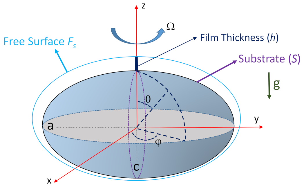
Figure 1. A schematic of the problem.
Fluids 06 00318 g001
Figure 2. Basic types of spheroids (bi-axial ellipsoids).
Fluids 06 00318 g002
Figure 3. Steady dimensionless thickness profiles at t = 1150 s, for B o = 0.0057 . The solid lines represent the results derived by employing the lubrication model, and the dashed lines represent the solutions of the Navier–Stokes equations. Film parameters: δ = 0.05 , δ = 0.01 , and δ = 0.005 . (left) Thickness profiles on an oblate spheroid for γ = 0.5 ; (right) Thickness profiles on a prolate spheroid for γ = 2 .
Fluids 06 00318 g003
Figure 4. Thickness profiles at t = 5 × 10 4 , for ( Ω d , B o ) = ( 0 , 0 ) , where γ = 0.25 , 0.5 , 1 , 2 , and 4.
Fluids 06 00318 g004
Figure 5. Variations in the steady thickness profiles for B o = 0.0057 ; the geometric parameter is γ = 0.5 , 1 , 2 . (left) Without rotation, Ω d = 0 ; (right) With rotation, Ω d = 0.1 .
Fluids 06 00318 g005
Figure 6. Variations in the steady thickness profiles for B o = 0.0057 , where the angular velocity varies on the spheroid. (left) Oblate spheroid γ = 0.5 , angular velocity Ω d = 0 , 0.05 , 0.08 ; (right) Prolate spheroid γ = 2 , angular velocity Ω d = 0 , 0.1 , 0.2 .
Fluids 06 00318 g006
Figure 7. Variations in the steady thickness profiles for the fixed angular velocity Ω d = 0.03 , where the Bond number is B o = 5 × 10 4 , 10 3 , 5 × 10 3 . (left) Oblate spheroid γ = 0.5 ; (right) Prolate spheroid γ = 2 .
Fluids 06 00318 g007
Figure 8. Evolution of the film thickness at t = 4.3 , 8.6 , 21.52 . Dashed line: initial film thickness h ( θ , t = 0 ) = 1 . (left) Oblate spheroid γ = 0.5 , dimensionless angular velocity Ω d = 0.08 ; (right) Prolate spheroid γ = 2 , dimensionless angular velocity Ω d = 0.2 .
Fluids 06 00318 g008
Figure 9. Evolution of the maximum and minimum thickness of the stationary film, as a function of the geometric parameter γ , for B o = 0.05 , 0.01 , 0.005 . (left) Non-rotating case ( Ω d = 0 ); (right) With rotation at Ω d = 0.2 .
Fluids 06 00318 g009
Figure 10. Evolution of the maximum and minimum thickness of the stationary film, as a function of the angular velocity Ω d , for B o = 0.05 , 0.01 , 0.005 . (left) Oblate spheroid, γ = 0.5 ; (right) Prolate spheroid, γ = 2 .
Fluids 06 00318 g010
Figure 11. Free surface profiles on an oblate spheroid ( γ = 0.5 ) and a prolate spheroid ( γ = 5 ) for B o = 0.0057 . The film thickness is magnified 50 times. Dashed line: interface without rotation ( Ω d = 0 ). Solid line: interface with rotation at angular velocity Ω d = 0.12 for the oblate spheroid and Ω d = 0.45 for the prolate spheroid.
Fluids 06 00318 g011
Publisher’s Note: MDPI stays neutral with regard to jurisdictional claims in published maps and institutional affiliations.