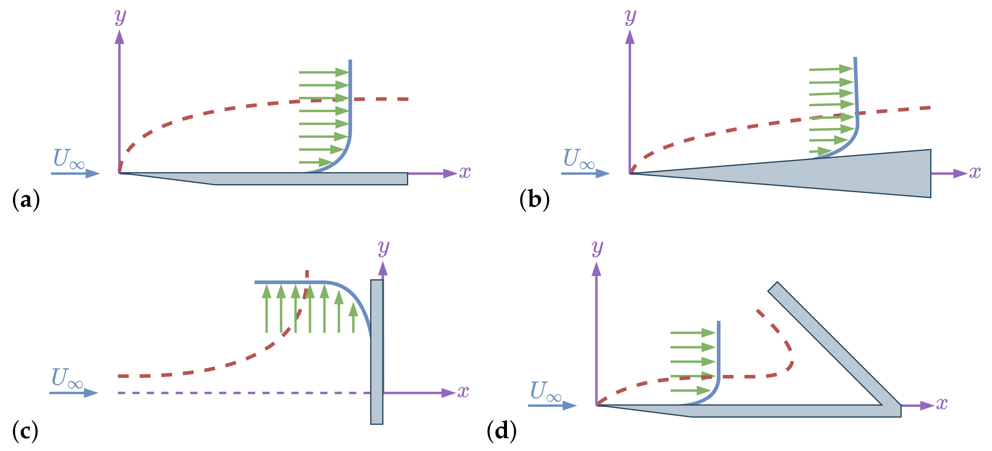
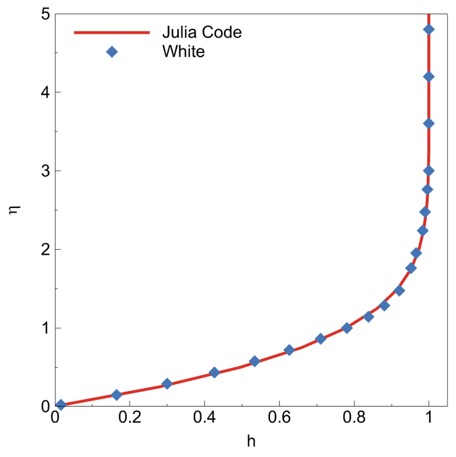
Boundary-layer velocity distribution over a wall that is perpendicular to the flow velocity vector can be represented with a similarity solution. In this subsection, Hiemenz and Homann similarity solutions will be derived from scratch and they will be solved numerically in the Julia environment. The Julia codes will be available to shorten the learning curve.
2.2.1. Hiemenz Flow Problem
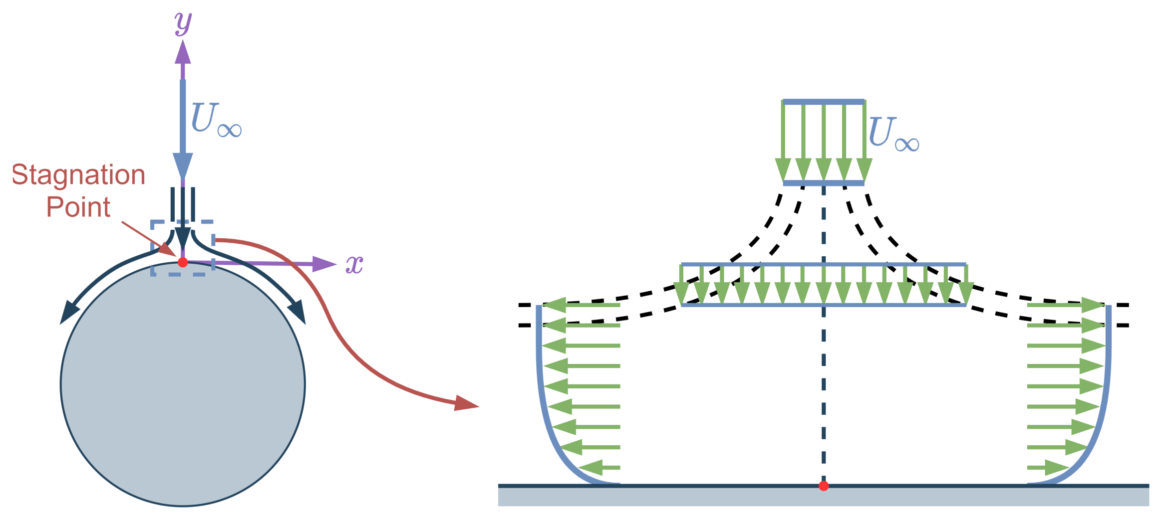
This problem is that of a fluid flow that is parallel to the
y-axis in the far-field impinging on a wall that coincides with the
x-axis. The flow which is perpendicular to a cylinder can be assumed as the Hiemenz flow around the stagnation point. The schematic description of the Hiemenz flow can be seen in
Figure 6. In the Hiemenz flow, viscous forces away from the wall become so small in comparison with the inertia forces, particularly when the Reynolds number is large. In this case, inviscid irrotational flow assumption (
) can be done. The velocity can be represented with a scalar function,
, which is the velocity potential. The velocities in the
x-direction and
y-direction can be written as:
If the dimensional Navier–Stokes equations (Equations (
1)–(
3)) are considered for this flow as well, and the continuity equation becomes:
On the wall, in the absence of viscosity, the flow can slip in the
x-direction but in
y-direction the velocity must be zero (
) because of the no-penetration boundary condition. The inviscid flow solution for the potential function was found to be:
where
a is a constant that depends on the freestream flow and the body shape. This solution satisfies the governing equations for inviscid, irrotational flow, and the boundary conditions which can be shown as:
Since potential the function is obtained, the stream-function can be calculated from the potential function. The velocity components, in terms of stream-function,
:
If Equation (
74) is integrated for
x and
y, the stream function can be found as:
In order to find the pressure in the inviscid flow, Bernoulli equation [
42] can be used. The pressure from the Bernoulli equation is:
where
is the stagnation pressure and
is the density. So far, flow is assumed as inviscid flow; however viscous forces will modify the inviscid solution, in particular in the
y-direction. Hence, the viscous velocity components can be assumed as:
If Equations (
77) and (
78) are substituted in the Navier–Stokes equations (Equations (
1)–(
3)), the final system of equations will be:
Once Equation (
79) is substituted into Equations (
80) and (
81), two non-linear ordinary differential equations can be obtained as:
It has to be noted that these two equations are coupled, which means they have to be solved together. If the
x-momentum and
y-momentum are solved for pressure, it can be seen that the pressure will be in the form of:
where
is a function depends on only
y. On the other hand, if the inviscid pressure compared with the viscous pressure as
, the pressure gradient in
x-direction and
y-direction can be found as:
If the pressure gradients are substituted into Equations (
82) and (
83), the resultant system of ordinary differential equations can be found as:
Momentum equations are decoupled in this system of equations so once,
is calculated from Equation (
87),
in the Equation (
88) can be solved. The boundary conditions of the system are:
Additionally,
can be obtained from
y-momentum equation as
. The final Equations (
87) and (
88) can be solved with the given boundary conditions; however, it is possible to get rid of the dependence on
a. In order to do that, affine transformation [
43] can be used. If it is assumed that
and
where
A and
B are constant to be determined, the
f derivative functions can be calculated as:
If Equations (
93)–(
95) substituted into the Equations (
87) and (
88) and assume that
and
, the
A and
B coefficients can be calculated as:
The given transformation allows to reduce two ordinary differential equations into one third-order ordinary differential equation as:
where the boundary conditions are:
and the velocities:
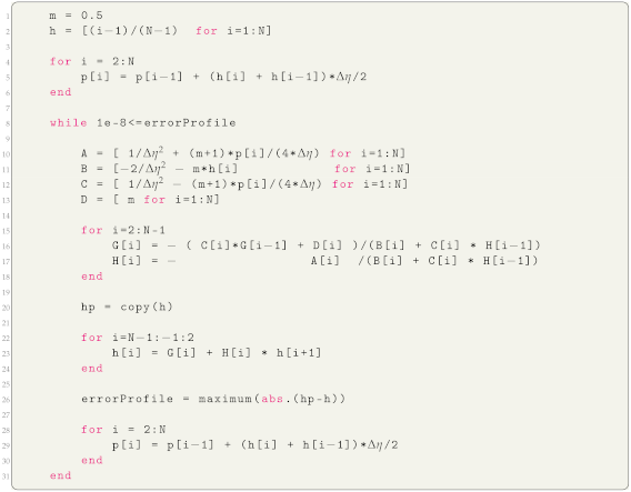
the resultant equation along with the boundary conditions can be solved with different numerical approaches such as Runge-Kutta, Runge-Kutta-Fehlberg, compact finite difference, high-order finite difference; however, in this present paper, the Thomas algorithm with finite difference discretization will be used to solve the Hiemenz profile in the Julia framework.
2.2.2. Numerical Solution of Hiemenz Flow Problem
The computational approach for the Hiemenz flow is similar to the Blasius solution since the final ordinary equation of the Hiemenz flow (Equation (
98)) is similar to the Blasius similarity solution (Equation (
20)). If it is assumed that
and
in Equation (
98), the system of equations will be:
where the boundary conditions of the system are:
If finite difference scheme is applied to the
h variable as in Blasius flow. The final system of equations will be:
where the
,
,
, and
are:
The relation between
and
is taken as it is done in Blasius flow. When Equation (
37) is substituted into the Equation (
109), the final
and
coefficients can be found as:
In order to start the calculation,
can be assumed as 0 and the
can be calculated as 0 from the boundary conditions. Once
and
are calculated,
and
can be calculated from Equations (
114) and (
115).
p can be calculated as it is done for Blasius flow:
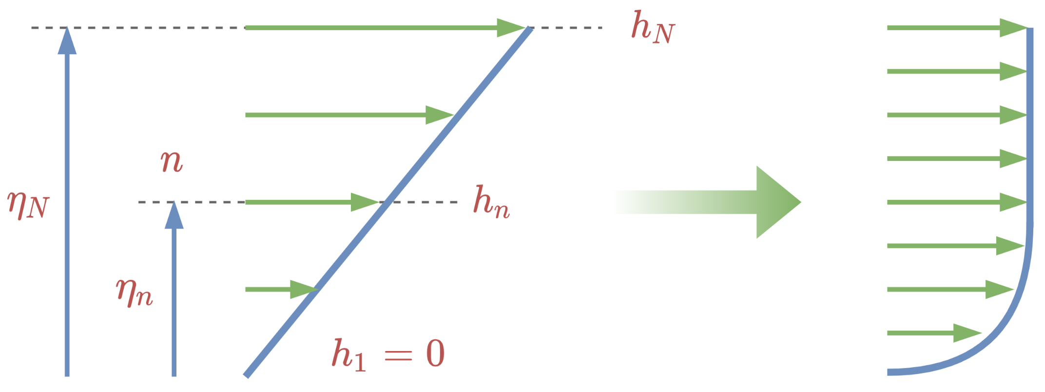
The system of equations can be implemented in the Julia environment as it is shown in Listing 4. The linear profile assumption is taken as the initial condition of
h (see
Figure 2) as it is done for the Blasius solution. The reason
and
variables are used in the Listing 4 is that the linear profile converges to the Hiemenz profile in each iteration so in order to check the difference between previous and present profiles, the solution vector from the previous iteration is copied and it is compared with the new solution vector. If the difference between these two solution vectors is less than
, which is an arbitrary limit and can be taken as
, then it can be said that the solution has converged. It has to be noted that
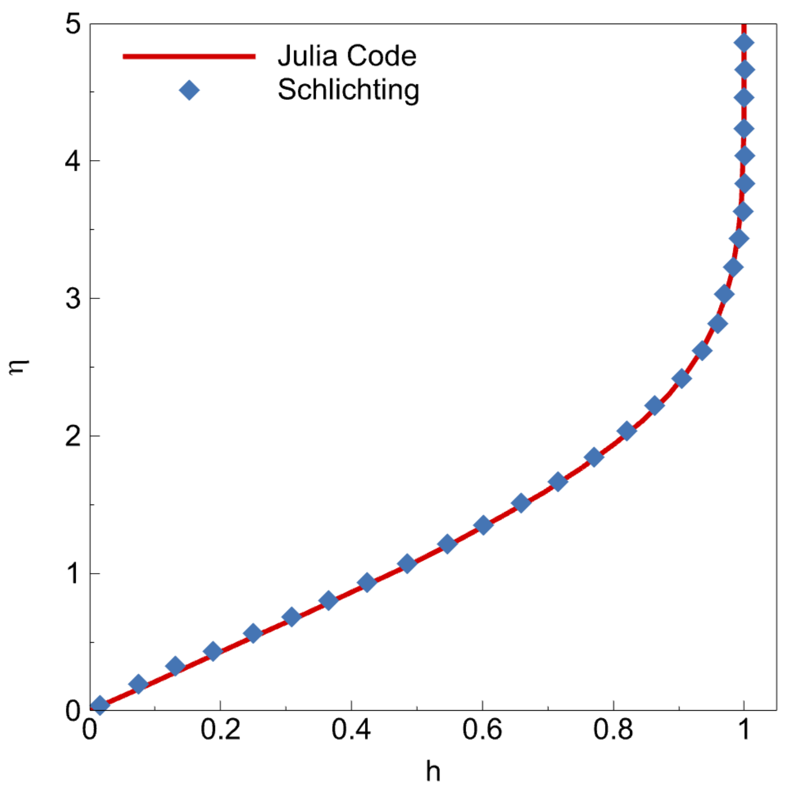
can be taken as any number; however, if it is small, the solution will be more accurate. The final result of the Hiemenz flow can be seen in
Figure 7. The results are also validated with White [
44].
2.2.3. Homann Flow Problem
Homann flow is similar to Hiemenz flow. The only difference is that Homann flow is an axisymmetric version of the Hiemenz flow. The same schematic (
Figure 6) can represent this flow as well; however, in this flow, the circle is the projection of a sphere. On the other hand, it was the projection of a cylinder in Hiemenz flow. Derivation of the Homann similarity solution has the almost same procedure as well but it uses cylindrical coordinates instead of Cartesian coordinates. The velocity components of the flow can be shown as:
As axisymmetric assumptions, derivative with respect to
(
) and
can be assumed as zero. The Navier–Stokes equations in cylindrical coordinates can be written as:
If the same procedures applied to Navier–Stokes in Cartesian coordinates for Hiemenz flow, are applied in cylindrical coordinates, the final potential function and stream function will be:
where
k is a constant which depends on the freestream flow and the body shape. The corresponding velocities are:
Once velocities are calculated, the pressure from the Bernoulli can be calculated as:
The viscous velocity components and pressure can be calculated as:
| Listing 4. Implementation of Thomas algorithm for Hiemenz profile. |
![Fluids 06 00207 i004 Fluids 06 00207 i004]() |
After the affine transformation, the final ordinary differential equation will be:
where the boundary conditions of the equation is:
If one compares Hiemenz and Homann similarity solutions (see Equations (
98) and (
132)) the only difference is the 2 in the second term. In the same manner, the computational process will be the same except for two lines of code.
2.2.4. Numerical Solution of Homann Flow Problem
Since equations of Hiemenz and Homann similarity solutions are the same except one coefficient, procedures for the solution are also the same, except for two lines of code. If it is assumed that
and
in Equation (
132), the system of equations will be:
where the boundary conditions of the system are:
If the finite difference scheme is applied to the
h variable, the final system of equations will be:
where the
,
,
, and
are:
The final
and
coefficients are the same as Hiemenz flow as well and they are:
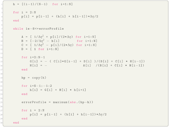
The final code can be seen in Listing 5. If the Hiemenz code (4) and Homann code (5) are compared, the only difference is in the A and C and it is because of the finite difference approach for the .
| Listing 5. Implementation of Thomas algorithm for Homann profile. |
![Fluids 06 00207 i005 Fluids 06 00207 i005]() |
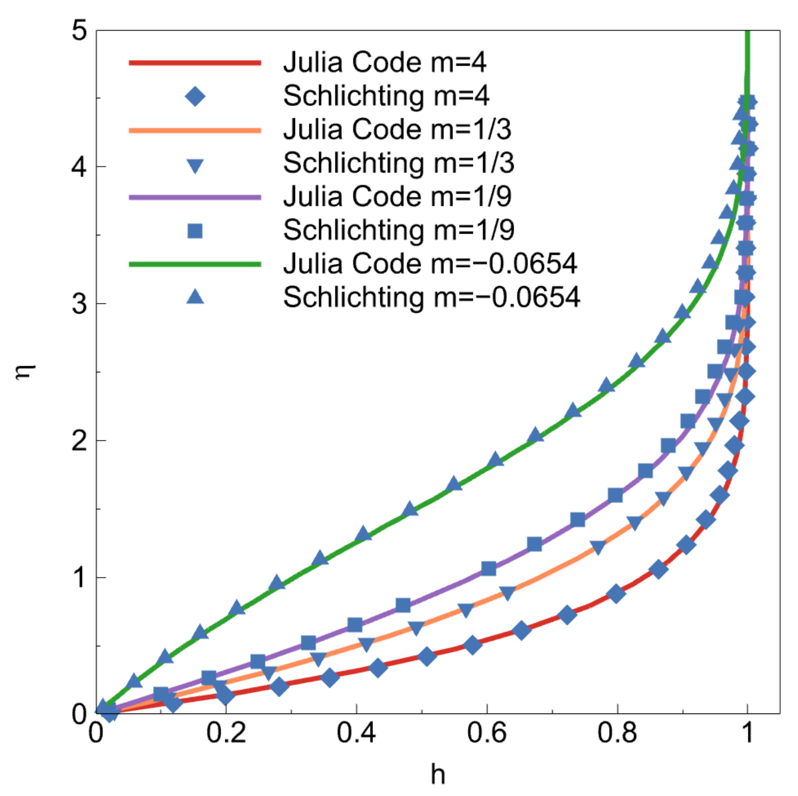
The final solution profile can be seen in
Figure 8. The results are also validated with White [
44]. One can use these results to validate their own codes. Reference data will be shared on GitHub as well.


