Abstract
In the present study, the effect of an undulated bottom topography on the radiation of water waves by a floating rectangular buoy is analyzed. Various physical quantities of interest such as the added mass and damping coefficients associated with the surge, heave, and pitch motions are analyzed for a variety of parameters associated with the incident waves and bottom undulations. The study reveals that the added mass and damping coefficients associated with the surge and pitch motions of the floating buoy vary in an oscillatory manner with the variation in wavenumber for a sinusoidally varying bottom topography. Moreover, the oscillation amplitude is higher around the primary Bragg value. Further, this oscillatory pattern and oscillation amplitude increase with an increase in the ripple amplitude and the number of ripples for a sinusoidally varying bottom. However, a reverse pattern is formed with an increase in the depth ratio. In the long-wave regime, the added mass and damping coefficient corresponding to the surge motion become higher for a protrusion-type bed profile and lower for a depression-type bed profile. However, a reverse pattern is observed in the intermediate- and short-wave regimes.
1. Introduction
The study of the radiation problem of marine floating structures provides two important hydrodynamic properties: added mass and radiation damping associated with the motion of the floating structures in water waves [1]. The added mass associated with various modes of motion of the floating body can significantly alter the natural frequency and period of the floating body’s motions. On the other hand, the radiation damping is effective in reducing the resonance in the motions of the floating body. The added mass and damping coefficients are frequency-dependent and vary with the wave properties [2]. Ref. [3] used an analytical solution technique based on the eigenfunction expansion method to study the radiation problem for a floating dock with a rectangular cross-section and uniform bottom topography. In this study, the added masses and damping coefficients are determined for the rectangular buoy in heave, sway, and roll modes of motion. Further, the associated wave excitation forces are calculated using the scattered potential and also using the radiated potentials through Haskind’s theorem. Ref. [4] used the matched asymptotic expansions method to evaluate the hydrodynamic properties of a circular cylindrical platform in the shallow water regime. The different modes of motions such as heave, surge, and pitch motions and the associated coupled motions were analyzed for various values of the draft and radius of the circular cylindrical platform. Ref. [5] used an eigenfunction expansion method to study the diffraction and radiation problem for a cylinder floating over a caisson in a finite water depth case. The hydrodynamic coefficients such as the added mass, damping coefficient, and the wave excitation forces associated with the heave, sway and roll motions of the cylinder were analyzed as a function of wave frequency and for different values of the radius of the caisson. Ref. [6] used the eigenfunction expansion method to study the effect of a bottom sill on the added mass and damping coefficients associated with the heave, sway and roll motions, wave excitation forces, and the reflection and transmission coefficients of a floating structure having a rectangular cross-section. Ref. [7] computed the added mass and damping coefficients due to the motion of a heaving cylinder in water waves. The analysis was carried out for various values of radius and draft of the circular cylinder. Ref. [8] studied the diffraction and radiation of water waves by an array of truncated cylinders, which were free to oscillate in an independent manner. It was reported that multiple scattering creates wave-free modes of motion for certain incident wave frequencies. Further, the heading angle of the incident waves played an important role in smoothing the near-trapping effects. Ref. [9] used coupled-mode theory to treat the hydrodynamic analysis of floating bodies in variable bottom topography. The bottom undulations could significantly impact the responses of the floating body in all the modes of motion. Ref. [10] calculated the wave excitation forces acting on a truncated vertical cylinder floating in deep water. For surge and pitch motions of the cylinder, an upper bound for the wave excitation forces was provided for the case of the infinite draft, and the lower bound was provided for the zero draft case. On the other hand, for the heave motion of the cylinder, the upper and lower bounds were provided for the zero draft and infinite draft cases, respectively. Ref. [11] studied the radiation of water waves in the presence of a truncated right circular cylinder located at a finite distance away from the rigid seawall. It was shown that the draft of the cylinder and the lee-sided vertical rigid wall play a vital role in determining various hydrodynamic coefficients associated with the motions of the cylinder. Ref. [12] investigated the radiation of water waves by a truncated cylinder with an arbitrary cross-section. Four different shapes of the cross-sections of the truncated cylinder, such as circular, cosine, elliptical, and quasi-elliptical, were considered in this study. It was reported that for the oscillations in heave mode, no significant differences occur in the added mass and damping coefficients for the cylinders with the same draft and cross-sections, irrespective of different shapes. Ref. [13] studied the combined scattering and radiation problem for a floating rectangular barge using a mixed Euler–Lagrangian scheme, and the associated boundary conditions were taken to be nonlinear in nature. Recently, Ref. [14] used the eigenfunction expansion method to determine the radiated potentials due to the motion of a rectangular buoy floating over a sill. The effect of sill height and width on the sway, heave, and roll modes of motion of the rectangular buoy were analyzed in a detailed manner. In all the aforementioned studies, the radiation problem was analyzed by considering either uniform water depth or step-type bottom topography.
In the real ocean, the seabed is not uniform in nature. Therefore, it is important to analyze the radiation problem when a rigid body floats over an undulated bottom topography. Ref. [15] used a coupled-mode theory to analyze the hydroelastic responses of flexible plates floating over a variable bottom. Ref. [16] presented the full solutions of wave scattering by flexible sheets having variable thickness and floating over a variable sea bed. Ref. [17] used a mild-slope approximation based mathematical model to determine solutions for membrane-coupled gravity waves when a membrane structure was floating at the ocean surface and over an undulated seabed. Ref. [18] used a coupled eigenfunction expansion-boundary element method to study the interaction of water waves with breakwaters placed over a sloping seabed. It was shown that the sloping bottom profile plays an important role in wave diffraction by the breakwater. Using the same solution methodology as used in [18,19] studied the combined scattering and radiation problem for an OWC (oscillating water column) device placed over an undulated seabed. The effect of a sinusoidally varying bottom topography on the wave radiation was discussed in detail. Recently, Ref. [20] studied the effect of bottom undulations on Bragg resonance phenomena in the presence of a floating flexible porous plate. It was found that the flexible floating plate has a significant impact on the Bragg resonance phenomena. From the aforementioned literature, it is clear that the bottom undulation plays a major role on the wave radiation by floating bodies.
In this paper, the effect of varying bottom topography on the radiation of water waves by a floating rectangular buoy is analyzed. Various hydrodynamic coefficients such as the added mass and radiation damping associated with various modes of motion of the floating body are studied for a variety of wave and bottom parameters. The overall structure of the paper is the following. In Section 2, the associated boundary value problem and related mathematical formulation are provided. Section 3 contains the detailed solution methodology. In Section 4, the associated results and discussions are provided. Finally, a summary of the present study is provided in Section 5.
2. Mathematical Formulation
In this section, the governing equation and related boundary conditions associated with the motions of a freely floating rectangular buoy over an undulated bottom bed are provided. The schematic diagram of the physical problem is given in Figure 1. For the sake of mathematical modeling, a two-dimensional rectangular Cartesian co-ordinate system is taken in which the x-axis coincides with the mean free surface, and the positive z-axis is taken vertically upward direction (see Figure 1). The floating buoy with a draft d and width w occupies the position along the x-axis, and the buoy floats over an undulated bed extended between and . Beyond the undulated bed region, the water depth is uniform in nature. To close the domain, two auxiliary boundaries at and are taken sufficiently far from the undulated bed region so that the effect of local wave modes diminishes at those boundaries. The water and the associated motion are assumed to be inviscid, incompressible, and irrotational in nature. Further, the water waves are assumed to be time-harmonic in nature.
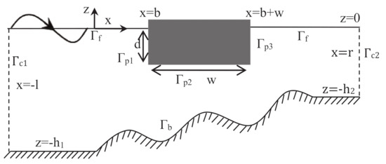
Figure 1.
Vertical cross section of a rectangular buoy floating over an undulated bottom.
These assumptions guarantee the existence of the velocity potential of the form . Here, represents the angular frequency of the incident wave and related with the progressive wavenumber by the dispersion relation . Since only the radiation problem is considered in the present study, the velocity potential can further be decomposed into the following form
where represent the surge, heave and pitch motions respectively. Further, the radiated velocity potential can be written as , where represents the amplitude of the motion of the floating buoy (see [3] for details). Now, the radiated velocity potentials satisfy the Laplace equation as the following
At the interface between the air and water, i.e., at , the following linearized boundary condition holds
where is the wavenumber associated with the deep water waves. In Equation (3) and subsequent formulation, represents the normal derivative. Since the water bed is impermeable in nature, the no-flow boundary condition gives
Here, the profile of the bottom boundary is represented by and is given by
The boundary conditions on the buoy surface are given by (see [3] for details)
where is the center of rotation. Finally, the boundary conditions on for are given by
where is the positive real root of the dispersion relation .
3. Numerical Solutions Based on BEM
In this section, the BVP (boundary value problem) formulated in Section 2 is solved numerically using the boundary element method (BEM). In the BEM-based solution technique, the BVP is transformed into a system of integral equations. For the same, Green’s second identity is used with the appropriate free-space Green’s function. In the present problem, the free-space Green’s function is given by
Various properties of the aforementioned Green’s function are available in [21]. Using the boundary conditions Equations (3)–(9), we get the following integral equations
4. Results & Discussion
In this section, various results associated with the radiation problem, as described in Section 2, are plotted and discussed. To plot the figures, the MATLAB software was used. Two important physical quantities associated with the radiation problem are the added mass and radiation damping. The expressions for the added mass and radiation damping are given by
where , and . Here, is the normal vector directed out of the buoy’s surface. Therefore, the non-dimensional form of the added mass and radiation damping are given by
where and are the added mass and damping coefficient corresponding to surge (), heave () and pitch () motions of the buoy. In the present study, three different bed profiles are considered and the same are given by
where , a and are the ripple amplitude and the number of ripples. Moreover, with represents the bed wavelength. It is to be noted that the sinusoidal and doubly periodic bed profiles as provided in Equations (21) and () are taken from [20]. These types of sinusoidally varying bed profile are generally found in the nearshore regions [22]. On the other hand, the shapes of the type-III bed profile, as given in Equation (), depend on the parameter . For example, represents the protrusion, sloping-, concave- and depression-type bed profiles, respectively (see [20] for details). Type-III bed profiles are generally formed due to the sediment transport and erosion beneath the sea. The values of the wave and structural parameters are taken as follows: m, , , , , , , unless otherwise mentioned. Further, the type-I bed profile is considered for most of the analysis unless otherwise mentioned.
4.1. Numerical Convergence in BEM
In this subsection, the numerical convergence of the solutions based on the BEM is discussed for specific cases.
In BEM, the numerical convergence of the solutions depend on the panel size , which is related to the incident wavelength by the relation (see [23] for details)
where is the constant of proportionality. It is observed from Table 1 that the values of and (for ) converge up to three decimal places for . In the rest of the numerical computations, the panel size used in BEM discretization is taken corresponding to .

Table 1.
Comparative study of and (for ) for various values of with .
4.2. Comparison with Existing Results
To validate the present BEM-based numerical results, certain results obtained by the present BEM method are compared with the standard results available in the literature. In Figure 2, the added mass corresponding to the surge motion of the buoy is plotted as a function of non-dimensional wavenumber . It is to be noted that the lines represent the present BEM-based solutions and the symbols represent the solutions available in [3]. It is seen that the present results match well with the results of [3]. This shows the accuracy of the present numerical computations.
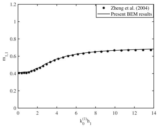
Figure 2.
Variation of vs .
4.3. Effect of Bottom Undulations on the Added Mass and Radiation Damping
In this section, the effect of bottom undulations on the added mass and damping coefficients corresponding to surge, heave, and pitch motions are analyzed in a detailed manner. The results are plotted as a function of the non-dimensional frequency parameter .
In Figure 3, the variation of (a) the added mass and (b) the damping coefficient corresponding to surge motion are plotted as a function of the non-dimensional frequency parameter for various values of ripple amplitude of the sinusoidally varying bottom. It is seen that the added mass and damping coefficient vary in an oscillatory manner with the variation in . Moreover, the oscillation amplitude is higher for . This may happen due to the effect of Bragg resonance around the primary Bragg value . In addition, the amplitude of the oscillation in the added mass and damping coefficients are larger for higher values of ripple amplitude . Further, Figure 3a shows that the overall trend of the added mass is decreasing in nature as the wavenumber takes higher values. On the other hand, Figure 3b reveals that the damping coefficient initially increases with an increase in wavenumber . However, a reverse trend is observed for higher values of the wavenumber , i.e., in the short wave regime.
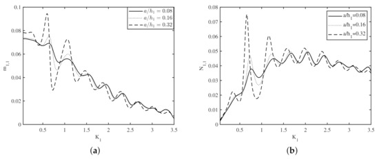
Figure 3.
Variation of (a) and (b) vs for different .
Figure 4 demonstrates the variation of (a) the added mass and (b) the damping coefficient as a function of non-dimensional frequency parameter for various values of number of ripples of the sinusoidally varying bottom. The overall pattern of the added mass and damping coefficient as a function of wavenumber are similar in nature as that of Figure 3. Further, it is seen that the oscillatory pattern in the added mass and damping coefficient increases with an increase in the number of ripples of the seabed.
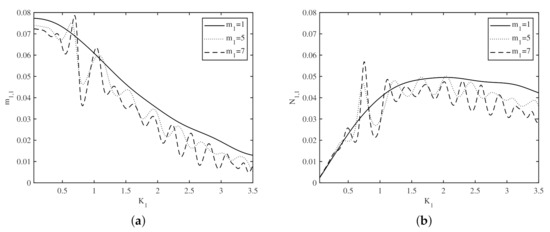
Figure 4.
Variation of (a) and (b) vs for different .
Figure 5 delineates (a) the added mass and (b) the damping coefficient versus the wavenumber as a function of depth ratio . The overall patterns of and as a function of are similar in nature as those of Figure 3 and Figure 4. Moreover, it is observed that the oscillatory pattern in the added mass and damping coefficient increases for lower values of the depth ratio . This is obvious as for lower values of the depth ratio , the gap between the free surface and the bottom reduces and as a result, the effect of bottom on waves radiation becomes stronger.
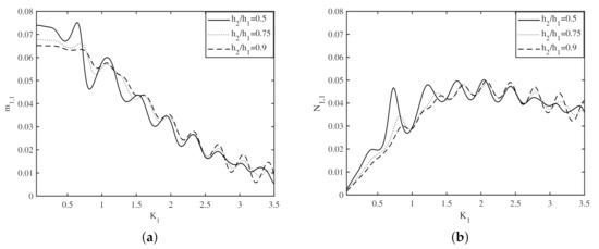
Figure 5.
Variation of (a) and (b) vs for different .
Figure 6 shows the variation of (a) the added mass and (b) the damping coefficient corresponding to heave motion as a function of wavenumber for various values of ripple amplitude of the sinusoidally varying bottom. Figure 6a demonstrates that the added mass is oscillatory in nature with the variation in and this oscillatory pattern diminishes for higher values of , i.e., in the short-wave regime. Further, the oscillation amplitude increases as the ripple amplitude of the bottom increases. A similar pattern was seen in Figure 3a. On the other hand, Figure 6b illustrates that the damping coefficient decreases rapidly with an increase in wavenumber . In addition, it is seen that negligible variation in the damping coefficient occurs due to the variation in ripple amplitude , except for certain values of the wavenumber .
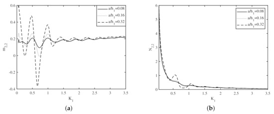
Figure 6.
Variation of (a) and (b) vs for different .
Figure 7 demonstrates the variation of (a) the added mass and (b) the damping coefficient as a function of the non-dimensional frequency parameter for various values of the number of ripples of the sinusoidally varying bottom. The overall pattern of the added mass and damping coefficient as a function of the wavenumber are similar in nature as that of Figure 6. Moreover, it is observed from Figure 7a that the oscillation amplitude of the added mass increases with an increase in the number of ripples of the sinusoidally varying bottom. On the other hand, Figure 7b illustrates that there are no significant variations observed in the damping coefficient as the wavenumber varies.
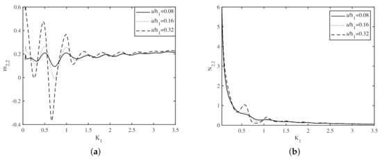
Figure 7.
Variation of (a) and (b) vs for different .
Figure 8 delineates (a) the added mass and (b) the damping coefficient versus the wavenumber as a function of depth ratio . The overall pattern of and as a function of are similar in nature as that of Figure 6 and Figure 7. Moreover, it is observed that the oscillatory pattern in the added mass and damping coefficient diminishes for higher values of the depth ratio . This is obvious as for higher values of the depth ratio , the gap between the free surface and the bottom increases, and as a result, the effect of the seabed on wave radiation becomes less significant.
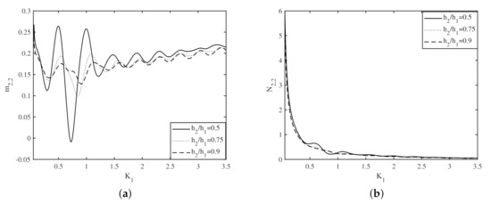
Figure 8.
Variation of (a) and (b) vs for different .
Figure 9 shows the variation of (a) the added mass and (b) the damping coefficient corresponding to pitch motion as a function of wavenumber for various values of ripple amplitude of the sinusoidally varying bottom. The overall patterns of and as a function of are similar in nature as that of Figure 3. In addition, the oscillation amplitudes in the added mass and damping coefficient increase for higher values of ripple amplitude . Similar observations were reported in Figure 3a,b.
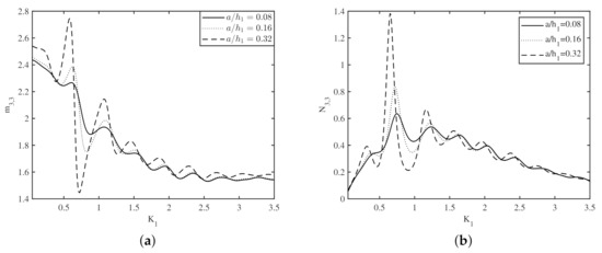
Figure 9.
Variation of (a) and (b) vs for different .
Figure 10 demonstrates the variation of (a) the added mass and (b) the damping coefficient as a function of the non-dimensional frequency parameter for various values of number of ripples of the sinusoidally varying bottom. The overall patterns of the added mass and damping coefficient as a function of wavenumber are similar in nature as that of Figure 4. Moreover, the oscillation amplitudes in the added mass and damping coefficient increase with an increase in the number of ripples of the seabed. A similar observation was reported in Figure 4.
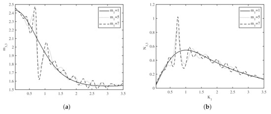
Figure 10.
Variation of (a) and (b) vs for different .
Figure 11 delineates (a) the added mass and (b) the damping coefficient versus the wavenumber as a function of depth ratio . The overall patterns of and as a function of are similar in nature as that of Figure 5. Moreover, it is observed that the oscillatory pattern in the added mass and damping coefficient increases for lower values of the depth ratio . A similar pattern was reported in Figure 5a,b.
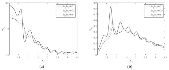
Figure 11.
Variation of (a) and (b) vs for different .
Figure 12 demonstrates the variation of (a) the added mass and (b) the damping coefficient as a function of wavenumber for (a) type-I and (b) type-II bed profiles. It is observed that the added mass and damping coefficient corresponding to surge motion are oscillatory in nature for both type-I and type-II bed profiles. However, the oscillation amplitude is greater for the type-II bed profile compared to the type-I bed profile. The reason for this is that for the type-II bed profile, the resultant ripple amplitude is higher than the type-I bed profile. Similar observations were reported in Figure 3.
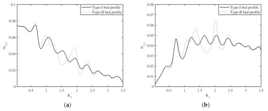
Figure 12.
Variation of (a) and (b) vs for (a) type-I and (b) type-II bed profiles.
Figure 13 shows the variation of (a) the added mass and (b) the damping coefficient as a function of the wavenumber for different values of the shape parameter in type-III bed profile. It is observed that the added mass and damping coefficient corresponding to surge motion are oscillatory in nature in short-wave regime. Moreover, this oscillatory pattern diminishes in the long- and intermediate-wave regimes. This pattern is quite different from the type-I and type-II bed profiles. Further, it is seen that the added mass and damping coefficient increase with an increase in in the long-wave regime. However, a reverse pattern is observed in the intermediate- and short-wave regimes.
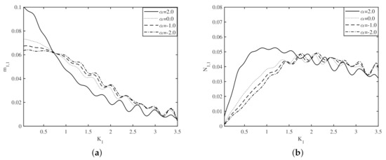
Figure 13.
Variation of (a) and (b) vs for different in type-III bed profile.
It is to be noted that to compare the hydrodynamic coefficients associated with the radiation problem in different bed profiles, the results and discussions for the added mass and damping coefficient associated with the surge motion are provided. A similar analysis can easily be done for the added mass and damping coefficient associated with the heave and pitch motions.
5. Conclusions
In the present study, the radiation of water waves by a rectangular buoy floating over an undulated seabed is analyzed. Two important hydrodynamic parameters—added mass and radiation damping—associated with various modes of motion of the floating body, are studied for a variety of wave and structural parameters. It is observed that the added mass and damping coefficients associated with the surge and pitch motions of the floating buoy vary in an oscillatory manner with the variation in wavenumber . Moreover, the oscillation amplitude is higher for . This occurs due to the effect of Bragg resonance around the primary Bragg value, i.e., around . In addition, the oscillation amplitude in the added mass and damping coefficients are larger for higher values of ripple amplitude of the sinusoidally varying bottom. Further, it is seen that the oscillatory pattern in the added mass and damping coefficient corresponding to surge and pitch motions increases with an increase in the number of ripples of the seabed. However, a reverse trend is observed with an increase in the depth ratio. On the other hand, the added mass corresponding to the heave motion is oscillatory in nature with the variation in wavenumber , and this oscillatory pattern diminishes in the short-wave regime. Further, the amplitude of the aforementioned oscillatory pattern increases as the ripple amplitude of the bottom and the number of ripples increase. Moreover, the damping coefficient associated with the heave motion decreases rapidly with an increase in wavenumber . In addition, a negligible variation in the damping coefficient occurs due to the variation in ripple amplitude, number of ripples and depth ratio. A comparison between the results obtained for type-I and type-II bed profiles reveals that the oscillation amplitude in the added mass and damping coefficients are higher for the type-II bed profile as compared with type-I bed profile. Further, in the long-wave regime, the added mass and damping coefficient corresponding to surge motion increased for the protrusion-type bed profile and lower for the depression-type bed profile. However, a reverse pattern is observed in the intermediate- and short-wave regimes. The present boundary element method-based solution technique is robust and efficient, and can be easily applicable to more complex problems that arise in the field of ocean and coastal engineering.
Author Contributions
Conceptualization, S.K.; Formal analysis, K.T.; Funding acquisition, S.K.; Investigation, S.K.; Methodology, K.T. and S.K.; Software, K.T.; Supervision, S.K.; Validation, K.T.; Writing—original draft, K.T. and S.K. All authors have read and agreed to the published version of the manuscript.
Funding
K.T. and S.K. acknowledge the financial support received through the DST Project: DST/INSPIRE/04/2017/002460 to pursue this research work. Further, supports were received through the RIG project: BITS/GAU/RIG/2019/H0631 and Additional Competitive Research Grant: BITS/GAU/ACRG/2019/H0631 provided by BITS-Pilani, Hyderabad Campus.
Conflicts of Interest
The authors declare no conflict of interest.
References
- Lee, J.F. On the heave radiation of a rectangular structure. Ocean Eng. 1995, 22, 19–34. [Google Scholar] [CrossRef]
- Newman, J.N. Marine hydrodynamics; The MIT Press: Cambridge, MA, USA, 2018. [Google Scholar]
- Zheng, Y.H.; You, Y.G.; Shen, Y.M. On the radiation and diffraction of water waves by a rectangular buoy. Ocean Eng. 2004, 31, 1063–1082. [Google Scholar] [CrossRef]
- Drobyshevski, Y. Hydrodynamic coefficients of a floating, truncated vertical cylinder in shallow water. Ocean Eng. 2004, 31, 269–304. [Google Scholar] [CrossRef]
- Wu, B.J.; Zheng, Y.H.; You, Y.G.; Sun, X.Y.; Chen, Y. On diffraction and radiation problem for a cylinder over a caisson in water of finite depth. Int. J. Eng. Sci. 2004, 42, 1193–1213. [Google Scholar] [CrossRef]
- Shen, Y.M.; Zheng, Y.H.; You, Y.G. On the radiation and diffraction of linear water waves by a rectangular structure over a sill. Part I. Infinite domain of finite water depth. Ocean Eng. 2005, 32, 1073–1097. [Google Scholar] [CrossRef]
- Bhatta, D.D. Computation of added mass and damping coefficients due to a heaving cylinder. J. Appl. Math. Comput. 2007, 23, 127–140. [Google Scholar] [CrossRef]
- Siddorn, P.; Taylor, R.E. Diffraction and independent radiation by an array of floating cylinders. Ocean Eng. 2008, 35, 1289–1303. [Google Scholar] [CrossRef]
- Belibassakis, K.A. A boundary element method for the hydrodynamic analysis of floating bodies in variable bathymetry regions. Eng. Anal. Bound. Elem. 2008, 32, 796–810. [Google Scholar] [CrossRef]
- Finnegan, W.; Meere, M.; Goggins, J. The wave excitation forces on a truncated vertical cylinder in water of infinite depth. J. Fluids Struct. 2013, 40, 201–213. [Google Scholar] [CrossRef]
- Zheng, S.; Zhang, Y. Wave radiation from a truncated cylinder in front of a vertical wall. Ocean Eng. 2016, 111, 602–614. [Google Scholar] [CrossRef]
- Yu, H.; Zheng, S.; Zhang, Y.; Iglesias, G. Wave radiation from a truncated cylinder of arbitrary cross section. Ocean Eng. 2019, 173, 519–530. [Google Scholar] [CrossRef]
- Li, Y.; Xu, B.; Zhang, D.; Shen, X.; Zhang, W. Numerical Analysis of Combined Wave Radiation and Diffraction on a Floating Barge. Water 2020, 12, 205. [Google Scholar] [CrossRef]
- Liu, X.; Wang, X.; Xu, S.; Ding, A. Influences of a varying sill at the seabed on two-dimensional radiation of linear water waves by a rectangular buoy. J. Offshore Mech. Arct. Eng. 2020, 142, 041202. [Google Scholar] [CrossRef]
- Belibassakis, K.A.; Athanassoulis, G.A. A coupled-mode model for the hydroelastic analysis of large floating bodies over variable bathymetry regions. J. Fluid Mech. 2005, 531, 221–249. [Google Scholar] [CrossRef]
- Bennetts, L.G.; Biggs, N.R.T.; Porter, D.A. Multi-mode approximation to wave scattering by ice sheets of varying thickness. J. Fluid Mech. 2007, 579, 413–443. [Google Scholar] [CrossRef]
- Manam, S.R.; Kaligatla, R.B. A mild-slope model for membrane-coupled gravity waves. J. Fluids Struct. 2012, 30, 173–187. [Google Scholar] [CrossRef]
- Koley, S.; Sarkar, A.; Sahoo, T. Interaction of gravity waves with bottom-standing submerged structures having perforated outer-layer placed on a sloping bed. Appl. Ocean Res. 2015, 52, 245–260. [Google Scholar] [CrossRef]
- Koley, S.; Trivedi, K. Mathematical modeling of oscillating water column wave energy converter devices over the undulated sea bed. Eng. Anal. Bound. Elem. 2020, 117, 26–40. [Google Scholar] [CrossRef]
- Koley, S. Water wave scattering by floating flexible porous plate over variable bathymetry regions. Ocean Eng. 2020, 214, 107686. [Google Scholar] [CrossRef]
- Katsikadelis, J.T. The Boundary Element Method for Engineers and Scientists: Theory and Applications; Academic Press: Cambridge, MA, USA, 2016. [Google Scholar]
- Mei, C.C.; Stiassnie, M.A.; Yue, D.K. Theory and Applications of Ocean Surface Waves; World Scientific Publishing Company: Singapore, 2018; Volume 42. [Google Scholar]
- Koley, S. Integral Equation and Allied Methods for Wave Interaction with Porous and Flexible Structures. Ph.D. Thesis, IIT Kharagpur, Kharagpur, India, 2016. [Google Scholar]


Publisher’s Note: MDPI stays neutral with regard to jurisdictional claims in published maps and institutional affiliations. |
© 2021 by the authors. Licensee MDPI, Basel, Switzerland. This article is an open access article distributed under the terms and conditions of the Creative Commons Attribution (CC BY) license (http://creativecommons.org/licenses/by/4.0/).