Article

Assessing the Applicability of the Structure-Based Turbulence Resolution Approach to Nuclear Safety-Related Issues

Department of Nuclear Science and Engineering, Massachusetts Institute of Technology, Cambridge, MA 02139, USA
*
Author to whom correspondence should be addressed.
Fluids 2021, 6(2), 61; https://doi.org/10.3390/fluids6020061
Submission received: 6 November 2020 / Revised: 26 January 2021 / Accepted: 27 January 2021 / Published: 1 February 2021

Abstract

:
The accuracy of computational fluid dynamics (CFD) predictions plays a fundamental role in supporting the operation of the current nuclear reactor fleet, and even more importantly the licensing of advanced high-efficiency reactor concepts, where local temperature oscillations driven by thermal striping, cycling and stratification can limit the structural performance of vessels and components. The complexity of the geometrical configurations, coupled to the long operational transients, inhibits the adoption of large eddy simulation (LES) methods, mandating the acceptance of the more efficient Reynolds-averaged Navier-Stokes (RANS)-based models, even though they are unable to provide a complete physical description of the flow in regions dominated by complex unsteady coherent structures. A new strategy has been proposed and demonstrated at Massachusetts Institute of Technology (MIT) toward the enhancement of unsteady Reynolds-averaged Navier-Stokes (URANS) predictions, using local resolution of coherent turbulence, to provide higher fidelity modeling in support of safety-related issues. In this paper, a comprehensive assessment of the recently proposed Structure-based (STRUCT- ε ) turbulence model is presented, starting from fundamental validation of the model capabilities and later focusing on a representative safety-relevant application, i.e., thermal mixing in a T-junction. Solutions of STRUCT- ε , the widely used Realizable k ε model (RKE) and Large Eddy Simulation with Wall-Adapting Local Eddy-viscosity subgrid scale closure (LES-WALE) are compared against the experimental data. Both the velocity and temperature fields predicted by the STRUCT- ε model are in close agreement with the high-fidelity data from the experiments and reference LES solutions, across all validation cases. The approach demonstrates the potential to address the accuracy requirements for application to nuclear safety-related issues, by resolving the turbulent flow structures, while the computational efficiency provides the ability to perform consistent uncertainty quantification.

Graphical Abstract

1. Introduction

Computational fluid dynamics (CFD) has been widely adopted to aid the design of advanced engineering systems where the simulation of turbulent flow phenomena has been made possible by the availability of large computational facilities and the advancement of numerical models to address complex flow problems. The nuclear industry has been seeking to extend the use of CFD in support of safety-related issues [1] which are characterized by unsteady turbulent flow with the potential to limit the structural performance of vessels and components. Scale-resolving large eddy simulation (LES) models have demonstrated the ability to provide the necessary resolution of flow and temperature oscillations, while not providing the computational efficiency required to address the uncertainty quantification requirements on large and complex geometrical configurations; on the other hand, Reynolds-averaged Navier-Stokes (RANS)-based solutions are not able to reproduce the turbulent unsteady features that lead to accelerated thermal and mechanical driven failures [2]. In order to extend the applicability of CFD to safety analysis, hybrid turbulence models are sought to deliver accurate solutions while enjoying substantial cost reduction over the LES methods.
While a systematic evaluation of all hybrid model proposals is out of the scope of this paper, a valuable review was provided by [3]. In this paper, the mainstream hybrid turbulent models are classified into large families to compare their inherent assumptions. The very-large eddy simulation (VLES) proposed by Speziale [4] and the detached-eddy simulation (DES) proposed by Spalart [5] are two hybrid turbulent models which have significant impacts on all the hybrid turbulent models. VLES was originally proposed as a somewhat universal model which can operate as DNS, LES or URANS on different computational grid sizes, while in comparison, DES transitions zonally between the URANS and LES models. Limitations of both these approaches have been made apparent by industrial practice. Following the introduction of VLES and DES, a large number of hybrid variants have been proposed. Among those, two of particular interest are the partially averaged Navier-Stokes (PANS) by Girimaji [6] and the scale-adaptive simulation (SAS) by Menter [7,8]. SAS is a complete hybrid turbulence closure that controls the level of turbulence resolution based on local length scales comparison. While successful on a number of external flow applications, the SAS model has shown important failures in internal flow applications, in particular when applied to a common safety-related issue, represented by turbulent mixing in a T-junction [2]; results of temperature and velocity fields demonstrated significant discrepancies, with errors much larger even than any of the RANS solutions. In the PANS approach, the goal is to bridge the gap between DNS, LES and URANS by prescribing, a-priori, a desired level of resolution. The PANS model introduces a damping ratio for the turbulent kinetic energy and turbulent dissipation rates, aiming to model the partially averaged statistics of the flow, resembling very closely the original idea of VLES. The model terms are controlled through local damping ratios to resolve only part of the turbulent kinetic energy, while not necessarily being directly applicable in regions with homogenous turbulence.
While some of the hybrid turbulent models are able to deliver improved accuracy on specific test cases compared to the classic URANS models, they are usually coupled with purposely crafted mesh configurations. When they are applied on challenging industrial applications or complex blind tests, unexpected large errors are usually observed and the solutions are sometimes higher than the classic URANS models [2]. Most importantly, hybrid turbulent models usually do not fulfill the grid convergence requirement on complex flow scenarios that are typically caused by the adoption of grid dependent hybridization parameters. Due to those limitations, advanced hybrid models are highly sought to capture complex flow scenarios.
Aiming at addressing the discussed consistency and applicability issues, a STRUCTure-based (STRUCT) hybrid turbulence approach was proposed by Lenci and Baglietto [9]. This new approach leverages the robustness and computational efficiency of the classic URANS model in fully developed regions while eliminating its limitations in regions where the assumptions of URANS are not met. Adopting a similar strategy to SAS and PANS, the STRUCT model modifies the URANS equations without solving the filtered LES. Rather than relying on length scales (e.g., SAS has been shown to fail for internal flow application [2]) or non-generally applicable scaling coefficients (e.g., PANS), STRUCT identifies the turbulent structures by identifying regions of timescale overlap and locally modifying the turbulent viscosity. The STRUCT model does not rely on mesh dependent parameters and has demonstrated robust applicability on a range of complex flow scenarios [9,10,11,12].
Stemming from the idea of resolving the turbulent structures by dynamically reducing the turbulent eddy viscosity, an advancement of the STRUCT model, i.e., STRUCT- ε , is proposed by Xu [13] and eliminates sensitivity of the activation strategy to the boundary conditions, by introducing an implicit activation term in the ε equations of the non-linear k ε formulation. In this paper, the performance of the newly proposed model is assessed on selected validation cases and on the safety-related thermal mixing in a T-junction. The realizable k ε model and a reference LES solutions are adopted for comparison in addition to the experimental data.

2. Turbulence Models Description

The turbulence models adopted in the present study include the Realizable k ε model (RKE), the STRUCT-   ε model and the LES-WALE model. The theory of the models is discussed briefly in this section.

2.1. Realizable k- ε Model

The k ε model [14] still remains one of the most widely adopted turbulence models, thanks to the extremely broad accumulated industrial experience. It has demonstrated considerable robustness, and most valuably, its shortcomings are well understood and its failure predictable. The k ε model assumes a linear eddy viscosity model which overpredicts the eddy viscosity in complex strain conditions involving curvature, vortices, rotations, etc. A large number of k ε model variants exist aimed at improving some specific aspect of the predictions, among which the Realizable k ε (RKE) model has shown comparable robustness with consistently improved accuracy, gaining widespread popularity as a reference CFD solution [15].
The RKE model was proposed by Shih aiming to incorporate sensitivity to complex strains, leveraging the long experience with explicit algebraic Reynolds stress formulations [16]. The model name is derived from the nonconstant expression of C μ which ensures that all normal stresses are positive. The main feature of the model is however the additional term in the turbulent dissipation rate ε equation, which reduces the viscosity overprediction in complex strains. While the RKE model cannot, in large part, overcome the limitations of a linear eddy viscosity formulation, it generally provides improved predictions for the complex flow scenarios. Due to the improved performance and its robust behavior, RKE with two-layer wall treatment is therefore chosen as the reference model to be compared in this research.

2.2. STRUCT- ε Model

The original STRUCT hybrid model proposed by Lenci [9] relies on a baseline cubic k ε model [17,18] while activating the hybridization parameters via a local time-scale-based criterion. The hybridization parameters compare the second invariant of the velocity gradient tensor, I I ¯ , representing the resolved time scales of the turbulent structures, with the averaged modeled time scales, k / ε . In regions where the timescales overlap, the turbulent eddy viscosity is reduced locally by the hybridization parameter to increase turbulence resolution, thus resolving more turbulent structures. Extensive studies found that the STRUCT model shows consistent grid convergence and approaches the reference LES solutions on URANS type mesh configurations [9,19]. Demonstrations of the STRUCT model capabilities have been presented for thermal mixing in T-junctions [10,11], triple-jet mixing [12] and cross flow in a helical-coiled tube bundle [20].
The original STRUCT formulation adopts a differential Lagrangian operator to transport the local modeled time scale to fully obtain closures. This approach demonstrated undesirable sensitivity to the boundary conditions for external flow cases. Since the modeled scale on the inlet boundary (as well as all surrounding boundaries) is defined based on the ratio between the turbulent kinetic energy, k , and turbulent dissipation rate, ε , this can lead to unexpected hybrid activation based on the users’ definition. In addition, the solution of an additional transport equation increases the computational cost by approximately 10% [9] when compared to the baseline URANS model.
To overcome the limitations of the transported average STRUCT formulation, which is referred to as STRUCT-T for future reference, the STRUCT- ε model was recently proposed by Xu and Baglietto [13]. Rather than calculating the reduction parameter based on explicit comparison between the resolved and modeled time scales, the new model introduces an additional source term in the ε equation to implicitly reduce the eddy viscosity, which directly compares the modeled and resolved time scales. The STRUCT- ε model formulation is as follows:
k t + u ¯ j k x j = x j ν + ν t σ k k x j + P k ε   ^ m a t h e m a t i c a l   f o r m   o f   t h e   P I D b a s e d   b u b b l e   c o n t r o l l e r   i s   g i v e n   b e l o w s   t h e   b u b b l e   l o c a t i o n   a n d   v e l o c i t y   a n d   u s e s   t h o s e   v a r i a b
ε t + u ¯ j ε x j = x j ν + ν t σ k ε x j + C ε 1 ε k P k C ε 2 ε 2 k + C ε 3 k I I ¯
P k = τ i j u ¯ i x j
ν t = C μ k 2 ε
σ k = 1.0 ,   σ ε = 1.3 ,   C ε 1 = 1.44 ,   C ε 2 = 1.92 ,   C ε 3 = 1.5
where u ¯ j is the mean velocity. ν and ν t are the dynamics and turbulent eddy viscosities, respectively. P k is the production term of turbulent kinetic energy. I I ¯ is the second invariant of velocity gradient and defined as 1 2 ( Ω 2 S 2 ). The constants of σ k , σ ε , C ε 1 and C ε 2 come from Launder and Spalding [14,21]. The value of the additional C ε 3 coefficient was selected by Xu through selected test cases and has shown very low sensitivity on all performed validations [13].
The hybridization in the new STRUCT- ε model no longer depends on the inlet and boundary conditions, which eliminates the potential unexpected activation. In the meantime, the idea behind the original STRUCT-T and STRUCT- ε models are consistent: they both depend on the comparison of I I ¯ 1 2 and ε / k . In the STRUCT- ε model, the modification of the ε equation would only become noticeable when I I ¯ 1 2 is larger than ε / k . Lastly, as indicated from Equation (5), STRUCT- ε enjoys the same feature of grid independence as the original STRUCT-T, but it is more straightforward to implement and further reduces the computational cost.

2.3. Large Eddy Simulation Model

The principal idea behind the LES model is to resolve the majority of the turbulent length scale by spatial filtering of the Navier-Stokes equations. The smallest length scales, which are the most computationally expensive to resolve, are instead included through subgrid scale (SGS) models. Assuming a linear relationship between the SGS stress tensor and the filtered rate strain, the subgrid scale stress term, τ i j , is defined as
τ i j = 1 3 τ k k δ i j 2 μ S G S S ¯ i j
where the subgrid scale viscosity, μ S G S , requires specific modeling.
Among the numerous SGS models, the wall-adapting local eddy viscosity (WALE) turbulence model proposed by Nicoud and Ducros [22] has demonstrated improved flow predictions when compared to the classic Smagorinsky-based LES closure [23]. The model does not require explicit filtering and accounts for both strain and rotation rates. The residual stress tensor is modeled using the Boussinesq relation where a variable eddy viscosity is used:
ν t = C w Δ 2 S ¯ i j d S ¯ i j d 3 2 S ¯ i j S ¯ i j 5 2 + S ¯ i j d S ¯ i j d 5 4  
where S ¯ i j is equal to 1 2 u ¯ i j + u ¯ j i .
The value of C w ranges from 0.55 to 0.60 [22]. In the presented study, the widely accepted value of 0.544 is used. The tensor S ¯ i j d is defined as
S ¯ i j d =   S ¯ i j S ¯ k j + Ω ¯ i k Ω ¯ k j + 2 3 δ i j I I ¯

3. Model Assessment

In this section, the performance of the STRUCT- ε model is assessed on selected test cases, which are of specific relevance for validation of hybrid models, including flow over a periodic hill and flow through an asymmetric diffuser. Additionally, flow mixing in a T-junction is studied as a representative case for nuclear safety-related analysis. The STRUCT- ε solutions are compared to the Realizable k ε model and the reference solution from the LES-WALE model. All the simulations are performed with the commercially available CFD flow solver, STAR-CCM+ 13.06 (Siemens, Lebanon, NH, USA) [24], where the formulation of the STRUCT- ε model is implemented through user-defined field functions. A segregated flow solver based on the SIMPLE algorithm [25,26] is adopted and applied on the co-located variables using Rhie-Chow interpolation [27]. The convective terms are interpolated using a non-oscillatory second-order upwind scheme for URANS and STRUCT models. For the LES model [24], a locally-bounded central differencing scheme is used. A Hybrid Gauss-Least Squares method with Venkatakrishnan’s reconstruction gradient limiter [28] is used for computing reconstruction gradients. Temporal discretization is achieved through an implicit, second order accurate three-time-level backward differentiation method. At least five inner iterations are run for each timestep to ensure statistical convergence numerical probes are placed in the simulation domain to monitor the velocity and temperature evolution histories and quasi steady conditions are reached before averaging the data. The data collection windows cover 60 flow-throughs.

3.1. Flow over Periodic Hills

The first validation case is the flow over periodic hills, which has been shown to be challenging for hybrid turbulent models, being characterized by mild flow separation, recirculation and reattachment. The geometry consists a polynomial-shaped obstacle mounted on a flat plate, as shown Figure 1. It has a hill height ( H ) of 28 mm, channel height L y of 3.035H, and the hill crests are separated by a distance L x of 9 H. Following the LES study by Temmerman and Leschziner [29], a transverse width of 4.5 H is used in the simulation domain. The upstream and downstream boundaries are prescribed as fully developed periodic boundaries with an imposed constant mass flow rate. The corresponding Reynolds number is 10,595 based on the hill height and bulk velocity, U b , at the hill crest. The top and bottom boundaries are set as no-slip wall boundaries, while periodic boundary conditions are used in the spanwise direction. The computational mesh uses the mandatory mesh adopted in the international benchmark [30,31], which consists of N x × N y × N z = 160 × 160 × 160 cells and is available online.
Mellen et al. [32] first introduced the configuration of the periodic hills for the validation of hybrid turbulent models, following which another LES study was conducted by Temmerman and Leschziner [29]; both were analyzed in detail by Fröhlich et al. [30]. Performance of different RANS-based models, including standard linear and non-linear k ε and k ω models, the Spalart-Allmaras one-equation model and Reynolds stress models, have been evaluated in past ERCOFTAC workshops [31]. The results show that the RANS simulations fail to capture most of the dominant flow features and have large discrepancies with the LES data. In addition, substantial differences were observed across different RANS models.
The results from the RKE and STRUCT- ε models are compared against the LES data obtained by Temmerman and Leschziner [29]. Figure 2 shows the time averaged streamlines distribution obtained using the RKE and STRUCT- ε models. The results from the reference LES solution are also provided for comparison. Flow separation occurs at the front hill, and the flow reattaches at the bottom wall. Both RKE and STRUCT- ε models are able to capture the general flow behavior, however, the RKE model overpredicts the recirculation zone and the reattachment happens near the right side of the periodic hill. In the meantime, the shape of the recirculation zone predicted by the STRUCT- ε model agrees well with the reference LES solution. The location of reattachments is also accurately predicted. Comparison of predicted friction coefficients from RKE and STRUCT- ε model were also performed [13] for this case. The separation and reattachment locations predicted by the STRUCT- ε model are similar to the LES values, while the RKE predicted a much farther reattachment position.
Figure 3 compares the time-averaged velocity and Reynolds stress profiles along the streamwise direction for different turbulent models. The predicted Reynolds stresses include both the modeled and resolved components. The RKE model fails to predict the flow entrainment due to the overpredicted eddy viscosity, thus, the flow unsteadiness is underestimated, and most of the Reynolds stress contribution comes from the modeled parts. For the STRUCT- ε model, the resolved velocity variance is the main contributor to the total Reynolds stresses. For all the velocity and shear stress profiles, the STRUCT- ε model shows good agreement with the reference LES solution, especially for the shear stress, where the discrepancy between the results from the STRUCT- ε model and LES is relatively small. In the streamwise mean velocity profiles, at 4.0 < x/H < 7.0, reverse flow is predicted near the bottom wall by the RKE model, while the flow has become attached for both the STRUCT- ε model and LES, which is consistent with the streamline observation.

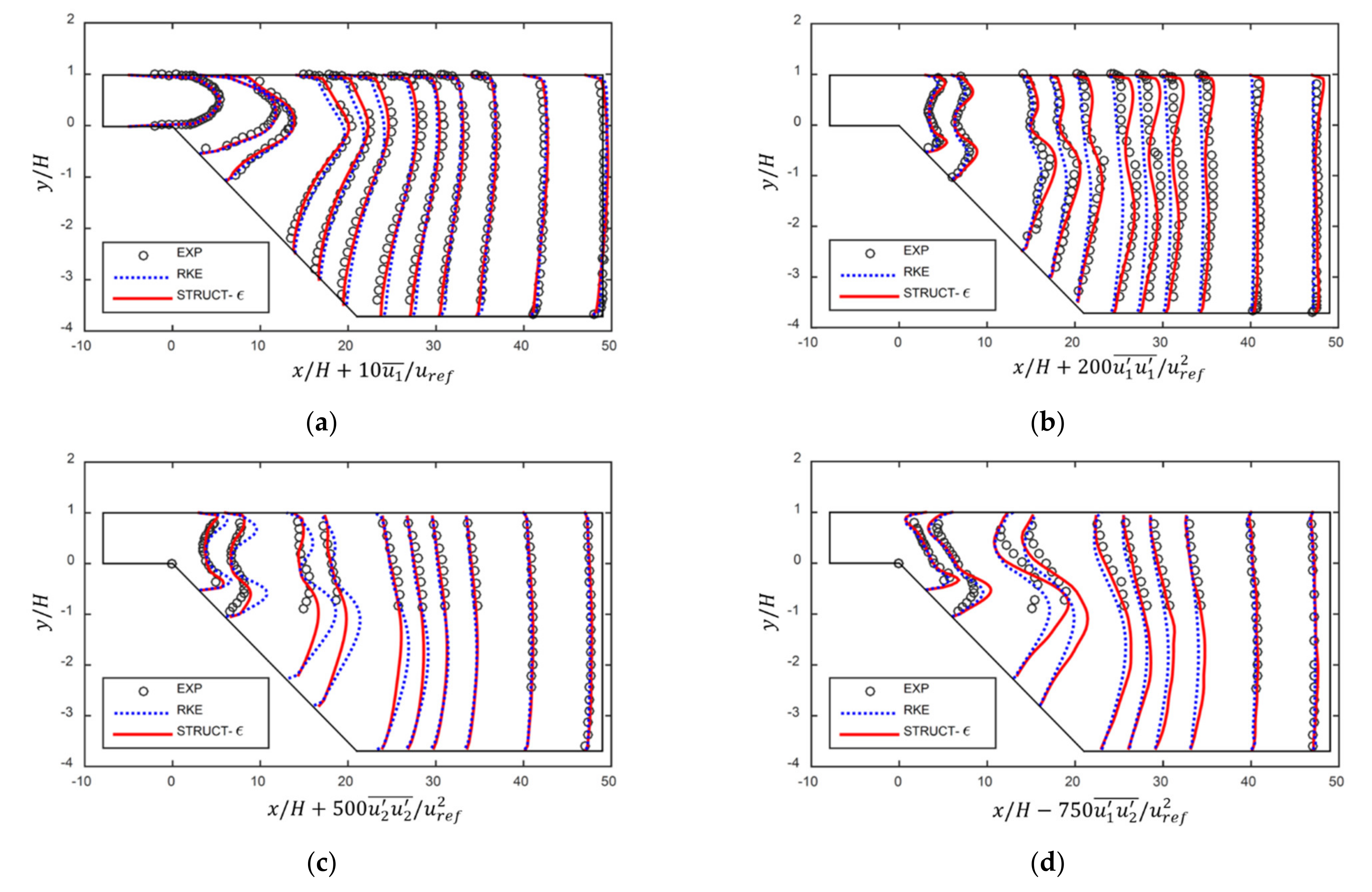
3.2. Flow in an Asymmetric Diffuser

The second test case models flow passing through an asymmetric diffuser, which has been widely adopted to evaluate the performance of hybrid turbulence models. This case is characterized by mild separation and reattachment, which has been demonstrated to be challenging for current hybrid models; the SAS model for example has been shown to massively fail on this configuration in the study by Davidson [33]. This section compares the prediction accuracy between the STRUCT- ε model, the Realizable k ε model and the experimental data obtained by Buice and Eaton [34].
The simulation domain reproduces the experimental configuration by Buice [34] where fully developed air flow enters a rectangular duct with 0.015 m height. The inlet Reynolds number is 20,000 based on the height ( H = 0.015 m) and the inlet velocity ( u ref = 18.32 m/s). Inlet boundary conditions adopt fully developed velocity, turbulent kinetic energy and turbulent dissipation rate profiles. Pressure outlet boundary conditions are applied on the outlet surface. All other surfaces adopt no-slip wall boundary conditions. In the diffuser section, there is a mild slope on the bottom wall and the angle is 10 degrees. This inclined wall reverts to being horizontal where the downstream domain height is greater than 4.7 times the inlet height. The configuration of the simulation domain is shown in Figure 4c. The mesh configuration is the same as that used by Lenci [9] with 1,795,200 cells in total. A convergence study was previously performed by Lenci for a URANS solution, confirming the appropriateness of the adopted mesh. The boundary layers are resolved on both the top and bottom walls, in order to accurately capture the separation point, and the y + value at the near wall cell centers is smaller than 1.0 in the whole domain.
Figure 4 compares the predicted streamline distribution for the RKE and STRUCT- ε models. As expected, the RKE model fails to predict the recirculation zone caused by the mild scale separation. In Figure 4b, a large recirculation region forms in the bottom corner for the STRUCT- ε models. The domain and shape of this recirculation is in agreement with the experimental results shown in Figure 4c. In Xu’s thesis [13], the predicted friction coefficients along the bottom and top walls of the asymmetric diffuser are compared against the experimental data. It is found that the bottom wall separation and reattachment positions predicted by the STRUCT- ε model are in close agreement with the experimental data while the RKE predicts much earlier separation and reattachment locations. For the skin friction on the top wall, the RKE model predicts flow separation which is not observed in the experiment. Although the STRUCT- ε model underpredicts the magnitude of skin friction, it captures the general trend of the experimental data and shows improvement over the RKE model.
Quantitative comparison of the mean velocities and Reynolds stresses profiles in the downstream location also confirm the appropriateness of the STRUCT- ε model as shown in Figure 5. Both the RKE and STRUCT- ε models show generally good agreement with the experimental data in terms of mean velocity, while the predictions of Reynolds stresses show large differences. The presented turbulent stresses include both the modeled and resolved parts in Figure 5. The RKE model fails to predict the flow unsteadiness and recirculation near the bottom corner; thus, the majority of the Reynolds stresses come from the modeled part. For the STRUCT- ε model, both the modeled and resolved part make important contributions to the Reynolds stress value. The predicted value of u 1 u 1 ¯ , u 1 u 2 ¯ and u 2 u 2 ¯ in the STRUCT- ε model shows a closer agreement with the experimental data while the RKE underpredicted the u 1 u 1 ¯ , u 1 u 2 ¯ in the expansion area.

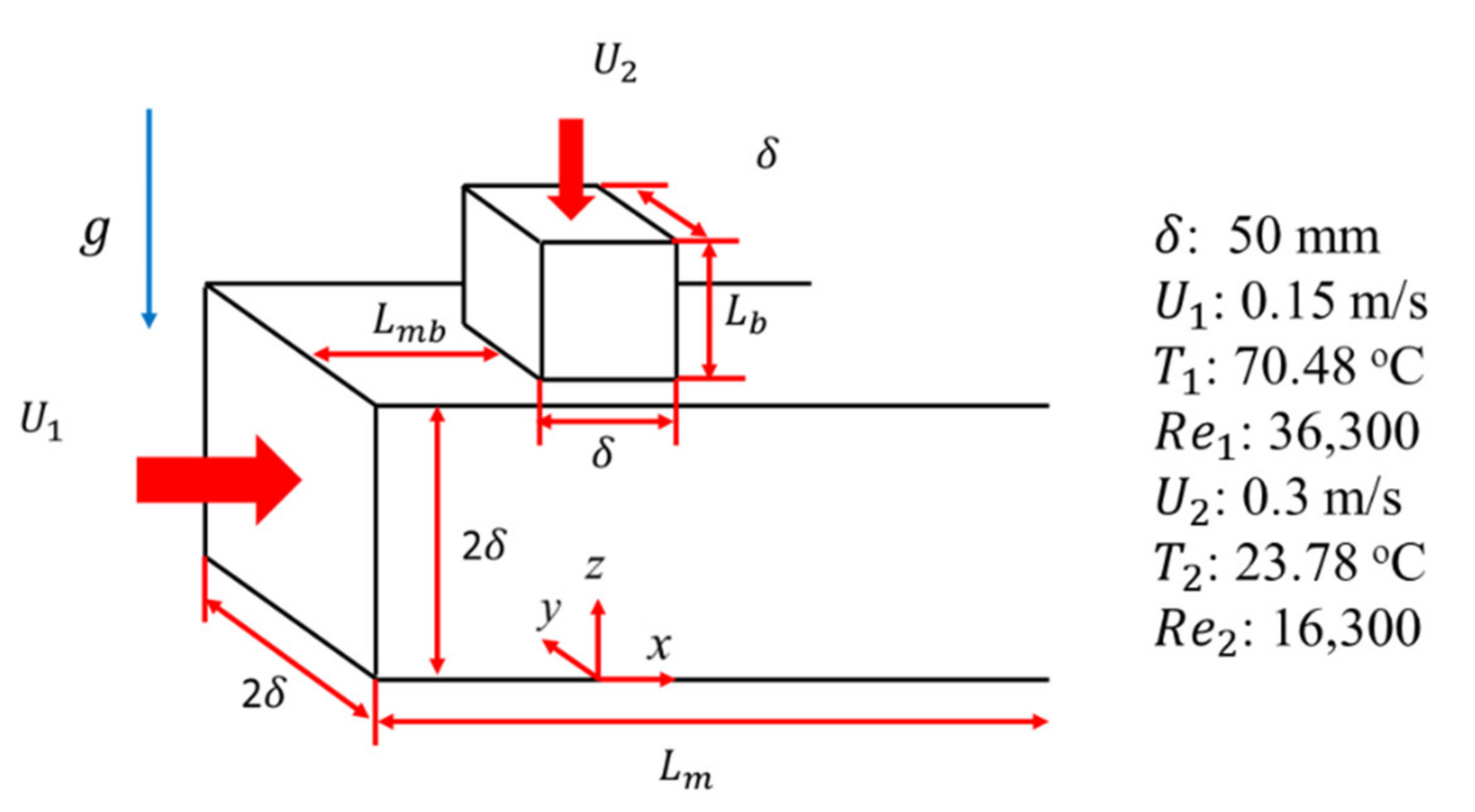
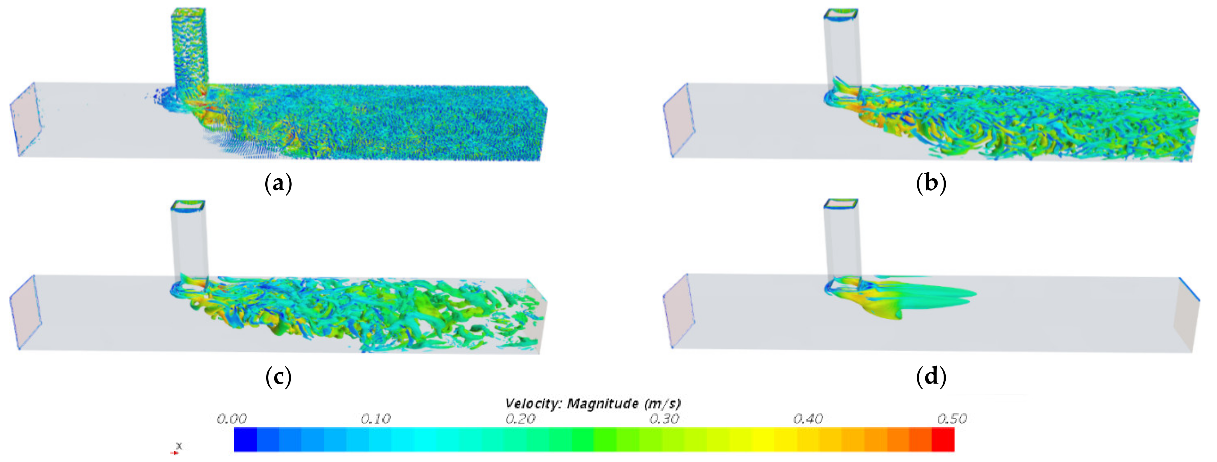
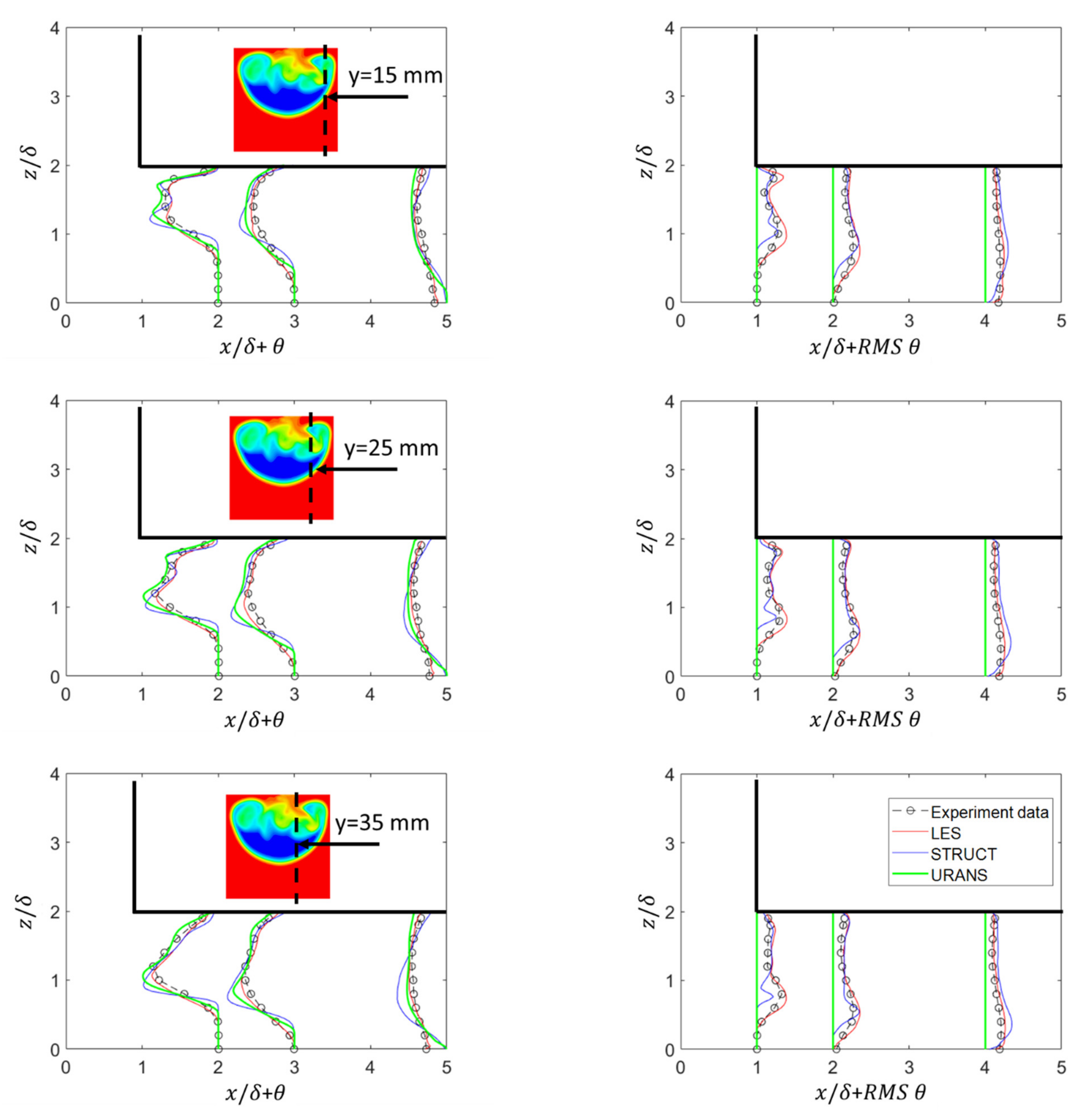
3.3. Thermal Mixing in T-Junction

The last test presented is the thermal mixing in a T-junction, which features large unsteady flow separation and has been the cause of components failure in nuclear plants operation. Accurate prediction of the thermal mixing in T-junctions is crucial, as an incomplete mixing process can generate large thermal fluctuations, which induces high cycle thermal fatigue on the pipe wall [35,36,37]. The OECD/NEA international benchmark exercise [2] provided a valuable assessment of turbulence modeling approaches and CFD codes for thermal mixing against the Vattenfall experimental data. Results confirmed the accuracy of the LES predictions, occupying the top 8 positions, out of 29 participants, for aggregate accuracy in velocity, temperature and spectral data. RANS-based approaches failed to predict both the velocity and temperature fields, due to their inability to account for the existence of unsteady coherent turbulent structures at the mixing location; two hybrid methods were tested, Delayed Detached Eddy Simulation (DDES) and SAS, and both failed to represent the flow accurately, with the SAS model providing overall the largest error among all submissions.
In this paper, thermal mixing in a T-junction is simulated with RKE, STRUCT- ε and LES models. The geometry is adopted from the experiments conducted by Mitsubishi Heavy Industries Ltd. (Tokyo, Japan) [38], which has been shown to be particularly challenging as a consequence of the adopted square sections [10,11]. Schematics and the flow conditions are given in Figure 6. Velocity and temperature fields were measured respectively using laser Doppler velocimetry (LDV) and thermocouples. Separate studies have been performed by Feng on this same flow configuration [10,11] and included a rigorous grid convergence study confirming the applicability of the mesh that is leveraged in the present simulations. The investigated flow condition has a temperature difference of 46.7 °C and the main and branch inlet Reynolds numbers are 36,300 and 16,300, respectively.
Figure 7 compares the resolved turbulent structures which are characterized by the Q-criterion contours [39]. Due to the velocity gradient between the main and branch inlets, large turbulent structures are generated when they mix in the T-junction. The LES solution resolves the majority of the turbulent structures, while the Realizable k ε model only resolves the largest structures in the mixing region. The STRUCT- ε model predicts a distribution of turbulent structures comparable to the LES results, while adopting the coarse mesh of the Realizable k ε model. Results from the STRUCT-T model are also included for comparison and show the ability of the STRUCT- ε implementation to further resolve the turbulent structures. The URANS model, as expected, overestimates the level of turbulent viscosity and cannot resolve the unsteadiness of the flow.
Figure 8 shows the evolution of the mean and RMS values of the dimensionless temperature field, θ , in the T-junction where θ is defined as ( T T 2 ) / ( T 1 T 2 ). Temperature fluctuations are damped near the bottom wall boundary, while they have the highest values in the regions where the hot and cold flows are encountered. The magnitude of temperature fluctuations decreases along the streamwise direction due to the thermal mixing. Using the same mesh configuration, both RKE and STRUCT- ε models are able to predict the mean temperature profiles while the RKE predicts practically no large temperature oscillations. The STRUCT- ε is able to quantify the temperature fluctuations appropriately and in close agreement with both the reference LES solution and the experimental data. The computational cost is reduced by approximately 95% from the LES simulations. Additionally, we note that the STRUCT- ε solution slightly delays the generation of structures as a consequence of the coarseness of the grid, which results in underprediction of the RMS values at the x / δ = 1 plane; this limitation can be reduced or eliminated by adopting a finer mesh resolution near the thermal mixing layers.

4. Conclusions

In this work the STRUCTure-based turbulent model, STRUCT- ε , is assessed for applicability to safety-related nuclear applications, with particular focus on flow oscillations that can lead to high-cycle mechanical and thermal fatigue failures. High fidelity resolution from the CFD predictions plays a fundamental role in evaluating the structural performance of reactor vessels and components and must be coupled to high computational efficiency to support the necessary uncertainty quantification. Three relevant test cases have been presented, flow over a periodic hill, flow through an asymmetric diffuser and thermal mixing in a T-junction, as they have been shown to be especially valuable to evaluate models’ performance, having previously demonstrated the failure of existing hybrid turbulence approaches.
The results produced by the STRUCT- ε model are compared against those from the widely adopted Realizable k ε model, reference LES solutions and experimental data. The hybridization strategy of the STRUCT- ε model demonstrates the ability to locally identify the areas of timescale overlap resulting in increased resolution of the turbulent structures and flow fluctuations. Results show that STRUCT- ε successfully predicts the flow separation, reattachment and turbulent unsteadiness in the case of flow over a periodic hill, as well as the recirculation zone in the asymmetric diffuser, which has been shown to challenge other hybrid turbulence methods. As shown on the T-junction validation case, the local activation allows all relevant turbulent structures in the flow to be resolved and provides optimal predictions for the temperature field, in close agreement with the experimental data and LES solution. As expected, the Realizable k ε model is able to provide acceptable predictions for the mean velocity and temperature fields but fails to resolve the flow unsteadiness due to the overpredicted turbulent viscosity implicit in its RANS formulation.
The presented results for the STRUCT- ε model have been produced on the same mesh configuration as the URANS results, with an increase in the computational cost by ~9.0%, which in contrast represents only 5% of the LES simulation time. Overall, the STRUCT model shows considerable promise in challenging safety-related flow scenarios, providing LES-like solutions at URANS-type computational cost. Future efforts will continue to extend the assessment of the approach with specific emphasis on thermal-related issues in advanced reactor designs, in combination with non-unity Prandtl number fluids, including both liquid metals and molten salts. The need for extension of the turbulent heat flux modelling will also be re-evaluated, being able to leverage the now considerably improved prediction of turbulent viscosity.

Author Contributions

Conceptualization, J.F., L.X. and E.B.; Data curation, J.F.; Formal analysis, J.F. and L.X.; Funding acquisition, E.B.; Investigation, J.F. and L.X.; Methodology, J.F., L.X. and E.B.; Project administration, E.B.; Software, J.F.; Supervision, E.B.; Validation, J.F.; Visualization, J.F.; Writing—original draft, J.F.; Writing—review & editing, J.F., L.X. and E.B. All authors have read and agreed to the published version of the manuscript.

Funding

This work was supported by Mitsubishi Heavy Industries Ltd. and the U.S. Department of Energy Nuclear Energy University Program (NEUP).

Acknowledgments

Koichi Tanimotob and Yoshiyuki Kondo from Mitsubishi Heavy Industries Ltd. provided valuable experimental data to support the study. The authors also greatly appreciate the help from Giancarlo Lenci.

Conflicts of Interest

The authors declare no conflict of interest.

References

  1. International Atomic Energy Agency. Use of Computational Fluid Dynamics Codes for Safety Analysis of Nuclear Reactor Systems, IAEA TECDOC-1379; IAEA: Vienna, Austria, 2003. [Google Scholar]
  2. Smith, B.L.; Mahaffy, J.H.; Angele, K. A CFD benchmarking exercise based on flow mixing in a T-junction. Nucl. Eng. Des. 2013, 264, 80–88. [Google Scholar] [CrossRef]
  3. Fröhlich, J.; von Terzi, D. Hybrid LES/RANS methods for the simulation of turbulent flows. Prog. Aerosp. Sci. 2008, 44, 349–377. [Google Scholar] [CrossRef]
  4. Speziale, C.G. Computing non-equilibrium turbulent flows with time-dependent RANS and VLES. In Fifteenth International Conference on Numerical Methods in Fluid Dynamics; Springer: Berlin/Heidelberg, Germany, 1997; pp. 123–129. [Google Scholar]
  5. Spalart, P.R. Detached-eddy simulation. Annu. Rev. Fluid Mech. 2009, 41, 181–202. [Google Scholar] [CrossRef]
  6. Girimaji, S. Partially-averaged Navier-Stokes model of turbulence: A Reynolds-averaged Navier-Storkes to direct numerical simulation bridging method. J. Appl. Mech. 2006, 73, 413–421. [Google Scholar] [CrossRef]
  7. Menter, F.; Kuntz, M.; Bender, R. A scale-adaptive simulation model for turbulent flow predictions. In Proceedings of the 41st Aerospace Sciences Meeting and Exhibit, Reno, Nevada, 6–9 January 2003; ARC: Reno, NV, USA, 2003; Volume 767, pp. 1–12. [Google Scholar]
  8. Menter, F.R.; Egorov, Y. A scale-adaptive simulation model using two-equation models. In Proceedings of the 43rd Aerospace Sciences Meeting and Exhibit, Reno, Nevada, 10–13 January 2005; ARC: Reno, NV, USA, 2005; Volume 1095, pp. 1–13. [Google Scholar]
  9. Lenci, G. A Methodology Based on Local Resolution of Turbulent Structures for Effective Modeling of Unsteady Flows. Ph.D. Thesis, Massachusetts Institute of Technology, Cambridge, MA, USA, 2016. [Google Scholar]
  10. Feng, J.; Baglietto, E.; Tanimoto, K.; Kondo, Y. Demonstration of the STRUCT turbulence model for mesh consistent resolution of unsteady thermal mixing in a T-junction. Nucl. Eng. Des. 2020, 361, 110572. [Google Scholar] [CrossRef]
  11. Feng, J.; Frahi, T.; Baglietto, E. STRUCTure-based URANS simulations of thermal mixing in T-junctions. Nucl. Eng. Des. 2018, 340, 275–299. [Google Scholar] [CrossRef]
  12. Acton, M.J.; Lenci, G.; Baglietto, E. Structure-Based Resolution of Turbulence for Sodium Fast Reactor Thermal Striping Applications. In Proceeding of the International Topical Meeting on Nuclear Reactor Thermal Hydraulics, Chicago, IL, USA, 30 August–4 September 2015. [Google Scholar]
  13. Xu, L. A Second Generation URANS Approach for Application to Aerodynamic Design and Optimization in the Automotive Industry. Ph.D. Thesis, Massachusetts Institute of Technology, Cambridge, MA, USA, 2020. [Google Scholar]
  14. Launder, B.E.; Spalding, D.B. The numerical computation of turbulent flows. Comput. Methods Appl. Mech. Eng. 1974, 3, 269–289. [Google Scholar] [CrossRef]
  15. Rehm, M.; Hatman, A.; Farges, B. Framatome’s unified single-phase CFD methodology for fuel design and analysis. In Proceedings of the CFD4NRS-8, Virtual Conference. 25–27 November 2020. [Google Scholar]
  16. Shih, T.-H.; Liou, W.W.; Shabbir, A.; Yang, Z.; Zhu, J. A new k-epsilon eddy viscosity model for high Reynolds number turbulent flows: Model development and validation. NASA Sti Recon Tech. Rep. N 1994, 95, 1442. [Google Scholar]
  17. Baglietto, E.; Ninokata, H. Anisotropic eddy viscosity modeling for application to industrial engineering internal flows. Int. J. Transp. Phenom. 2006, 8, 109. [Google Scholar]
  18. Baglietto, E.; Ninokata, H. A turbulence model study for simulating flow inside tight lattice rod bundles. Nucl. Eng. Des. 2005, 235, 773–784. [Google Scholar] [CrossRef]
  19. Feng, J.; Baglietto, E. Thermal Mixing Test for Struct Benchmark; Mitsubishi Heavy Industry, LTD: Tokyo, Japan, 2018. [Google Scholar]
  20. Feng, J.; Acton, M.; Baglietto, E.; Kraus, A.R.; Merzari, E. On the relevance of turbulent structures resolution for cross-flow in a helical-coil tube bundle. Ann. Nucl. Energy 2020, 140, 107298. [Google Scholar] [CrossRef]
  21. Launder, E.B.; Spaulding, B.D. Mathematical Models of Turbulence; Academic Press: London, UK, 1972. [Google Scholar]
  22. Nicoud, F.; Ducros, F. Subgrid-scale stress modelling based on the square of the velocity gradient tensor. Flow Turbul. Combust. 1999, 62, 183–200. [Google Scholar] [CrossRef]
  23. Smagorinsky, J. General circulation experiments with the primitive equations: I. The basic experiment. Mon. Weather Rev. 1963, 91, 99–164. [Google Scholar] [CrossRef]
  24. STAR-CCM+, Version 13.06; Siemens: Lebanon, NH, USA, 2018.
  25. Patankar, S.V.; Spalding, D.B. A calculation procedure for heat, mass and momentum transfer in three-dimensional parabolic flows. Int. J. Heat Mass Transf. 1972, 15, 1787–1806. [Google Scholar] [CrossRef]
  26. Patankar, S.V. Numerical Heat Transfer and Fluid Flow; Taylor & Francis: Abingdon, UK, 1980. [Google Scholar]
  27. Rhie, C.M.; Chow, W.L. Numerical study of the turbulent flow past an airfoil with trailing edge separation. AIAA J. 1983, 21, 1525–1532. [Google Scholar] [CrossRef]
  28. Venkatakrishnan, V. Convergence to Steady State Solutions of the Euler Equations on Unstructured Grids with Limiters. J. Comput. Phys. 1995, 118, 120–130. [Google Scholar] [CrossRef]
  29. Temmerman, M.; Leschziner, L. Large eddy simulation of separated flow in a channel with corrugated wall. In Proceedings of the Conference on Turbulence and Shear Flow, Stockholm, Sweden, 25–27 June 2001. [Google Scholar]
  30. Fröhlich, J.; Mellen, C.P.; Rodi, W.; Temmerman, L.; Leschziner, M.A. Highly resolved large-eddy simulation of separated flow in a channel with streamwise periodic constrictions. J. Fluid Mech. 2005, 526, 19–66. [Google Scholar] [CrossRef] [Green Version]
  31. ERCOFTAC Database. Univ. Manch. 2019. Available online: www.ercoftac.org (accessed on 29 August 2020).
  32. Mellen, C.P.; Fröhlich, J. Large eddy simulation of the flow over periodic hills. In Proceedings of the 16th IMACS World Congress, Lausanne, Switzerland, 21–25 August 2000. [Google Scholar]
  33. Davidson, L. Evaluation of the SST-SAS model: Channel flow, asymmetric diffuser and axi-symmetric hill. In Proceedings of the European Conference on Computational Fluid Dynamics, TU Delft, The Netherlands, 5–8 September 2006. [Google Scholar]
  34. Buice, C.U.; Eaton, J.K. Experimental Investigation of Flow through an Asymmetric Plane Diffuser. CTR Annu. Res. Briefs 1997, 1996, 243–248. [Google Scholar] [CrossRef] [Green Version]
  35. Lawn, C.J. The attenuation of temperature oscillations by liquid metal boundary l layers. Nucl. Eng. Des. 1977, 42, 209–222. [Google Scholar] [CrossRef]
  36. International Atomic Energy Agency. Validation of fast reactor thermomechanical and thermohydraulic codes. In IAEA Tecdoc-1318; International Atomic Energy Agency: Wien, Austria, 2002. [Google Scholar]
  37. Jungclaus, D.; Voswinkel, A.; Negri, P. Common IPSN/GRS safety assessment of primary coolant un-isolable leak incidents caused by stress cycling. In NEA-CSNI-R—1998-8; Nuclear Energy Agency: Paris, France, 1998. [Google Scholar]
  38. Fukushima, N.; Fukagata, K.; Kasagi, N.; Noguchi, H.; Tanimoto, K. Numerical and experimental study on turbulent thermal mixing in a T-junction flow. In Proceedings of the 6th ASME-JSME Thermal Engineering Joint Conference, Hawaii Island, HI, USA, 16–20 March 2003; pp. 16–20. [Google Scholar]
  39. Jeong, J.; Hussain, F. On the identification of a vortex. J. Fluid Mech. 1995, 285, 69–94. [Google Scholar] [CrossRef]
Figure 1. Schematics of the periodic hill (a) and the corresponding mesh configuration (b).
Fluids 06 00061 g001
Figure 2. Comparison of streamline distributions between Realizable k ε model (RKE) (a), STRUCT- ε (b) solutions and reference large eddy simulation (LES) data (c) [29] where red and blue vectors represent the high and low magnitude of velocity vectors.
Fluids 06 00061 g002
Figure 3. Comparison of (a) streamwise mean velocity profiles ( u 1 ¯ ), (b) transverse-normal mean velocity profiles ( u 2 ¯ ), (c) turbulent streamwise stress profiles ( u 1 u 1 ¯ ), (d) turbulent transverse-normal stress profiles ( u 2 u 2 ¯ ), between the RKE and STRUCT- ε models and the LES solution in the XY symmetry plane of the periodic hill geometry.
Fluids 06 00061 g003
Figure 4. Comparison of streamline distributions for the asymmetric diffuser obtained from (a) the RKE model, (b) the STRUCT- ε model and (c) the experimental observation [34] where red and blue colors represent high and low magnitude of the velocity vectors.
Fluids 06 00061 g004
Figure 5. Comparison of (a) mean streamwise velocity profiles, (b) streamwise turbulent stress profiles ( u 1 u 1 ¯ ), (c) transverse-normal turbulent stress profiles ( u 2 u 2 ¯ ), (d) turbulent shear stress profiles ( u 1 u 2 ¯ ), between the RKE and STRUCT- ε models and the experimental data [34] in the x y symmetry plane of the asymmetric diffuser.
Fluids 06 00061 g005
Figure 6. Geometry and flow conditions of the adopted T-junction mixing case.
Fluids 06 00061 g006
Figure 7. Instantaneous turbulent coherent structures (Q-criterion contours with value of 10) for LES (a), STRUCT- ε (b), STRUCT-T (c) and RKE (d) models. The contours are colored by velocity field.
Fluids 06 00061 g007
Figure 8. Comparison of development of mean (left column) and RMS (right column) dimensionless temperatures ( θ ) in the T-junction between STRUCT results, URANS results, LES solution and experimental data [38]. Top, middle and bottom rows represent the data collection at different transverse locations (15, 25 and 35 mm). Red and blue colors represent high and low fluid temperature.
Fluids 06 00061 g008
Publisher’s Note: MDPI stays neutral with regard to jurisdictional claims in published maps and institutional affiliations.

