Abstract
This paper is devoted to the analysis of the effect of gas injection on the efficiency of gaseous fuel burning. A coaxial burner with a perforated inner wall is presented in which the methane–air acceleration is observed. With the use of numerical analysis, it is demonstrated that the flame acceleration is related to the flow separation from the inner wall that, in turn, leads to the reduction in heat losses to the wall as well as to vortex formation and reduction in momentum losses. On the basis of the obtained results, a new technology of efficient burning of gaseous fuels can be proposed with the use of gas and/or liquid fuel injection.
1. Introduction
An important issue of contemporary combustion physics is the development of applied techniques for energy-efficient, safe, and clean utilization of different types of fuels. Although there is a clear progress in the development of alternative energetic materials, hydrocarbon fuels are still the most commonly used. Among particular problems of hydrocarbons burning are fuel supply, combustion mode control, and reduction of pollutant emissions. Here, one of the promising ways to provide energy-efficient and, at the same time, safe and clean combustion is to use compositions of different fuels or fuel blends with incombustible substances. Among the wide-spread approaches considered nowadays, there are blends of hydrocarbons with hydrogen [1,2,3,4]. For instance, blends of hydrogen with diesel and biodiesel fuels allow reducing emissions and increasing fuel conversion efficiencies [1,3]. Hydrogen addition to hydrocarbon fuels is also possible within nanobubbles that can significantly decrease fuel consumption levels and improve engine brake power [4]. At the same time, hydrogen addition, as well as the use of stoichiometric compositions of hydrocarbon fuels with air, leads not only to the more stable combustion but also to the intensification of emission of carbon and nitrogen oxides [5] under higher temperatures in the reaction zone. To reduce the temperature in the reaction zone, and thereby to inhibit the emission of harmful pollutants, two basic approaches can be considered. The first one is the chemical inhibition via the addition of less active hydrocarbon fuels or the utilization of lean compositions [6]. The second one is the organization of additional heat losses via the injection of water or emulsion droplets [7]. However, the use of both concepts leads to the instability of combustion modes [8]. That motivates further investigations of principally new approaches elaborated to achieve stable combustion modes with low emission.
One of the concepts considered nowadays for the maintenance of stable combustion of lean mixtures is the transfer of chemical and thermal energy from the combustion products to the fresh mixture in order to accelerate the initiation of chemical reactions and thereby to intensify the burning process [9]. Further, the catalysts can be used to reduce heat losses from the combustion zone to the channel wall. One of the leading mechanisms responsible for lean combustion stabilization is the exceeding of the adiabatic combustion temperature inside the reaction zone [10,11] that can be realized artificially via heat transfer from the combustion products to the fresh mixture [12]. The concentration combustibility limits can be extended due to an increase in the combustion temperature [13,14]. So, if one reduces the heat losses from the flame front, then the combustion stability will be maintained. Different approaches can be used to do this. Thus, for example, Sirignano et al. [15] proposes to use fuel film flowing down the channel wall. Under such conditions, the evaporation of the fuel and its burning in the near-wall region provide heat screening of the lean combustion zone. In turn, such a reduction in heat losses from the reaction zone determines the stable flame propagation. The liquid fuel-in-water emulsion can be injected through the porous element that would cause its foaming, and the combustible foam [16,17,18,19,20,21] will play the role of heat screen. In view of this, multiphase systems are of paramount interest for heat screening of lean flames. However, at the same time, it is also possible to utilize gaseous heat screens. As is shown in [22], gas injection into the flow through the porous wall can affect the temperature of the wall noticeably. Therefore, such an approach is suitable for the maintenance of stable combustion in low-reactive combustible mixtures, including lean mixtures. Besides, the gas injection causes flow perturbations that can promote the combustion process. Various aspects of flow-induced combustion enhancement and flame-vortex interactions are comprehensively discussed in the literature [23,24,25]. In a series of papers [26,27,28], Akkerman et al. have analyzed theoretically and numerically flame interactions with regular vortex patterns of relatively low amplitude. Such a system represents a model of weakly turbulent flow that can be established, for example, in a combustor with fuel inflow through perforated walls considered in the present paper. Bychkov et al. have conducted comprehensive theoretical research on the flame-turbulence and flame-vortex interactions and obtained fundamental results in that field, which were reflected in [29].
In this paper, an experimental setup is proposed to analyze the effect of gas injection into the reacting flow on the combustion mode of the low-reactive mixture. As an example, the methane–air mixture is considered. Obtained new experimental results illustrate the possible combustion intensification related to the gas injection. Detailed numerical analysis is carried out to understand the mechanisms of flame propagation mode under the considered conditions.
2. Problem Setup
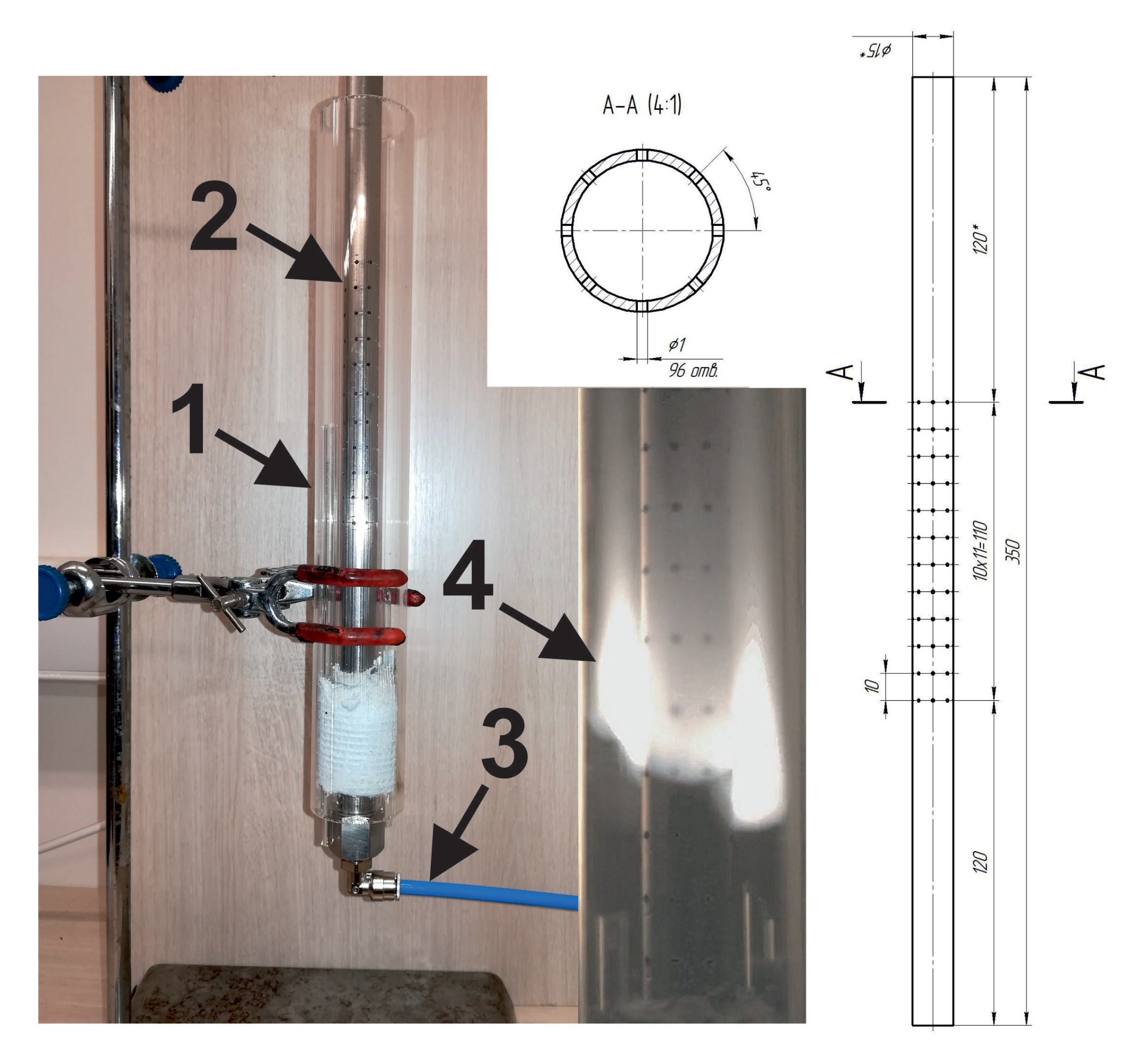
To study the effect of gas injection on the combustion mode let us consider the following problem setup. The combustible gas (stoichiometric methane–air mixture) is fed into the coaxial burner through the perforated inner wall (Figure 1) with the varying flow velocity. The ignition is initiated at the upper exit of the external tube by the pilot flame. Then, the flame is formed, it propagates downwards and interacts with the flow generated via gas injection through the wall. The experiments were conducted under normal ambient conditions. Methane and air (NIIKM Ltd., Moscow, Russia, 99.9% purity) were supplied into the inner channel of the coaxial reactor from the high-pressure vessels through the pressure valves and mass flow controllers (Bronkhorst EL-FLOW Prestige). The gases from two mass flow controllers were fed to the common gas line, where the methane–air mixture was formed and subsequently supplied to the inner channel. The flow rate was varied in the range from 1.1 L/min to 5.5 L/min. The flame propagation was registered with the use of the high-speed camera (Evercam 2000-8-C).
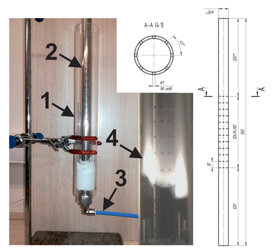
Figure 1.
Photography of the coaxial burner (1—outer channel made of glass, 2—inner steel channel with perforated wall, 3—feeding system), instant photo of the flame front (4) and scheme of the inner channel.
3. Numerical Methods
Two-dimensional axisymmetric calculations are carried out to get additional data for interpretation of the effect of gas injection on the combustion mode. The intensity of stoichiometric methane–air mixture combustion is moderate. The normal burning velocity of this compound is about 40 cm/s [30]. Flame propagation in the considered combustion system may be assumed as quasi-isobaric that opens up the possibility to neglect the compressibility effects by utilizing the low-Mach model. Low-Mach number approximation permits to partially bypass the restrictions imposed on the time step of integration by the explicit numerical technique implemented here that allows performing calculations on the larger spatial and temporal scales.
The combustion dynamics were modeled via the full Navier-Stokes system of the conservation laws in the low-Mach number approximation. Thermal conductivity, multicomponent diffusion, and energy release associated with the chemical transformations were taken into account. The solution was obtained for the following system of the governing equations [31]:
Here is the mass density, is the mass velocity vector, is the mass fraction of k-th component of gaseous mixture, is the molecular weight of k-th component of gaseous mixture, is the dynamic component of pressure fluctuations, which is much smaller by the order of magnitude compare with thermodynamic pressure and , is the viscous stresses tensor, is the stagnation energy per unit mass, is the vorticity vector, is the specific enthalpy of the mixture, is the specific enthalpy of k-th component of gaseous mixture, T is the temperature, is the thermal conductivity coefficient, is the viscosity coefficient, is the specific enthalpy of formation of k-th component of the gaseous mixture, is the diffusion velocity vector component of k-th specie, is the specific heat capacity at constant pressure of the mixture. Term represents the change in mass fraction of k-th specie due to the chemical reactions.
Isothermal boundary conditions with the temperature K are imposed on the solid boundaries of the computational domain. The governing Equations (1)–(7) were integrated via the second-order predictor/corrector method described in [32]. To perform mathematical modeling of low-Mach gasdynamics we implemented algorithms described in [32] in the in-house code, which was thoroughly tested and validated previously on a vast variety of gas dynamics and combustion problems [11,33]. The computational mesh cell size was equal to mm, the overall amount of cells was 45,000. Data form the JANAF tables [34] were used to calculate specific heat capacities and enthalpies of formation. Diffusion was modeled in the zeroth-order Hirshfelder-Curtiss approximation [35]. Mixture averaged transport coefficients were obtained from the first principles of the gas kinetics theory [36]. Correction velocity approach proposed in [37] was implemented to calculate diffusion velocities. Chemical kinetics of the stoichiometric methane–air mixture oxidation was modeled via two-step oxidation scheme 2S_CH4_BFER [38], which allows precise reproduction of the normal combustion velocity in the methane–air mixture in the wide pressure and composition range. According to [38], the 2S_CH4_BFER scheme considers two reactions:
Forward reaction rates are written as:
where is the pre-exponential factor, the activation energy, the temperature exponent of the reaction k and the reaction exponent for species j in reaction k. The subscript 1 denotes the methane oxidation reaction and subscript 2 denotes CO-CO2 equilibrium reactions. The reaction parameters are taken from [38].
4. Results and Discussion
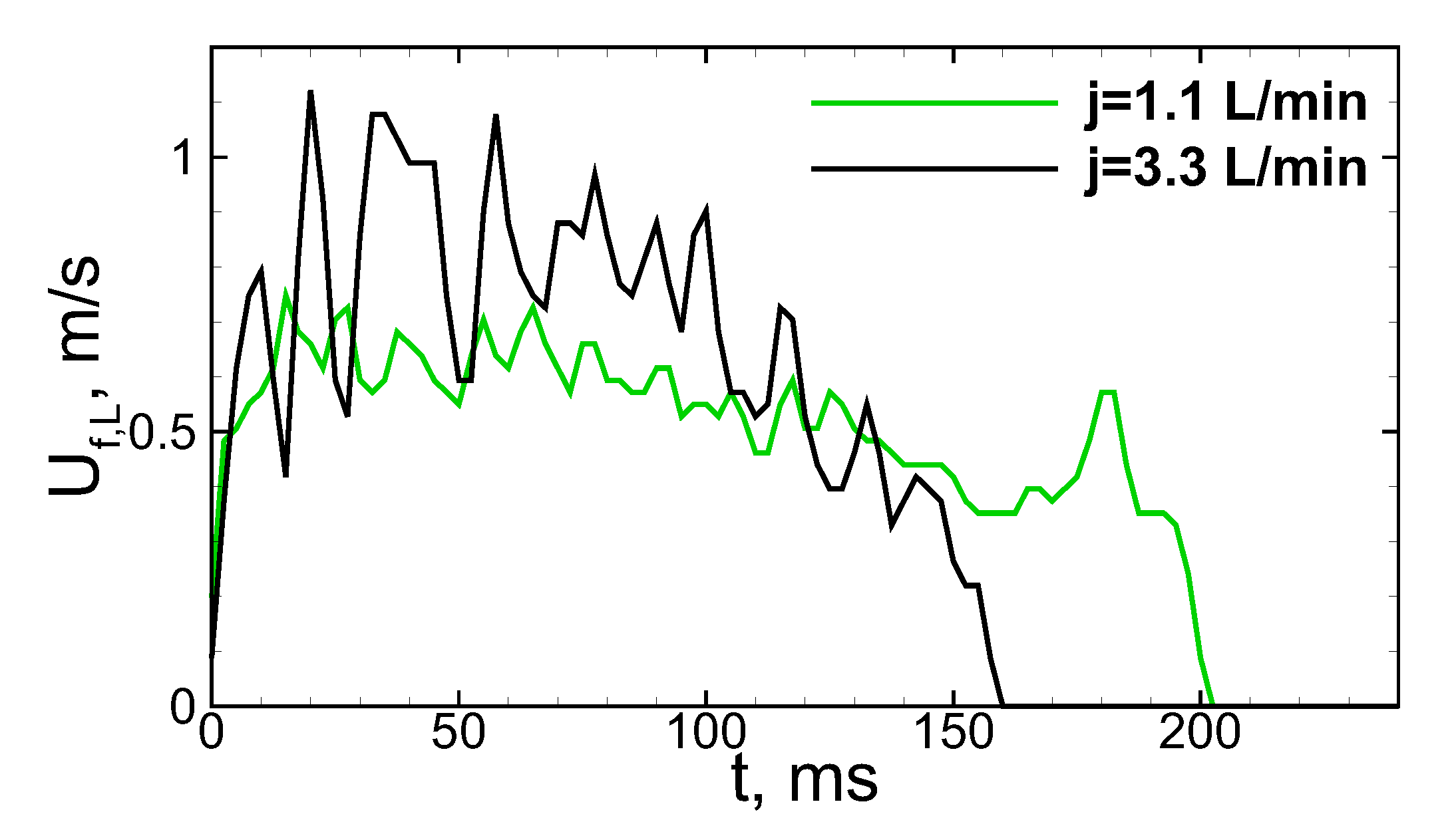
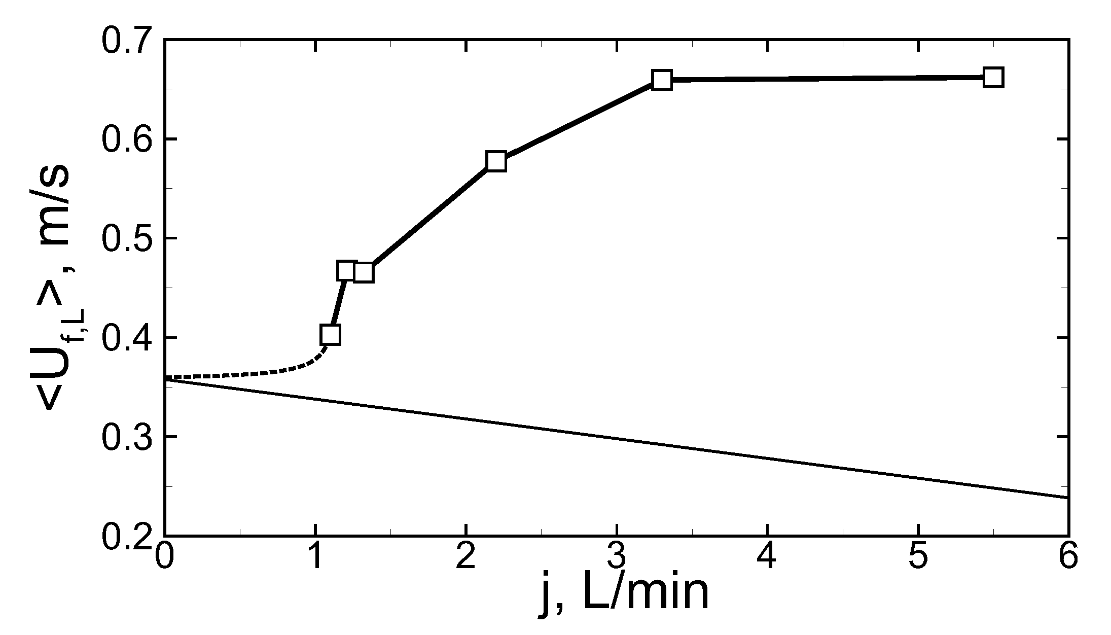
After ignition at the upper exit of the coaxial burner, a combustion wave is formed and propagates downwards. Herewith, the mode of flame propagation occurs to be non-steady, as it can be seen from the analysis of the typical history of the flame speed along the burner length (Figure 2). The value of was obtained as time derivative of the trajectory of the flame front leading point. First of all, one can observe the non-monotonic behavior of the flame speed that illustrates that the flame propagates in an oscillating mode. Herewith, the average flame speed occurs to be higher than one expected for a single-chamber burner in which the flame speed in the laboratory reference frame can be calculated as a sum of the burning rate () and flow velocity (u): . In the quiescent mixture, flame speed equals the normal burning rate, while in the burner with the counter-flow the flame speed usually should be lower and turns to be equal to zero when the counter-flow speed equals the normal burning rate by its absolute value (). Numerical analysis of the flow through the burner shows that there is a certain reduction in the counter-flow velocity after flowing through the perforated wall between the inner channel where the mixture is fed and the outer channel where the mixture is ignited (Figure 1). The factor by which the counter flow velocity is reduced for stoichiometric methane–air mixture equals 5.3. Thus, for example, in the case of the flow rate of 5.5 L/min the gas velocity at the entrance of the inner channel equals 0.59 m/s, while at the exit of the outer channel, it equals 0.11 m/s. Under such conditions, the flame speed can be estimated via as 0.25 m/s, while the average value of the flame speed along the burner equals 0.66 m/s in the experiment. So there is an obvious acceleration of the combustion process in the considered burner. Figure 3 illustrates the dependence of the average flame speed on the flow rate in the range from 1.1 to 5.5 L/min. Thin line represents the estimation according to the formula . So, one can observe the permanent increase in the flame speed with the flow rate in the whole considered range of the flow rates.
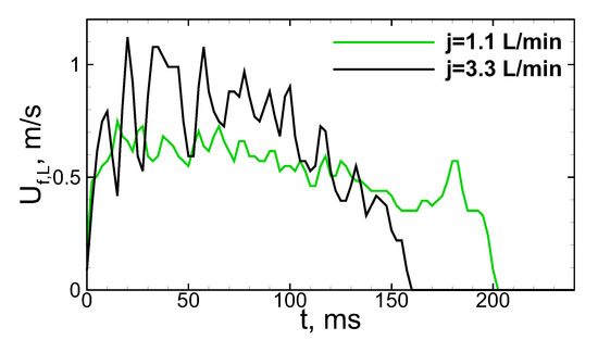
Figure 2.
Experimentally obtained histories of the flame speed in a laboratory reference frame for two different flow rates.
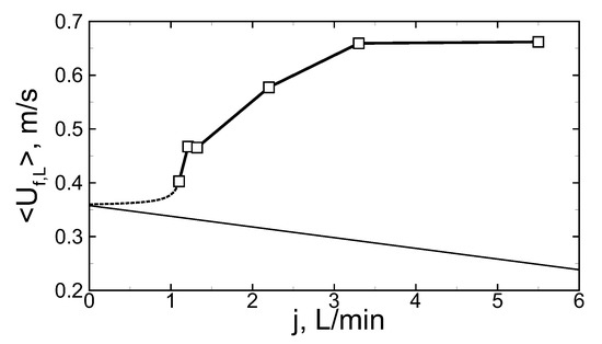
Figure 3.
Dependence of flame speed averaged over the channel length on the flow rate. Signs—experimental data. Dashed line—approximation with account of normal burning rate value (at ). Thin solid line—estimation of the flame speed in one-dimensional approximation.
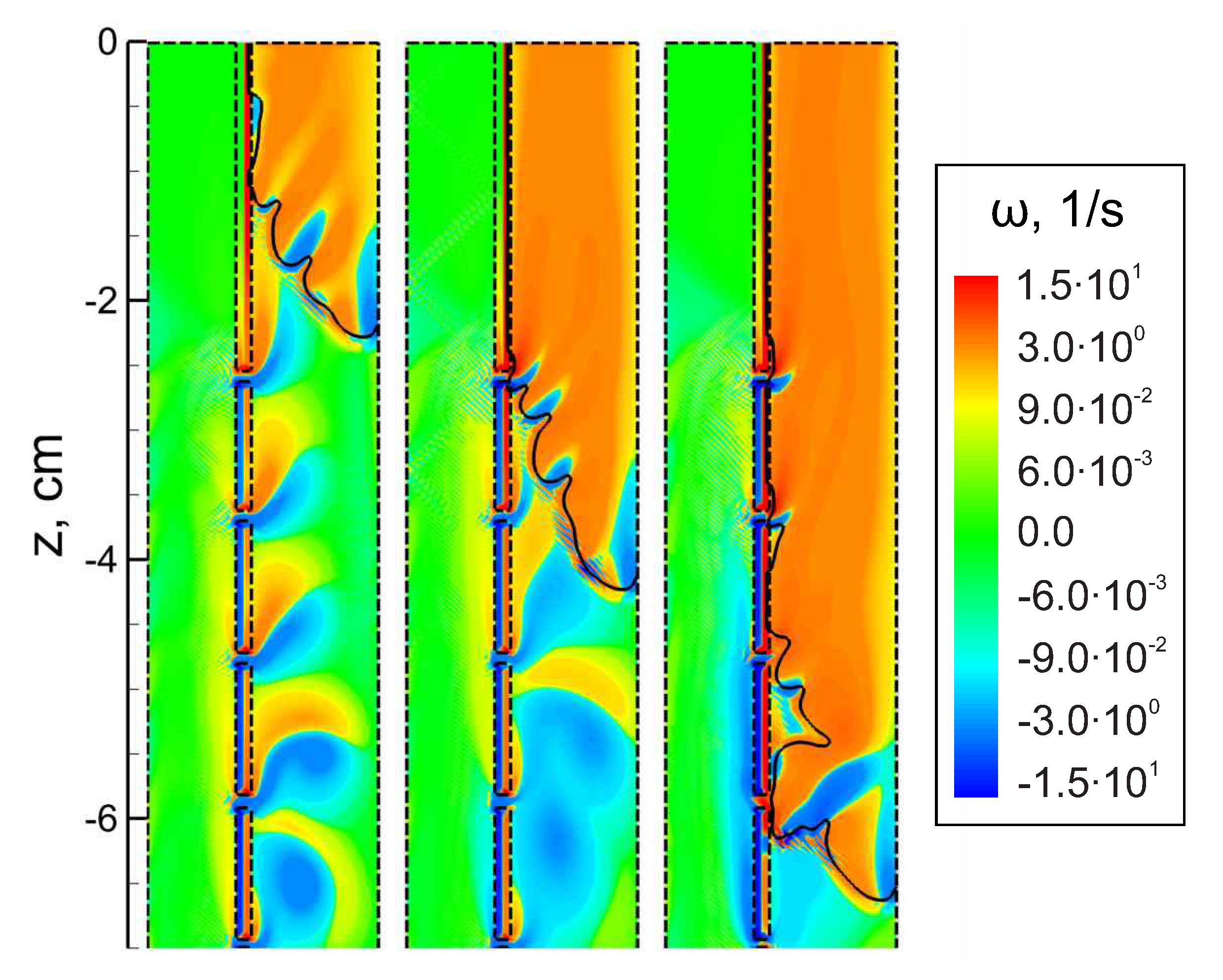
Let us now consider the possible causes of the observed behavior of the flame in the considered coaxial burner. As it was shown recently in [22], the important roles in the heat transfer near the porous (or perforated) wall belong both to the dissipation of kinetic energy and convective heat transfer in the formed boundary layer. In view of this, the flow separation from the perforated wall due to the gas injection defines the specific mode of heat transfer to the wall. In particular, the formed boundary layer screens the bulk flow from the heat losses to the wall. Under such conditions, there is a certain reduction of heat losses from the flame front that makes it more stable even inside a relatively narrow channel. The vortices formed in the channel due to the gas injection affect the flame propagation as well, as the numerical analysis of the flow indicates. The intensity of these vortices is relatively low, so the perturbed flame surface maintains its continuity. However, at the same time, it occurs to be stretched. That determines the combustion intensification related to the increase in the flame surface. As a result, one can observe local flame acceleration in the region of flame-vortex interaction. Such an interaction is demonstrated in Figure 4, where the results of numerical simulations are presented for the case of the flow rate equal to 5.5 L/min.
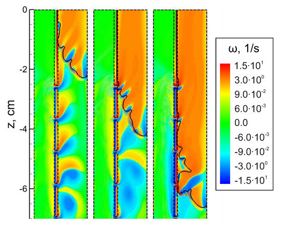
Figure 4.
Calculated vorticity field in the coaxial burner at subsequent time instants (from left to right: at 70 ms, 120 ms and 170 ms after ignition). Vorticity is defined as . Solid lines—flame front, dashed lines—boundaries of the calculation domain. corresponds to the upper exit of the burner.
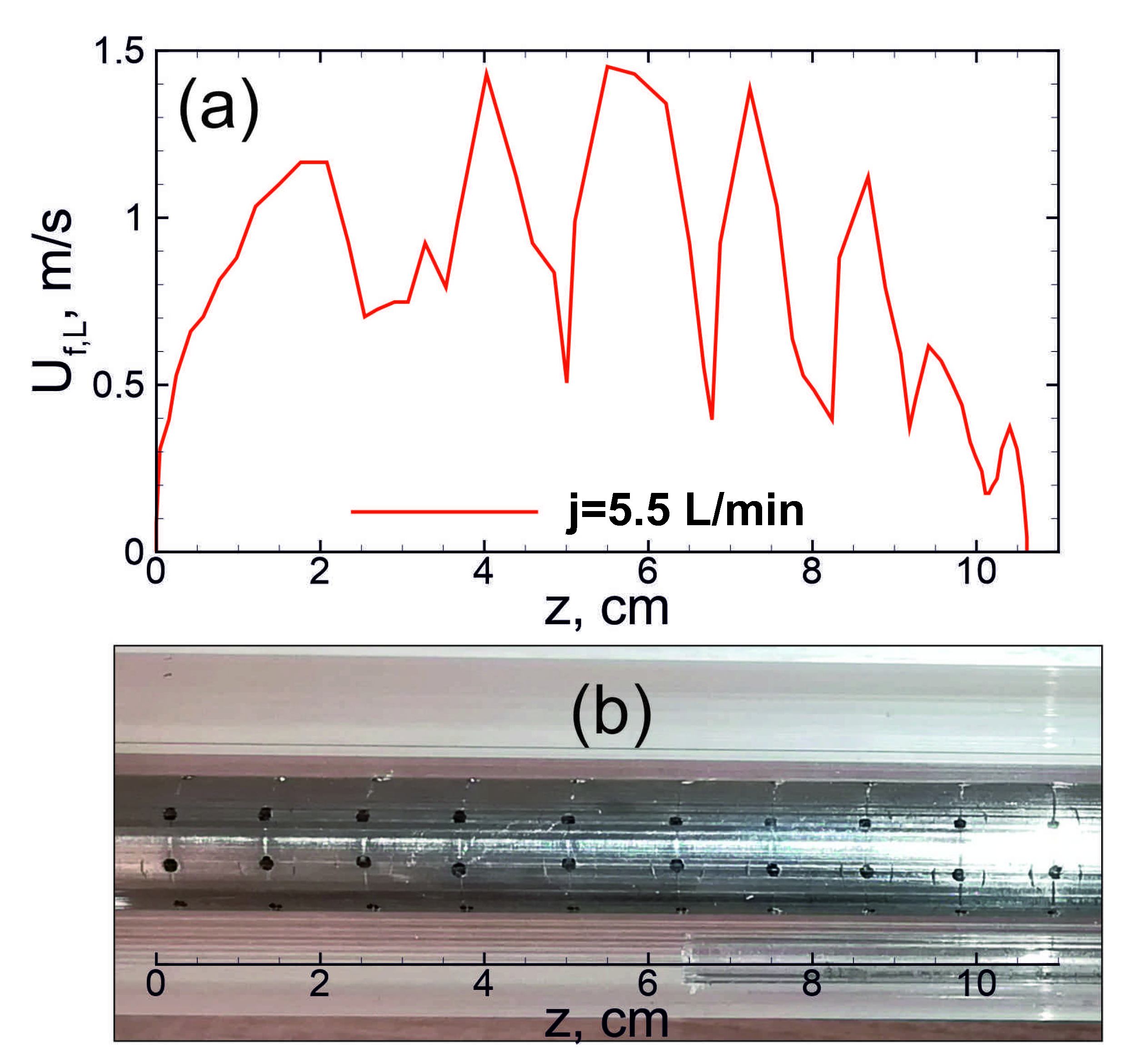
The performed calculations demonstrate only single flame-to-vortex interaction that is related to certain limitations of two-dimensional axisymmetric problem setup. These limitations are associated primarily with the lower dimensionality and approximate model of the flow through the round holes in the inner wall, and one should expect a more complex flow pattern related to the jet-like gas injection in reality. Every hole represents a source of vorticity, so the process of flame propagation through the outer channel can be considered as an interaction of propagating flame with a vortex street. Such a behavior of the flame can be observed in a more pronounced way at the high intensity of the flow. Thus, for example, at a high flow rate, the oscillations of the flame speed occur to be quite regular and correlate with the positions of holes (Figure 5). The flow pattern is qualitatively similar to that considered in [26,27], where several vortices were evenly distributed along the closed tube volume. Numerical analysis performed in [26] shows that the regular pattern of vortices distributed in the combustion chamber can sufficiently increase the flame propagation intensity and reduce the burn-out time. Herewith, the intensity of vortical flow determines the acceleration of the burn-out process that is consistent with the flame acceleration at the rising flow rate depicted in Figure 3.
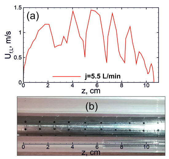
Figure 5.
(a) Experimentally obtained history of the flame speed along the channel length at flow rate of 5.5 L/min and (b) corresponding position of the holes in the wall of inner channel.
The obtained results illustrate the effect of the gas injection on the flame behavior and consequently on the efficiency of the burning process inside the burner operating on the gaseous fuel. The phenomenon of accelerated flame propagation under the effect of gas injection through the perforated wall can be used in different technical systems to improve the efficiency of the burning process and/or to reduce the emission of harmful pollutants. With the use of a gas injection system, one can improve the stability of the burning process when using slowly-reacting mixtures, including lean mixtures characterized by the relatively low temperature of combustion products and thereby low emissions of harmful pollutants. As well, it is promising to inject multiphase mixtures containing, for example, liquid droplets to reduce the temperature of the combustion products in the vessel. At the same time, the effects discussed above should keep the flame stable, reducing the heat losses on the shell of the reactor.
5. Conclusions
In this paper, a new concept of flame stabilization via gas injection into the pre-flame zone is discussed. Gas injection is realized in a coaxial burner with a perforated wall between inner and outer channels. The experimental results for stoichiometric methane–air mixture indicate stable flame propagation in such a system with an average flame speed greater than the normal burning rate that in turn indicates the mechanism of flame acceleration. In particular, this mechanism is related to the flow separation from the wall by the injected gas and therefore to the certain reduction in the heat losses to the wall. At the same time, there is a vorticity generation in the bulk flow due to the gas injection. As a result, the perturbed flame accelerates due to the flame-vortex interactions. The proposed concept is recommended for utilization in novel technical systems in order to improve the stability and energy efficiency of the slowly-reacting mixtures combustion. In turn, this opens the possibility to reduce emissions of harmful pollutants.
Author Contributions
Conceptualization, A.K. (Alexey Kiverin) and B.K.; methodology, A.K. (Alexey Kiverin), B.K., V.G. and A.K. (Alexey Korshunov); software, I.Y.; validation, I.Y., A.Y.; formal analysis, A.K. (Alexey Kiverin), B.K.; investigation, A.K. (Alexey Kiverin), B.K., V.G., A.K. (Alexey Korshunov), I.Y. and A.Y.; resources, V.G. and I.Y.; data curation, V.G., A.K. (Alexey Korshunov), B.K., I.Y.; writing—original draft preparation, A.K. (Alexey Kiverin); writing—review and editing, A.K. (Alexey Kiverin) and I.Y.; visualization, A.K. (Alexey Kiverin) and I.Y.; supervision, A.K. (Alexey Kiverin); project administration, A.K. (Alexey Kiverin); funding acquisition, A.K. (Alexey Kiverin). All authors have read and agreed to the published version of the manuscript.
Funding
We acknowledge high-performance computing support from the Joint Supercomputer Center of the Russian Academy of Sciences and Supercomputing Center of Lomonosov Moscow State University.
Conflicts of Interest
The authors declare no conflict of interest.
Abbreviations
The following abbreviations are used in this manuscript:
| JANAF | Joint Army, Navy and Air Force |
References
- Senthil Kumar, M.; Ramesh, A.; Nagalingam, B. Use of hydrogen to enhance the performance of a vegetable oil fuelled compression ignition engine. Int. J. Hydrogen Energy 2003, 28, 1143–1154. [Google Scholar] [CrossRef]
- Aggarwal, S.; Awomolo, O.; Akber, K. Ignition characteristics of heptane–hydrogen and heptane–methane fuel blends at elevated pressures. Int. J. Hydrogen Energy 2011, 36, 15392–15402. [Google Scholar] [CrossRef]
- Ji, C.; Wang, S.; Zhang, B. Performance of a hybrid hydrogen–gasoline engine under various operating conditions. Appl. Energy 2012, 97, 584–589. [Google Scholar] [CrossRef]
- Oh, S.H.; Yoon, S.H.; Song, H.; Han, J.G.; Kim, J.M. Effect of hydrogen nanobubble addition on combustion characteristics of gasoline engine. Int. J. Hydrogen Energy 2013, 38, 14849–14853. [Google Scholar] [CrossRef]
- Ilbas, M.; Yilmaz, I.; Kaplan, Y. Investigations of hydrogen and hydrogen–hydrocarbon composite fuel combustion and emission characteristics in a model combustor. Int. J. Hydrogen Energy 2005, 30, 1139–1147. [Google Scholar] [CrossRef]
- Shudo, T.; Omori, K.; Hiyama, O. NOx reduction and NO2 emission characteristics in rich-lean combustion of hydrogen. Int. J. Hydrogen Energy 2008, 33, 4689–4693. [Google Scholar] [CrossRef]
- Huo, M.; Lin, S.; Liu, H.; Lee, C.F.F. Study on the spray and combustion characteristics of water–emulsified diesel. Fuel 2014, 123, 218–229. [Google Scholar] [CrossRef]
- Pelce, P.; Clavin, P. Influence of hydrodynamics and diffusion upon the stability limits of laminar premixed flames. J. Fluid Mech. 1982, 124, 219. [Google Scholar] [CrossRef]
- Ju, Y.; Maruta, K. Microscale combustion: Technology development and fundamental research. Prog. Energy Combust. Sci. 2011, 37, 669–715. [Google Scholar] [CrossRef]
- Yakovenko, I.S.; Ivanov, M.F.; Kiverin, A.D.; Melnikova, K.S. Large-scale flame structures in ultra-lean hydrogen-air mixtures. Int. J. Hydrogen Energy 2018, 43, 1894–1901. [Google Scholar] [CrossRef]
- Volodin, V.V.; Golub, V.V.; Kiverin, A.D.; Melnikova, K.S.; Mikushkin, A.Y.; Yakovenko, I.S. Large-scale Dynamics of Ultra-lean Hydrogen-air Flame Kernels in Terrestrial Gravity Conditions. Combust. Sci. Technol. 2020. [Google Scholar] [CrossRef]
- Jones, A.R.; Lloyd, S.A.; Weinberg, F.J. Combustion in heat exchangers. Proc. R. Soc. Lond. A. Math. Phys. Sci. 1978, 360, 97–115. [Google Scholar] [CrossRef]
- Ronney, P. Analysis of non-adiabatic heat-recirculating combustors. Combust. Flame 2003, 135, 421–439. [Google Scholar] [CrossRef]
- Ju, Y.; Choi, C. An analysis of sub-limit flame dynamics using opposite propagating flames in mesoscale channels. Combust. Flame 2003, 133, 483–493. [Google Scholar] [CrossRef]
- Sirignano, W.A.; Pham, T.K.; Dunn-Rankin, D. Miniature-scale liquid-fuel-film combustor. Proc. Combust. Inst. 2002, 29, 925–931. [Google Scholar] [CrossRef]
- Kichatov, B.; Korshunov, A.; Kiverin, A.; Son, E. Foamed emulsion—Fuel on the base of water-saturated oils. Fuel 2017, 203, 261–268. [Google Scholar] [CrossRef]
- Kichatov, B.; Korshunov, A.; Kiverin, A.; Son, E. Methods for Regulation of Flame Speed in the Foamed Emulsion. Combust. Sci. Technol. 2017, 189, 2095–2114. [Google Scholar] [CrossRef]
- Kichatov, B.; Korshunov, A.; Kiverin, A.; Son, E. Experimental study of foamed emulsion combustion: Influence of solid microparticles, glycerol and surfactant. Fuel Process. Technol. 2017, 166, 77–85. [Google Scholar] [CrossRef]
- Kichatov, B.; Korshunov, A.; Kiverin, A.; Ivanov, M. Effect of ultrasonic emulsification on the combustion of foamed emulsions. Fuel Process. Technol. 2018, 169, 178–190. [Google Scholar] [CrossRef]
- Kichatov, B.; Korshunov, A.; Kiverin, A.; Saveliev, A. The role of explosive boiling in the process of foamed emulsion combustion. Int. J. Heat Mass Transf. 2018, 119, 199–207. [Google Scholar] [CrossRef]
- Kichatov, B.; Korshunov, A.; Kiverin, A.; Son, E. Combustion of hydrogen–oxygen microfoam on the water base. Int. J. Hydrogen Energy 2017, 42, 16866–16876. [Google Scholar] [CrossRef]
- Leontiev, A.; Saveliev, A.; Kichatov, B.; Kiverin, A.; Korshunov, A.; Sudakov, V. Effect of gaseous coolant temperature on the transpiration cooling for porous wall in the supersonic flow. Int. J. Heat Mass Transf. 2019, 142, 118433. [Google Scholar] [CrossRef]
- Renard, P.H.; Thévenin, D.; Rolon, J.; Candel, S. Dynamics of flame/vortex interactions. Prog. Energy Combust. Sci. 2000, 26, 225–282. [Google Scholar] [CrossRef]
- Kadowaki, S.; Hasegawa, T. Numerical simulation of dynamics of premixed flames: Flame instability and vortex—Flame interaction. Prog. Energy Combust. Sci. 2005, 31, 193–241. [Google Scholar] [CrossRef]
- Searby, G.; Clavin, P. Weakly Turbulent, Wrinkled Flames in Premixed Gases. Combust. Sci. Technol. 1986, 46, 167–193. [Google Scholar] [CrossRef]
- Akkerman, V.; Bychkov, V.; Eriksson, L.E. Numerical study of turbulent flame velocity. Combust. Flame 2007, 151, 452–471. [Google Scholar] [CrossRef]
- Akkerman, V.B.; Bychkov, V.V.; Bastiaans, R.J.M.; de Goey, L.P.H.; van Oijen, J.A.; Eriksson, L.E. Flow-flame interaction in a closed chamber. Phys. Fluids 2008, 20, 055107. [Google Scholar] [CrossRef]
- Akkerman, V.; Ivanov, M.; Bychkov, V. Turbulent Flow Produced by Piston Motion in a Spark-ignition Engine. Flow Turbul. Combust. 2009, 82, 317–337. [Google Scholar] [CrossRef]
- Bychkov, V.; Petchenko, A.; Akkerman, V. Increase of the flame velocity in a rotating gas and the renormalization approach to turbulent burning. Combust. Sci. Technol. 2007, 179, 1231–1259. [Google Scholar] [CrossRef]
- Bradley, D.; Hundy, G. Burning velocities of methane–air mixtures using hot-wire anemometers in closed-vessel explosions. Symp. Int. Combust. 1971, 13, 575–583. [Google Scholar] [CrossRef]
- Kuo, K.K.; Acharya, R. Fundamentals of Turbulent and Multiphase Combustion, 1st ed.; John Wiley & Sons, Inc.: Hoboken, NJ, USA, 2012. [Google Scholar]
- McGrattan, K.; McDermott, R.; Hostikka, S.; Floyd, J.; Vanella, M. Fire Dynamics Simulator Technical Reference Guide Volume 1: Mathematical Model. In Technical Report NIST Special Publication 1018-1; U.S. Department of Commerce, National Institute of Standards and Technology: Gaithersburg, MD, USA, 2019. [Google Scholar] [CrossRef]
- Bykov, V.; Kiverin, A.; Koksharov, A.; Yakovenko, I. Analysis of transient combustion with the use of contemporary CFD techniques. Comput. Fluids 2019, 194, 104310. [Google Scholar] [CrossRef]
- Chase, M.W. Data Reported in NIST Standard Reference Database 69, June 2005 Release: NIST Chemistry WebBook. J. Phys. Chem. Ref. Data Monogr. 1998, 9, 1–1951. [Google Scholar]
- Hirschfelder, J.O.; Curtiss, C.F.; Bird, R.B. The Molecular Theory of Gases and Liquids, Revised ed.; Wiley-Interscience: Hoboken, NJ, USA, 1964. [Google Scholar]
- Kee, R.J.; Coltrin, M.E.; Glarborg, P. Chemically Reacting Flow: Theory and Practice, 1st ed.; Wiley-Interscience: Hoboken, NJ, USA, 2003. [Google Scholar]
- Coffee, T.; Heimerl, J. Transport algorithms for premixed, laminar steady-state flames. Combust. Flame 1981, 43, 273–289. [Google Scholar] [CrossRef]
- Franzelli, B.; Riber, E.; Gicquel, L.Y.; Poinsot, T. Large Eddy Simulation of combustion instabilities in a lean partially premixed swirled flame. Combust. Flame 2012, 159, 621–637. [Google Scholar] [CrossRef]
Publisher’s Note: MDPI stays neutral with regard to jurisdictional claims in published maps and institutional affiliations. |
© 2021 by the authors. Licensee MDPI, Basel, Switzerland. This article is an open access article distributed under the terms and conditions of the Creative Commons Attribution (CC BY) license (http://creativecommons.org/licenses/by/4.0/).

