1. Introduction
Polymeric products are widely used in different application areas such as medical, packaging, civil construction, commodities, energy, etc., playing a crucial role in our daily life. Understanding their complex rheological behavior is essential for quality assurance and productivity maximisation purposes. Accordingly, polymers have been dealt with in several studies from the past decades, aiming at their rheological characterisation and modelling. Generally, the rheological characterisation of polymer systems is divided into two different approaches, according to the type of flow to be characterised (and used), which can be shear and extensional. When subjected to a shear flow, polymer melts exhibit a shear-thinning behavior, i.e., they are pseudoplastic fluids, which means that their shear viscosity decreases as the shear rate is increased. In an ideal extensional flow, the deformation is measured as a response to the extensional stresses (normal stresses) applied, or vice versa. In this type of flow, polymer melts generally exhibit a strain-hardening behavior, being dilatant fluids [
1], meaning that their extensional viscosity increases with increasing extensional strain rate.
Based on the research history on polymer systems rheology, shear flows were the most commonly addressed. Accordingly, numerous studies were published; thus, the subject is well documented [
2,
3]. On the other hand, viscometric extensional flows are difficult to achieve [
4], and/or interpretation of experimental data is complex. As a consequence, there is a little commercial offer of extensional rheometers, and most of the knowledge about the materials is related to shear flow characterisation [
5]. However, extensional flows are dominant in some relevant polymer processing technologies such as blow-molding, fiber-spinning, thermoforming, film-blowing, and coating. Therefore, in these cases the optimisation of both the operating conditions and products requires proper characterisation of polymer melt extensional properties. The main investigations about extensional flow started in the late 1960s [
6,
7,
8,
9,
10,
11], although the topic was introduced earlier by Trouton in 1906 [
12], and few papers were published in the late 1930s [
13,
14]. At that time, the platform used to perform the extensional rheometry tests (tensile tester) showed several limitations. These led to the development of new platforms aimed at facilitating test performance. In the first attempt, Cogswell [
15] used a stress-controlled platform, which later was improved by Münstedt [
16]. In this device, a load is applied to the sample, and the length evolution along time is measured. In this way, the extensional viscosity was calculated based on the variation in the sample length. The proposed approach was considerably difficult to apply.
Aiming at facilitating the measurement process, as well as ensuring accurate data, various testing platforms, mainly developed for the characterisation of uniaxial extensional flows, were proposed. Raible et al. [
17] presented a type of platform based on the rotary clamp technique, which later became known as the Meissner-type rheometer. In this platform, a sample immersed in an oil bath is stretched horizontally at a constant extensional rate. Although the oil bath helps to eliminate the sagging (gravity effect), especially for low viscosity materials, it might affect the results due to eventual physical-chemical interactions with the sample. On the other hand, contrarily to the tensile tester platform [
18], a constant extensional rate was imposed by a constant rotational velocity of the gears (clamps). Furthermore, using two sets of rotary clamps with equal rotation velocity provided a homogeneous sample stretching, eliminating necking near the clamps. Later, the Rheometrics Melt Extensometer (RME) platform, which is the modified and commercialised version of the Meissner-type rheometer, was presented by Meissner and Hostettler [
19]. Here, the small sample, supported by the cushion of inert gas, is stretched by a belt clamping system, and the maximum Hencky strain reaches a value up to seven [
19]. Moreover, the test performance verification (Hencky strain checking) was possible by using the available video recording system, which was one of the main features of the RME. Münstedt Tensile Rheometer (MTR) is another variant of this type of platform, widely used not only for measuring the extensional viscosity but also for performing creep measurements [
16]. In the MTR, the sample is stretched vertically, immersed in an oil bath. Moreover, attaching one of the ends of the sample to a flat carrier plate helped to eliminate the end-effect problem. The working principle of the MTR limits the testing temperature range [
16]. Furthermore, a low value of maximum Hencky strain (up to 4) and a short-range of achievable extensional rates are the main limitations of the MTR.
The Filament-Stretching Rheometer (FSR) is another alternative platform presented by Mckinley and Sridhar [
20] that aims at both facilitating the measurement process and increasing the accuracy of the measurements. In this platform, the sample is placed between circular endplates, and the required extensional rate is imposed by the relative motion of these plates. The FSR was essentially suitable for low and moderate viscosity material systems [
20], such as polymer solutions, and it used small dimensions samples. Moreover, its operating principle leads to restrictions in the testing temperature range and applicable extensional rate (only up to 1 s
−1) [
20].
As mentioned above, all the developed platforms present some limitations, which motivated the development of a new one, the Sentmanat extensional rheometer (SER) [
21]. This platform is a multi-functional device, which can be used to perform not only extensional tests but also other types of tests such as peeling, etc. [
21]. In this platform, the sample length is constant [
21] (one of the main features of the SER), which means that a constant velocity is required to attain a constant Hencky strain rate [
21], i.e., velocity does not have to increase exponentially, as happens in the tensile tester and the RME platforms. Generally, in real experiments it is quite difficult to generate a pure uniaxial extensional flow. Therefore, the availability of a video recording system in the SER helps to ensure the accuracy of the measurements by enabling visualising and checking the process. Furthermore, the simple usage of SER when compared to other concepts proposed before is its main advantage [
21], which leads to its widespread use in industry and academia [
22,
23,
24,
25,
26,
27,
28,
29,
30,
31,
32,
33,
34,
35,
36]. Nonetheless, experimental and numerical studies carried out using SER are not considerable. The effect of the sample clamping system on the accuracy of extensional viscosity measurements was experimentally investigated by Svrcinova et al. [
26]. This was the first research dealing with performance difficulties and fostering accurate measurements with SER. In their study, the authors demonstrated that, regardless of the required extensional rate and test temperature, the extensional viscosity was affected by the clamping system. Moreover, they demonstrated that using thin samples and mounting them onto the drums without clamping helps to achieve more accurate results. Later, the extensional flow measurement methodology and data analysis in the SER were studied by Aho et al. [
34]. These authors claimed that mounting samples onto the drums without clamping the system, using a pre-heating stage prior to the actual test, and correcting the sample dimensions in the final data (considering the sample expansion phenomenon promoted by heating) is essential to achieve accurate results. Recently a new platform, known as Horizontal Extensional Rheometry (HER), was developed by Li et al. [
37], whose mechanism is a combination of the SER and RME platforms. The advantages of the HER are as follows: (i) sample mounting and unmounting processes were easier when compared to the SER, (ii) characterisation of very thin samples such as polymer films was possible, and (iii) the effect of gravity was eliminated.
Concerning the numerical modelling and simulation devoted to the extensional flow developed in the FSR, there are just a few works available [
38,
39,
40]. A Lagrangian modelling approach was proposed by Kolte et al. [
38], where the effects of the surface tension and gravity were neglected. The authors demonstrated that the simulated data were in good agreement with the experimental counterpart provided by Tirtaatmadja and Sridhar [
41]. In a similar study, Sizaire and Legat [
39] simulated the extensional experiment performed in the FSR, considering a Finite Extendable Non-linear Elastic–Chilcott and Rallison (FENE-CR) constitutive equation, and also neglecting the effects of inertia and gravity. The authors concluded that the neglected effects of inertia and gravity could play an effective role in the accuracy of the simulations, depending on the type of material tested.
Concerning the SER platform numerical modelling, a 2D numerical study of the necking phenomenon using a Lagrangian approach was presented by Lyhne et al. [
24], which was one of the earlier modelling studies of extensional flow in this type of platform. The 3D numerical modelling of the extensional rheometry tests in the SER platform was carried out by Yu et al. [
42]. In this work, a Lagrangian approach of the sample with low thickness and width was in good agreement with the ideal theoretical data, while higher values of thickness and width caused a remarkable deviation. Moreover, these authors concluded that at the lower Hencky strain values, the extensional behavior was not a pure uniaxial extensional flow, as it was a combination of uniaxial and planar extensional flows. In a subsequent stage, Hassager et al. [
43] also used 3D numerical modelling to identify the flow type (dominant kinematic) and to illustrate the occurrence of the necking phenomenon during the extensional test. They concluded that the dominant kinematic in the SER is a mixture of uniaxial and planar extensional flows, confirming the conclusions of Yu et al. [
42]. They were also able to predict the necking phenomenon.
Despite the efforts to develop new platforms for extensional rheometry with improved performance, the accuracy of the obtained results is still unclear. Moreover, the effect of the different parameters on the accuracy of the results was not satisfactorily diagnosed. In fact, systematic sensitivity studies on the effect (s) of errors occurring in different parameters such as sample dimensions, test temperature, and inertia on the accuracy of the results have not been yet investigated. In this work, the authors focus on the limitations of the previous studies and carry out a comprehensive study of the SER tests. The main objectives of the present paper are (i) to establish the modelling setup such as the geometry of the computational domain, initial and boundary conditions, and modelling approach, and (ii) to investigate the effect of sample dimensions and test temperature errors on the accuracy of the extensional rheometry tests. Contrarily to the previous available modelling works, which employed Lagrangian approaches, an Eulerian-based algorithm will be used to track the polymer-air interface. The studies performed in this work are undertaken with inelastic fluids since these simple rheological models allow a swift assessment of the proposed methodologies, without the need to deal with other numerical issues inherent to more complex constitutive models, as the viscoelastic ones. However, in future publications, the proposed modelling framework should be adapted to more complex constitutive models.
The contents of the present paper are organised as follows. A brief explanation of the SER platform is presented in
Section 2. The extensional rheometry tests modelling setup, which consists of materials rheological properties, the definition/selection of the system geometry, computational method, initial and boundary conditions used in the numerical modelling, case setup, mesh sensitivity analysis, and effect of gravity, are addressed in
Section 3. The case study and results obtained for the assessed error sources, and corresponding discussion, are presented in
Section 4. The main conclusions of the work and the final remarks are provided in
Section 5.
2. The Sentmanat Extensional Rheometer (SER) Platform
This section deals with the SER platform, presenting its geometry, operation, and calculation procedure. The SER can be easily mounted on any available rotational rheometer, and it consists of two rotating wind-up drums, which are connected by gears and rotate in opposite directions. The fundamental working principle of the SER is a transformation of a rotation motion of the rheometer top-head motor to a linear displacement [
21], which stretches the mounted strip sample.
Figure 1 depicts a schematic representation of the SER platform.
The imposed Hencky strain rate (
) in the SER is given by [
21]:
where
is the drum angular velocity,
is the drum radius, and
is the sample length.
Since, as mentioned in the Introduction, the sample length is constant, the velocity does not have to vary to promote a constant extensional strain rate [
21]. In this platform, the torque (
) is the only measured parameter, which is obtained by the rheometer torque transducer and can be related to the normal force applied to the sample,
, by [
21]
Then the stress (
) is defined as [
2,
3]:
where
, is the cross-sectional area of the sample.
On the other hand, taking into account the constitutive model considered in this work, Newtonian (inelastic), the stress-induced in the material is given by [
2,
3]:
where
and
, are the material shear and extensional viscosities, respectively.
From Equations (3) and (4), the normal force, which is a function of time, can be obtained by:
For isothermal conditions as happens in a typical extensional rheometry test, theoretically, the cross-sectional area,
, decreases exponentially along time, and it is a function of the Hencky strain and time as follows [
21]:
where
is the initial cross-sectional area of the sample.
Finally, the extensional viscosity for a given Hencky strain rate can be obtained by [
21]:
The information provided above about the SER platform is required for the present work. In order to obtain more insights about the SER platform and its operation, the work of Sentmanat et al. [
21] is advised.
3. Extensional Rheometry Rests Modelling Setup
This section aims at diagnosing the appropriate modelling setup for extensional rheometry tests, and it comprises the following subsections: (i) system geometry, (ii) computational method, (iii) initial and boundary conditions, (iv) case setup, (v) mesh sensitivity analysis, and (vi) effect of gravity. The geometries used in this work are presented in the first subsection. The information about the numerical modelling, such as solvers definition, is addressed in the second subsection. Initial and applied boundary conditions are described in the third subsection. The case setup, where an appropriate configuration in terms of modelling is selected, is addressed in the fourth subsection. Subsequently, mesh sensitivity analysis will be addressed in the fifth subsection. Finally, the effect of gravity is assessed in the last subsection.
In the present work, a conventional Newtonian fluid constitutive model was considered for numerical modelling purposes, with the following properties: dynamic shear viscosity () of 10,747 Pa·s and density () of 1200 , for the polymeric sample, and dynamic shear viscosity () of 1.48 × 10⁻⁵ and density () of 1 , for the air.
3.1. System Geometry
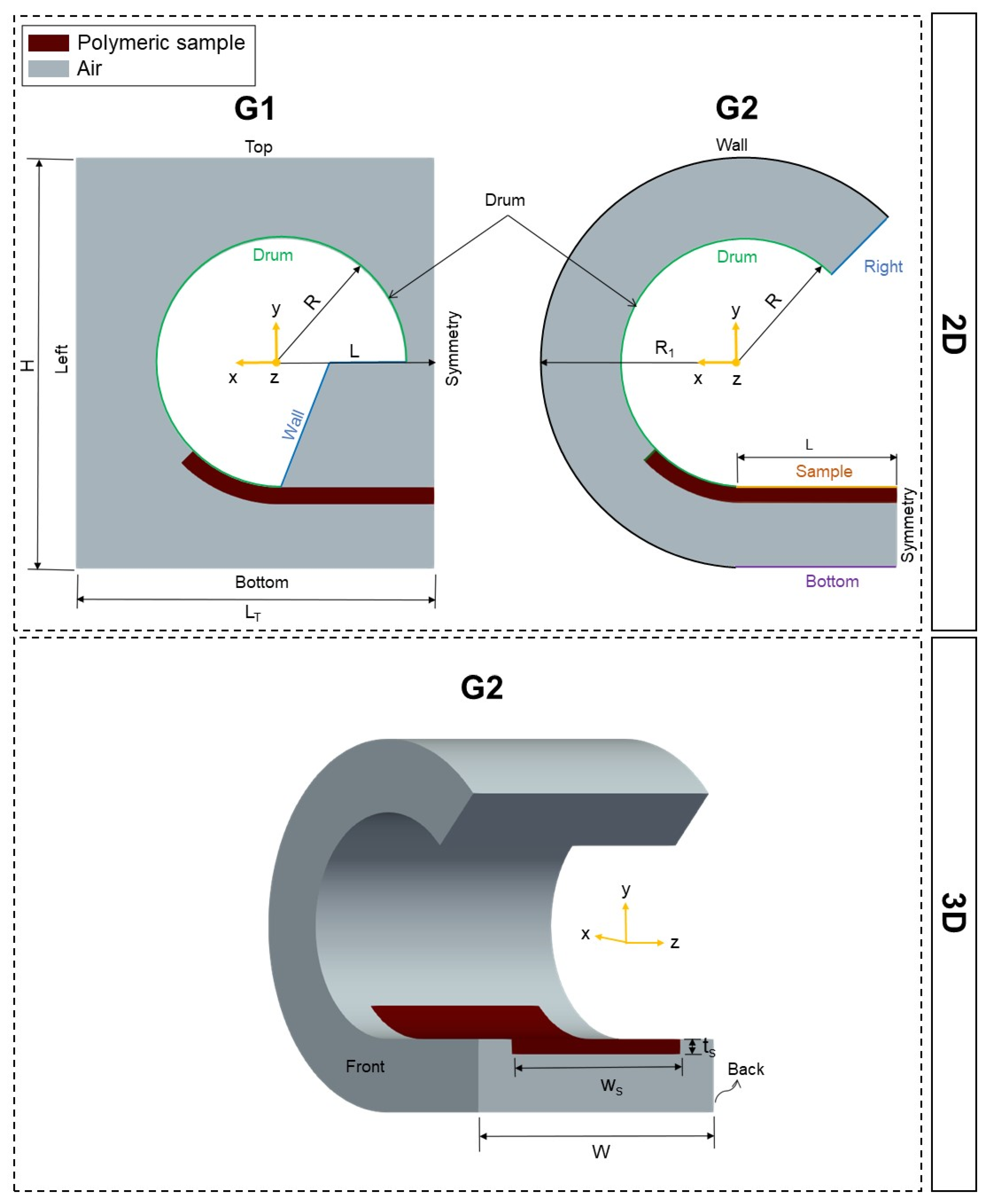
The two geometries employed in this work are illustrated in
Figure 2: G1, which was used on the initial modelling trials, and G2, which was proposed after diagnosing some limitations of G1. All the geometries, 2D and 3D, comprise two fluid regions: the polymeric sample (red region) and air (gray region). The parameters that define G1, which is 2D, are the height (
= 17 mm); total length (
= 14.86 mm); polymer sample initial length (
= 6.36 mm), which is the same as half of the distance between the two drums; and the drum radius (
= 5.155 mm). The parameters that define G2, in both 2D and 3D, are
and
, as defined for G1, and the outer radius (
= 8.5 mm), which defines the modelled domain size. The 3D version of the G2 geometry comprises some additional parameters: the width (
= 14 mm), the sample width
= 10 mm), and the sample thickness (
= 0.7 mm).
As illustrated in
Figure 2, and due to symmetry reasons, only half of the system geometry (see
Figure 1) was considered in the computational model, which allows substantially reducing the calculation time without affecting the results’ accuracy.
As shown in
Figure 2, an additional sample region that sticks at the drum surface was considered. This replicates what is carried out experimentally and aims at assuring that the drum surface speed is transmitted to the sample.
3.2. Computational Methods
The multiphase incompressible, isothermal, and immiscible flow solvers used in this work are the interFoam [
44] and the interIsoFoam [
45,
46], both available in the open-source OpenFOAM computational library [
47,
48]. The location of the interface is known only at the initial time (see
Figure 2), and along the modelling process its location must be calculated as part of the solution. The interFoam and interIsoFoam solvers follow the volume of fluid (VOF) method [
49], the most popular variant of the interface capturing approaches [
48,
49,
50], which correspond to an Eulerian approach. The main advantage of the Eulerian approach, when compared with the Lagrangian counterpart, is the use of static meshes, thus avoiding the need to deal with complex mesh manipulation algorithms. On the other hand, the main difficulty to be solved by the Eulerian-based methods is the minimisation of the interface diffusion, which is inherent to these methods, while the ones that resort to moving meshes have sharp interfaces (boundaries).
In Eulerian approaches, a function value (
) is defined to track the fraction of each cell occupied by each one of the fluids (air and polymer) [
48,
49]. In particular, in this work, a value of 1 for
corresponds to a cell full of one fluid, which in this work is the polymer, while
equal to 0 indicates that the cell is full of the other fluid, the air. Cells with
values between 0 and 1 are the ones where the interface is located. The interFoam solver uses an algebraic approach of the VOF method, while the interIsoFoam uses the isoAdvector [
45,
46] algorithm, a geometric approach of the VOF, to capture the interface. The isoAdvector algorithm computes the position of the fluids’ interface surface, while the algebraic approach does not take that into account. Thus, the former is known to provide much sharper interfaces, with the disadvantage of requiring a larger computational time.
3.3. Initial and Boundary Conditions
Initial conditions are the initial values of the computational unknowns, being required in the modelling of unsteady cases, as the ones solved in this work. The following initial conditions were assumed for the velocity, pressure, and : null values for velocity and pressure, for the field a value of 1 was imposed at the polymeric sample cells, and a zero value was set for the remaining (air region).
The boundary conditions employed for geometry G1 (see
Figure 2) were the following: for the velocity field, a rotating wall boundary condition with angular velocity of 0.987 rad·s
−1 (corresponding to a 0.8 s
−1 constant Hencky strain rate) was imposed at the drum, where the
z-axis was the rotation axis; moreover, a null normal gradient boundary condition was used at the wall, top, left, and bottom surfaces. Concerning the pressure field, a null normal gradient was imposed at all patches. For geometry G2, the boundary conditions imposed for the velocity field at the drum were equal to the ones considered for G1. Moreover, a null normal gradient boundary condition was used at the wall, right, and bottom faces in the 2D case and also at the front and back for the 3D case. Finally, a slip boundary condition was imposed at the sample face. Concerning the pressure field, a null normal gradient was used at all the patches, except the right, on which a null pressure was imposed. Regarding the
field, a null normal gradient boundary condition was used on all the faces. Symmetry plane boundary condition was imposed at patch symmetry (see
Figure 2) for the velocity and pressure fields in both G1 and G2.
3.4. Case Setup
The work described in this section aimed to determine a proper setup, as well as select an appropriate configuration, to model the uniaxial extensional rheometry tests. In order to facilitate the modelling process, the investigation started with a 2D case study, where the gravity and surface tension were neglected, and 1 s was considered for the test duration time. The discussion starts with interFoam results obtained with G1, and all the limitations are diagnosed. Then the results obtained for the 3D geometry, G2, for both interFoam and interIsoFoam solvers, are presented and compared.
3.4.1. Initial 2D Trials
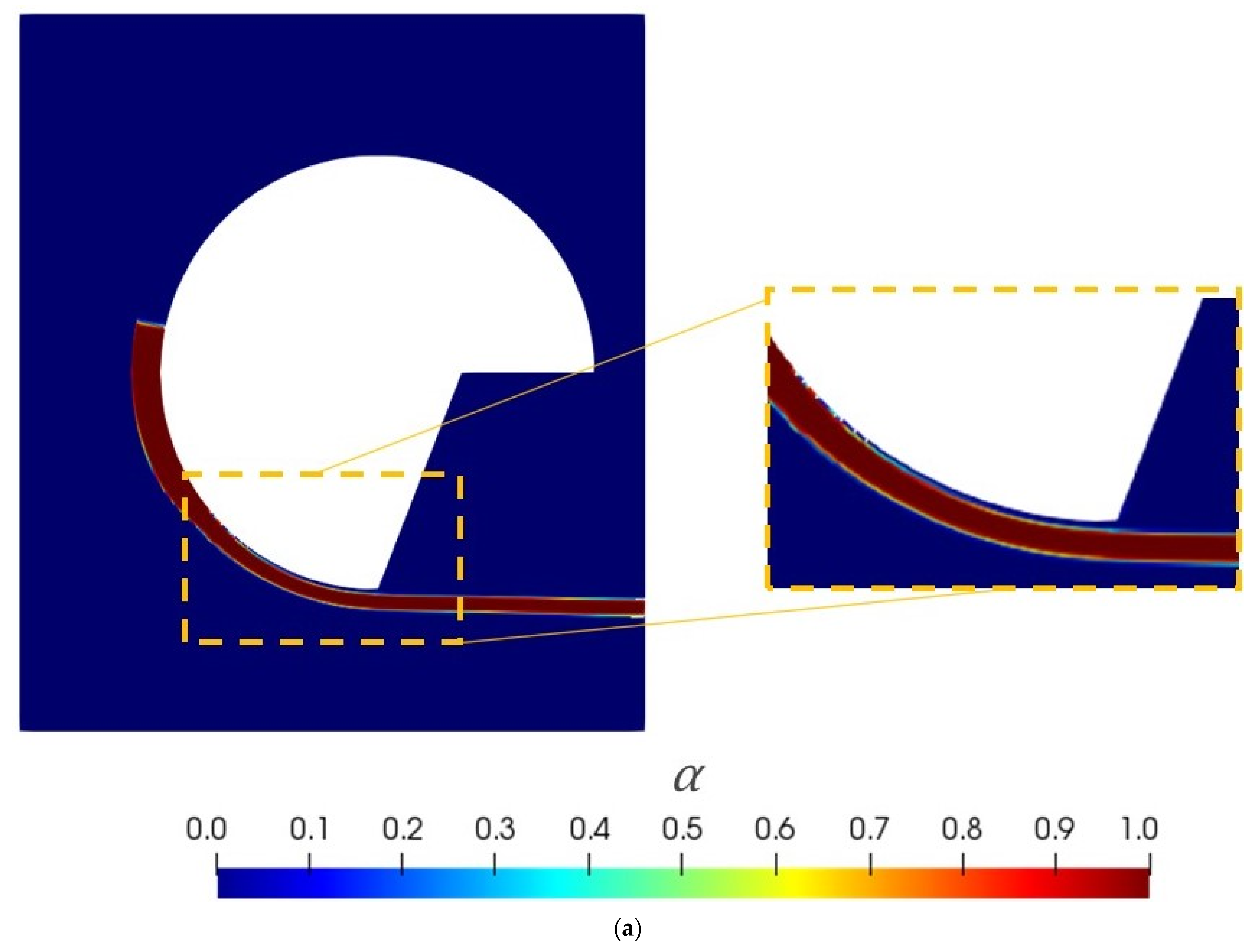
The modelling results of the interFoam solver for G1 (mesh with 79,947 cells) at a time of 1 s are depicted in
Figure 3. Ideally, the sample should always stick to the drum surface during the test, as happens in practice. However, and as depicted in
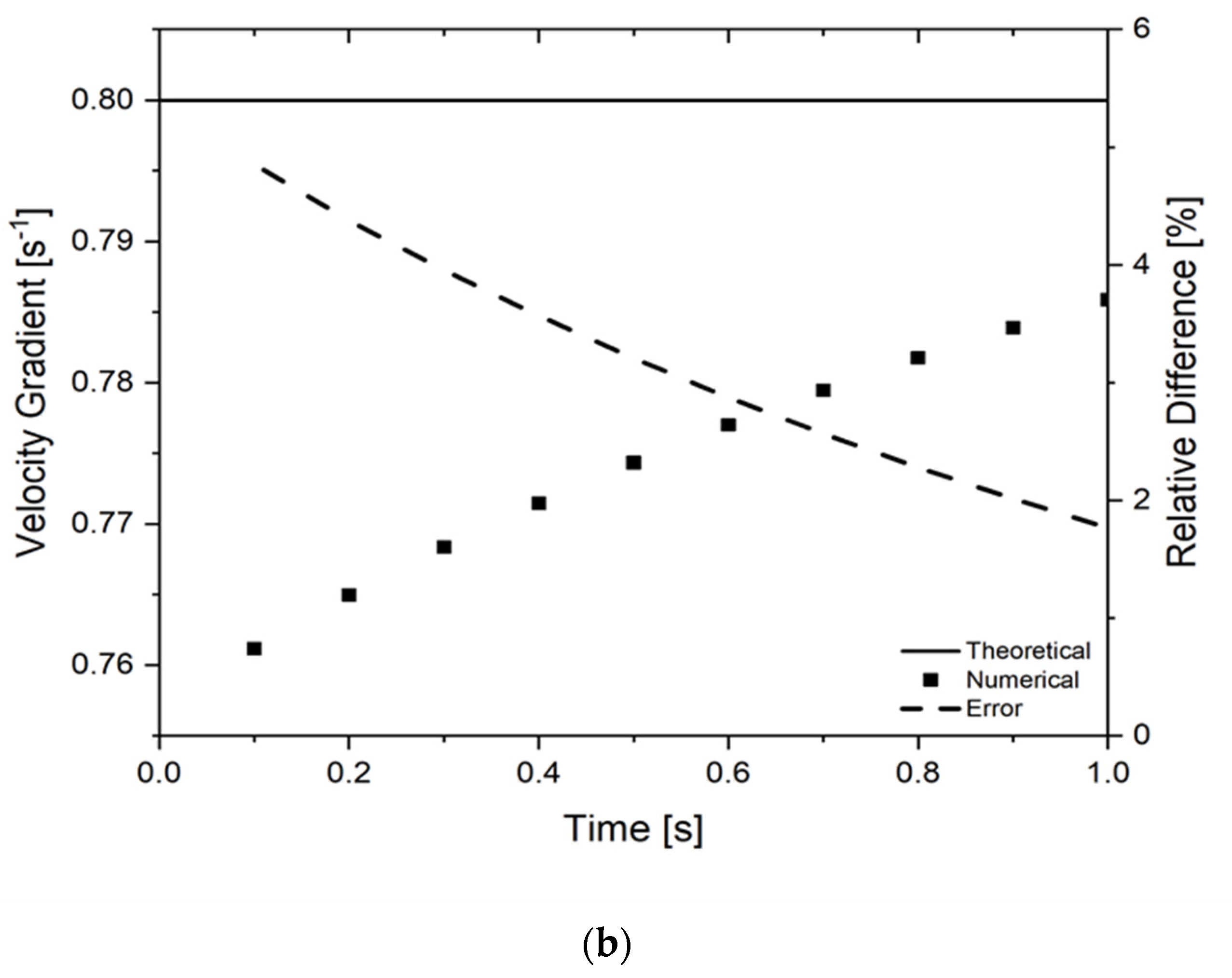
Figure 3a, an unphysical code prediction was obtained, caused by air penetration between the polymer sample and the drum. This phenomenon changed the nature of the test, promoting a significant difference between the velocity applied to the drum and that transmitted to the polymer surface, which led to a huge error (25%) in the velocity gradient calculated at the symmetry plane, as depicted in
Figure 3b.
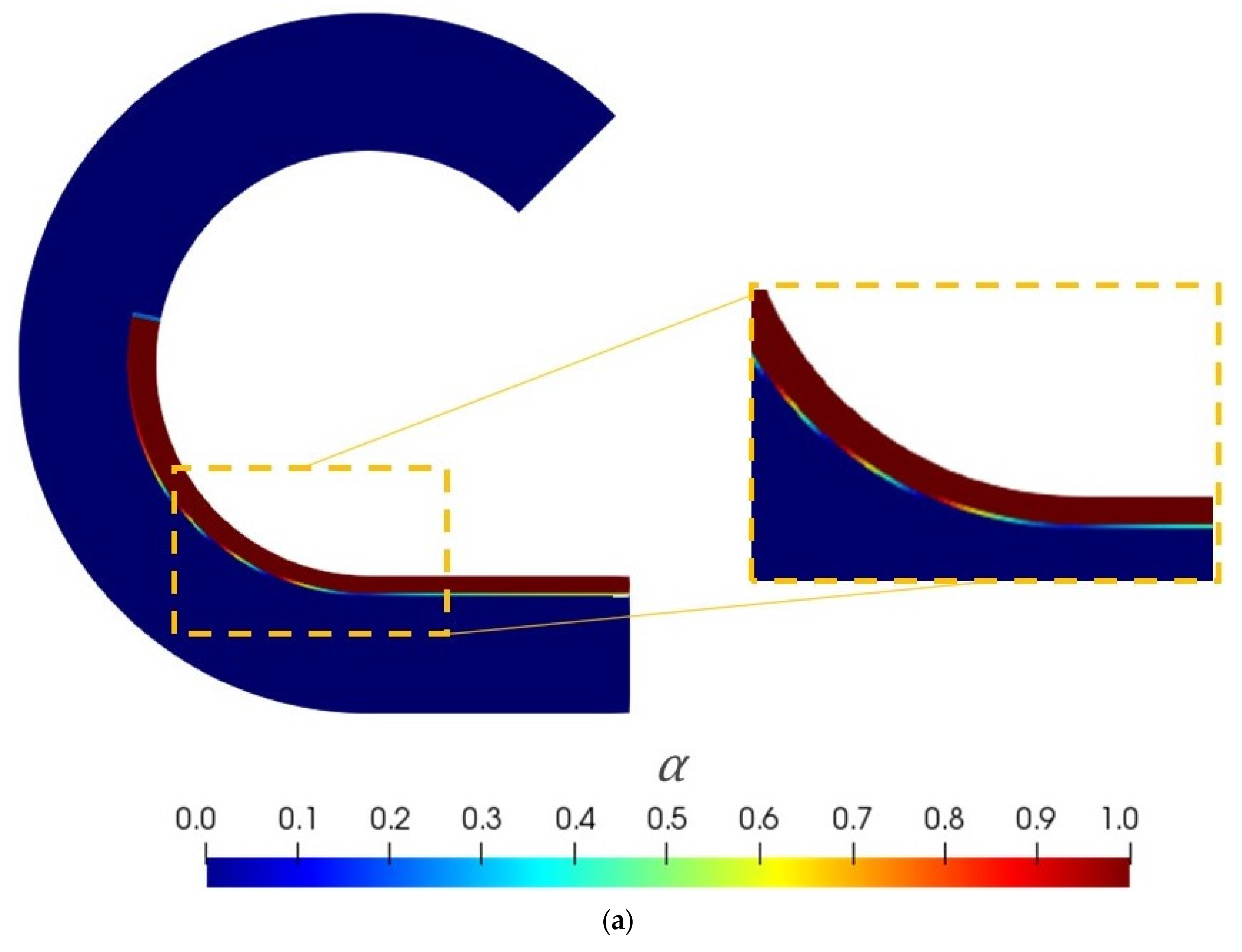
After some unsuccessful trials with G1, which always involved the above-mentioned air penetration, the new geometry, G2 (mesh with 26,790 cells), was proposed in order to eliminate the problem described. As depicted in
Figure 4a, the air penetration problem was solved with this geometry. In these conditions, the predicted velocity gradient was in very good agreement with the theoretical one, and the error reduced considerably (≤5%), as can be seen in
Figure 4b. A small difference between the numerical data and the theoretical ones, visible at the beginning of the calculation, seems to be promoted by the sample inertia, which also happens in practice.
According to the good numerical results obtained from G2 in the 2D case study, as well as the suppression of the air penetration problem, G2 and the respective boundary conditions were considered as the most appropriate computational setup for performing the required modelling studies. Therefore, for the subsequent investigations, the corresponding 3D case study (see
Figure 2), with 273,000 cells, was set up, and 2 s was considered as the test duration time.
3.4.2. Interface Capturing Method Selection
In this subsection, the numerical results obtained with the interFoam and interIsoFoam are compared in order to select the most appropriate approach for modelling the extensional rheometry test. According to the interFoam results depicted in
Figure 5, although in the 3D case study the interface between the polymeric sample and air was wavy (not sharp), the numerical modelling results were in good agreement with the nature of the extensional rheometry test. First, our assumption was that the reported problem (wavy interface) resulted from an insufficient level of mesh refinement. Consequently, a higher level of mesh refinement (mesh with 1,856,400 cells) was used, but the wavy interface problem still remained, as depicted in
Figure 5. Therefore, it was concluded that the VOF approach used in the interFoam solver was not capable of predicting the sharp interface for the present case study. Subsequently, the interIsoFoam solver was tested. As can be seen in
Figure 5, for the same level of mesh refinement (1,856,400 cells), a sharp and physical sound interface was predicted with the interIsoFoam solver. For the most refined meshes (1,856,400 cells), the time required to reach converged results with both solvers was 1 day and 23 h, and 3 days and 19 h, respectively, for interFoam and interIsoFoam, using 192 cores. The additional time required for interIsoFoam solver, inherent to its more demanding calculation procedure, was necessary to predict a realistic sharp interface.
3.5. Mesh Sensitivity Analysis
This section comprises the mesh sensitivity analysis carried out to select the most appropriate mesh refinement level to be used in the subsequent studies. According to the conclusions achieved in the previous sections, all the subsequent numerical runs were made using interIsoFoam solver with G2. In the mesh sensitivity analysis, the number of cells of the computational meshes used is as follows: M0-273,000 cells; M1-780,000 cells; and M2-1,856,400 cells. All the meshes are depicted in
Figure 6. These computational meshes were generated with the blockMesh utility [
51] available in OpenFOAM.
In order to select the appropriate level of mesh refinement, the numerical values of the cross-section area, forces, and extensional viscosities, obtained with the different meshes were compared with the corresponding theoretical values. For this purpose, the theoretical cross-section area was calculated using Equation (6). The Paraview [
52] software was used to compute the numerical cross-section area, defined by the region where
> 0.5 at the symmetry plane. The calculated theoretical normal force, using Equation (5), was compared with the numerical counterpart computed with the torque at the drum surface, using Equation (2). Then the theoretical torque was calculated using Equation (4). Finally, the cross-section area and the theoretical and numerical torques were used in Equation (7) to compute the theoretical and numerical extensional viscosities, respectively.
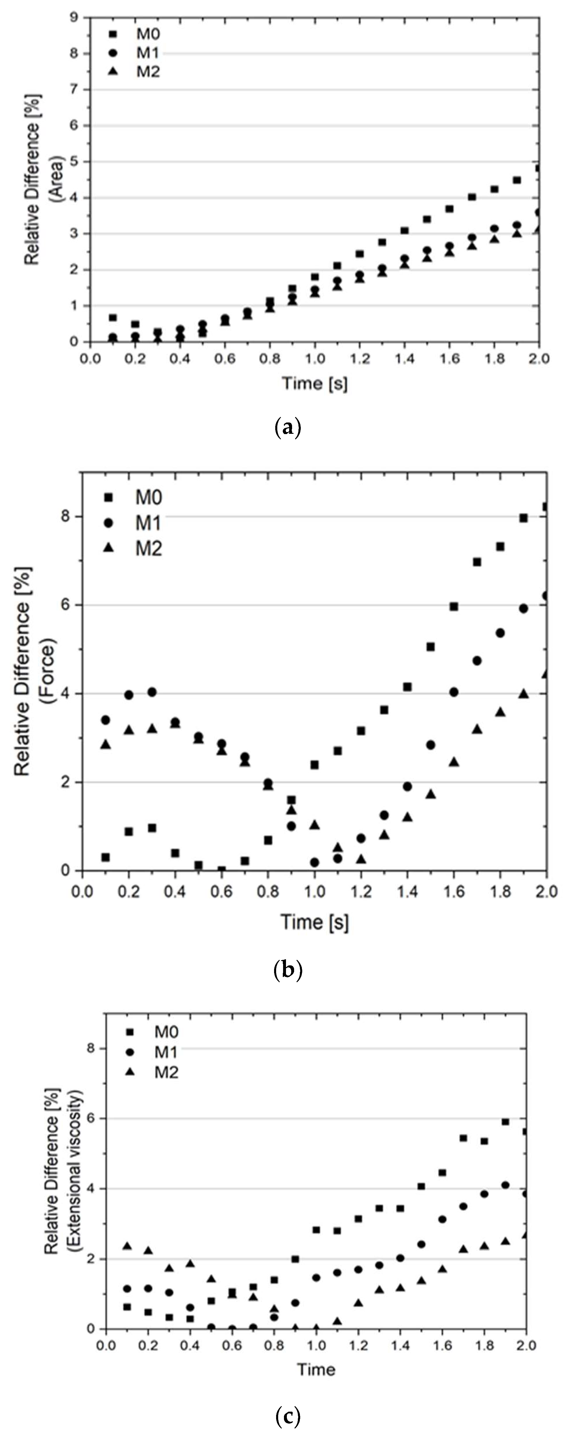
As depicted in
Figure 7, the M2 predictions for all the studied variables are considerably different from those obtained with M0, while there are smaller differences between the M2 and M1 results.
In terms of the cross-section area data, the trends are the same for all meshes, and the difference reduces with mesh refinement level. Regarding the normal force and extensional viscosity data, a small difference is only visible at the initial part of the test. This behavior motivated a more detailed analysis of the numerical calculations carried out with M2.
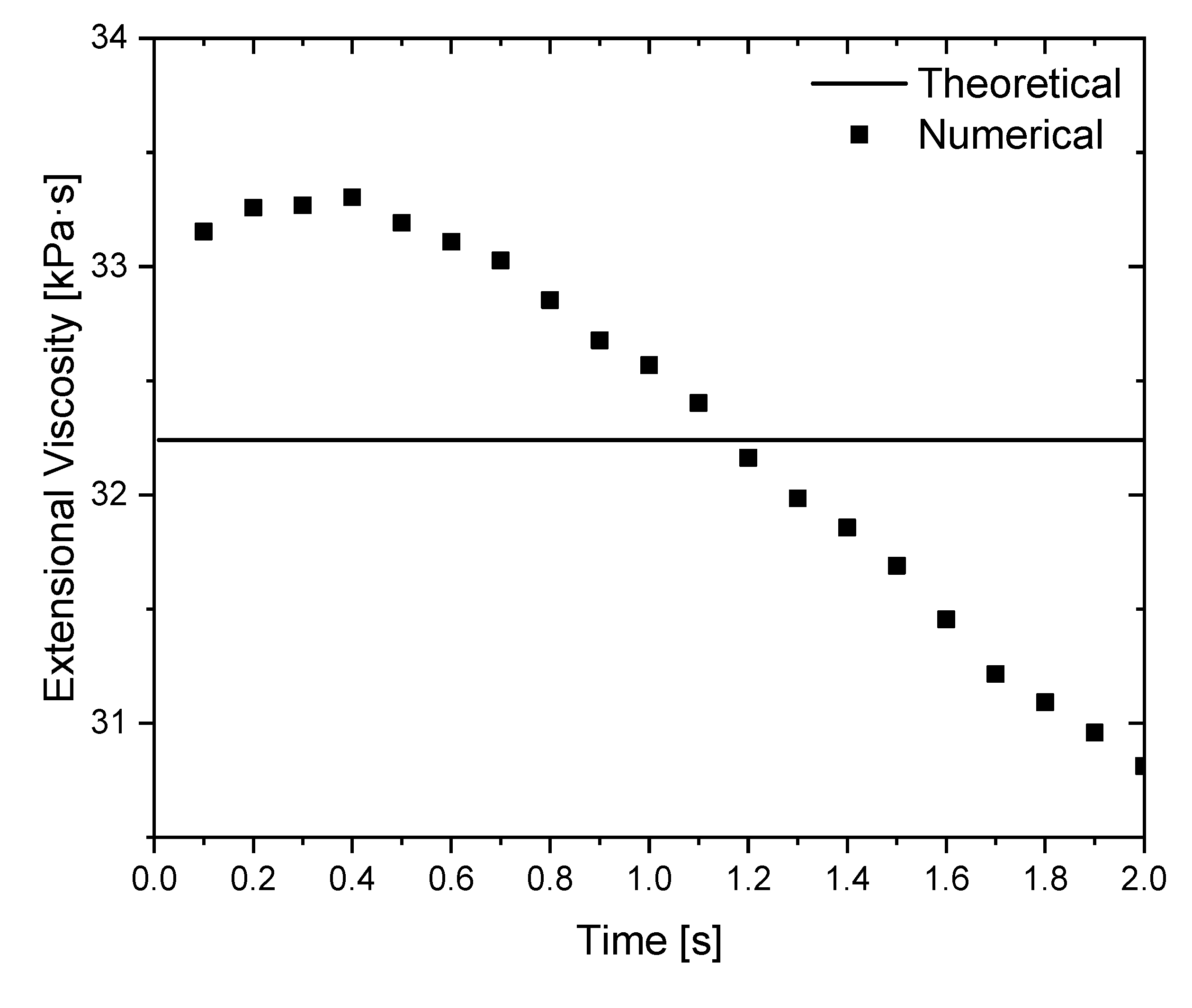
The comparison of the numerical extensional viscosity and the theoretical one using M2 is depicted in
Figure 8. As shown, the difference between the numerical and the theoretical extensional viscosities is very small. However, the numerical extensional viscosity started with a higher value, which reduces over time. This behavior seems to be related to the sample inertia, whose initial condition is at rest (see
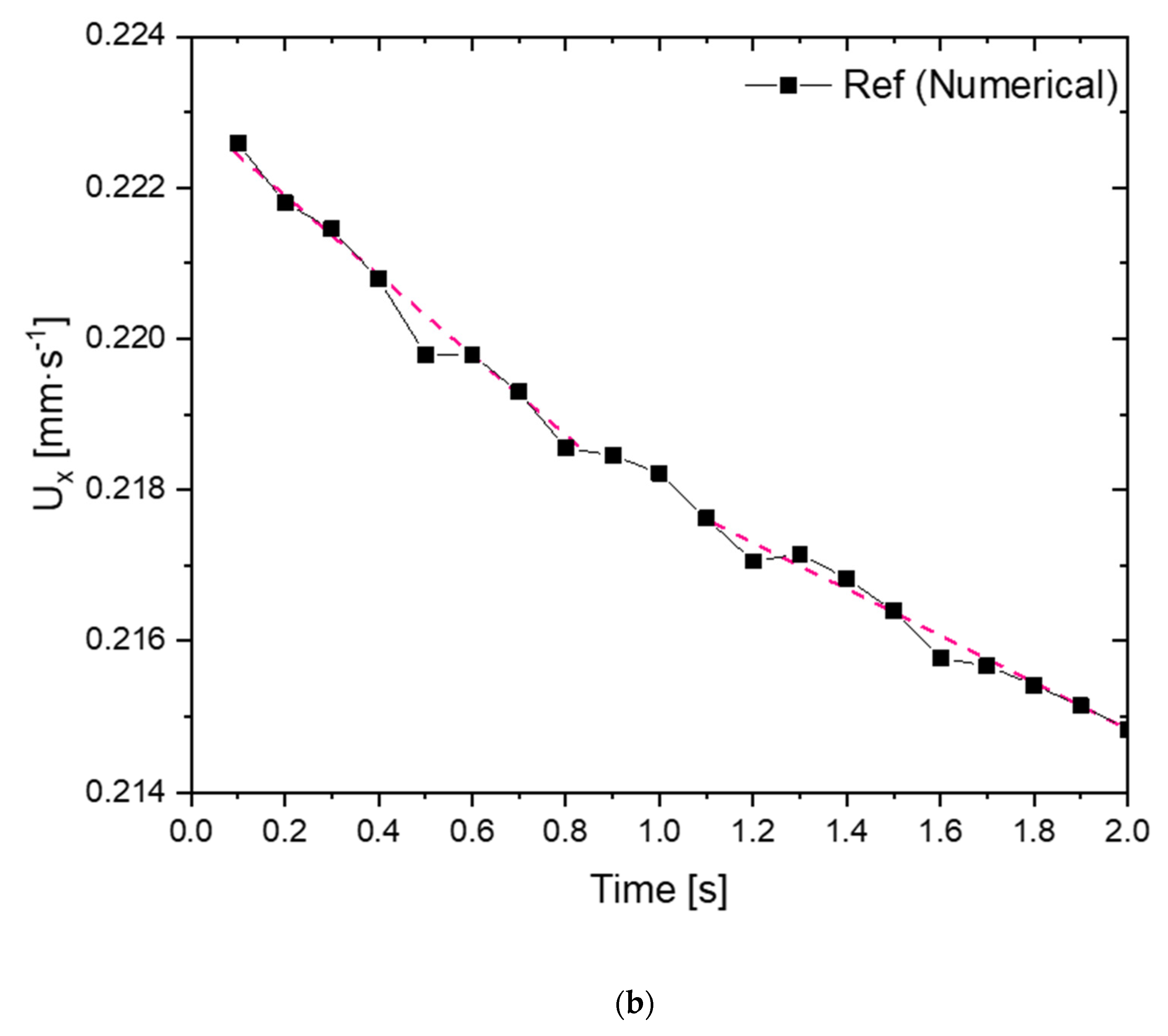
Section 3.3). To confirm this conjecture, the velocity evolution of one computational cell, whose location is depicted in
Figure 9a, was analysed.
As shown in
Figure 9b, the velocity slope (acceleration) is high at the beginning of the test but reduces along with the test, i.e., the velocity tends to a constant value. In fact, in the numerical calculation a sudden acceleration is imposed on the sample at t = 0 s. Consequently, due to inertia, the required torque is higher at the initial time steps since the polymer sample must be accelerated and deformed, which results in a higher extensional viscosity. Over time, the sample velocity tends to a steady-state distribution (null velocity slope) and, consequently, the extensional viscosity reduces and then stabilises. In fact, the time covered in the numerical case study was not enough to reach the referred steady-state conditions. These results show that inertia might affect extensional rheometry tests, which should be analysed in detail in future works.
According to the results obtained in the mesh sensitivity analysis, all the subsequent numerical runs were made using M2. For this level of mesh refinement, the calculation time was approximately 4 days, using 192 cores.
3.6. Effect of Gravity
The effect of considering or not gravity in the numerical modelling of SER tests was not studied before, despite it might influence the results, especially when low viscosity materials are considered. In order to diagnose the effect of this parameter, a case study was set up considering the gravity equal to 9.81 m·s
−2 in the negative z-direction. As depicted in
Figure 10, the extensional viscosity obtained when gravity is considered, is exactly the same as the one obtained in the numerical case where gravity is neglected. Accordingly, gravity was not considered in the subsequent studies.
5. Conclusions
The present work dealt with the numerical modelling of the uniaxial extensional rheometry tests performed with the Sentmanat extensional rheometer (SER) platform, using the OpenFOAM computational library, and aimed at establishing a modelling framework for these rheometry tests, which should provide additional insights on the relevance of the test parameters and potential error sources, to guide the work of interested experimentalists.
The initial phase of the studies aimed to define an appropriate modelling setup for the extensional rheometry tests. For that purpose, different geometries, boundary conditions, and modelling setups were tested. The selected combination of the system geometry and boundary conditions was the one that did not promote errors in the numerical results, such as the air penetration between the polymeric sample and the drum surface. Moreover, when the interface capturing approach was based on the algebraic approach of the Volume of Fluid method, some instabilities were observed on the predicted interface, which were absent when the geometric (isoAdvector) approach was employed. Consequently, the latter was selected to perform the modelling studies. The definition of the modelling setup also comprised the selection of the appropriate mesh refinement and the conclusion that the gravity can be neglected without affecting the numerical results. The numerical calculations were successfully performed with an Eulerian-based approach.
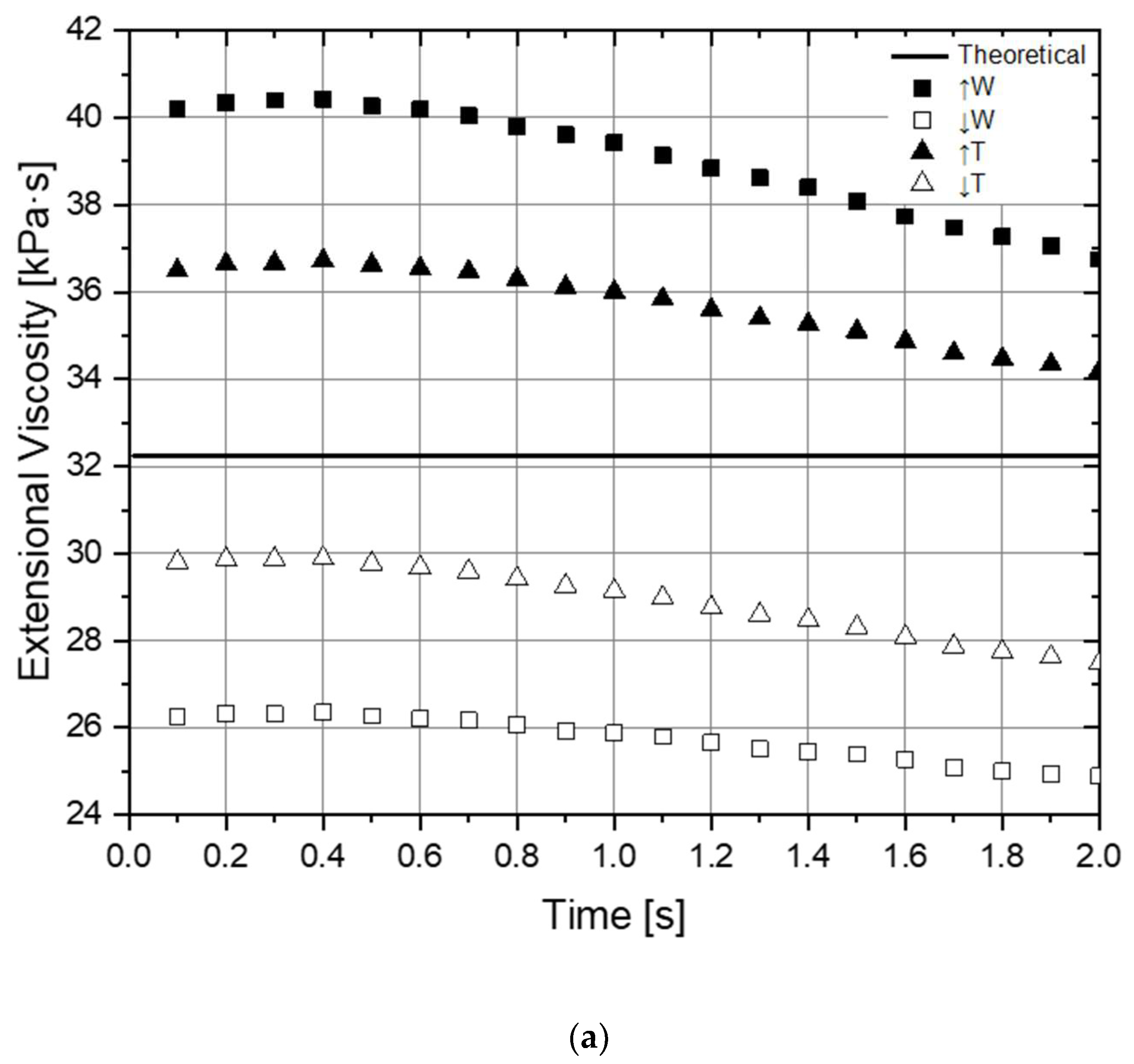
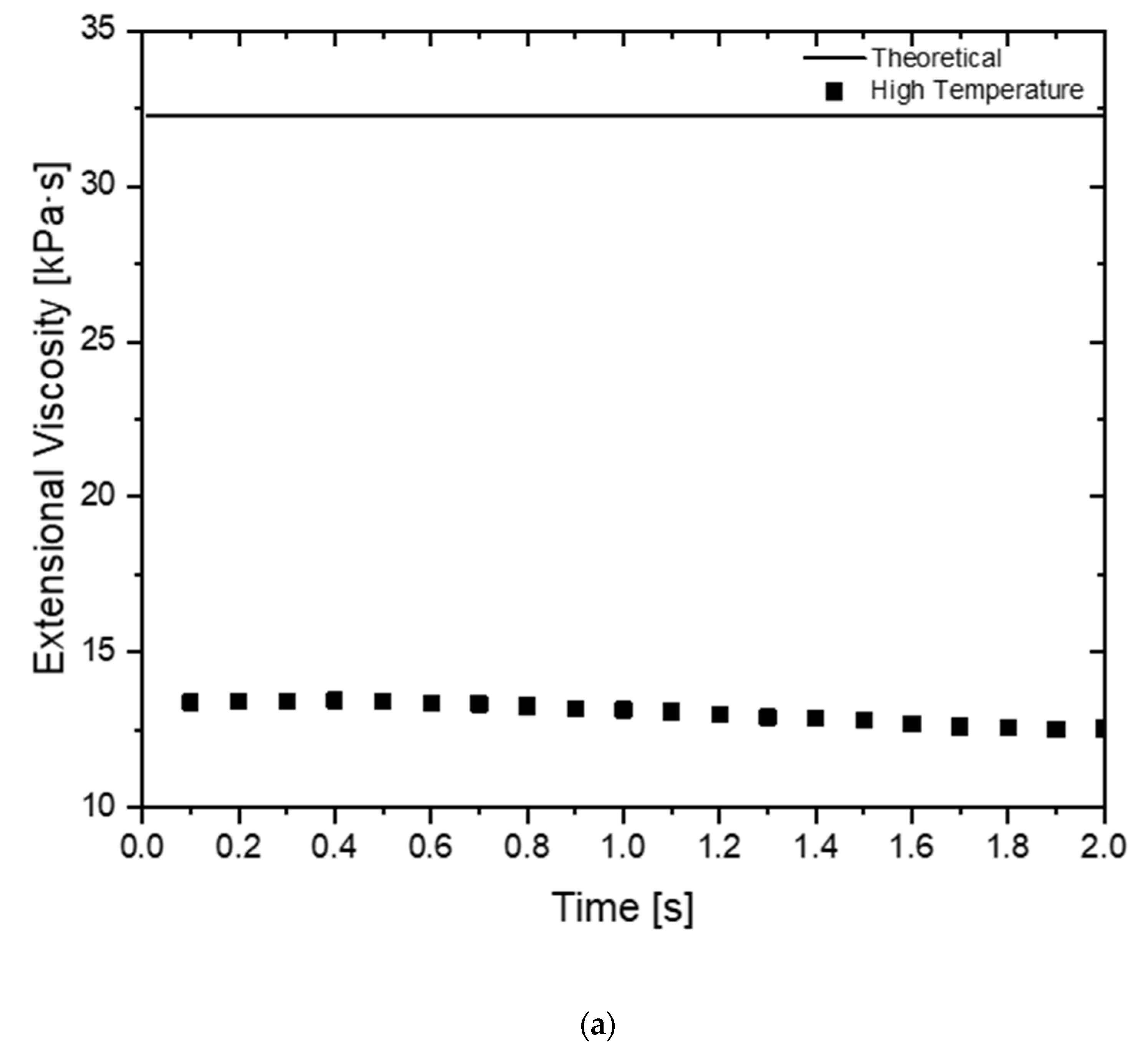
The second part of the study aimed to evaluate the effect of some common experimental errors, namely the sample dimensions, width and thickness, and the test temperature. The results obtained allowed concluding that the errors on the sample dimensions have similar effects on the predicted extensional viscosity, being approximately proportional to the induced errors, which, in the work, were ±10% and ±20%, respectively, for the thickness and width. On the other hand, a similar error order of magnitude on the test temperature (+8%) induced a huge difference in the predicted extensional viscosity (60%), which emphasises the relevance of having an accurate control on this test parameter.
The results obtained also showed that inertia, which is present in practice, plays a relevant role in the results obtained since the extensional viscosity predicted at the initial phase of the test is always higher than that at the end. This happens because at the initial phase of the test the torque applied to the drum surface is used both to deform and accelerate the polymer sample, while in the theoretical test assumptions only the sample deformation is considered. This phenomenon and the role of inertia in the extensional tests should be studied in more detail in future work. Moreover, the identified modelling setup should be employed to study more complex rheology materials, following viscoelastic constitutive models.

