1. Introduction
Nickel–titanium (NiTi) files, instead of stainless steel hand files, are being increasingly used for the preparation of root canals in endodontic treatment. Different manufacturers have produced files with improved geometries, materials, and manufacturing methods in an attempt to develop more efficient and durable files [
1]. Some of these new instruments no longer meet the ISO 3630 standard [
2], which was developed for stainless steel tools [
3]. These new instruments increase the options for professionals but hinder the understanding of the suitability of different files for particular clinical cases [
4].
Characteristics such as taper, cross-section shape, and helix and rake angles, as well as the separation between successive cutting blades, are critical for the clinical outcome of root canals and also affect the mechanical strength of the files. Other factors, such as the file material, thermal treatment, and the geometry of the root canal, also affect the life expectancy of the files, whose fracture during root canal preparation is one of the main concerns for clinicians. These effects have been analyzed through in vitro tests [
5,
6,
7,
8,
9,
10] or computer simulations [
11,
12,
13,
14]. A thorough literature review of the latter has been conducted [
15].
Computer simulations using the finite element (FE) method are particularly interesting in this context, because they allow for the analysis of the effect of specific design parameters on the mechanical strength of a file, thus avoiding unwanted random changes in other parameters. FE models can be used to adequately reproduce the experimental in vitro tests of endodontic rotary files [
11,
12,
16,
17,
18]. A recent review [
19] showed that the finite element method is a reliable tool for evaluating the behavior of NiTi rotary instruments and reduces instrument development time and costs. Moreover, these models provide information about the stresses and strains in different file regions, thus helping to understand the reasons behind their fracture during use.
However, FE models are based on geometric models of files, which are challenging to accurately obtain due to the complex three-dimensional helical shape of a file. As such, 3D CAD or complex scanning methods must be used; however, even using these advanced techniques, the geometry of the final model will be different from that of the actual file.
Roda-Casanova [
20] developed an automated procedure for simplifying the capturing of this geometry and its discretization into finite elements. However, this method is purely geometric and does not reproduce the manufacturing method followed to produce a file, which introduces geometric dissimilarities between the model and actual file. Moreover, the real geometry of a file differs from the nominal geometry [
21], which is probably due to the manufacturing method. The accuracy of the geometric model of the file is important, because small differences in geometry can substantially affect crack initiation and the fatigue life of the mechanical elements that are subject to variable loads [
22]. Therefore, a method is needed for generating the geometric model of a file based on the actual manufacturing method.
Different methods have been developed and used for manufacturing endodontic files. The file material influences file selection. Stainless steel files can be produced either by grinding the flutes, with subsequent grinding to obtain the taper, or by twisting the file blank with different initial sections, such as triangular or squared sections [
23]. With the advent of NiTi, manufacturing methods initially shifted to grinding, because the hyperelastic behavior of this material hinders the twisting of the file to a permanent shape. However, heat treatments solved this issue, thus allowing for the use of twisting as a method for manufacturing NiTi files and paving the way for the introduction of M wires [
1].
Different researchers have tried to improve the manufacturing process for endodontic files by applying machining or grinding. Several patents [
24,
25,
26] claim to provide methods for producing files with increased flexibility and resistance to torsional breakage. These methods are based on the use of a grinding wheel that rotates, thus contacting the file blank, while being translated and rotated relative to the wheel, thus machining helical flutes. Hoppe et al. [
27] patented a similar process. Some commercial machines follow this manufacturing method [
28]. Taylor et al. [
29] proposed an improved multipass method for grinding using a similar principle. Other machining methods were then proposed to increase the quality of the manufactured file using high-speed milling tools instead of grinding wheels [
30,
31]. These methods have some advantages, such as faster production speeds, the avoidance of microcracks in the file, and a lower impact on the properties of the material.
In this paper, we present a computational method that enables the automatic generation of realistic geometries of endodontic files, thus reproducing the manufacturing methods that involve the use of grinding wheels. This is a first step in more accurately capturing the geometries of endodontic files to feed FE models, with the aim of increasing the quality of the simulations of root canal preparations. In addition to constructing models to generate file geometry, we analyze the effect of the different geometric and kinematic manufacturing parameters on the final file geometry, thus highlighting the changes observed in the file cross-section. To the best of our knowledge, this is the first study in the scientific literature to simulate the generation of endodontic files produced via grinding manufacturing methods.
2. Description of the Endodontic File Manufacturing Process
The manufacturing of endodontic files via a grinding process is described in U.S. patents 5.527.205 [
24] and 5.807.106 [
25]. Subsequently, several companies (such as
Royal Master and
Rollomatic) developed grinding machines to produce endodontic files with different dimensions and shapes. This manufacturing method is briefly summarized in three steps to provide the required background to understand the computational methods that are described in this paper:
Step 1. The raw material for the endodontic file is shaped into a cylinder with length
and diameter
(
Figure 1a).
Step 2. The raw material is shaped to create a blank for manufacturing the endodontic file:
Initially, the tip of the blank undergoes frustoconical grinding and is characterized by dimensions
,
, and
(
Figure 1b).
Then, the tip of the blank is rounded with a radius
(
Figure 1c). Radius
must be calculated from tangency conditions considering
,
, and
to maintain the dimensions of the blank and achieve a fully rounded tip.
Finally, the blank is subject to frustoconical grinding to shape the active part of the endodontic file (
Figure 1d). The conicity of this part is characterized by dimensions
,
, and
, where
is calculated from
,
,
, and
. The length of the shaft is defined as
.
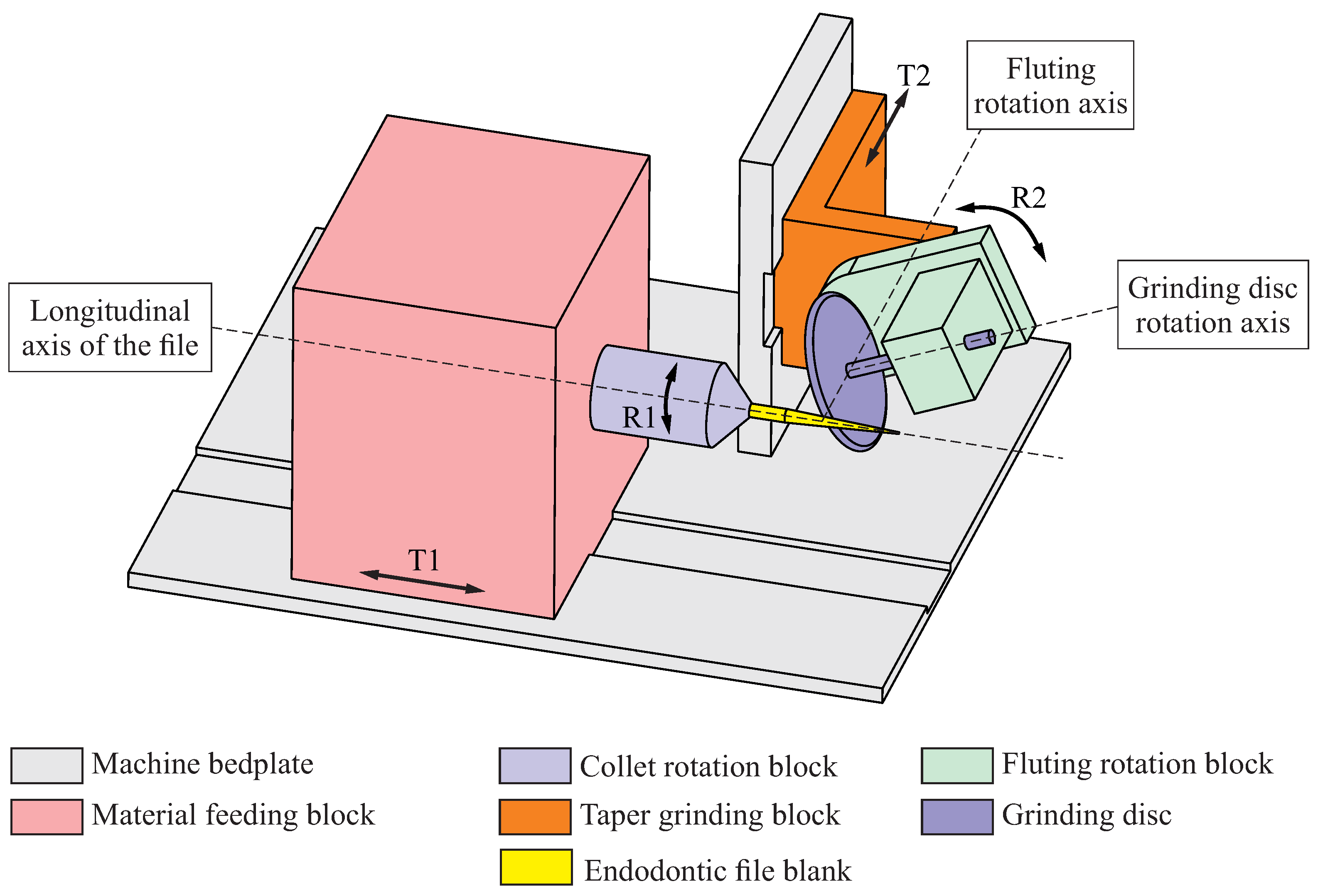
Step 3. A blank with the dimensions and shape of the final root canal instrument is obtained. Then, the helical flutes are machined onto this blank using a deep-grinding apparatus, which is akin to the one depicted in
Figure 2. The basic setup for this machine is as follows:
The proper combination of the described movements (rotations R1 and R2, translations T1 and T2, and the rotation of the grinding wheel) allows the flute of the endodontic file to be machined. Repeating this combination of movements with an indexed initial position allows for the machining of several flutes using the endodontic file blank.
3. Mathematical Representation of the Geometry of an Endodontic File
In this section, we provide the mathematical expressions that define the geometry of the blank, the geometry of the flutes that are generated from the blank via the grinding process, and the geometry of the resulting endodontic file. Moreover, the mathematical expressions that define the lead and distance as a function of the generalized parameter of the flute grinding process are provided.
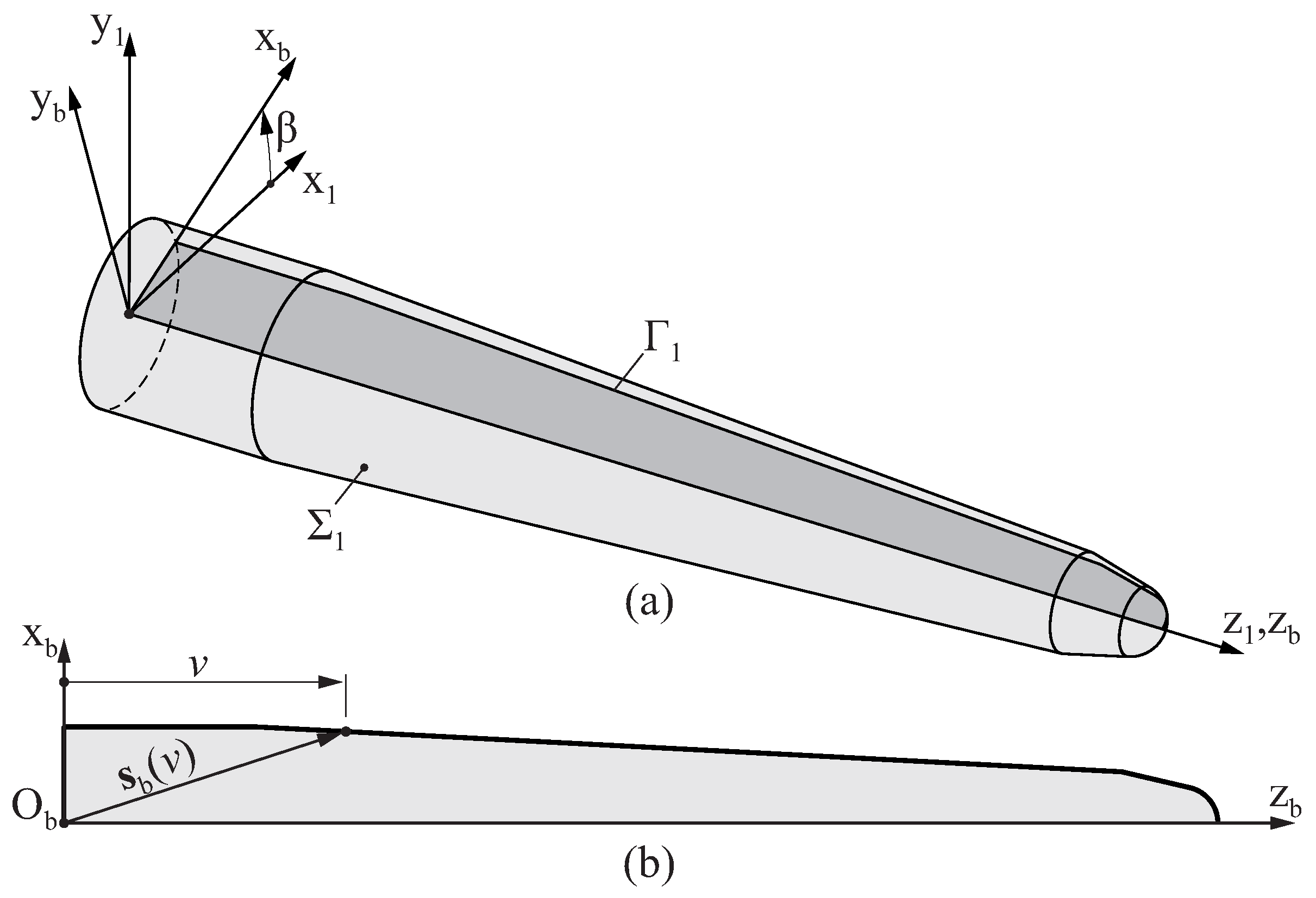
3.1. Mathematical Representation of the Blank of an Endodontic File
After the second step of the manufacturing process of the endodontic file described in
Section 2, a blank is produced with the final dimensions of the endodontic file (see
Figure 1d). The surface
that defines the geometry of this blank is obtained by revolving a plane profile
around axis
, as depicted in
Figure 3a.
Figure 3b shows a generic profile of an endodontic file blank. The geometry of this profile is defined with respect to coordinate system
using a parametric function
that provides the coordinates
of a point in the profile of the blank from its longitudinal intrinsic coordinate
v.
Surface
is represented in coordinate system
as:
where
is the polar intrinsic coordinate of the blank surface, and
is a homogeneous transformation matrix from coordinate system
to coordinate system
that is defined as
3.2. Mathematical Representation of the Flutes of an Endodontic File
The surface
that defines the geometry of the grinding wheel is determined by revolving a plane profile
around axis
, as depicted in
Figure 4a.
Figure 4b shows a generic profile of a grinding wheel, which is defined with respect to coordinate system
using a parametric function
that provides the coordinates
of a point in the profile of the grinding wheel from its profile intrinsic coordinate
u. The Cartesian components of the unit vector that is normal to the wheel profile are given by parametric function
.
Surface
is represented in coordinate system
as
where
is the polar intrinsic coordinate of the grinding wheel surface, and
is a homogeneous transformation matrix from coordinate system
to coordinate system
, which is defined as follows:
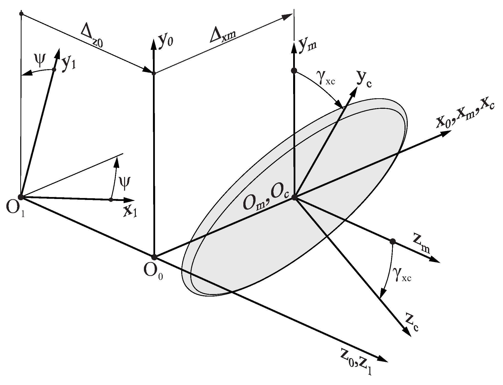
Figure 5 shows the coordinate systems that are used to represent the grinding wheel surface
with respect to the different components of the grinding machine:
Coordinate system is rigidly connected to the grinding machine bedplate, and its axis is aligned with the longitudinal axis of the endodontic file.
Coordinate system is rigidly connected to the taper grinding block, which is parallel to coordinate system , and its origin is located over the axis at a distance from . The distance may vary during the grinding process to account for the taper of the endodontic file; thus, depends on the generalized parameter of the flute grinding process .
Coordinate system is rigidly connected to the grinding wheel. When assembled into the grinding machine setup, both the origin and the axis of are coincident with the origin and the axis of . However, coordinate system is rotated by an angle around the axis in order to take into account the tilting of the grinding wheel with respect to the axis of the endodontic file. Angle is assumed to be constant throughout the entire flute generating process.
Coordinate system is rigidly connected to the endodontic file, and its origin is located over the axis at a distance from . Moreover, the and axes of these coordinate systems are coincident, but is rotated by an angle with respect to .
Coordinate transformation from
to
allows for the grinding wheel surface
to be represented in its working position with respect to the endodontic file:
where
,
, and
are homogeneous transformation matrices defined as
Here, the
function relates the rotation of the blank to the translation of the material feeding block (movements T1 and R1 in
Figure 2) through the lead
of the file, which is defined as
The geometry of the flute of an endodontic file is obtained as the envelope to the family of surfaces given by
, which is calculated by solving the following equation:
Here,
and
are defined as follows:
where
3.3. Mathematical Representation of the Geometry of an Endodontic File
Section 3.1 and
Section 3.2 contain the mathematical expressions that define the geometry of the surface of the blank and the flutes of the endodontic file, respectively. The circular cross-section of the blank at any longitudinal position, defined by coordinate
, can be determined using Equation (
1) and setting
while varying
.
Figure 6a shows an example of a cross-section of the blank.
The geometry of the flutes of an endodontic file can be determined by simultaneously considering Equations (
5) and (
10). The cross-section of the flutes at any longitudinal position defined by coordinate
can be found by finding the values of
and
that satisfy both Equation (
10) and the following for each particular value of
u:
where
is the unit vector in the
-axis direction.
Figure 6b shows an example of a cross-section of the flutes of an endodontic file with three flutes.
Overlapping both cross-sections, as illustrated in
Figure 6c, allows us to define the geometry of the cross-section of the endodontic file at coordinate
. The geometry of the entire endodontic file can be determined by repeating these steps for different values of
.
3.4. Establishment of a Relation between and
The application of Equation (
9) to determine the magnitude of
as a function of
requires of the definition of a function
that establishes a relation between the rotation and the translation of the blank during the flute generating process.
Even though
can take any shape, we assumed a linear relationship between the generation parameter
and the lead
in this study, which can be mathematically expressed as
where
and
are constants to be determined from the design parameters of the endodontic file, and
corresponds to the value of
that satisfies
.
Considering Equation (
9), the following explicit relationship between
and
can be obtained:
The following set of boundary conditions is considered to determine
,
, and
:
where
is the lead at the beginning of the active part,
is the lead at the tip of the file, and
corresponds to the value of
that satisfies
. The following solutions for
,
, and
are obtained with these boundary conditions:
The derivative of
with respect to
, which may be used in further calculations, is
3.5. Establishment of a Relationship between and
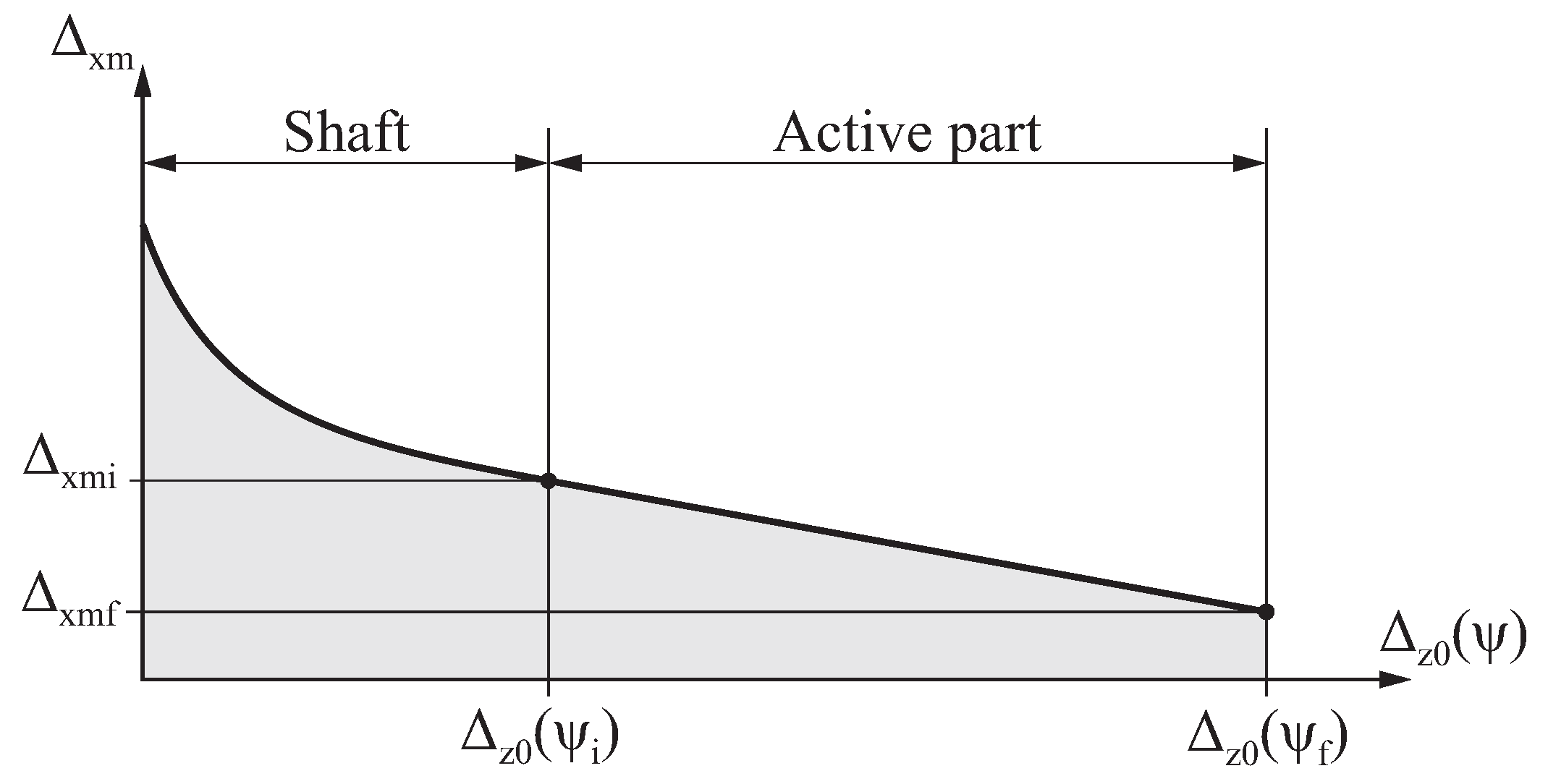
During the flute grinding process, the taper grinding block of the grinding machine moves toward the longitudinal axis of the file to account for the taper of the endodontic file. This movement is described by function , which provides the distance from the center of the grinding wheel to the longitudinal axis of the file as a function of . Function can take any arbitrary shape to obtain the geometry desired for the endodontic file.
Figure 7 shows the function
selected in this study, which is mathematically defined as follows:
where
is a user-defined parameter;
,
,
, and
are constants to be determined from the design parameters of the endodontic file. This function is linear in the active part of the file
and parabolic in the shaft
, with the aim of quickly separating the grinding wheel from the file to avoid the excessive grinding of the shank.
The derivative of
with respect to
is calculated as
Assuming that
and
, as well as by establishing
continuity conditions at
, the following solutions for
,
,
, and
are found:
4. Numerical Examples and Discussion
The performance of the proposed method in generating the geometry of endodontic files reproducing the actual flute grinding process is described in this section. Several case studies were considered for this purpose, with all of them having the same geometry for the initial blank of the endodontic file, which was defined by the parameters shown in
Table 1 (corresponding to the blank shape and dimensions given in
Figure 1).
Considering this initial blank, six representative endodontic file geometries were produced with different parameters for the flute grinding process, which are shown in
Table 2.
These parameters were classified into four categories:
The geometry of the grinding wheel: The profile of the grinding wheel with rounded edges selected for the generation of the endodontic files is shown in
Figure 8. This profile was parameterized by the radius of the grinding wheel
and the tip radius
, which remained constant for all the case studies. Any other geometry could have been selected for the profile of the grinding wheel.
The parameters that describe the movement of the material feeding block: A linear relationship between the generating parameter
and the lead
was selected, which was parameterized by
and
(see
Section 3.4). Case studies A to E included examples where the lead was constant throughout the entire length of the file, thus setting
. Case study F was an example of an endodontic file with a variable lead, where
.
The parameters that describe the movement of the taper grinding block: As described in
Section 3.5, in this study, a linear relationship between the generating parameter
and distance
was selected for the active part, whereas a parabolic function was selected for the rest of the file. These functions were parameterized by
,
, and
. The values specified for these parameters were adjusted for each particular case.
Other parameters of the grinding process included such factors as the tilt angle of the grinding wheel
and the number of flutes
n. All the case studies had three flutes, but any other integer value could be specified for this parameter. Different values were selected for the tilt angle of the grinding wheel
, which were obtained from
variations over the magnitude of the reference helix angle
of the endodontic file (see
Appendix A for further details).
Thus, following the method proposed in this study, the geometry of the flutes of the endodontic file was defined by a set of nine parameters: , , , , , , , , and n (the reference helix angle is a derived parameter). Considering the six independent parameters that defined the geometry of the blank, the geometry of the endodontic file was fully defined by a set of 15 parameters.
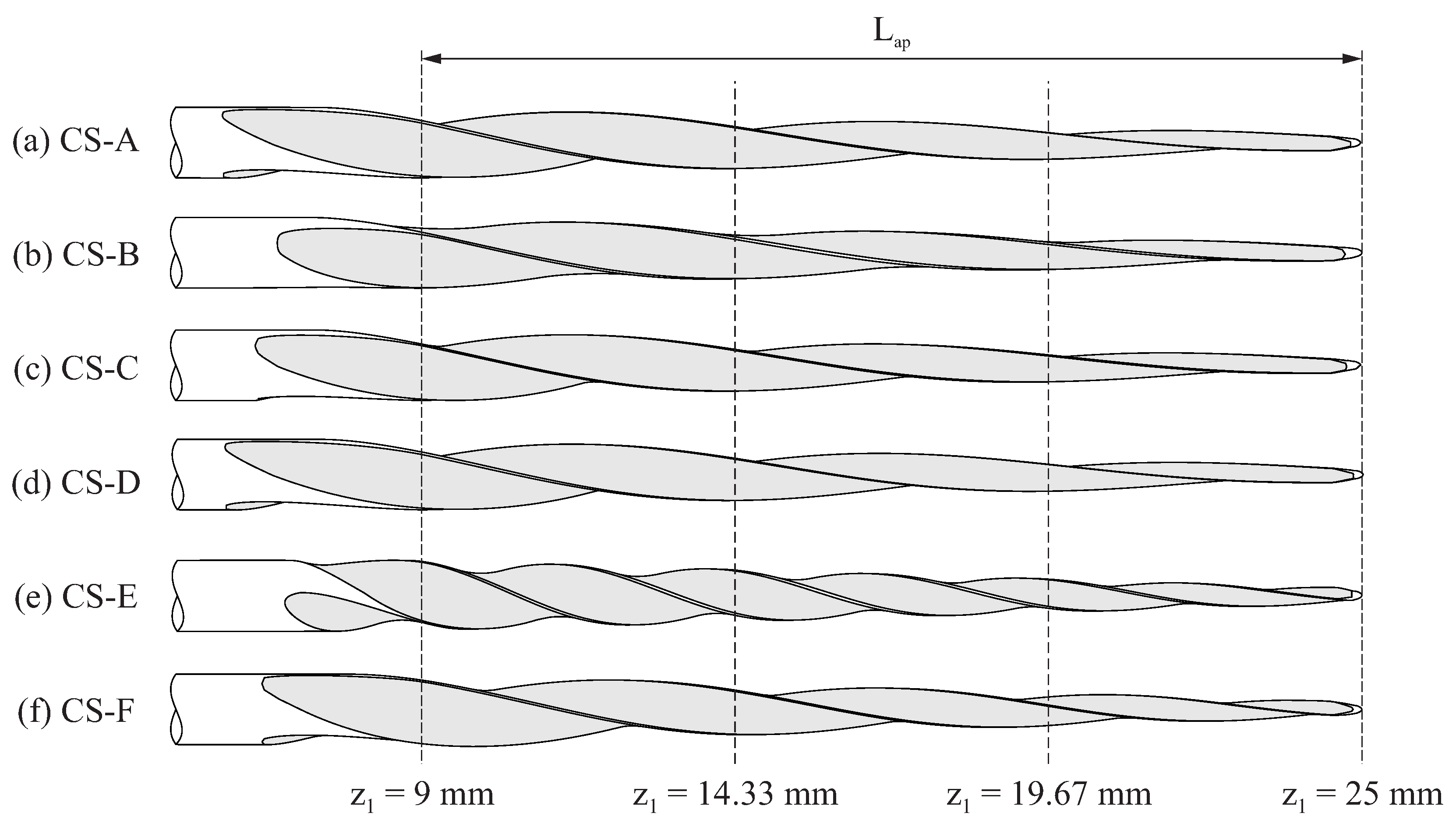
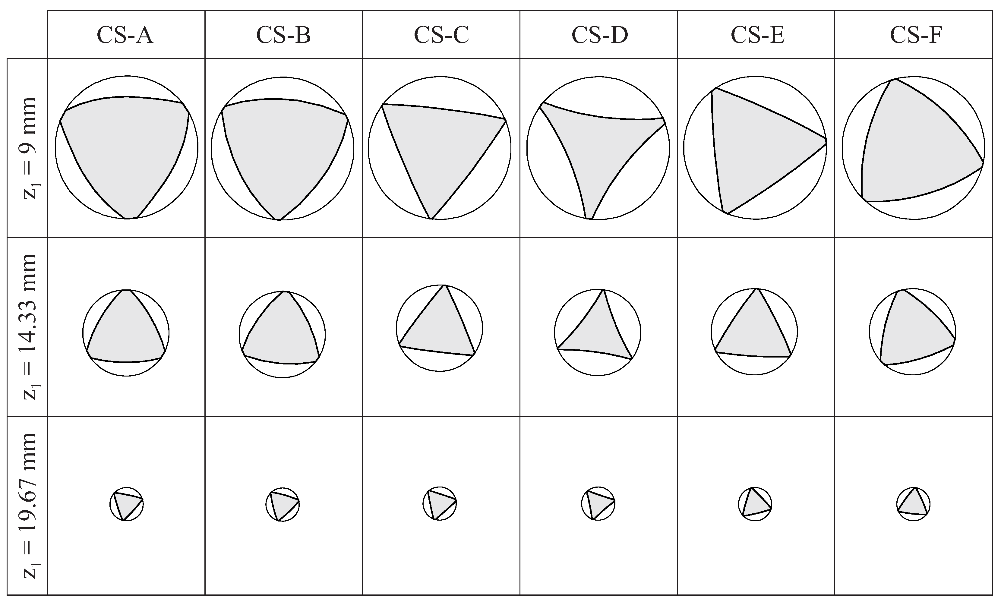
Figure 9 shows the lateral view for the selected case studies, and
Figure 10 shows the cross-sections of these endodontic files at three different positions along the active part (which are defined in
Figure 9). These figures evidence the effects of the grinding parameters on the geometry of the endodontic files.
Figure 10 shows that the shape of the cross-section changed along the length of the active part of the file. The differences between the cross-sections of the different files were more evident near the shank and became almost negligible near the file tip. These results indicate that an approximate file geometry, generated by simply rotating and scaling a section shape, as conducted in previous studies [
15,
20,
32], is not realistic for this grinding manufacturing method.
Figure 10 shows that the flute grinding parameters affected the concavity/convexity of the file cross-section. A convex cross-section tends to be stronger and less elastic [
33]; for this reason, narrow canals should be threaded during the initial phase of shaping. On the contrary, a concave cross-section tends to be more elastic but not as strong, so it may be more suitable for wider canals in the final phase of shaping. Thus, finding the specific combination of flute grinding parameters to obtain optimum curvatures for the cross-section of the files may result in better clinical outcomes.
We next investigated the effect of the tilt angle of the grinding wheel , the lead , the distance , and the tip radius of the grinding wheel on the geometry of the endodontic file.
4.1. Effect of the Tilt Angle of the Grinding Wheel
Case studies A, B, C, and D were used to demonstrate the effect of changing the tilt angle of the grinding wheel () while keeping the lead constant and uniform along the file length. A change in modifies the relative position of the grinding wheel with respect to the longitudinal axis of the endodontic file, thus affecting how the material is removed from the blank during the flute grinding process.
Figure 11a–d show the cross-section at the middle of the active part for different variations of case study B, where
was changed, while the rest of the design parameters remained constant, to demonstrate the independent effects of
over the geometry of the file. The dashed line draws an equilateral triangle circumscribed within the section of the file. This triangle has been properly aligned with the cross-section of the file to facilitate the visualization of the differences in the cross-section among the cases. Moreover, the figure includes a dashed line
that is perpendicular to the edge of this triangle. Point
P indicates the center of the cross-section, and point
Q indicates the intersection of this line with the edge of the cross-section.
In all the cases shown in
Figure 11a–d, each edge of the cross-section of the file corresponds to a segment of a circumference, with a radius denoted by
R, as indicated in
Figure 11a–d, together with distance
. Regardless of the value of
, point
Q always corresponds to the point on the edge of the cross-section that was either at a maximum or minimum distance of
P (for convex and concave cross-sections, respectively). The results show that the effect of
over distance
was negligible in this case study.
Figure 11e shows the variation in the radius of the curvature of the edges of the cross-section at the middle of the active part of case study B when only
was changed (note that cases with
and
were equivalent). Here, depending on the value of
, a convex or concave cross-section was obtained. The change from a convex to a concave cross-section (and vice versa) is characterized by a singularity point, where
R tends to infinity, thus leading to a cross-section with flat edges. In this particular case, these singularity points were observed when
and
. In the interval
, the cross-section was concave (
Figure 11d), whereas in the rest of the domain, the cross-section was convex (
Figure 11a–c).
4.2. Effect of the Lead
The lead defines the relationship between the translation and the rotation of the file during the flute grinding process; in this study, the lead was characterized by parameters
and
(
Section 3.4). A constant lead throughout the length of the file was achieved by setting
, and two examples of endodontic files with a constant lead are shown in
Figure 9c (case study C) and
Figure 9e (case study E). The proposed approach also allowed us to generate flute geometries where the lead linearly varied from the beginning to the end of the active part, as shown in
Figure 9f for case study F.
The lead of the manufacturing process affects the pitch of the file, which has clinical implications. Increasing the lead (which increases the pitch of the files) reduces the tendency to screw in and the torsional load sharing [
34]. Decreasing the pitch (which reduces the pitch of the files) increases the cutting efficiency, the bending stiffness, and the fatigue life of a file [
32,
35]. Finally, the use of variable lead files helps to reduce the amount of cutting debris retained in the flutes [
36].
Figure 12 shows different variants of case study B, where
was changed, while the rest of the design parameters remained constant, to demonstrate the independent effects of the lead on the geometry of file’s cross-section.
In all the cases shown in
Figure 12, each edge of the cross-section of the file corresponds to a segment of a circumference with a radius denoted by
R, as indicated in
Figure 12, together with distance
. Regardless of the value of
, point
Q always corresponds to the point on the edge of the cross-section that is at a maximum distance from
P, and the distance
was not affected by variations in the lead. Decreasing and increasing the lead of the file tended to decrease and increase the curvature radius of the edges of the cross-section, respectively.
According to Equation (
A3), by keeping the rest of the parameters constant, the reference helix angle of the file decreased as the magnitude of the lead increased. In the cases shown in
Figure 12, the reference helix angle
changed from −7.3 ° (when
) to −4.4 ° (when
).
4.3. Effect of the Approximation at the Beginning of the Active Part
As the flute is being generated, the taper grinding block approaches the longitudinal axis of the file, thus following a function
that was characterized by
,
and
in this study (
Section 3.5).
Figure 13 shows different variants of case study B, where
was changed, while the rest of parameters remained constant, to demonstrate the independent effects of these parameters on the geometry of the endodontic file.
In all the cases shown in
Figure 13, each edge of the cross-section of the file corresponds to a segment of a circumference with a radius denoted by
R, as indicated in
Figure 13, together with distance
. Regardless of the value of
, point
Q always corresponds to the point on the edge of the cross-section that is at the maximum distance from
P.
The results obtained from this analysis revealed that increasing tended to increase the curvature radius of the edges of the cross-section, even though this increase was almost negligible. The distance increased as increased, thus also increasing the area of the cross-section.
When
was changed while
was kept constant, the slope of the approximation function changed. As such, in the examples shown in
Figure 13, the slope changed from
(when
) to
(when
). These slopes can be compared with the slope of the file blank, which was
in all the case studies.
According to Equation (
A3), the helix angle of the file increases with the magnitude of the approximation function. In the cases shown in
Figure 13, the reference helix angle
changed from −5.1 ° (when
) to −6.0 ° (when
).
4.4. Effect of the Tip Radius of the Grinding Wheel
Finally, the effect of the tip radius
on the geometry of the endodontic file was investigated.
Figure 14 illustrates the effect of differences in the tip radius of the grinding wheel (
in
Figure 8) on the geometry of the endodontic files for case studies A to D, when the rest of the design parameters remained constant. For clarity, only one-third of the resulting cross-section in the middle of the active part is shown in this figure.
Figure 14 shows that varying
changed the curvature of the edges of the cross-section of the file, thus increasing their radius of curvature as
increased. The distance
did not change with
; thus, the area of the cross-section increased as
increased.
5. Conclusions
We developed a method for generating the geometry of endodontic files by reproducing the flute grinding process. This approach provides realistic file geometries, including files with a variable lead, using fifteen independent parameters that define the file manufacturing process.
The performance of the method was demonstrated through several case studies, which led to the following conclusions:
The tilt angle of the grinding wheel affects the curvature of the edges of the cross-section of the file. An appropriate selection of can lead to convex and concave cross-section geometries, as well as cross-sections with straight edges. The effects of on the distance are negligible.
The lead of the file, characterized by and , affects the helix angle of an endodontic file and the curvature of its cross-section. Decreasing the lead of the file decreases the curvature radius of the edges of its cross-section. The distance is not affected by changes in the lead.
The distance between the grinding wheel and the axis of rotation of the file is characterized by , , and . Changing does not affect the curvature of the edges of the cross-section but strongly influences distance .
The tip radius of the grinding wheel has a different effect on the geometry of the endodontic file depending on the settings of the grinding machine. In general, the radius of curvature of the edges of the cross-section increases with .
The computational method developed in this study is a valuable tool for designing and manufacturing root canal files with specific geometric features in a controlled manner. To the best of our knowledge, this is the first study in the scientific literature to simulate the generation of endodontic files by reproducing grinding manufacturing methods.
The scientific literature shows that the geometric design of an endodontic file determines its mechanical properties, i.e., service life, cutting efficiency, flexibility, and tendency to ledge or screw in, which has important clinical implications. For this reason, the realistic virtual geometries obtained with the proposed method will help to increase the quality of FE simulations used to understand the mechanical response of endodontic files in clinical service, thereby contributing to reducing the failure rates and improving clinical practices in endodontic therapy.
Future work could address a more systematic analysis of the different manufacturing parameters on the final generated geometry. The recommended ranges for these parameters and their combinations to obtain valid geometries should also be analyzed.
Author Contributions
Conceptualization, V.R.-C. and A.P.-G.; methodology, V.R.-C. and A.P.-G.; software, V.R.-C.; formal analysis, A.P.-G.; investigation, V.R.-C.; resources, A.P.-G.; writing—original draft preparation, V.R.-C.; writing—review and editing, A.P.-G.; visualization, V.R.-C.; supervision, V.R.-C.; project administration, A.P.-G. All authors have read and agreed to the published version of the manuscript.
Funding
This study received no external funding.
Institutional Review Board Statement
Not applicable.
Informed Consent Statement
Not applicable.
Data Availability Statement
The dataset is available upon request from the authors.
Conflicts of Interest
The authors declare no conflicts of interest.
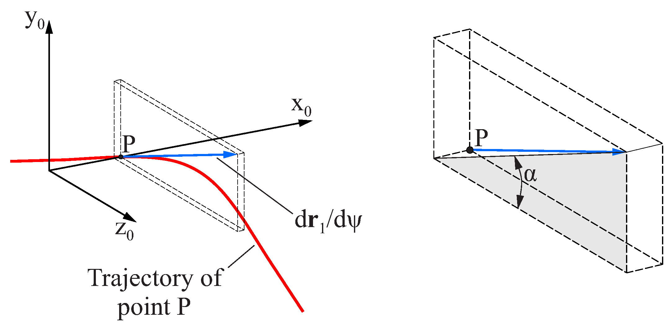
Appendix A. Calculation of the Reference Helix Angle of the Endodontic File
Figure A1 shows the trajectory of point
P of the grinding wheel surface, which is placed over the
axis of coordinate system
(which is coincident with axis
of coordinate system
) during the flute generating process. The position of point
P in coordinate system
is given by
Figure A1.
Definition of the helix angle .
Figure A1.
Definition of the helix angle .
Here,
is the external radius of the grinding wheel. The derivative of
with respect to
is a vector that is tangent to the trajectory described by that point during the generating process, which can be calculated using Equation (
12). Coordinate transformation from
to
describes such a vector in coordinate system
as
The helix angle
, which is defined as the angle between
and the projection of the previous vector onto the
plane, can be calculated as
This equation shows that the helix angle depends on
and
, whose values change with
throughout the length of the file, thus implying that the helix angle also changes throughout the length of the file. The reference helix angle
is defined as follows to simplify further calculations:
References
- Tabassum, S.; Zafar, K.; Umer, F. Nickel-titanium rotary file systems: What’s new? Eur. Endod. J. 2019, 4, 111–117. [Google Scholar] [CrossRef] [PubMed]
- ISO 3630-1:2008; Dentistry—Root-Canal Instruments—Part 1: General Requirements and Test Methods. International Organization for Standardization: Geneva, Switzerland, 2008.
- Al Jabbari, Y.S.; Tsakiridis, P.; Eliades, G.; Al-Hadlaq, S.M.; Zinelis, S. Assessment of geometrical characteristics of dental endodontic micro-instruments utilizing X-ray micro computed tomography. J. Appl. Oral Sci. 2012, 20, 655–660. [Google Scholar] [CrossRef]
- Dablanca-blanco, A.B.; Castelo-baz, P.; Miguéns-vila, R.; Álvarez-novoa, P.; Martín-biedma, B. Endodontic Rotary Files, What Should an Endodontist Know? Medicina 2022, 58, 719. [Google Scholar] [CrossRef] [PubMed]
- Cheung, G.S.; Darvell, B.W. Fatigue testing of a NiTi rotary instrument. Part 1: Strain-life relationship. Int. Endod. J. 2007, 40, 612–618. [Google Scholar] [CrossRef] [PubMed]
- Figueiredo, A.M.; Modenesi, P.; Buono, V. Low-cycle fatigue life of superelastic NiTi wires. Int. J. Fatigue 2009, 31, 751–758. [Google Scholar] [CrossRef]
- Vilaverde Correia, S.; Nogueira, M.T.; Silva, R.J.C.; Pires Lopes, L.; Braz Fernandes, F.M. Phase Transformations in NiTi Endodontic Files and Fatigue Resistance. In Proceedings of the 8th European Symposium on Martensitic Transformations, Prague, Czech Republic, 7–11 September 2009; p. 07004. [Google Scholar] [CrossRef]
- Dornelas Silva, J.; Lopes Buono, V.T. Effect of the initial phase constitution in the low-cycle fatigue of NiTi wires. SN Appl. Sci. 2019, 1, 1591. [Google Scholar] [CrossRef]
- Faus-Llacer, V.; Kharrat, N.; Ruiz-Sanchez, C.; Faus-Matoses, I.; Zubizarreta-Macho, A.; Faus-Matoses, V. The effect of taper and apical diameter on the cyclic fatigue resistance of rotary endodontic files using an experimental electronic device. Appl. Sci. 2021, 11, 863. [Google Scholar] [CrossRef]
- Kwak, S.; Ha, J.H.; Lee, C.J.; El Abed, R.; Abu-Tahun, I.; Kim, H.C. Effects of Pitch Length and Heat Treatment on the Mechanical Properties of the Glide Path Preparation Instruments. J. Endod. 2016, 42, 788–792. [Google Scholar] [CrossRef] [PubMed]
- Lee, M.H.; Versluis, A.; Kim, B.M.; Lee, C.J.; Hur, B.; Kim, H.C. Correlation between experimental cyclic fatigue resistance and numerical stress analysis for nickel-titanium rotary files. J. Endod. 2011, 37, 1152–1157. [Google Scholar] [CrossRef] [PubMed]
- Scattina, A.; Alovisi, M.; Paolino, D.S.; Pasqualini, D.; Scotti, N.; Chiandussi, G.; Berutti, E. Prediction of cyclic fatigue life of nickel-titanium rotary files by virtual modeling and finite elements analysis. J. Endod. 2015, 41, 1867–1870. [Google Scholar] [CrossRef]
- Ha, J.H.; Lee, C.J.; Kwak, S.W.; El Abed, R.; Ha, D.; Kim, H.C. Geometric optimization for development of glide path preparation nickel-titanium rotary instrument. J. Endod. 2015, 41, 916–919. [Google Scholar] [CrossRef] [PubMed]
- Ha, J.H.; Cheung, G.S.; Versluis, A.; Lee, C.J.; Kwak, S.W.; Kim, H.C. ’Screw-in’ tendency of rotary nickel-titanium files due to design geometry. Int. Endod. J. 2015, 48, 666–672. [Google Scholar] [CrossRef] [PubMed]
- Roda-Casanova, V.; Pérez-González, A.; Zubizarreta-Macho, A.; Faus-Matoses, V. Influence of Cross-Section and Pitch on the Mechanical Response of NiTi Endodontic Files under Bending and Torsional Conditions—A Finite Element Analysis. J. Clin. Med. 2022, 11, 2642. [Google Scholar] [CrossRef] [PubMed]
- de Arruda Santos, L.; López, J.B.; de Las Casas, E.B.; de Azevedo Bahia, M.G.; Buono, V.T.L. Mechanical behavior of three nickel-titanium rotary files: A comparison of numerical simulation with bending and torsion tests. Mater. Sci. Eng. C 2014, 37, 258–263. [Google Scholar] [CrossRef] [PubMed]
- Montalvão, D.; Shengwen, Q.; Freitas, M. A study on the influence of Ni-Ti M-Wire in the flexural fatigue life of endodontic rotary files by using Finite Element Analysis. Mater. Sci. Eng. C 2014, 40, 172–179. [Google Scholar] [CrossRef] [PubMed]
- Bonessio, N.; Pereira, E.; Lomiento, G.; Arias, A.; Bahia, M.; Buono, V.; Peters, O. Validated finite element analyses of WaveOne Endodontic Instruments: A comparison between M-Wire and NiTi alloys. Int. Endod. J. 2015, 48, 441–450. [Google Scholar] [CrossRef] [PubMed]
- Chien, P.Y.; Walsh, L.J.; Peters, O.A. Finite element analysis of rotary nickel-titanium endodontic instruments: A critical review of the methodology. Eur. J. Oral Sci. 2021, 129, e12802. [Google Scholar] [CrossRef] [PubMed]
- Roda-Casanova, V.; Zubizarreta-Macho, A.; Sanchez-Marin, F.; Alonso Ezpeleta, O.; Albaladejo Martinez, A.; Galparsoro Catalan, A. Computerized Generation and Finite Element Stress Analysis of Endodontic Rotary Files. Appl. Sci. 2021, 11, 4329. [Google Scholar] [CrossRef]
- Lask, J.T.; Walker, M.P.; Kulild, J.C.; Cunningham, K.P.; Shull, P.A. Variability of the Diameter and Taper of Size #30, 0.04 Nickel-Titanium Rotary Files. J. Endod. 2006, 32, 1171–1173. [Google Scholar] [CrossRef] [PubMed]
- Dallali, M.; Khalij, L.; Conforto, E.; Dashti, A.; Gautrelet, C.; Rodrigues Machado, M.; Souza de Cursi, E. Effect of geometric size deviation induced by machining on the vibration fatigue behavior of Ti-6Al-4V. Fatigue Fract. Eng. Mater. Struct. 2022, 45, 1784–1795. [Google Scholar] [CrossRef]
- Gutmann, J.L.; Gao, Y. Alteration in the inherent metallic and surface properties of nickel-titanium root canal instruments to enhance performance, durability and safety: A focused review. Int. Endod. J. 2012, 45, 113–128. [Google Scholar] [CrossRef] [PubMed]
- Heath, D.E.; Mooneyhan, J.A. Method of Fabricating an Endodontic Instrument. U.S. Patent 5527205, 18 June 1996. [Google Scholar]
- Heath, D.E. Endodontic Instrument Having Depth Calibrations and Method of Fabricating Same. U.S. Patent 5807106, 15 September 1998. [Google Scholar]
- Heath, D.E.; Mooneyhan, J. Endodontic Instument. U.S. Patent 5762541, 9 June 1998. [Google Scholar]
- Hoppe, W.; Schafer, E.; Tepel, J. Root Canal Instrument and Method for the Production Thereof. U.S. Patent 6702579, 9 March 2004. [Google Scholar]
- Master, R. Endodontic file grinding-GX3 machine. 2024. [Google Scholar]
- Taylor, T.; Vasquez, R.; Singleton, D.; Nightingale, J. Multi-Pass Grinding Method. World Patent WO 99/43469, 2 September 1999. [Google Scholar]
- Wagner, I.; Knee, M.; Nitsch, A. Method of Producing Endodontic Instruments. U.S. Patent 6890134, 10 May 2005. [Google Scholar]
- Lewis, P. Methods for Manufacturing Endodontic Instruments by Milling. U.S. Patent 2007/0116532 A1, 24 May 2007. [Google Scholar]
- Roda-Casanova, V.; Pérez-González, A.; Zubizarreta-Macho, A.; Faus-Matoses, V. Fatigue Analysis of NiTi Rotary Endodontic Files through Finite Element Simulation: Effect of Root Canal Geometry on Fatigue Life. J. Clin. Med. 2021, 10, 5692. [Google Scholar] [CrossRef]
- Berutti, E.; Chiandussi, G.; Gaviglio, I.; Ibba, A. Comparative Analysis of Torsional and Bending Stresses in Two Mathematical Models of Nickel-Titanium Rotary Instruments: ProTaper versus ProFile. J. Endod. 2003, 29, 15–19. [Google Scholar] [CrossRef] [PubMed]
- Diemer, F.; Calas, P. Effect of pitch length on the behavior of rotary triple helix root canal instruments. J. Endod. 2004, 30, 716–718. [Google Scholar] [CrossRef] [PubMed]
- Liang, Y.; Yue, L. Evolution and development: Engine-driven endodontic rotary nickel-titanium instruments. Int. J. Oral Sci. 2022, 14, 12. [Google Scholar] [CrossRef]
- Grande, N.; Castagnola, R.; Minciacchi, I.; Marigo, L.; Plotino, G. A review of the latest developments in rotary NiTi technology and root canal preparation. Aust. Dent. J. 2023, 68, S24–S38. [Google Scholar] [CrossRef] [PubMed]
Figure 1.
Creation of the blank of an endodontic file: main dimensions and shape. Geometries for (a) the raw material, (b) the initial shape of the tip, (c) the rounding of the tip and (d) the active part.
Figure 1.
Creation of the blank of an endodontic file: main dimensions and shape. Geometries for (a) the raw material, (b) the initial shape of the tip, (c) the rounding of the tip and (d) the active part.
Figure 2.
Schematic representation of the grinding process of the flutes of an endodontic file.
Figure 2.
Schematic representation of the grinding process of the flutes of an endodontic file.
Figure 3.
Schematic representation of the surface of the blank of an endodontic file, parameterized by the longitudinal coordinate v and the polar coordinate : (a) Three-dimensional representation and (b) cross section of the blank. For clarity, the blank is not drawn to a realistic scale.
Figure 3.
Schematic representation of the surface of the blank of an endodontic file, parameterized by the longitudinal coordinate v and the polar coordinate : (a) Three-dimensional representation and (b) cross section of the blank. For clarity, the blank is not drawn to a realistic scale.
Figure 4.
Schematic representation of the surface of a grinding wheel parametrized by the profile coordinate u and the polar coordinate : (a) Three-dimensional representation and (b) cross section of the grinding disk.
Figure 4.
Schematic representation of the surface of a grinding wheel parametrized by the profile coordinate u and the polar coordinate : (a) Three-dimensional representation and (b) cross section of the grinding disk.
Figure 5.
Coordinate systems used for the generation of the flutes of an endodontic file.
Figure 5.
Coordinate systems used for the generation of the flutes of an endodontic file.
Figure 6.
Cross-sections of the (a) blank, (b) flutes, and (c) endodontic file at an arbitrary longitudinal position.
Figure 6.
Cross-sections of the (a) blank, (b) flutes, and (c) endodontic file at an arbitrary longitudinal position.
Figure 7.
Definition of the approximation function .
Figure 7.
Definition of the approximation function .
Figure 8.
Parameterization of the geometry of the grinding wheel.
Figure 8.
Parameterization of the geometry of the grinding wheel.
Figure 9.
Lateral view for the case studies defined in
Table 2.
Figure 9.
Lateral view for the case studies defined in
Table 2.
Figure 10.
Cross-sections at different positions along the length of the endodontic files defined by the case studies defined in
Table 2.
Figure 10.
Cross-sections at different positions along the length of the endodontic files defined by the case studies defined in
Table 2.
Figure 11.
Analysis of the influence of on the geometry in case study B: (a–d) geometry of the cross-section at the middle of the active part for different values of and (e) evolution of the radius of the curvature of the cross-section with .
Figure 11.
Analysis of the influence of on the geometry in case study B: (a–d) geometry of the cross-section at the middle of the active part for different values of and (e) evolution of the radius of the curvature of the cross-section with .
Figure 12.
Cross-section at the middle of the active part for different variants of case study B, where a constant lead was varied, while all other design parameters remained constant.
Figure 12.
Cross-section at the middle of the active part for different variants of case study B, where a constant lead was varied, while all other design parameters remained constant.
Figure 13.
Cross-section at the middle of the active part for different variants of case study B, where the approximation at the beginning of the active part was varied, while all other design parameters remained constant.
Figure 13.
Cross-section at the middle of the active part for different variants of case study B, where the approximation at the beginning of the active part was varied, while all other design parameters remained constant.
Figure 14.
Partial view of the flute cross-section in the middle of the active part for case studies A, B, C, and D for variations in .
Figure 14.
Partial view of the flute cross-section in the middle of the active part for case studies A, B, C, and D for variations in .
Table 1.
Design parameters of the blank of the endodontic file according to
Figure 1. Parameters
,
,
, and
c were calculated from the other parameters.
Table 1.
Design parameters of the blank of the endodontic file according to
Figure 1. Parameters
,
,
, and
c were calculated from the other parameters.
| Parameter | Magnitude |
|---|
| Shaft diameter: | |
| Total length: | |
| Tip diameter: | |
| Auxiliary tip length: | |
| Length of active part: | |
| Tip length: | |
| Shaft length: | |
| Rounding radius of the tip: | |
| Diameter of active part transition: | |
| Taper of active part: c | |
Table 2.
Cases in this study defined by the parameters of the grinding process.
Table 2.
Cases in this study defined by the parameters of the grinding process.
| Case Study | A | B | C | D | E | F |
|---|
| Grinding wheel radius: (mm) | 20 | 20 | 20 | 20 | 20 | 20 |
| Tip radius: (mm) | | | | | | |
| Initial lead: (mm/rad) | | | | | | |
| Final lead: (mm/rad) | | | | | | |
| Initial distance: (mm) | | | | | | |
| Final distance: (mm) | | | | | | |
| Parabola coefficient: (mm−1) | | | | | | |
| Reference helix angle: (deg) | | | | | | |
| Grinding wheel angle: (deg) | | | | | | |
| Number of flutes: n | 3 | 3 | 3 | 3 | 3 | 3 |
| Disclaimer/Publisher’s Note: The statements, opinions and data contained in all publications are solely those of the individual author(s) and contributor(s) and not of MDPI and/or the editor(s). MDPI and/or the editor(s) disclaim responsibility for any injury to people or property resulting from any ideas, methods, instructions or products referred to in the content. |
© 2024 by the authors. Licensee MDPI, Basel, Switzerland. This article is an open access article distributed under the terms and conditions of the Creative Commons Attribution (CC BY) license (https://creativecommons.org/licenses/by/4.0/).


