Article

Synthesis and Structural Characterization of Dinitrogen Chromium Complexes with Triamidoamine Ligands Possessing Bulky Substituents, and Nitrogen Fixation by These Complexes

1
Graduate School of Engineering, Aichi Institute of Technology, 1247 Yachigusa, Yakusa-cho, Toyota 470-0392, Japan
2
Graduate School of Engineering, Nagoya Institute of Technology, Gokiso-cho, Showa-ku, Nagoya 466-8555, Japan
3
Department of Pharmaceutical Science, Suzuka University of Medical Science, Minami-Tamagaki-cho, Suzuka 513-8670, Japan
*
Author to whom correspondence should be addressed.
Inorganics 2026, 14(1), 24; https://doi.org/10.3390/inorganics14010024
Submission received: 12 December 2025 / Revised: 30 December 2025 / Accepted: 5 January 2026 / Published: 7 January 2026
(This article belongs to the Special Issue State-of-the-Art Inorganic Chemistry in Japan)

Abstract

Chromium complexes with triamidoamine derivatives bearing bulky substituents at the terminal positions of the ligands, tris(2-(3-pentylamino)ethyl)amine (H3LPen) and tris(2-dicyclohexylmethylaminoethyl)amine (H3LCy), are prepared: [{Cr(LPen)}2(μ-N2)] (1), [{CrK(LPen)(μ-N2)(Et2O)}2] (2), [CrCl(LPen)] (3), [Cr(LCy)] (4), [CrK(LCy)(μ-N2)(18-crown-6)(THF)] (5(THF)), and [CrCl(LCy)] (6). The preparation of these complexes is confirmed by X-ray diffraction analysis. Complexes 1, 2, and 5(THF) have coordinated dinitrogen molecules, with N–N bond lengths of 1.185(3), 1.174(9), and 1.162(3) Å, respectively. These lengths are significantly elongated compared to that of a free dinitrogen molecule (1.10 Å), indicating that the N2 ligands are activated. The ν(14N–14N) values of 1, 2, and 5(THF) are 1715 cm−1 for 1 (Raman, in solution), 1787, 1743 cm−1 for 2 (IR, in solid), and 1824 cm−1 for 5(THF) (IR, in solid), respectively. These values are markedly smaller than free nitrogen (2331 cm−1), confirming that the dinitrogen is interacting with the metal ions and is activated. The structures of 2 and 5(THF) in solution are also studied by 1H NMR and solution IR spectroscopies. 1H NMR spectra of these complexes reveal that the peaks of 2 and 5(THF) are observed in the diamagnetic region, whereas those for the other complexes (1, 3, 4, and 6) exhibit paramagnetic shifts. The reactions of these complexes with K[C10H8] and HOTf under N2 in THF yield hydrazine and a small amount of ammonia; however, they are not catalytic. The 1H NMR and IR spectra of the products obtained by reacting 1 or 3 with reductant K in THF under N2 atmosphere indicate that 2 is formed based on spectral agreement. Similarly, upon examining for 4 or 6, it is confirmed that a species similar to 5(THF) is generated.

1. Introduction

Nitrogen fixation primarily occurs in nature via nitrogenase enzymes, and industrially through the Haber–Bosch process [1,2]. However, as the Haber–Bosch process requires high-temperature, high-pressure reaction conditions and hydrogen derived from fossil fuels, active research is underway into nitrogen fixation under milder conditions, without hydrogen as the proton source [3]. Among various studies on nitrogen fixation, research on dinitrogen activation using transition metal complexes has been vigorously pursued since Schrock’s group first succeeded in catalytic nitrogen fixation using complexes centered on molybdenum, the metal present in nitrogenase enzymes [4,5,6,7,8,9,10,11,12,13,14,15,16,17,18,19,20,21,22,23,24,25,26,27,28,29].
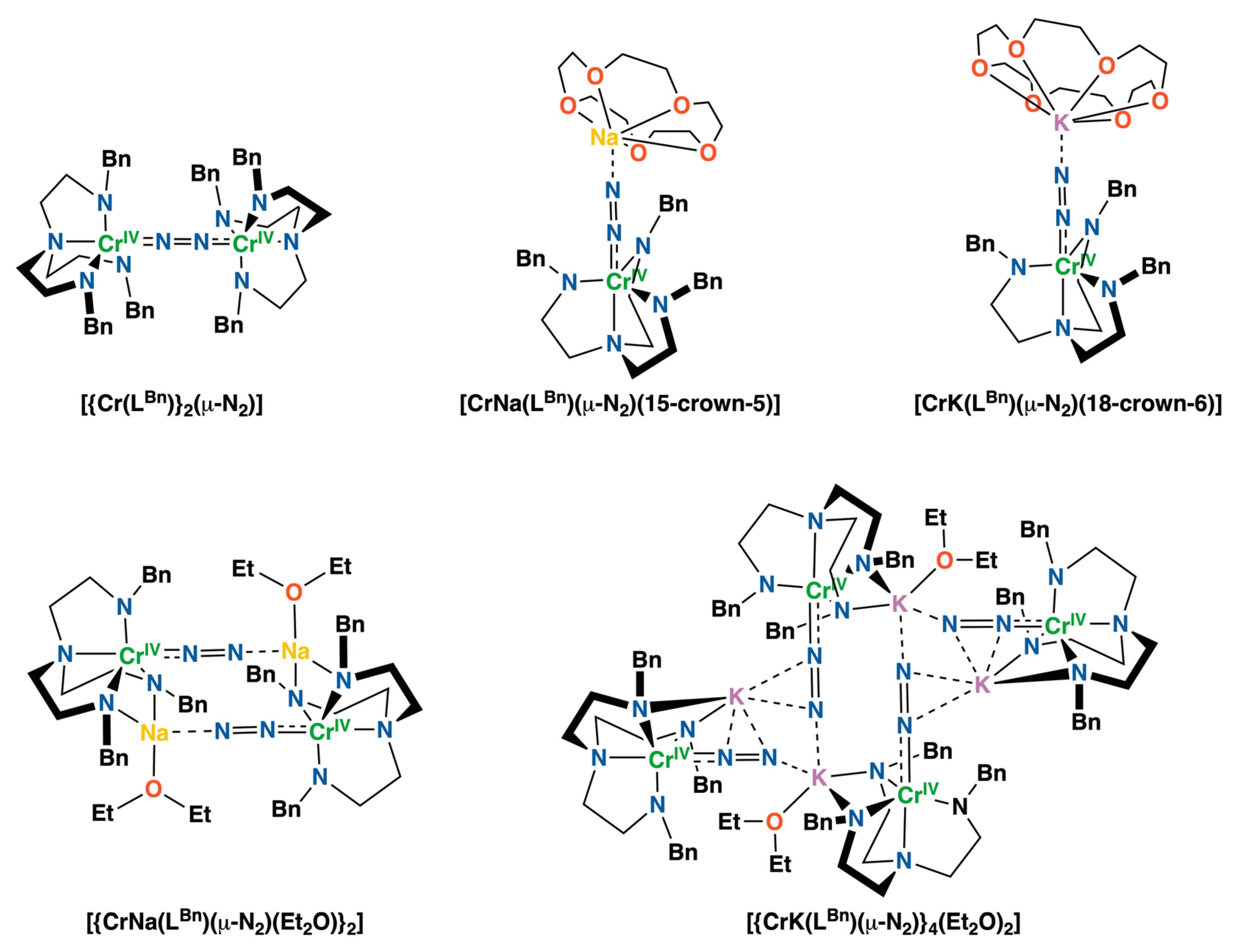
Group VI metals such as molybdenum and tungsten are frequently employed as representative transition-metal complexes for dinitrogen activation, and highly interesting studies have been reported to date [12,13,16,18,20,29,30,31,32,33,34,35,36,37,38,39,40,41]. However, research utilizing chromium, which also belongs to Group VI, has been scarcely conducted; consequently, studies on the activation of dinitrogen molecules using chromium are highly significant [29,42,43,44,45,46,47,48,49,50,51,52,53,54,55,56,57,58,59,60,61,62,63,64,65,66,67,68,69,70]. Among these, although they are few in number, dinitrogen activation reactions using chromium complexes have been reported, with some reporting the production of ammonia, hydrazine, tris(trimethylsilyl)amine (N(SiMe3)3), or diazenido and hydrazido complexes [44,46,47,48,49,52,55,56,58,59,60,61,62,63,64,65,66,67,68,69,70]. The oxidation states of the chromium ions in these chromium–dinitrogen complexes are primarily 0, I, II, or III. However, recently, dinitrogen complexes in which the formal oxidation state of the chromium ion is –I have been reported [63]. We also synthesized several dinitrogen complexes containing Cr(IV) ions, which had not previously been used to activate dinitrogen, and reported that these complexes react with a proton source to produce ammonia and hydrazine (Figure 1) [71]. However, as numerous unknowns remain in research concerning dinitrogen activation using chromium ions, further studies on dinitrogen activation employing diverse chromium ions are required.
Previously, we synthesized and structurally characterized dinitrogen chromium(IV) complexes bearing triamidoamine ligands (Figure 1) and investigated their nitrogen fixation reactions, yielding ammonia and hydrazine. However, the terminal substituent of the triamidoamine ligand was limited to a benzyl group. Therefore, in this study, the terminal substituents of the ligands were changed to the bulky tren derivatives, tris(2-(3-pentylamino)ethyl)amine (H3LPen) and tris(2-dicyclohexylmethylaminoethyl)amine (H3LCy), and the effect of these substituents on the chemical properties and reactivities of dinitrogen was investigated.

2. Results and Discussion

2.1. Preparation of Bulky Tren Ligands and Their Chromium Complexes, 1, 2, 3, 4, 5(THF), and 6

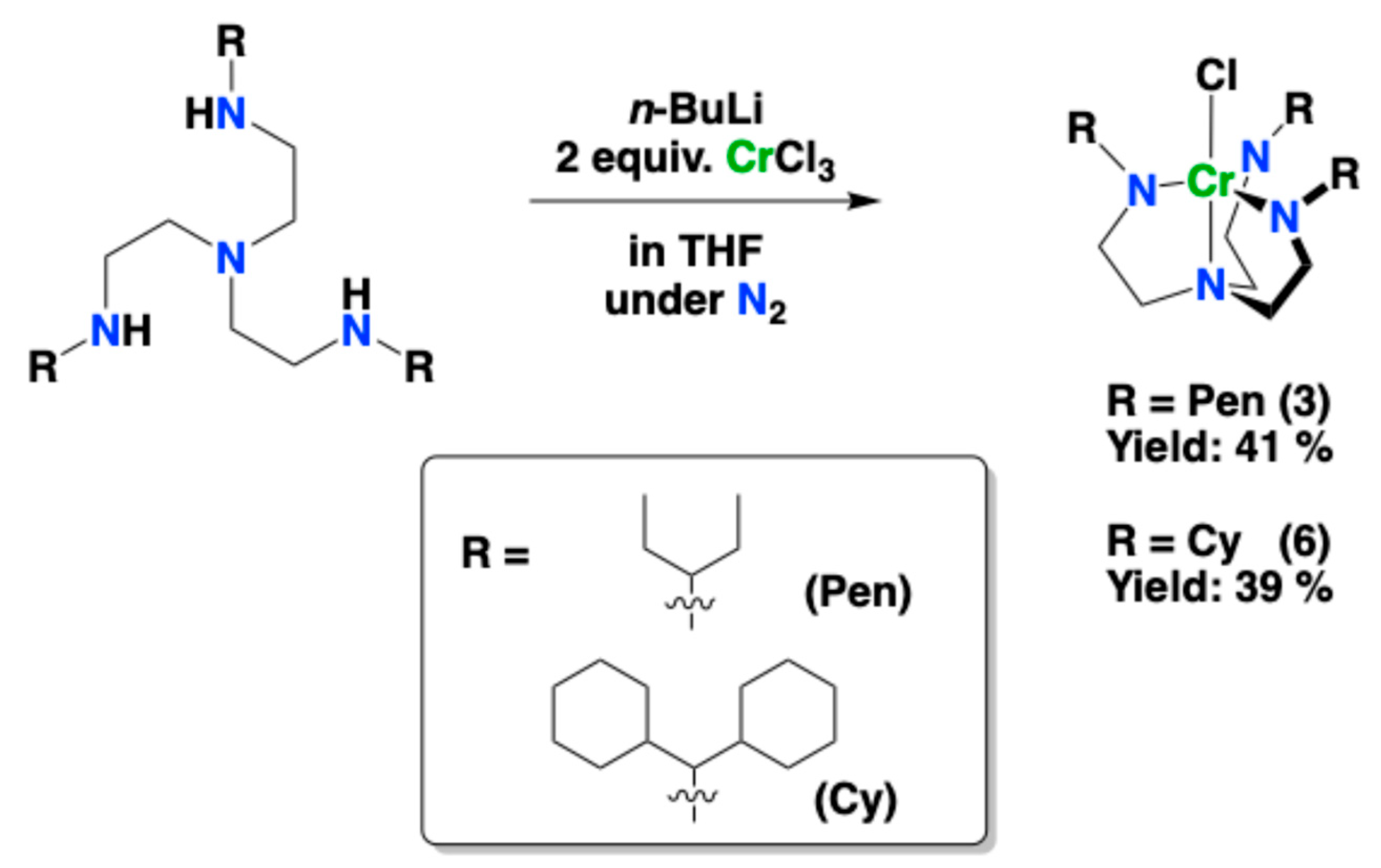
Two tren derivatives with bulky substituents, H3LPen and H3LCy, were synthesized by the previously reported method, and several chromium complexes were prepared using these ligands [72]. These tren derivatives were lithiated with three equivalents of n-BuLi, yielding Li3[LPen] and Li3[LCy], respectively.
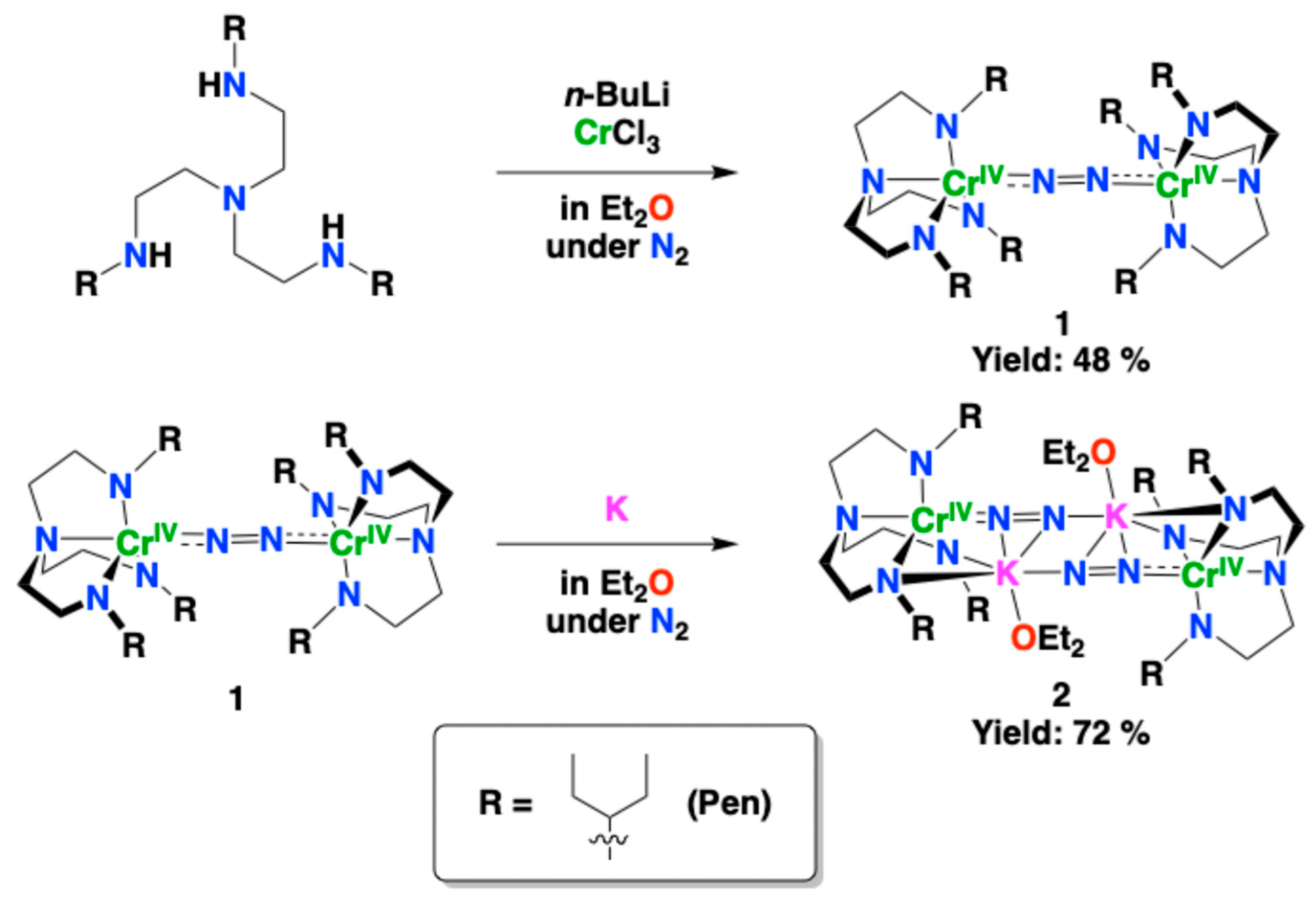
Li3[LPen] reacted with CrCl3 in Et2O under N2 to yield a dinitrogen dichromium complex, [{Cr(LPen)}2(μ-N2)] (1) (Scheme 1). Recrystallization of complex 1 from an Et2O solution gave dark red crystals. Reacting complex 1 with 10 equivalents of K metal in Et2O under a N2 atmosphere yielded a dichromium complex containing two dinitrogen ligands and two K+ ions, [{CrK(LPen)(μ-N2)(Et2O)}2] (2) (Scheme 1). Recrystallization of complex 2 from the Et2O solution gave dark green crystals. A Cr(IV) complex bearing Cl ions, [CrCl(LPen)] (3), was also synthesized as a Cr(IV) complex without dinitrogen ligands by the previously reported method [71].
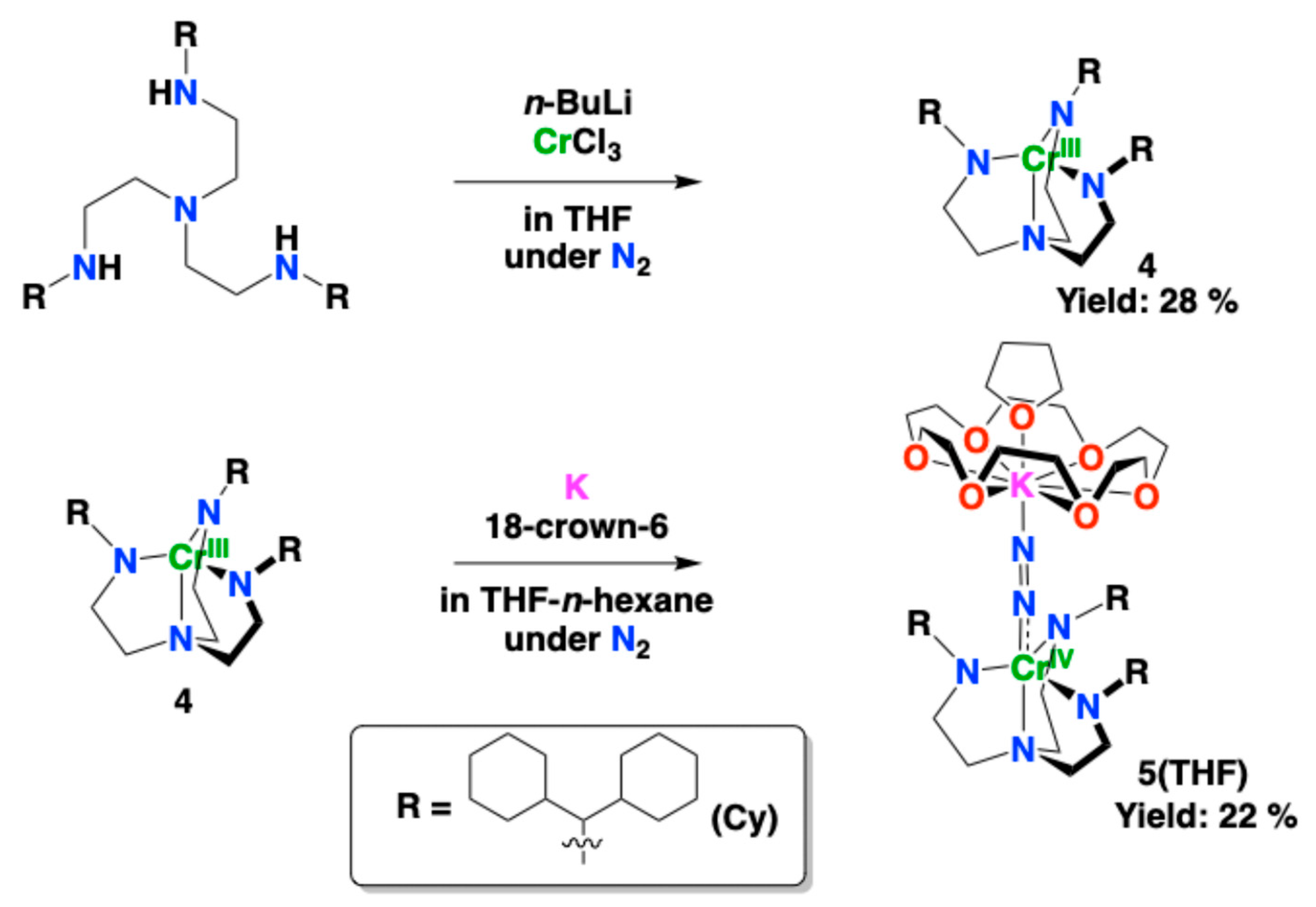
On the other hand, reacting Li3[LCy] with CrCl3 in THF under N2 afforded a mononuclear chromium complex, [Cr(LCy)] (4), which lacks a dinitrogen ligand. Recrystallizing complex 4 from an n-hexane solution yielded dark red crystals. Reacting complex 4 with K metal and 18-crown-6 ether in THF under a N2 atmosphere gave a dinitrogen chromium complex containing a K+ ion, [CrK(LCy)(μ-N2)(18-crown-6)(THF)] (5(THF)) (Scheme 2). A Cr(IV) complex bearing a Cl ion, [CrCl(LCy)] (6), was also synthesized as a Cr(IV) complex without dinitrogen ligands by the same method as 3 (Scheme 3). Recrystallization of complex 6 from a cyclopentylmethyl ether solution yielded dark violet crystals.

2.2. Crystal Structures of Complexes 1, 2, 4, and 5(THF)

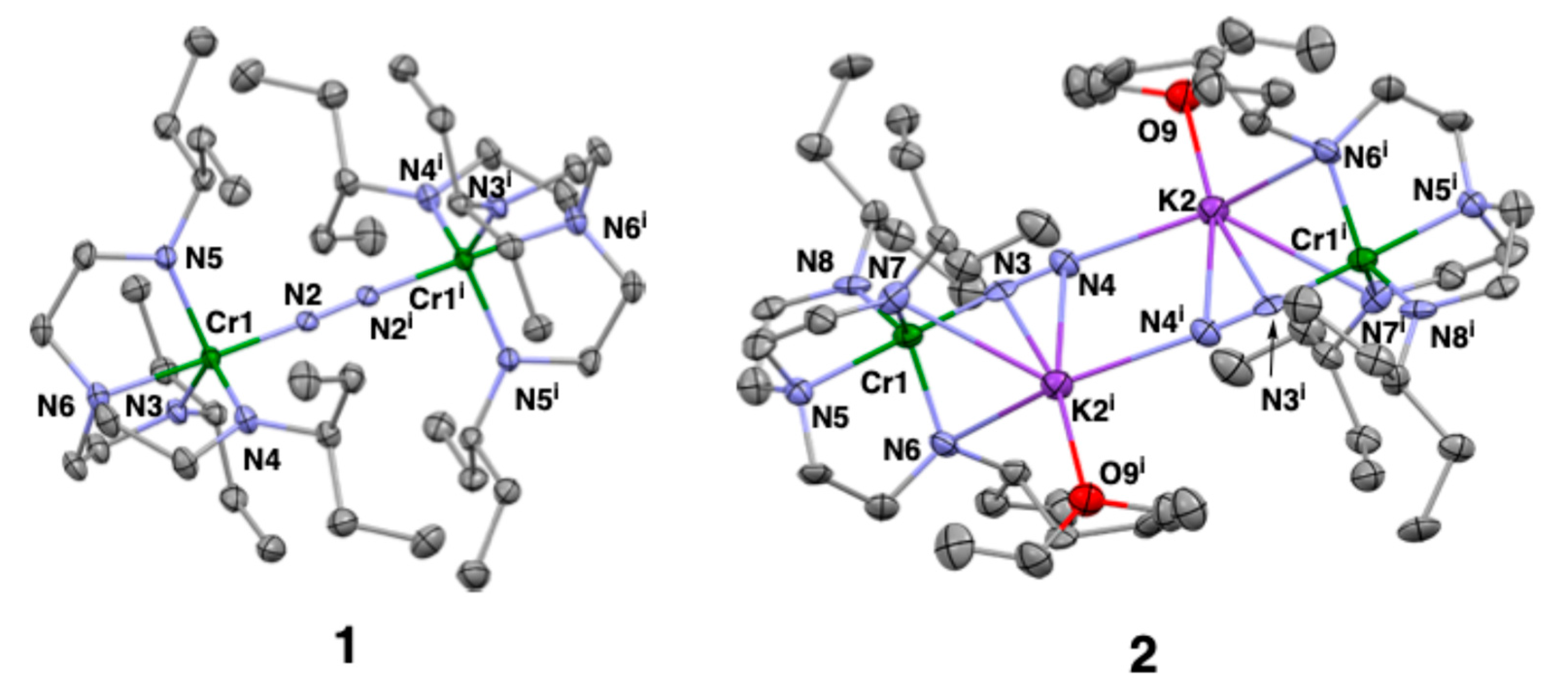
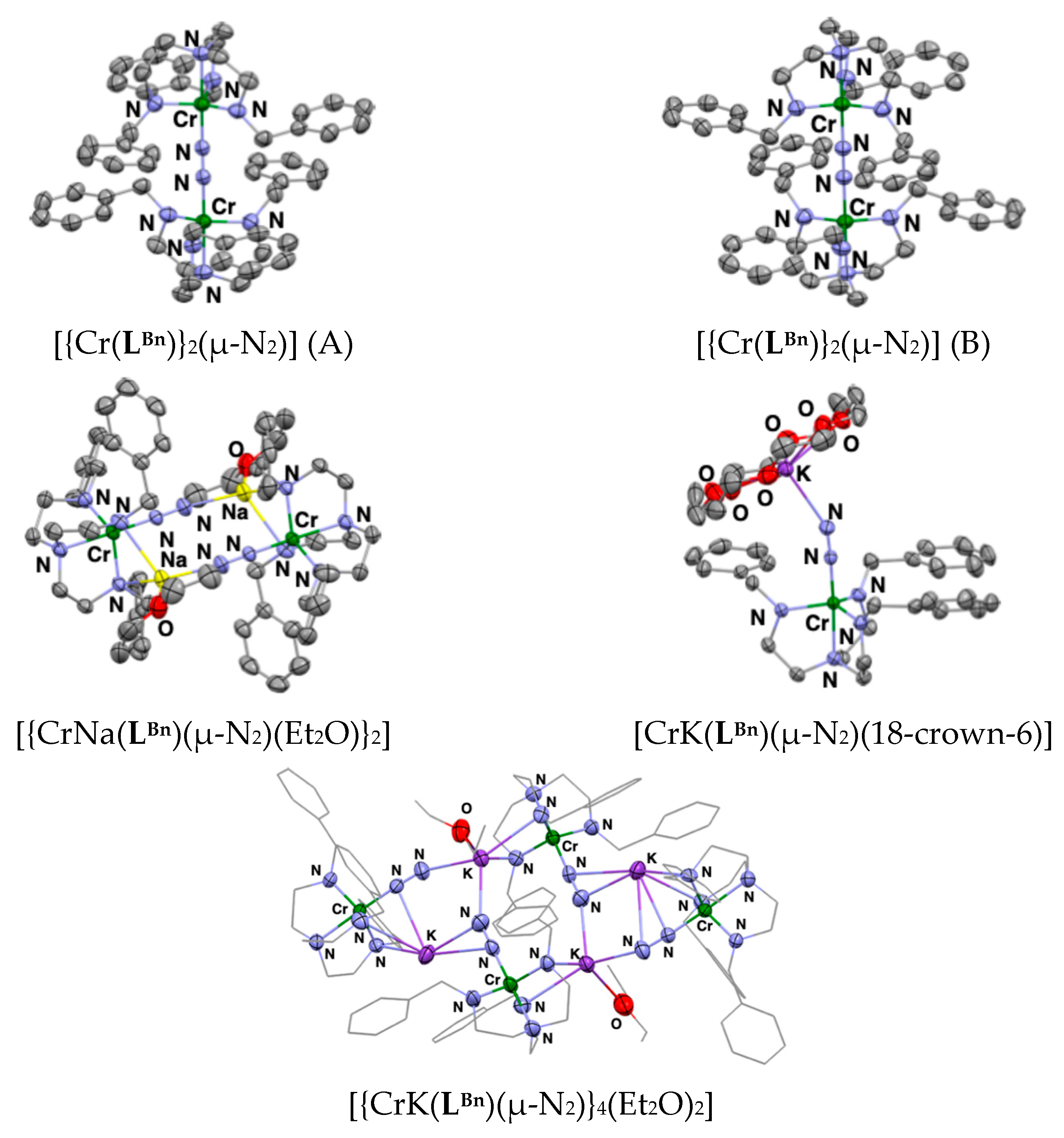
The crystal structures of 1 and 2 are shown in Figure 2 together. The crystal parameters and the selected bond lengths and angles of 1 and 2 are listed in Table S1 and Table 1, respectively. Complex 1 is a dichromium complex possessing a dinitrogen ligand as the bridging ligand. Each Cr atom forms a trigonal bipyramidal geometry with three amido nitrogen atoms of [LPen]3− located on a trigonal plane and another amino nitrogen of [LPen]3− and a dinitrogen molecule at the axial positions. The N–N bond length is 1.185(3) Å, which is significantly elongated compared to a free nitrogen molecule (1.10 Å) [20], and is almost identical to those (1.188(4) and 1.185(7) Å) of the previously reported complex bearing a benzyl group as the substituent on the triamidoamine ligand ([LBn]3−), [{Cr(LBn)}2(μ-N2)] (Figure 3) [71]. The Cr–NN2 bond length of 1 is 1.8468(15) Å, which is longer than those (1.805(2) and 1.804(4) Å) of the previously reported dichromium complex with benzyl groups. This is thought to be due to the increased steric repulsion resulting from the pentyl group having greater spatial extension than the benzyl group. Therefore, the Cr–NN2 bond of 1 is considered to possess the properties of a weak multiple bond. Furthermore, the N–N distance is shorter than that (1.226(3) Å) of the dinitrogen–divanadium complex with the same triamidoamine ligand [72]. This is thought to be due to the difference in the back-donating ability of the metal ions to the dinitrogen ligand. That is, when the π-back-donation is large, electrons enter the antibonding orbitals of dinitrogen from the metal, weakening the N–N bond and then reducing the ν(N–N) stretching vibration. Comparing dinitrogen–dichromium complex 1 and the dinitrogen–divanadium complex [72], the ν(N–N) stretching vibration in the dichromium complex is 1715 cm−1, while in the divanadium complex it is 1412 cm−1, indicating the divanadium complex is more weakened. This indicates that the π-back-donation is larger in the dinitrogen–divanadium complex than in the dinitrogen–dichromium complex. Consequently, the M–NN2 distance in the divanadium complex should be shorter than in the dichromium complex. Indeed, the V–NN2 bond distance (1.7935(14)) Å is shorter than the Cr–NN2 bond (1.8468(15) Å), clearly reflecting the difference in the π-back-donating ability of the metal ions.
Complex 2 is a dinuclear Cr complex containing two potassium ions and two dinitrogen molecules. Each Cr atom forms a trigonal bipyramidal structure coordinated with the ligand [LPen]3− and dinitrogen molecule, similar to complex 1. The dinitrogen ligand formed a bridge between the chromium and the two potassium ions, coordinating with one potassium ion in an end-on mode and with the other potassium ion in a side-on mode. The N–N bond length in 2 is 1.174(9) Å, showing a tendency to be shorter than that of 1. This N–N bond length is longer than that (1.1624(19) Å) observed in the previously reported complex [{CrNa(LBn)(µ-N2)(Et2O)}2] (Figure 3) [71], which possesses a similar structure with terminal substituents of a benzyl group and a sodium ion, but with a potassium ion substituted instead. This is thought to be due to the large ionic radius of the potassium ion (1.37–1.64 Å) in comparison with the sodium ion (0.99–1.39 Å) [73]. The potassium ion sandwiched between the two amido nitrogen atoms of the ligand migrates towards the dinitrogen ligand, resulting in one dinitrogen ligand forming coordination bonds with two potassium ions. The Cr–NN2 bond length is 1.762(8) Å, indicating that 2 has a stronger multiple bond character than 1.
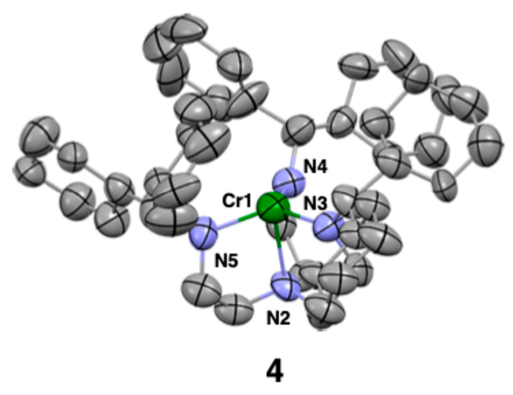
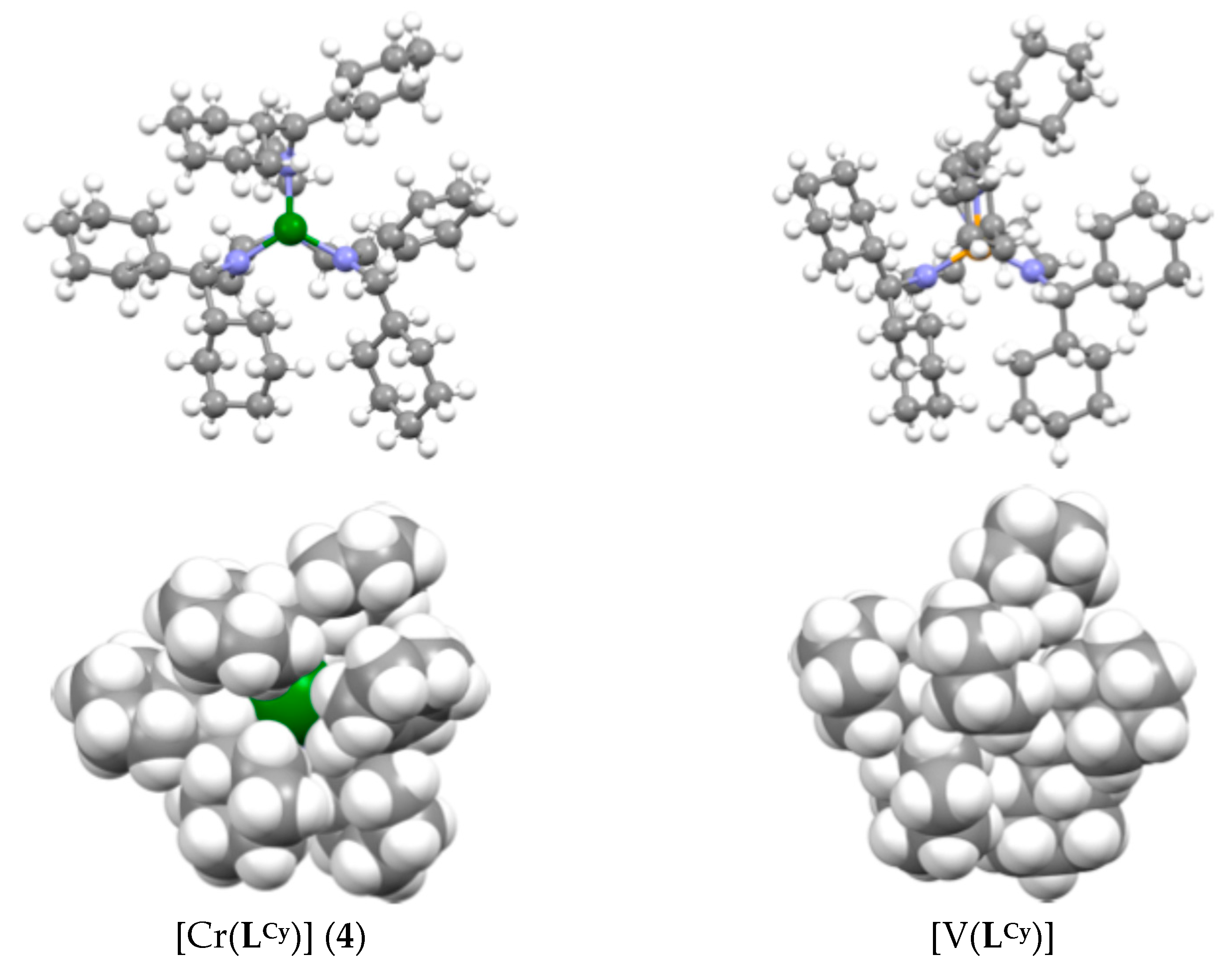
For complex 4, synthesized using Li3[LCy], accurate results could not be obtained from X-ray crystal structure analysis. However, because the approximate structure was already known, 25% probability ellipsoids are displayed for the carbon, nitrogen, and chromium atoms in the ORTEP display of 4 (Figure 4). The crystal parameters and the selected bond lengths and angles of 4 are listed in Tables S1 and S2, respectively. Complex 4 revealed a trigonal monopyramidal coordination geometry, with the axial position being vacant. A chromium complex with a similar structure was previously reported by Filippou’s group [74]. Also, the previously reported vanadium complex with the same ligand, [V(LCy)] [72], also possessed an axial vacancy, but one cyclohexane ring was positioned axially, thereby preventing the coordination of other molecules. In contrast, the cyclohexane ring in complex 4 is not located axially, resulting in a structure with many gaps, as shown in Figure 5. Consequently, complex 4 is very air sensitive.
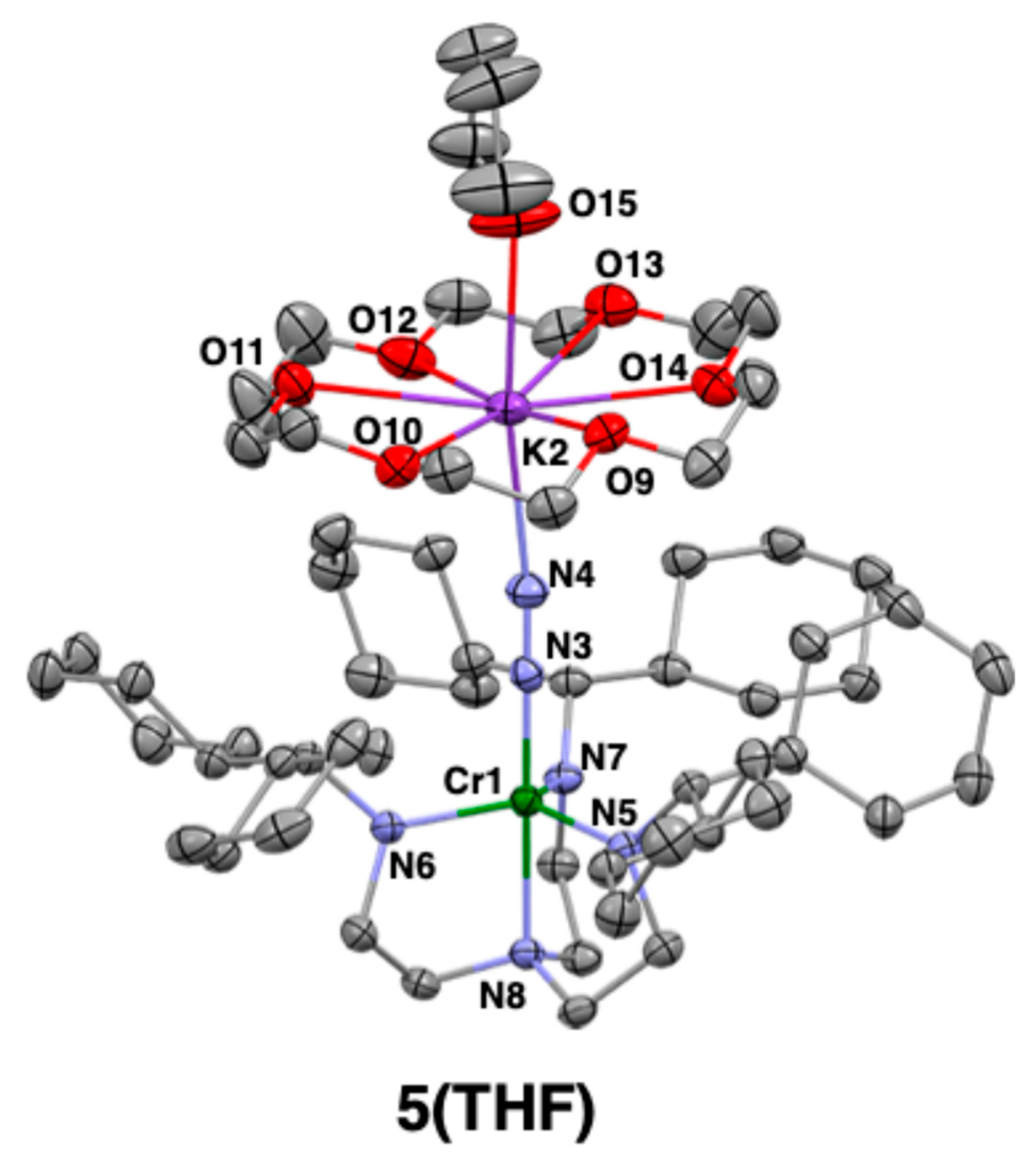
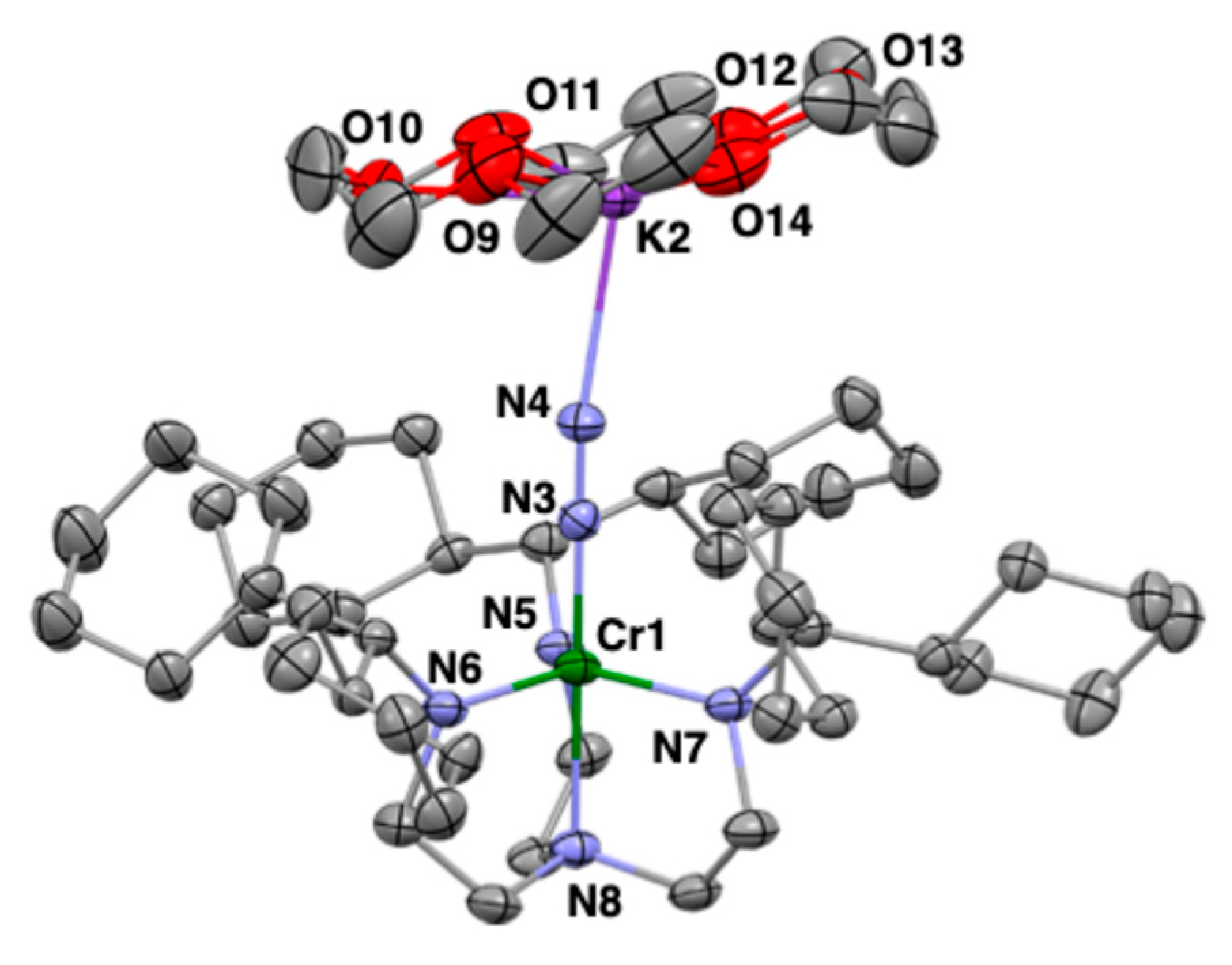
Next, reacting complex 4 with metallic potassium and 18-crown-6 ether under N2 yielded the dinitrogen chromium complex 5(THF). Fortunately, a single crystal of 5(THF) was obtained from THF-n-hexane solution and analyzed by X-ray diffraction. The crystal structure is shown in Figure 6, and the crystal parameters and selected bond lengths and angles are listed in Table S1 and Table 2, respectively. The Cr complex adopts a trigonal bipyramidal structure, forming a trigonal plane with three amido nitrogen atoms of the [LCy]3− ligand, with the axial positions occupied by another amine nitrogen of the [LCy]3− ligand and a dinitrogen ligand. The opposite side of the dinitrogen ligand is bonded to a potassium ion coordinated by an 18-crown-6 ether ligand from the planar side and a THF molecule from the apical position, resulting in the N2 ligand forming a bridge between the chromium and potassium atoms, with an N–N bond length of 1.162(3) Å. The N–N bond length is slightly shorter than that (1.167(2) Å) of the previously reported chromium–dinitrogen complex containing a benzyl group, [CrK(LBn)(μ-N2)(18-crown-6)] (Figure 3) [71]. The Cr–NN2 and K–NN2 bond lengths of 5(THF) were 1.761(2) and 2.647(2) Å, respectively. These bond lengths were also shorter compared with the Cr–NN2 (1.7678(15) Å) and K–NN2 bond lengths (2.7822(16) Å) of the previously reported chromium complex [CrK(LBn)(μ-N2)(18-crown-6)] [71].

2.3. Crystal Structures of Complexes 3 and 6

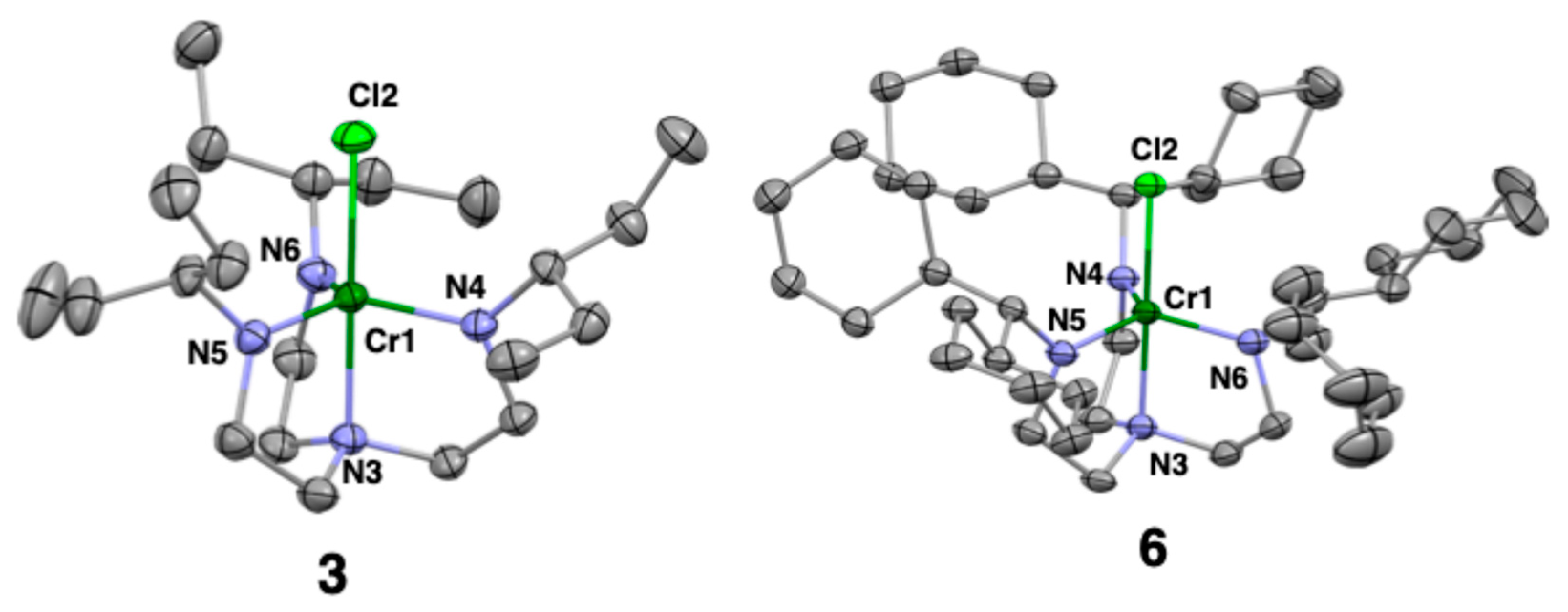
The crystal structure of the CrIVCl complex with [LPen]3− or [LCy]3−, 3 or 6, is shown in Figure 7, and the crystal parameters and selected bond lengths and angles are listed in Table S1 and Table 3, respectively. The crystal structural data for 3 have been reported previously [71], and its molecular structure is also shown in Figure 7 of this paper. The coordination structures around the Cr ion in 3 and 6 both have a trigonal bipyramidal geometry. The three amine nitrogen atoms of the bulky ligand are arranged in a triangular plane around the Cr atom, while another amido nitrogen atom of the ligand and the chlorine atom are positioned axially. The Cr–Cl bond lengths in 3 and 6 are almost the same (2.3145(6) Å for 3, 2.3147(7) Å for 6). However, comparing the Cr–Namine and Cr–Namido bond lengths in these complexes, the Cr–Namine (2.0446(16) Å) and Cr–Namido (av) (1.866 Å) of 3 are shorter than those (Cr–Namine 2.088(2) Å, Cr–Namido (av) 1.8828 Å) in 6. This is thought to be due to the steric repulsion between the terminal substituents of the ligand in 6 being greater than that in 3. Previously, Filippou’s group has reported a similar chromium complex with terminal trimethylsilyl groups on the triamidoamine ligand; however, no structural trend could be found among these three Cr(IV)–Cl complexes [74].

2.4. Raman and IR Spectra of 1, 2, and 5(THF)

To investigate the reactivity of the dinitrogen molecule bound to the Cr atom in complexes 1, 2, and 5(THF), vibrational spectroscopic measurements were carried out on them. Complex 1 was studied by Raman spectroscopy in cyclohexane solution using laser light excited at 532 nm. The ν(14N–14N) stretching vibration of complex 1 was detected at 1715 cm−1. When 15N2 was used in the reaction instead of 14N2, the ν(15N–15N) stretching vibration was obtained at 1651 cm−1, exhibiting an ideal isotope shift (Figure S1). This value is significantly smaller than free dinitrogen (2331 cm−1) [20], clearly indicating that the dinitrogen ligand has been activated, but it is larger than the ν(14N–14N) stretching vibration (1412 cm−1) of the dinitrogen divanadium complex possessing the same triamidoamine ligand [72]. As mentioned in Section 2.1, this is also reflected in the N–N bond length and is thought to be due to the fact that the back-donation from the metal to the dinitrogen ligand is smaller for Cr than for V.
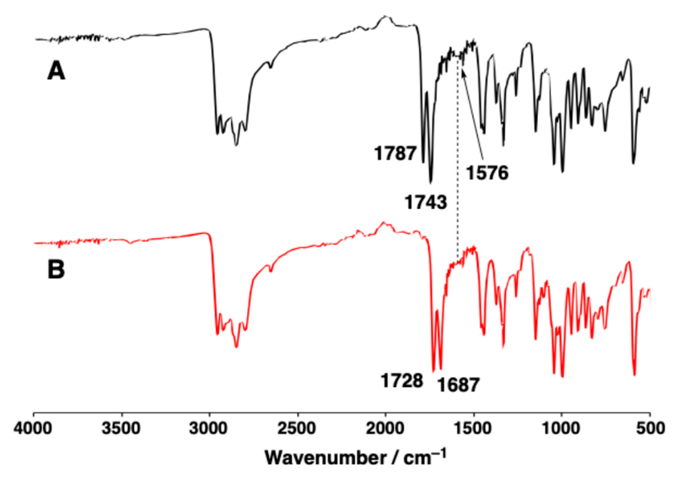
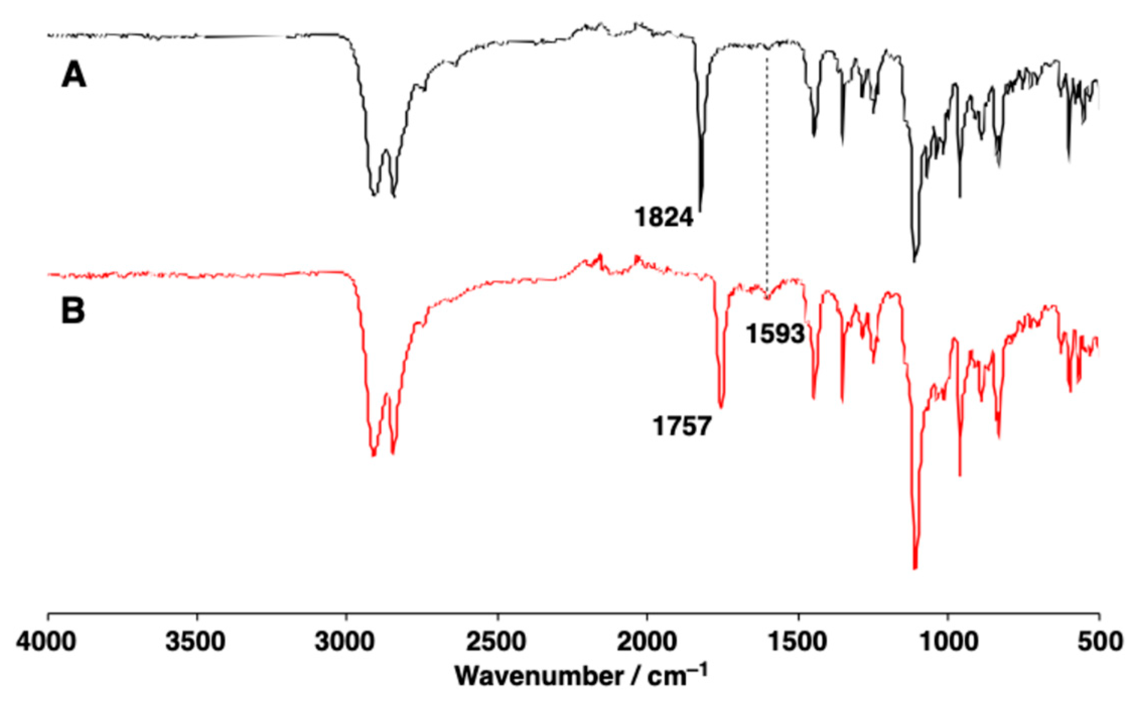
Complexes 2 and 5(THF), which possess dinitrogen ligands bridging between the chromium ion and potassium ion, were investigated by IR spectroscopy (ATR method). The peaks assignable to ν(14N–14N) stretching vibration were observed as two bands at 1787 and 1743 cm−1 for 2, and as one band at 1824 cm−1 for 5(THF) (Figure 8 and Figure 9). When 15N-labeled dinitrogen chromium complexes of 2 and 5, [{CrK(LPen)(μ-15N2)(Et2O)}2] (2′) and [CrK(LCy)(μ-15N2)(18-crown-6)(THF)] (5′(THF)), were employed, these peaks shifted to 1728 and 1687 cm−1 for 2′ and to 1757 cm−1 for 5′(THF). These findings indicate that the stretching vibration frequencies of dinitrogen molecules have shifted to the lower-energy side due to the isotope effect, and the presence of two peaks in 2 suggests that dinitrogen exists in two different bridging modes between Cr and K. In the previously reported complex [{CrNa(LBn)(μ-N2)(Et2O)}2], which possesses a sodium ion instead of a potassium ion and features benzyl groups at the terminals of the triamidoamine ligand, the ν(14N–14N) stretching vibration was observed at 1813 cm−1 [71]. Therefore, based on the crystal structure of 2 described in Section 2.2 (Figure 2), the two peaks detected at 1787 and 1743 cm−1 for 2 are considered to correspond to a dinitrogen ligand bridged by a chromium ion and one potassium ion in an end-on mode, and a dinitrogen ligand bridged by a chromium ion and two potassium ions in end-on and a side-on modes, respectively.
The ν(N–N) stretching vibration (1824 cm−1) of 5(THF) was observed in a higher-energy region than that (1807 cm−1) of the previously reported complex [CrK(LBn)(μ-N2)(18-crown-6)] [71]. This is consistent with the elongated N–N bond lengths of the respective complexes being 1.162(3) Å for 5(THF) and 1.167(2) Å for [CrK(LBn)(μ-N2)(18-crown-6)], with complex 5(THF) exhibiting a slightly shorter bond length [71].

2.5. IR Spectra of 2 and 5(THF) in Solution

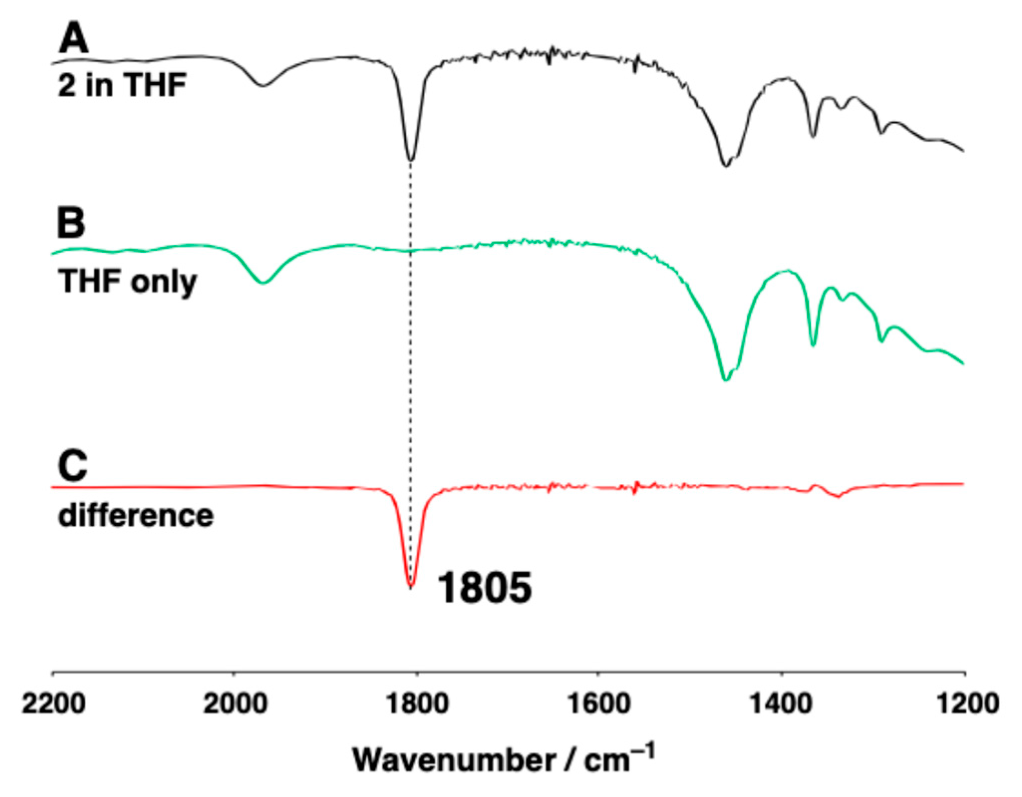
To further elucidate the structures of 2 and 5(THF) in solution, the IR spectra were measured in THF and toluene. Those of 2 are shown in Figure 10 and Figure S2, respectively, and those of 5(THF) are shown in Figure 11 and Figure S3, respectively. The ν(N–N) stretching vibration peaks of 2 appeared as a single peak at 1805 cm−1 in THF and at 1790 cm−1 in toluene, respectively. However, in the solid state, as mentioned above, two peaks (1787 and 1743 cm−1) were observed in the lower energy region compared to the solution state. This finding suggests that the dinitrogen ligand in solution is bridging between the K+ ion and the Cr(IV) ion in end-on fashion, although the dinitrogen ligands in the crystal structure of 2 involved in both end-on and side-on fashions.
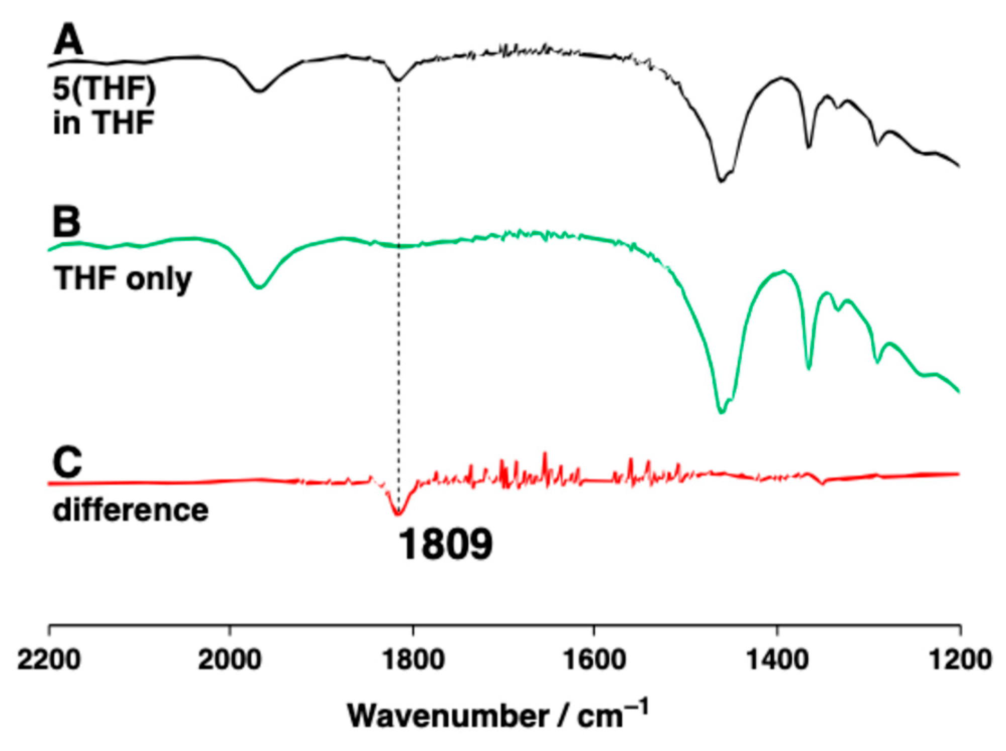
On the other hand, for complex 5(THF), the ν(N–N) stretching vibration peak was observed as a single peak at 1809 cm−1 in THF (Figure 11) and at 1805 cm−1 in toluene (Figure S3), respectively, both of which were observed in lower energy side compared to that (1824 cm−1) in the solid state. As explained in Section 2.6 below, in toluene or THF solution, the THF ligand is thought to be removed from complex 5(THF), forming a THF-free complex 5.

2.6. 15N NMR Spectra of 2 and 5(THF)

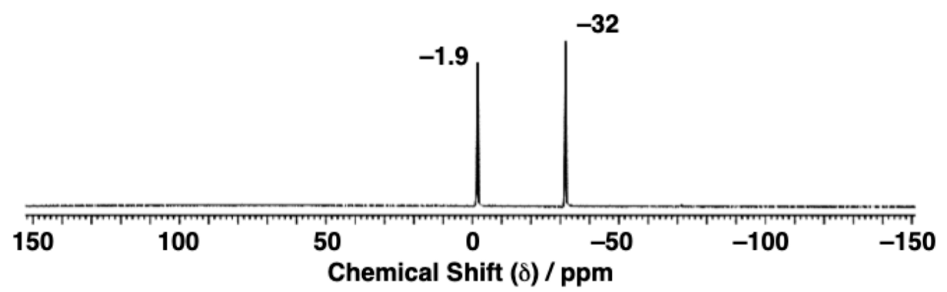
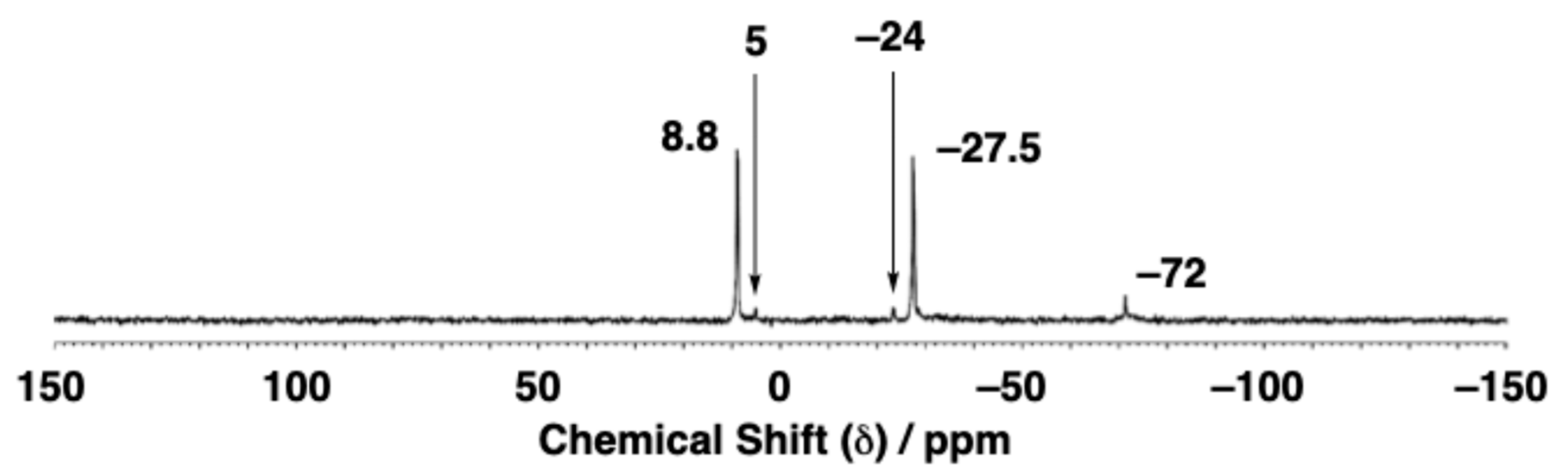
To further examine the coordination mode of the dinitrogen molecules with the Cr atom in complexes 2 and 5(THF) in solution, their 15N NMR spectra were measured in C6D6 solution using complexes 2′ and 5′(THF) with 15N-labeled N2. The peaks of 15N-labeled dinitrogen ligands in both complexes were observed at −1.9 and −32 ppm for 2′ (Figure 12), and at 8.8 and −27.5 ppm for 5′(THF) (Figure 13). The peaks in low and high magnetic field regions for 2′ and 5′(THF) are consistent with those of the previously reported chromium complexes [{CrK(LBn)(μ-N2)}4(Et2O)2] (1.79 and −71.26 ppm) [71] and [CrK(LBn)(μ-N2)(18-crown-6)] (4.79 and −25.22 ppm) [71], so they were assigned to the Nα atom bonded to Cr on the low magnetic field side of the coordinated N2, and to the Nβ atom on the opposite side on the high magnetic field side, respectively. The two peaks in complex 2′ both exhibited small shoulder peaks on the lower magnetic field side. To investigate the reason for this, spectra were acquired by varying the number of scans (10,000, 20,000, 30,000, 40,000, and 50,000 scans). It was confirmed that the shoulder peaks gradually changed from a small double peak to a shoulder peak (Figure S4). Considering the IR spectral behavior of 2 described above, these peaks are likely to originate from species in which the dinitrogen ligand coordinates to the potassium ion in a side-on mode. Therefore, these spectra suggest that species in which the dinitrogen ligand coordinates to the potassium ion in a side-on mode are thermally unstable in solution and gradually transform into the end-on mode species.
Incidentally, in the spectrum of 5′(THF) [CrK(LCy)(μ-15N2)(18-crown-6)(THF)], small peaks were observed at 5, −24, and −72 ppm. The peak at −72 ppm is thought to be due to the amine N atoms of the ligand [LCy]3−, because it exhibits the largest peak area among the three peaks. A single crystal was accidentally precipitated from the NMR sample tube used for the 15N NMR spectral measurement of 5′(THF), so its crystal structure analysis was carried out. As a result, the THF ligand coordinated to the potassium ion in 5′(THF) was removed, forming the complex [CrK(LCy)(µ-15N2)(18-crown-6)] (5′). The N–N bond length of the dinitrogen ligand in 5′ was slightly elongated from 1.162(3) Å to 1.170(4) Å as compared with that in 5′(THF) (Figure 14, Table 2 and Table 4). This elongation of the 5′ N–N bond is consistent with the fact that the N–N stretching vibration of 5 (1813 cm−1) obtained from a C6D6 solution of 5(THF) is shifted to a lower-energy region compared to that of 5(THF) (Figures S5 and S6). Furthermore, considering that most of the THF ligands in 5(THF) are removed even in a THF solution, the fact that stretching vibrations in the low-energy region were observed in solution, as mentioned in Section 2.5 above, is consistent with the elongation of the N–N bond distance in the crystal structure. Therefore, the strong peaks at 8.8 and −27.5 ppm in the 15N NMR spectrum (Figure 13) of 5′(THF) are thought to originate from the N2 ligand of complex 5′ without bound THF. Furthermore, the minor peaks at 5 ppm and −24 ppm in Figure 13 are considered to originate from the N2 ligand of a small amount of 5′(THF), in which THF is coordinated to the potassium ion.

2.7. 1H NMR Spectra of 16

The 1H NMR spectrum of 1 in C6D6 exhibited paramagnetic shifts with broadened peaks at 12, 5, 0.8, and −38 ppm (Figure S7). The magnetic moment (μeff) of 1 in solution was measured by the Evans method and estimated to be μeff = 2.87 μB at room temperature. This result suggests that the spin state of 1 is S = 1, similar to that of [{Cr(LBn)}2(μ-N2)], as reported previously [71]. On the other hand, the peaks in the 1H NMR spectra of 2 (Figure S8) and 5(THF) (Figure S11) in C6D6 were observed as simple spectra in the diamagnetic region, despite the complexity of their crystal structures. These findings clearly indicate that complexes 2 and 5(THF) exhibit high symmetry, specifically C3 symmetry, in solution. As mentioned above, in C6D6, most of the THF ligands in 5(THF) were released, likely forming [CrK(LCy)(μ-14N2)(18-crown-6)] (5). And these are also consistent with those for the previously reported complexes [{CrNa(LBn)(μ-N2)}2] and [CrK(LBn)(μ-N2)(18-crown-6)], suggesting a very strong antiferromagnetic interaction between the Cr ion and the N2 ligand with an S = 0 spin state [71]. Furthermore, the 1H peaks of ligands H3LPen and H3LCy were also observed in the 1H NMR spectra of 2 and 5(THF) (Figures S8 and S11). This indicates that these complexes are decomposed in solution at room temperature, even under anaerobic conditions.
The 1H NMR spectra of 3 and 6 in C6D6 showed paramagnetic shifts with broadened peaks at 20, 12, 0.4, −36, and −69 ppm for 3 (Figure S9), and at 13, 3.6, 3.1, 1.7, 1.5, 1.4, 1.1, and −41 ppm for 6 (Figure S12). The magnetic moments (μeff) of these complexes in solution were estimated to be 2.84 and 2.96, respectively. Therefore, these complexes were shown to be high-spin d2 metal complexes [71]. The 1H NMR spectrum of Cr(III) complex 4 exhibited paramagnetism, with broadened peaks at 3–0, −18, −35, and −66 ppm (Figure S10). The magnetic moment of 4 calculated by the Evans method was μeff = 3.82 μB at room temperature, corresponding to a spin state of S = 3/2. This value is very close to that reported previously by Filippou’s group for a Cr(III) complex bearing a trimethylsilyl group as the terminal substituent of a triamidoamine ligand, which has a structure similar to 4 (μeff = 3.8 μB) [74].

2.8. Comparison of Physico-Chemical Properties (X-Ray, Raman, IR, NMR) of 1, 2, and 5(THF) with Previously Reported Chromium Dinitrogen Complexes

The physicochemical properties (Cr–NN2/Å, N–N/Å, ν(N–N)/cm−1, 15N NMR/ppm) of the dinitrogen ligands coordinated to Cr complexes obtained in this study were compared with those of previously reported Cr complexes [71] to examine the relationships among them. The results are summarized in Table 5. In dichromium–dinitrogen complexes, even if the Cr–NN2 bond length between two Cr atoms became longer, the N–N bond length tended to remain almost unchanged or to become slightly longer. On the other hand, in Cr complexes with a dinitrogen ligand between Cr and K, the N–N bond length tended to become shorter as the Cr–NN2 bond length became longer. In contrast, a reasonably consistent trend was observed between the N–N bond lengths and the ν(N–N) stretching vibrations. Especially as the N–N bond length increased, the ν(N–N) stretching vibration decreased, and as the N–N bond length decreased, the ν(N–N) stretching vibration increased. This relationship has been reported previously [18] and is natural when considering the relationship between force and spring in vibrational phenomena.
Next, we considered that observing the NMR spectra of dinitrogen ligands bound to Cr would allow us to infer the electronic state of the bound N atom of N2 ligands, and thus compared the 15N peaks of the dinitrogen ligands in the chromium dinitrogen complexes. While the 15N NMR spectrum of the N2 molecule sandwiched between two Cr atoms was not measured, in the dinitrogen ligands sandwiched between Cr and K, a clear difference in chemical shifts was observed between Nα and Nβ. This is because electrons flow from Cr to the N2 molecule via a π-back bonding, and the Nβ atom, reduced by K, carries a negative charge. The nitrogen ligand forms an ionic bond with K+, attracting electrons to Nβ and increasing its negative charge, leading to the detection of Nβ in high magnetic fields. The Nα signal observed on the low magnetic field side generally appears between approximately 9–−2 ppm, though with some variation. In contrast, the Nβ signal is observed on the high magnetic field side around −30 ppm. However, in the previously reported complex [{CrK(LBn)(μ-N2)}4(Et2O)2], it was observed at a remarkably high magnetic field of −71 ppm. This is likely due to a substantial accumulation of electron density on the Nβ in this complex.

2.9. Reactions of Chromium Complexes with K[C10H8] and HOTf Under N2

The reactions of complexes 16 with K[C10H8] and HOTf in THF were carried out under a N2 atmosphere, yielding hydrazine and a small amount of ammonia in all cases. The quantifications of hydrazine and ammonia were carried out using the 1H NMR and p-dimethylaminobenzaldehyde methods, respectively. The quantification results and the details are shown in Table 6 and Table S3, respectively. Table 6 also presents the results from the previously reported nitrogen fixation experiments using Cr(IV) complexes with [LBn]3− ligand for comparison. Although the yields of ammonia and hydrazine produced in this study were both low in all complexes, hydrazine was formed in greater quantities than ammonia. Here, two interesting findings can be noticed from Table 6. They are described below.
One is that there is a significant difference in the yield ratio of ammonia to hydrazine between the current Cr complexes containing [LPen]3− or [LCy]3− and the previous Cr complexes containing [LBn]3−. That is, the yield of ammonia was significantly higher in the previous study than in this one [71]. The major difference between these two systems is that the carbon at the substituent-binding site of triamidoamine ligands [LPen]3− and [LCy]3− is a tertiary carbon, whereas the carbon in ligand [LBn]3− is a secondary carbon. The former is densely packed, while the latter is less so. Here, let us trace the dinitrogen reduction reaction catalyzed by Cr complexes. First, the Cr(III) complexes bind with dinitrogen molecules to form chromium(IV) dinitrogen complexes. Next, under N2 atmosphere, when the dinitrogen molecule bound to the chromium atom is reduced by K[C10H8], an intermediate is formed in which the generated K+ ions interact with the dinitrogen ligand. Subsequently, protons are supplied to this intermediate, yielding ammonia and/or hydrazine. That is, if the reduction in the coordinated dinitrogen ligands is complete, ammonia is formed; however, if it is incomplete, hydrazine is produced. At this time, potassium, which binds to the coordinated dinitrogen in side-on mode, is considered more effective in cleaving the N–N bond. Consequently, ligands that promote the formation of more spatially sparse chromium complexes are considered advantageous for ammonia production. Cr complexes coordinated with [LPen]3− or [LCy]3− result in more densely packed dinitrogen chromium complexes than those with [LBn]3−. This likely prevents the supply of protons and potassium ions after dinitrogen reduction, thereby preventing ammonia formation.
Another finding is that complex 5(THF) exhibited the highest yield of hydrazine among complexes 16. Complex 4 also produced hydrazine in a reasonably large yield, though not as much as 5(THF). This is understandable, considering that complex 4 is a precursor to 5(THF). The high yield of hydrazine in complexes 4 and 5(THF) is plausible based on the preceding explanation. Specifically, the Cr complex bearing the [LCy]3− ligand, which is sterically bulkier than [LPen]3−, adopts a highly hindered structure. This prevents the formation of a dinuclear Cr complex, resulting instead in the mononuclear complex 4. Due to this highly hindered structure, even when dinitrogen binds to chromium ions, it forms structures such as 5(THF) without forming dinuclear chromium complexes, where dinitrogen bridges between Cr and K+. Furthermore, the sterically hindered structure of complex 5 prevents K+ ions from interacting sufficiently with the dinitrogen from the side. As a result, the dinitrogen cannot be sufficiently activated, leading to hydrazine production. The previously reported Cr complex containing [LBn]3− produced ammonia as its main product, despite having a structure similar to 5(THF). This is attributed to its spatially more open structure.
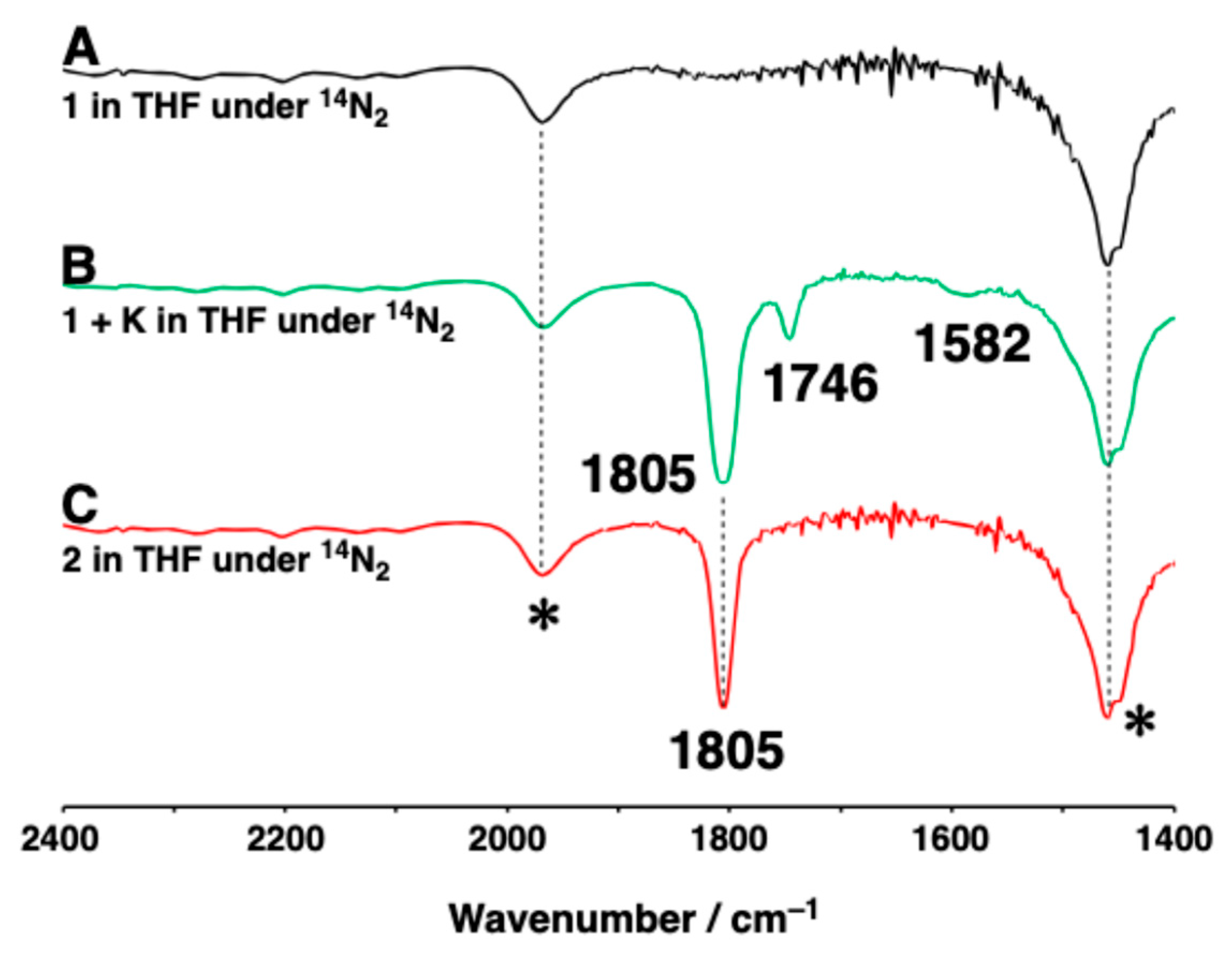
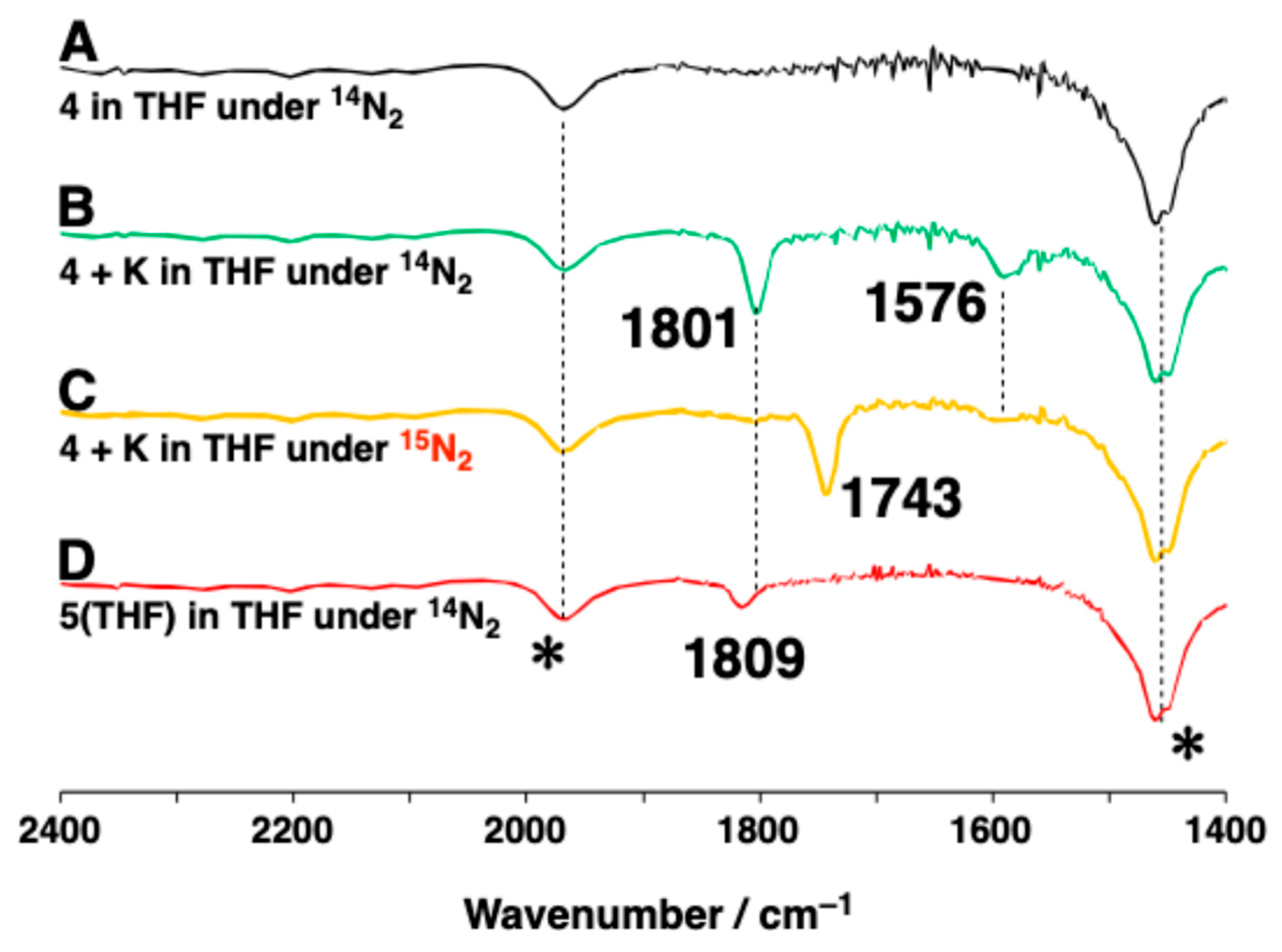
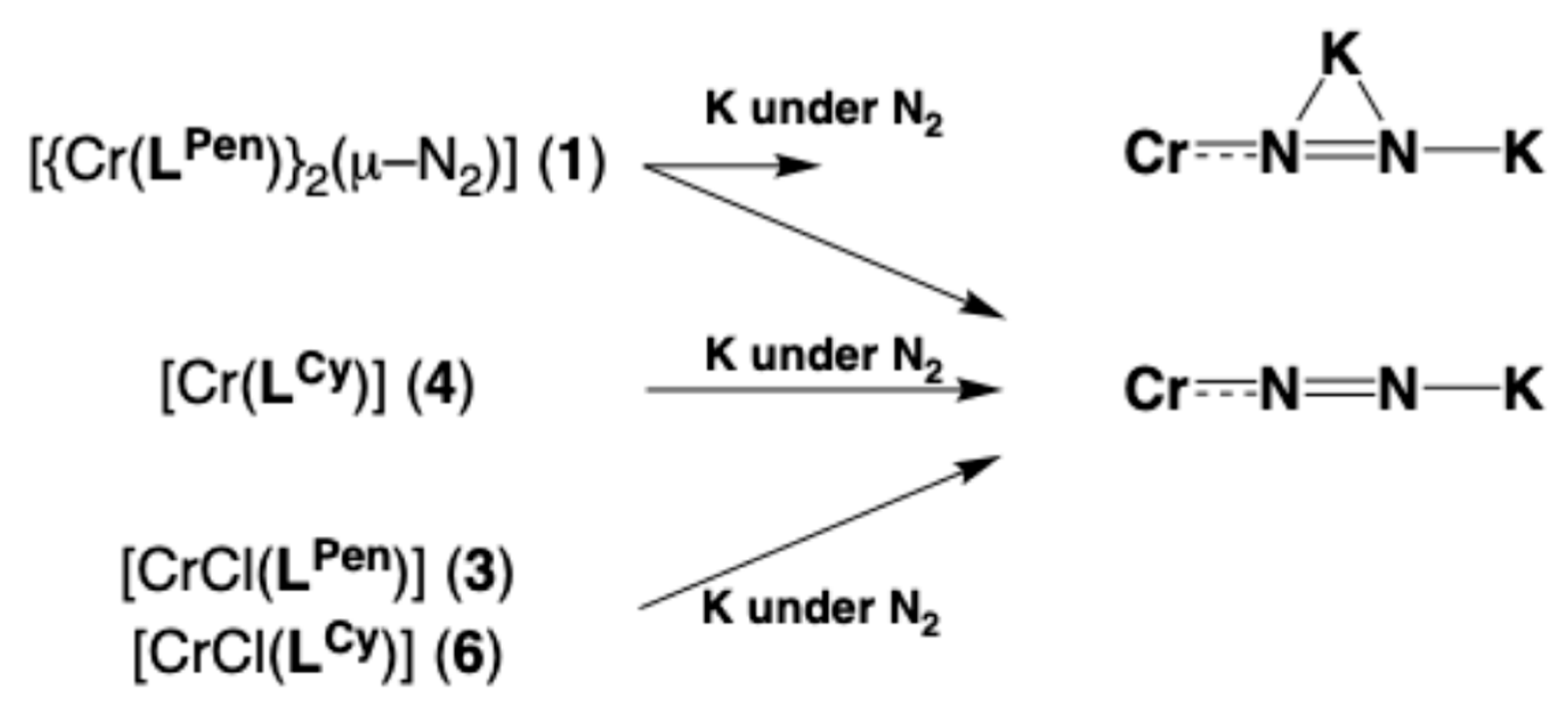
To clarify whether the above interpretations are correct, we tracked the reaction intermediates formed when 1, 3, 4, and 6 reacted with a reducing agent in THF and C6D6 solutions using IR and 1H NMR spectroscopy (Figure 15, Figure 16, Figure 17 and Figure 18 and Figures S13–S16). Note that K[C10H8] is unsuitable for IR spectroscopy in this study; therefore, K metal was used as the reducing agent. First, when complexes 1 and 4, bearing [LPen]3 and [LCy]3 ligands, respectively, were reacted with K metal under N2 atmosphere, new IR active peaks appeared at 1805, 1746, and 1582 cm−1 for complex 1 (spectrum B in Figure 15) and at 1801 and 1576 cm−1 for complex 4 (spectrum B in Figure 16), respectively. The peak at 1805 cm−1 detected in the reaction with 1 corresponded to the ν(14N–14N) stretching vibration peak (1805 cm−1) of complex 2 measured in THF (spectrum C in Figure 15). The IR peak at 1801 cm−1 detected in the reaction with complex 4 (ν(15N–15N): 1743 cm−1) was close to the peak of 5(THF) measured in THF (1809 cm−1) (spectrum D in Figure 16). The minor peak at 1746 cm−1 (spectrum B in Figure 15) detected in the reaction with complex 1 closely resembled the IR peak (1743 cm−1) (spectrum A in Figure 8) of complex 2 measured in the solid state. These findings suggest that complexes 1 and 4 react with K metal under N2 atmosphere, and that the dinitrogen ligands coordinated to the chromium ions interact with the potassium ion via a side-on and/or an end-on mode in solution, as seen in Scheme 4, similar to the crystal structures of complexes 2 and 5(THF).
Regarding the broad peaks appearing around 1582 and 1576 cm−1 after the reduction reactions of complexes 1 (Figure 15) and 4 (Figure 16), respectively, the small peaks observed at approximately the same positions in the solid-state IR spectra of complexes 2 and 5(THF), at 1576 and 1593 cm−1, respectively, did not shift even when 15N-labeled N2 was used (Figure 8 and Figure 9), suggesting that these peaks are unrelated to the dinitrogen ligand.
Furthermore, when reacting 1 or 4 with metal K, the 1H NMR peaks for complex 1, except for the Et2O peak, matched those of 2, the 1H NMR peaks for 4 could not be assigned due to its paramagnetism (Figures S13 and S14). These results indicate that complex 4, possessing sterically hindered groups, generates only compounds that the dinitrogen binds to the chromium ion and potassium ion in a bridging fashion during the reaction of the complex 4 with K metal under N2 atmosphere. On the other hand, complex 1, which possesses a low-stereochemically barrier ligand [LPen]3, appears to generate not only such compounds but also a small amount of compounds where the dinitrogen ligand bridges a chromium ion and two potassium ions in end-on and side-on modes (spectrum B in Figure 15).
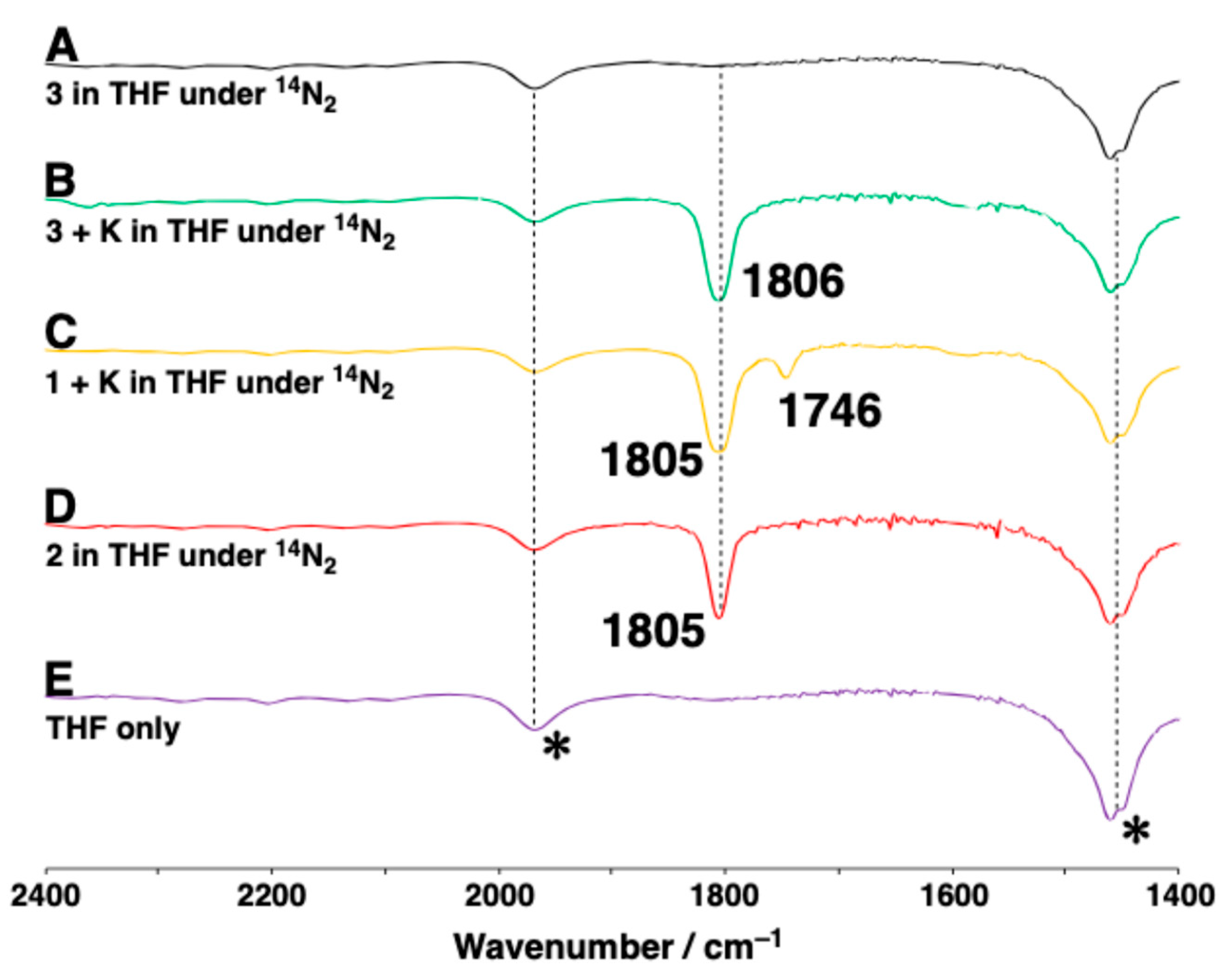
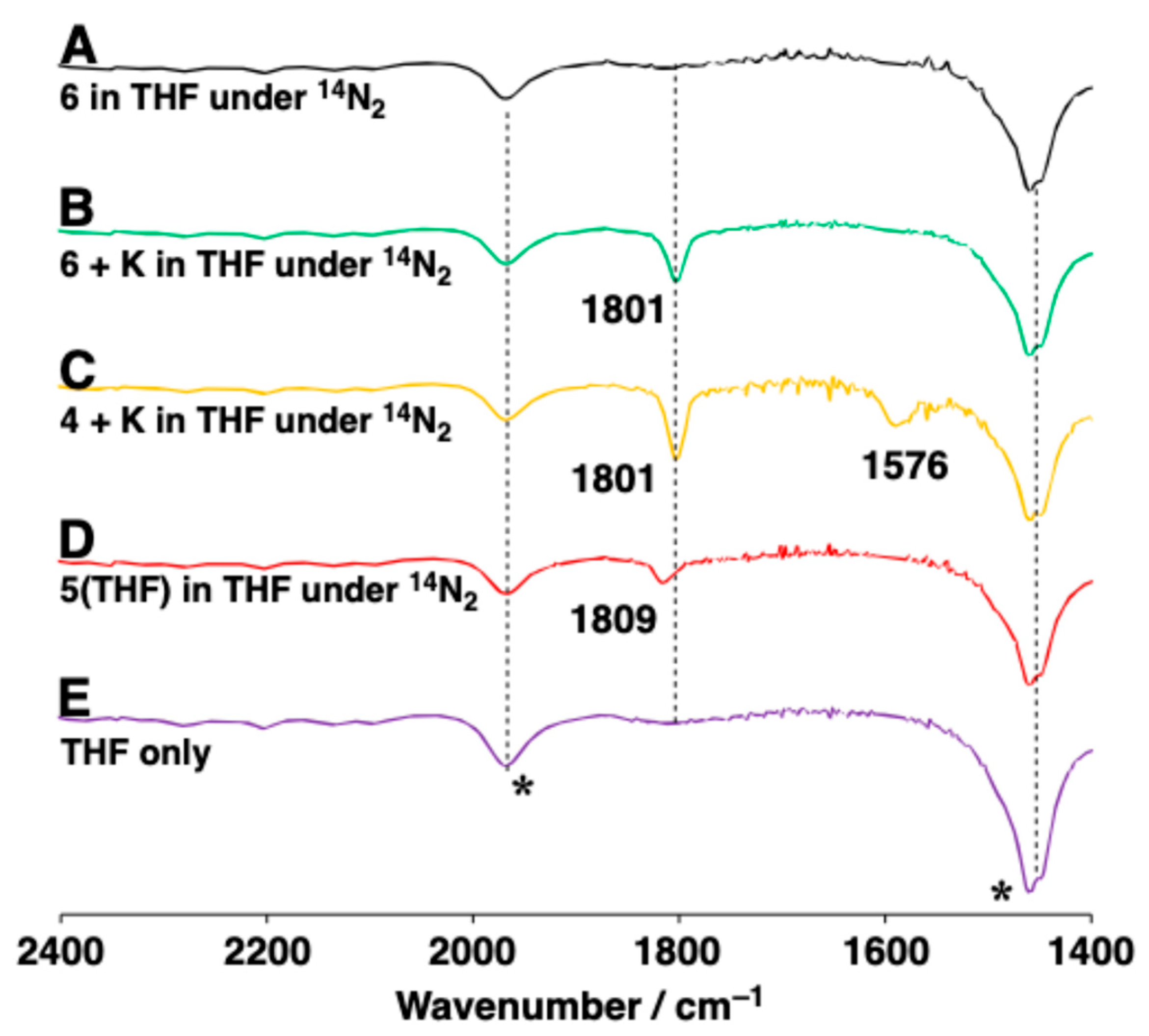
In addition, IR spectra of the solutions obtained by the reactions of Cr(IV) complexes 3 and 6 with K metal in THF under N2 atmosphere revealed new peaks at 1806 and 1801 cm−1, respectively, which are considered to originate from the ν(N–N) stretching vibrations (Figure 17 and Figure 18). The former peak at 1806 cm−1 obtained in the reaction of 3 closely matched that of complex 2 (1805 cm−1) measured in THF (spectrum D in Figure 17) and also that (1805 cm−1) obtained after reacting complex 1 with K metal in THF (spectrum C in Figure 17). The latter peak at 1801 cm−1 obtained in the reaction of 6 matched the peak of the species obtained after reacting complex 4 with K metal in THF (spectra B and C in Figure 18).
Furthermore, 1H NMR spectra of the complex solutions of 3 and 6 reacting with metallic potassium under an N2 atmosphere were investigated. The 1H NMR spectrum obtained after the reaction of 3 with K metal (Figure S15) was consistent with the spectrum of 2 in THF solution and also agreed well with the spectrum obtained after the reaction of 1 with K metal (Figure S13). The latter spectrum (Figure S16), after the reaction of 6 with K metal, resembled that of 5(THF) in C6D6 (Figure S11), although it could not be identified. Therefore, it is considered that complexes 3 and 6 also formed species similar to the structures of 2 and 5(THF), respectively, when reacted with K metal under N2 atmosphere. These behaviors are schematized as in Scheme 4. The findings regarding the formation behavior of intermediates in the reduction reaction of Cr complexes in solution well reflect the two aforementioned explanations concerning nitrogen fixation.

3. Materials and Methods

3.1. General Procedures

All manipulations were carried out under an inert atmosphere (N2 or Ar) using either a vacuum/gas manifold or an MBraun MB 150-G glovebox. Reagents and solvents employed were commercially available. All anhydrous solvents were purchased from Kanto Chemical Co., Inc. (Tokyo, Japan). The ligands, tris(2-(3-pentylamino)ethyl)amine (H3LPen) and tris(2-dicyclohexylmethylaminoethyl)amine (H3LCy2), were synthesized according to the literature methods [72]. Complex 3, [CrCl(LPen)], was synthesized according to the literature method [71].

3.2. Physical Measurements

1H and 13C NMR spectra were recorded on a JEOL JNM-ECA500 FT NMR spectrometer (JEOL Ltd., Tokyo, Japan) (500 MHz (1H), 125.77 MHz (13C)), and 15N NMR spectra were recorded on a JNM-ECA600 FT NMR spectrometer (JEOL Ltd., Tokyo, Japan) (60.815 MHz (15N)). All NMR spectra were acquired in C6D6 or DMSO-d6 at 298 K. 1H and 13C chemical shifts were referenced using residual protonated solvent resonances (C6D6: 7.16 ppm (1H) and 128.06 ppm (13C), DMSO-d6: 2.50 ppm (1H)). 15N chemical shifts were externally referenced to HCONH2 (–266.712 ppm (15N)). FT IR spectra were recorded on an Agilent Cary 630 FT IR spectrophotometer (Agilent Technologies Japan, Ltd., Tokyo, Japan). The IR spectra of the crystals were recorded using the ATR method, while those for the solution were recorded by the transmission method using a CaF2 cell. Elemental analyses were recorded on a Perkin–Elmer CHN–900 elemental analyzer (PerkinElmer Japan G.K., Kanagawa, Japan). The effective magnetic moments (μeff) of solution samples of 1, 4, and 6 were calculated from solution magnetic susceptibility data, which were determined based on the chemical shift in the methyl proton in toluene (Evans method) [75,76]. Resonance Raman spectroscopy was performed using a JASCO NRS–5500 spectrometer (JASCO, Tokyo, Japan) with a 532 nm laser as an excitation source, and the Raman shifts were calibrated using a Si plate (520 cm−1).

3.3. X-Ray Crystallography Procedures

The X-ray diffraction data for complexes 1, 2, 4, 5(THF), 5′, and 6 were collected on a Rigaku R-AXIS RAPID II diffractometer (Rigaku Holdings Corporation, Tokyo, Japan) using multi-layer mirror-monochromatized Cu (λ = 1.54178 Å) radiation. Crystallographic data and experimental details are summarized in Table S1. The calculations were performed with the Olex2 software package (version 1.5) [77]. All structures were solved by intrinsic phasing using the ShelXT program (3/2018) [78], and the remaining non-hydrogen atoms were located from subsequent difference Fourier maps. The structures were refined on F2 using full-matrix least-squares minimization with ShelXL (3/2018) [79]. All non-hydrogen atoms were refined anisotropically, unless otherwise stated. Hydrogen atoms were placed at idealized positions and refined using a riding model, unless otherwise stated. Complex 5′ was obtained from the sample vial during the 15N-NMR measurement of the sample obtained under 15N2 atmosphere. Therefore, complex 5′ contains 15N2, but it should be noted that the structural refinement in its crystal structure analysis was performed assuming these atoms to be 14N atoms (Table 4 and Table S1, Figure 14). CCDC-2502967 (1), 2502968 (2), 2218004 (3), 2502969 (4), 2502970 (5(THF)), 2504580 (5′), 2502971 (6) contain the supplementary crystallographic data for this paper. These data can be obtained free of charge via www.ccdc.cam.ac.uk/data_request/cif (accessed on 14 and 21 November 2025), or by contacting The Cambridge Crystallographic Data Centre, 12 Union Road, Cambridge CB2 1EZ, UK; fax: +44 1223 336033.

3.4. Synthesis of [{Cr(Lpen)}2(μ-14N2)] (1)

A 20 mL Schlenk flask was charged with H3LPen (1.0 g, 2.8 mmol) and Et2O (4 mL) and cooled to −60 °C under 14N2 atmosphere, to which n-butyllithium (3.2 mL, 8.4 mmol, 2.6 M in hexane) was added via syringe. After 15 min, the reaction mixture was slowly warmed to 25 °C and stirred for 1 h at room temperature. The reaction mixture was then cooled to −60 °C, and the resulting suspension was transferred via cannula to another Schlenk flask containing CrCl3 (0.44 g, 2.8 mmol). The reaction mixture was again slowly warmed to 25 °C and was stirred overnight. The solvent was removed in vacuo, and the residue was extracted with Et2O (6 mL). The extract was filtered through Celite. The Et2O extract was transferred to a 20 mL Schlenk flask and stored in a freezer at −35 °C. [{Cr(Lpen)}2(μ-14N2)] was obtained as dark red crystals, which were washed with acetone and dried in vacuo (yield 0.56 g, 48%). 1H NMR (500 MHz, C6D6, 298 K): δ (ppm) 12.14, 5.00, 0.79, −38.3. FT IR (ATR, cm−1): 2956, 2924, 2898, 2870, 2851, 2822, 2797, 1446, 1370, 1349, 1340, 1329, 1277, 1260, 1237, 1208, 1163, 1148, 1128, 1111, 1085, 1047, 1025, 1016, 997, 954, 904, 895, 861, 835, 814, 800, 755, 744, 652, 613, 598, 561, 533, 524, 477. Anal. Calcd. for C42H90Cr2N10∙1.25H2O: C, 58.53; H, 10.82; N, 16.26. Found: C, 58.51; H, 10.81; N, 16.17. μeff = 2.87 μB (Evans method).

3.5. Synthesis of [{Cr(Lpen)}2(μ-15N2)] (1′)

15N-labeled dinitrogen complex 1 (1′) was prepared following the same procedure described for complex 1, using 15N2 instead of 14N2. Complex 1′ was obtained as dark red crystals (yield 0.37 g, 31%). FT IR (ATR, cm−1): 641 (ν(Cr–15N)).

3.6. Synthesis of [{CrK(Lpen)(μ-14N2)(Et2O)}2] (2)

A 10 mL vial was charged with complex 1 (500 mg, 0.60 mmol) and Et2O (2.0 mL) under 14N2. Then, potassium metal (235 mg, 6.0 mmol, 10 equiv.) was added, and the mixture was stirred vigorously at room temperature overnight. The reaction mixture was filtered through Celite, and the filtrate was stored in the freezer at −30 °C to afford dark green crystals. The crystals were collected, washed with hexane, and dried in vacuo (yield 473 mg, 72%). This compound decomposes quickly upon exposure to air, making it impossible to measure elemental analysis. 1H NMR (500 MHz, C6D6, 298 K): δ (ppm) = 1.12 (t, 12H, CH3Et2O), 1.26 (t, 36H, CHCH2–CH3), 1.65 (t, 12H, –CH2tren), 1.87 (m, CHCH2–CH3), 1.93 (m, 12H, CHCH2–CH3), 3.27 (t, 8H, –CH2Et2O), 3.34 (t, 12H, –CH2tren), 4.31 (m, 6H, –CHCH2CH3). 13C{1H} NMR (125.77 MHz, C6D6, 298 K): δ (ppm) = 68.18, 51.93, 51.30, 29.36, 13.39. FT-IR (ATR, cm−1): 2956, 2922, 2848, 2797, 2654, 1787, 1743, 1576, 1457, 1448, 1442, 1372, 1340, 1331, 1314, 1299, 1280, 1260, 1237, 1206, 1148, 1128, 1100, 1081, 1044, 1025, 995, 947, 908, 894, 863, 829, 796, 755, 595, 559, 537, 522, 479, 444.

3.7. Synthesis of [{CrK(Lpen)(μ-15N2)(Et2O)}2] (2′)

15N-labeled dinitrogen complex 2 (2′) was prepared following the same procedure described for complex 2, using 15N2 instead of 14N2. Complex 2′ was obtained as dark green crystals (yield 427 mg, 65%). 15N NMR (60.815 MHz, C6D6, 298 K): δ (ppm) = −1.9 (Nα), −32 (Nβ). FT IR (ATR, cm−1): 1728, 1687 (ν(15N–15N)).

3.8. Synthesis of [Cr(LCy)] (4)

Complex 4 was prepared following the same procedure described for complex 1, using H3LCy instead of H3Lpen. Additionally, THF was used as the reaction solvent, and hexane was used for recrystallization, in place of Et2O (yield 301 mg, 28%). 1H NMR (500 MHz, C6D6, 298 K): δ (ppm) = 2.8, 2.6, 2.3, 2.1, 1.9, 1.8, 1.7, 1.5, 1.3, 0.9, 0.3, −18, −35, −66. FT IR (ATR, cm−1): 2954, 2919, 2874, 2848, 2796, 1603, 1528, 1446, 1377, 1347, 1325, 1305, 1280, 1258, 1234, 1208, 1144, 1131, 1096, 1072, 1031, 999, 967, 952, 891, 850, 833, 788, 781, 764, 725, 708, 691, 621, 602, 567, 485, 449. Anal. Calcd. for C45H81CrN4∙0.5(H2O): C, 73.12; H, 11.18; N, 7.58. Found: C, 73.33; H, 11.47; N, 7.51. μeff = 3.82 μB (Evans method).

3.9. Synthesis of [CrK(LCy)(μ-14N2)(18-Crown-6)(THF)] (5(THF))

A 15 mL vial was charged with complex 4 (0.20 g, 0.27 mmol) and THF (4 mL) under 14N2 atmosphere. Potassium metal (0.11 g, 2.7 mmol, 10 equiv.) was added, and the resulting mixture was stirred at R.T. overnight. The mixture solution was filtered through Celite. A solution of 18-crown-6-ether (79.3 mg, 0.30 mmol) in THF (1 mL) was added to the filtrate, and the mixture was stirred at R.T. for 1 min. Hexane (6 mL) was slowly added to the reaction mixture. The solution was allowed to stand at −35 °C and produced complex 5 as green crystals (172 mg, 51%). This compound decomposes quickly on exposure to air, making it impossible to measure elemental analysis. 1H NMR (500 MHz, C6D6, 298 K): δ (ppm) = 4.58 (br, 3H, N–CH–Cy), 3.62 (br, 6H, –CH2Cy), 3.58 (t, 4H, O–CH2THF), 3.53 (br, 12H, –CH218-crown-6-ether), 3.20 (br, 12H, –CH218-crown-6-ether), 2.38 (t, 12H, –CH2tren), 2.10–1.10 (m, 66H, –CH2Cy, –CH2n-hexane),1.42 (m, 4H, –CH2THF). FT IR (ATR, cm−1): 2911, 2844, 2745, 1824, 1465, 1444, 1364, 1349, 1334, 1327, 1284, 1256, 1249, 1236, 1219, 1193, 1178, 1141, 1131, 1113, 1105, 1068, 1040, 1016, 997, 962, 909, 891, 874, 839, 827, 800, 786, 775, 753, 727, 704, 695, 626, 615, 596, 578, 550, 533, 488, 447, 440, 432, 440, 432, 432.

3.10. Synthesis of [CrK(LCy)(μ-15N2)(18-Crown-6)(THF)] (5′(THF))

15N-labeled dinitrogen complex 5(THF) (5′(THF)) was prepared following the same procedure described for complex 5, using 15N2 instead of 14N2. Complex 5′(THF) was obtained as green crystals (yield 74.2 mg, 22%). 15N NMR (60.815 MHz, C6D6, 298 K): δ (ppm) = 8.8 (Nα), −27.5 (Nβ). FT IR (ATR, cm−1): 1757 (ν(15N–15N)).

3.11. Synthesis of [CrK(LCy)(μ-14N2)(18-Crown-6)] (5)

Complex 5 was obtained as a green, THF-free crystal by leaving a C6D6 solution of 5(THF) in a NMR sample tube at room temperature for several days (yield 10%). 1H NMR (500 MHz, C6D6, 298 K): δ (ppm) = 4.58 (br, 3H, Cy–CH–Cy), 3.62 (br, 6H, –CH2tren), 3.53 (br, 12H, –CH2Cy), 3.21 (br, 24H, –CH218-crown-6-ether), 2.39 (br, 18H, –CH2Cy), 2.10–1.10 (m, 66H, –CH2Cy, –CH2tren, –CH2n-hexane). FT IR (ATR, cm−1): 1813 (ν(14N–14N)).

3.12. Synthesis of [CrK(LCy)(μ-15N2)(18-Crown-6)] (5′)

15N-labeled dinitrogen complex 5 (5′) was obtained as a green crystal by leaving the C6D6 solution of 5′ in a NMR sample tube at room temperature for several days (yield 9.5%). 15N NMR (60.815 MHz, C6D6, 298 K): δ (ppm) = 8.8 (Nα), −27.5 (Nβ). FT IR (ATR, cm−1): 1753 (ν(15N–15N)).

3.13. Synthesis of [CrCl(LCy)] (6)

Complex 6 was synthesized by the method from the literature using [LCy]3− instead of [(Me3SiNCH2CH2)3N]3− and recrystallized from a cyclopentylmethylether solution of 6 in cyclopentylmethylether (yield 39%) [74]. 1H NMR (500 MHz, C6D6, 298 K): δ (ppm) = 13, 3.6, 3.1, 1.7, 1.5, 1.4, 1.1, −41.0. FT IR (ATR, cm−1): 2915, 2846, 2818, 1608, 1446, 1351, 1325, 1293, 1280, 1258, 1234, 1221, 1210, 1193, 1183, 1142, 1129, 1088, 1073, 1027, 1016, 967, 952, 936, 921, 893, 865, 852, 833, 800, 786, 755, 704, 626, 600, 580, 565, 546, 518, 483. Anal. Calcd. for C45H81ClCrN4∙1.25(C6H12O): C, 70.78; H, 10.86; N, 6.29. Found: C, 70.81; H, 11.13; N, 6.37. μeff = 2.96 μB (Evans method).

3.14. Reactions of 1, 2, 3, 4, 5(THF), and 6 with K[C10H8] and HOTf

A 5 mL THF solution of the reducing agent (K[C10H8]), freshly prepared from metallic potassium (5.6 mg, 0.14 mmol, 12 eq.) and naphthalene (18 mg, 0.14 mmol, 12 equiv.) in a 20 mL Schlenk flask, was added to a 5 mL THF solution of each chromium complex (5.95 × 10⁻² mmol) at −78 °C, and the mixture was stirred for 1 h under N2. HOTf (trifluoromethanesulfonic acid, 42 mg, 0.28 mmol) was added to the reaction mixture of the chromium complex under vigorous stirring, and the resultant solution was slowly warmed to 25 °C. After the solution was stirred for 1 h at room temperature, the solvents were removed under reduced pressure to give a white solid containing ammonium and hydrazinium salts. The residue in the Schlenk tube was washed with diethyl ether and then extracted with H2O (5 mL). The aqueous extract was evaporated, and the residue was analyzed using 1H NMR spectroscopy (for NH3) or the p-dimethylaminobenzaldehyde method (for N2H4).

3.15. NH3 Quantification Procedure

Ammonium salts were quantified using 1H NMR spectroscopy. The quantification of NH4+ was carried out using the method reported by Ashley and coworkers [80]. The 14NH4+ resonance was integrated using the vinyl proton of 2,5-dimethylfuran in DMSO-d6 sealed in the capillary as the reference (d: 5.83, s, 2H). This quantification was calibrated using a standard 2.6 × 10⁻² M solution of NH4+ in DMSO-d6 (Figure S17 and Table S3).

3.16. N2H4 Quantification Procedure

The quantification of N2H62+ was carried out using the method reported by Ashley and coworkers [80]. The residues were dissolved in H2O (10 mL), and the resulting solution was diluted tenfold with H2O. Aliquots of the diluted solution were analyzed for N2H4 via UV-vis spectroscopy using a standard spectrophotometric method. This involved reacting the sample with an acidic p-dimethylaminobenzaldehyde solution and generating a yellow azine dye with a characteristic absorption maximum (λmax) at 458 nm. The N2H4 content in the aliquot was quantified by comparison to the calibration curve (Figure S18).

4. Conclusions

In this study, six chromium complexes with the triamidoamine derivative ligand bearing bulky substituents at their terminal positions, [LPen]3− or [LCy]3−, were synthesized and structurally characterized. Using these chromium complexes, the effect of the ligand substituents on the nitrogen fixation reactivity was investigated. When employing a chromium complex bearing a slightly less bulky ligand [LPen]3−, the dinitrogen dichromium complex Cr(IV)-N2-Cr(IV) (1) was prepared under a N2 atmosphere. A further reduction of this complex with a reductant K metal under a N2 atmosphere yielded the dinitrogen tetranuclear Cr2K2 complex Cr(K)-(μ-N2)2-KCr (2). On the other hand, when chromium complexes bearing more bulky ligands [LCy]3− were employed, the steric hindrance prevented the formation of dichromium dinitrogen complexes, unlike those obtained with chromium complexes bearing the [LPen]3− ligand. Instead, an axially vacant Cr(III) complex 4 was obtained. However, interestingly, when complex 4 was reduced with K metal in the presence of 18-crown-6 ether under a N2 atmosphere, a dinuclear Cr(IV)-N2-K(18-crown-6 ether)(THF) complex (5(THF)) was obtained. This formation is attributable to the sterically smaller ligand of the 18-crown 6-ether. The formation of dinitrogen chromium complexes 1, 2, and 5(THF) was also confirmed by Raman and IR spectroscopy. Cr(IV)Cl complexes 3 and 6, possessing [LPen]3− and [LCy]3−, respectively, and lacking N2, were also synthesized and structurally characterized to study their nitrogen fixation reactivity.
For chromium complexes 2 and 5(THF) with 15N-labeled N2 (2′ and 5′(THF)), 15N NMR and solution IR spectroscopic measurements were performed, revealing that the potassium ions, which coordinated in both side-on and end-on modes, as seen in the crystal of 2, gradually transitioned to coordinate exclusively in the end-on mode in solution. Furthermore, the results obtained from the 15N NMR spectrum of 5′(THF) revealed that the THF ligand was removed from complex 5(THF) in solution, leading to the formation of complex 5. Using single crystals accidentally obtained from the NMR sample tube, X-ray structural analysis was performed to yield complex 5 without THF, confirming its structure as predicted in solution.
When complexes 1 and 3 bearing the [LPen]3− ligand reacted with potassium in solution under a N2 atmosphere, substances exhibiting IR and 1H NMR spectra similar to those of complex 2 were obtained. Furthermore, the spectra obtained when complexes 4 and 6, bearing the [LCy]3− ligand, reacted with metallic K under a N2 atmosphere were also similar to those of 5(THF).
Finally, nitrogen fixation reactivity was studied using complexes 1, 2, 3, 4, 5(THF), and 6 under N2, employing K[C10H8] as a reductant and HOTf as a proton source. The results showed that hydrazine and small amounts of ammonia were obtained in all cases. However, compared to the nitrogen fixation reaction previously reported using Cr complexes with a [LBn]3− ligand [71], the ammonia yield decreased in all cases. And the Cr complexes 4 and 5, which possessed the bulky ligand [LCy]3−, generated significantly more hydrazine than the others. These results are likely due to the fact that while the [LPen]3− and [LCy]3− ligands used in this study possess tertiary carbons, [LBn]3− has a secondary carbon. This is thought to arise from the steric hindrance of the [LPen]3− and [LCy]3− ligands inhibiting the supply of K+ and protons. The findings obtained in this study indicate that when Cr complexes of triamidoamine ligands bearing bulky substituents react with N2 in the presence of K, the resulting dinitrogen chromium complexes are influenced by K bound via ligand-dependent interaction modes. The results obtained here will provide important insights into dinitrogen activation and nitrogen fixation using chromium complexes, which have been scarcely reported to date.

Supplementary Materials

The following supporting information can be downloaded at https://www.mdpi.com/article/10.3390/inorganics14010024/s1, Table S1: Experimental data for X-ray diffraction studies on crystalline complexes 1, 2, 4, 5(THF), 5′, and 6; Table S2: Selected bond lengths (Å) and angles (deg) of 4; Figure S1: Raman spectra of 1 and 15N labeled 1 (1′) in toluene (λex = 532 nm) at room temperature; Figure S2: IR spectra of 2 in toluene, solvent toluene, and the difference; Figure S3: IR spectra of 5(THF) in toluene, solvent toluene, and the difference; Figure S4: 15N NMR spectra of 15N labeled-dinitrogen complex 2 (2′) after 10,000, 20,000, 30,000, 40,000, and 50,000 scans in C6D6 (60.815 MHz); Figure S5: IR spectra of 5 and 15N labeled-dinitrogen complex 5 (5′) (ATR); Figure S6: 1H NMR spectra of 5 in C6D6 (500 MHz); Figure S7: 1H NMR spectrum of 1 in C6D6 (500 MHz); Figure S8: 1H NMR spectra of 2 in C6D6 (500 MHz); Figure S9: 1H NMR spectra of 3 in C6D6 (500 MHz); Figure S10: 1H NMR spectra of 4 in C6D6 (500 MHz); Figure S11: 1H NMR spectra of 5(THF) in C6D6 (500 MHz); Figure S12: 1H NMR spectra of 6 in C6D6 (500 MHz); Figure S13: 1H NMR spectra of 2 in C6D6 and 1 reacted with K metal in C6D6 under N2 (500 MHz); Figure S14: 1H NMR spectra of 4 reacted with K metal under N2 in C6D6 (500 MHz); Figure S15: 1H NMR spectra of 2 in C6D6 and 3 reacted with K metal in C6D6 under 14N2; Figure S16: 1H NMR spectra of 6 reacted with K metal in C6D6 under 14N2; Table S3: yields of NH3 and N2H4 from the reaction of complexes 1, 2, 3, 4, 5(THF), and 6 with K[C10H8] and an HOTf; Figure S17: 1H NMR spectrum of 14NH4+ that was obtained from the reaction of 1 with 12 equiv. K[C10H8] and 12 equiv. HOTf under 14N2 (DMSO-d6, 500 MHz); Figure S18: Calibration curves for hydrazine quantification.

Author Contributions

Conceptualization, T.K., Y.K. (Yoshiaki Kokub), and Y.K. (Yuji Kajita); methodology, T.K., Y.K. (Yoshiaki Kokub), and Y.K. (Yuji Kajita); validation, T.K., Y.K. (Yoshiaki Kokub), and Y.K. (Yuji Kajita); formal analysis, T.K., Y.K. (Yoshiaki Kokub), Y.K. (Yuji Kajita), H.N., T.F., and T.O.; investigation, T.K., Y.K. (Yoshiaki Kokub), and Y.K. (Yuji Kajita); data curation, T.K. and Y.K. (Yoshiaki Kokub); writing—original draft preparation, T.K., Y.K. (Yoshiaki Kokub), and Y.K. (Yuji Kajita); writing—review and editing, Y.K. (Yuji Kajita) and H.M.; supervision, Y.K. (Yuji Kajita) and H.M.; project administration, Y.K. (Yuji Kajita); funding acquisition, Y.K. (Yoshiaki Kokub), Y.K. (Yuji Kajita), and H.M. All authors have read and agreed to the published version of the manuscript.

Funding

This research was funded by the Japan Society for the Promotion of Science (JSPS), grant number 24K217860, and the Nitto Foundation.

Institutional Review Board Statement

Not applicable.

Informed Consent Statement

Not applicable.

Data Availability Statement

The original contributions presented in this study are included in the article/Supplementary Material. Further inquiries can be directed to the corresponding author(s).

Acknowledgments

We thank Haruyo Nagao (Institute for Molecular Science) for the 15N NMR spectroscopy measurement. This work was conducted in the Institute for Molecular Science, supported by the Advanced Research Infrastructure for Materials and Nanotechnology in Japan (ARIM) of the Ministry of Education, Culture, Sports, Science and Technology (MEXT). Proposal Number JPMXP1225MS1082. We also acknowledge the Japan Society for the Promotion of Science (JSPS) for a Grant-in Aid for Challenging Research Exploratory Research (24K21786) and the Nitto Foundation.

Conflicts of Interest

The authors declare no conflicts of interest.

Abbreviations

The following abbreviations are used in this manuscript:
THFTetrahydrofuran
HOTfTrifluoromethanesulfonic Acid
IRInfrared
trenTris (2-aminoethyl) amine
n-BuLin-Butyllithium
Et2ODiethylether
ORTEPOak Ridge Thermal-Ellipsoid Plot
NMRNuclear Magnetic Resonance

References

  1. Schlögl, R. Catalytic Synthesis of Ammonia—A “Never-Ending Story”? Angew. Chem. Int. Ed. 2003, 42, 2004–2008. [Google Scholar] [CrossRef]
  2. Zhang, X.; Ward, B.B.; Sigman, D.M. Global Nitrogen Cycle: Critical Enzymes, Organisms, and Processes for Nitrogen Budgets and Dynamics. Chem. Rev. 2020, 120, 5308–5351. [Google Scholar] [CrossRef]
  3. Elishav, O.; Lis, B.M.; Miller, E.M.; Arent, D.J.; Valera-Medina, A.; Dana, A.G.; Shter, G.E.; Grader, G.S. Progress and Prospective of Nitrogen-Based Alternative Fuels. Chem. Rev. 2020, 120, 5352–5436. [Google Scholar] [CrossRef]
  4. Yandulov, D.V.; Schrock, R.R. Catalytic Reduction of Dinitrogen to Ammonia at a Single Molybdenum Center. Science 2003, 301, 76–78. [Google Scholar] [CrossRef]
  5. Schrock, R.R. Catalytic Reduction of Dinitrogen to Ammonia at a Single Molybdenum Center. Acc. Chem. Res. 2005, 38, 955–962. [Google Scholar] [CrossRef]
  6. Schrock, R.R. Catalytic Reduction of Dinitrogen to Ammonia by Molybdenum: Theory versus Experiment. Angew. Chem. Int. Ed. 2008, 47, 5512–5522. [Google Scholar] [CrossRef] [PubMed]
  7. Mitsumoto, T.; Ashida, Y.; Arashiba, K.; Kuriyama, S.; Egi, A.; Tanaka, H.; Yoshizawa, K.; Nishibayashi, Y. Catalytic Activity of Molybdenum Complexes Bearing PNP-Type Pincer Ligand toward Ammonia Formation. Angew. Chem. Int. Ed. 2023, 62, e202306631. [Google Scholar]
  8. Tanabe, Y.; Nishibayashi, Y. Catalytic Nitrogen Fixation Using Well-Defined Molecular Catalysts under Ambient or Mild Reaction Conditions. Angew. Chem. Int. Ed. 2024, 63, e202406404. [Google Scholar] [CrossRef]
  9. Mitsumoto, T.; Nakamura, T.; Tanaka, H.; Yoshizawa, K.; Nishibayashi, Y. Cooperative Ammonia Formation Catalyzed by Molybdenum and Samarium Complexes. Angew. Chem. Int. Ed. 2025, 64, e202507061. [Google Scholar] [CrossRef] [PubMed]
  10. Mitsumoto, T.; Nishibayashi, Y. Molybdenum-Catalyzed Ammonia Synthesis by Using Zero-Valent Metal Powder with Alcohols or Water. Angew. Chem. Int. Ed. 2025, 64, e202423858. [Google Scholar] [CrossRef] [PubMed]
  11. McWilliams, S.F.; Holland, P.L. Dinitrogen Binding and Cleavage by Multinuclear Iron Complexes. Acc. Chem. Res. 2015, 48, 2059–2065. [Google Scholar] [CrossRef]
  12. Tanaka, H.; Nishibayashi, Y.; Yoshizawa, K. Interplay between Theory and Experiment for Ammonia Synthesis Catalyzed by Transition Metal Complexes. Acc. Chem. Res. 2016, 49, 987–995. [Google Scholar] [CrossRef]
  13. Ashida, Y.; Nishibayashi, Y. Catalytic Conversion of Nitrogen Molecule into Ammonia Using Molybdenum Complexes under Ambient Reaction Conditions. Chem. Commun. 2021, 57, 1176–1189. [Google Scholar] [CrossRef]
  14. Tanabe, Y.; Nishibayashi, Y. Comprehensive insights into synthetic nitrogen fixation assisted by molecular catalysts under ambient or mild conditions. Chem. Soc. Rev. 2021, 50, 5201–5242. [Google Scholar] [CrossRef]
  15. Tanabe, Y.; Nishibayashi, Y. Recent advances in catalytic silylation of dinitrogen using transition metal complexes. Coord. Chem. Rev. 2019, 389, 73–93. [Google Scholar] [CrossRef]
  16. Tanabe, Y.; Nishibayashi, Y. Recent advances in catalytic nitrogen fixation using transition metal-dinitrogen complexes under mild reaction conditions. Coord. Chem. Rev. 2022, 472, 214783. [Google Scholar] [CrossRef]
  17. Tanifuji, K.; Ohki, Y. Metal-Sulfur Compounds in N2 Reduction and Nitrogenase-Related Chemistry. Chem. Rev. 2020, 120, 5194–5251. [Google Scholar] [CrossRef]
  18. Singh, D.; Buratto, W.R.; Torres, J.F.; Murray, L.J. Activation of Dinitrogen by Polynuclear Metal Complexes. Chem. Rev. 2020, 120, 5517–5581. [Google Scholar] [CrossRef] [PubMed]
  19. Chalkley, M.J.; Drover, M.W.; Peters, J.C. Catalytic N2-to-NH3 (or-N2H4) Conversion by Well-Defined Molecular Coordination Complexes. Chem. Rev. 2020, 120, 5582–5636. [Google Scholar] [CrossRef]
  20. Kim, S.; Loose, F.; Chirik, P.J. Beyond Ammonia: Nitrogen -Element Bond Forming Reactions with Coordinated Dinitrogen. Chem. Rev. 2020, 120, 5637–5681. [Google Scholar] [CrossRef] [PubMed]
  21. Khoenkhoen, N.; de Bruin, B.; Reek, J.N.H.; Dzik, W.I. Reactivity of Dinitrogen Bound to Mid-and Late-Transition-Metal Centers. Eur. J. Inorg. Chem. 2015, 2015, 567–598. [Google Scholar] [CrossRef]
  22. Stucke, N.; Flöser, B.M.; Weyrich, T.; Tuczek, F. Catalytic Ammonia Synthesis with Transition Metal Complexes: Recent Developments. Eur. J. Inorg. Chem. 2018, 2018, 1337–1355. [Google Scholar] [CrossRef]
  23. Bhutto, S.M.; Holland, P.L. Dinitrogen Activation and Functionalization Using β-Diketiminate Iron Complexes. Eur. J. Inorg. Chem. 2019, 2019, 1861–1869. [Google Scholar] [CrossRef]
  24. Kendall, A.J.; Mock, M.T. Dinitrogen Activation and Functionalization with Chromium. Eur. J. Inorg. Chem. 2020, 2020, 1358–1375. [Google Scholar] [CrossRef]
  25. Nishibayashi, Y. Recent Progress in Transition-Metal-Catalyzed Reduction of Molecular Dinitrogen under Ambient Reaction Conditions. Inorg. Chem. 2015, 54, 9234–9247. [Google Scholar] [CrossRef]
  26. Foster, S.L.; Perez Bakovic, S.I.; Duda, R.D.; Maheshwari, S.; Milton, R.D.; Minteer, S.D.; Janik, M.J.; Renner, J.N.; Greenlee, L.F. Catalysts for nitrogen reduction to ammonia. Nat. Catal. 2018, 1, 490–500. [Google Scholar] [CrossRef]
  27. Burford, R.J.; Fryzuk, M.D. Examining the relationship between coordination mode and reactivity of dinitrogen. Nat. Rev. Chem. 2017, 1, 0026. [Google Scholar] [CrossRef]
  28. Kuriyama, S.; Nishibayashi, Y. Development of catalytic nitrogen fixation using transition metal complexes not relevant to nitrogenases. Tetrahedron 2021, 83, 131986. [Google Scholar] [CrossRef]
  29. Kireev, N.V.; Filippov, O.A.; Epstein, L.M.; Shubina, E.S.; Belkova, N.V. Activation of dinitrogen by group 6 metal complexes. Russ. Chem. Bull. 2023, 72, 83–102. [Google Scholar] [CrossRef]
  30. Itabashi, T.; Arashiba, K.; Egi, A.; Tanaka, H.; Sugiyama, K.; Suginome, S.; Kuriyama, S.; Yoshizawa, K.; Nishibayashi, Y. Direct synthesis of cyanate anion from dinitrogen catalysed by molybdenum complexes bearing pincer-type ligand. Nat. Commun. 2022, 13, 6161. [Google Scholar] [CrossRef]
  31. Ashida, Y.; Onozuka, Y.; Arashiba, K.; Konomi, A.; Tanaka, H.; Kuriyama, S.; Yamazaki, Y.; Yoshizawa, K.; Nishibayashi, Y. Catalytic nitrogen fixation using visible light energy. Nat. Commun. 2022, 13, 7263. [Google Scholar] [CrossRef]
  32. Yamazaki, Y.; Endo, Y.; Nishibayashi, Y. Catalytic ammonia formation from dinitrogen, water, and visible light energy. Nat. Commun. 2025, 16, 4540. [Google Scholar] [CrossRef]
  33. Ashida, Y.; Mizushima, T.; Arashiba, K.; Egi, A.; Tanaka, H.; Yoshizawa, K.; Nishibayashi, Y. Catalytic production of ammonia from dinitrogen employing molybdenum complexes bearing N-heterocyclic carbene-based PCP-type pincer ligands. Nat. Synth. 2023, 2, 635–644. [Google Scholar] [CrossRef]
  34. Suginome, S.; Murota, K.; Yamamoto, A.; Yoshida, H.; Nishibayashi, Y. Mechanochemical nitrogen fixation catalysed by molybdenum complexes. Nat. Synth. 2025, 4, 243–251. [Google Scholar] [CrossRef]
  35. Suginome, S.; Nishibayashi, Y. Direct Synthesis of Organonitrogen Compounds from Dinitrogen Using Transition Metal Complexes: Leap from Stoichiometric Reactions to Catalytic Reactions. ChemCatChem 2023, 15, e202300850. [Google Scholar] [CrossRef]
  36. Eizawa, A.; Arashiba, K.; Tanaka, H.; Konomi, A.; Yoshizawa, K.; Nishibayashi, Y. Design, synthesis and reactivity of dimolybdenum complex bearing quaterphenylene-bridged pyridine-based PNP-type pincer ligand. Dalton Trans. 2023, 52, 14012–14016. [Google Scholar] [CrossRef]
  37. Feng, D.; Zhou, L.; Liu, C.; Li, H.; Zhang, Y.; Yao, Y.; Ma, T. Enhanced electrochemical reduction of N2 to NH3 by interfacial engineering of biomass-derived Fe, Mo-bimetallic composite. Electrochim. Acta 2024, 484, 144096. [Google Scholar]
  38. Escomel, L.; Martins, F.F.; Vendier, L.; Coffinet, A.; Queyriaux, N.; Krewald, V.; Simonneau, A. Coordination of Al(C6F5)3 vs. B(C6F5)3 on group 6 end-on dinitrogen complexes: Chemical and structural divergences. Chem. Sci. 2024, 15, 11321–11336. [Google Scholar]
  39. Zhang, G.; Li, Q.; Wang, X.; Jin, L.; Liao, Q. Diverse Behaviors of N2 on Mo Centers Bearing POCOP-Pincer Ligands and the Role of π-Electron Configuration in Regulating the Pathway of N2 Activation. J. Am. Chem. Soc. 2025, 147, 3747–3757. [Google Scholar]
  40. Suginome, S.; Okochi, A.; Nakamura, T.; Konomi, A.; Tanaka, H.; Yoshizawa, K.; Nishibayashi, Y. Catalytic Reduction of Dinitrogen via Hydroboration. J. Am. Chem. Soc. 2025, 147, 26684–26692. [Google Scholar] [CrossRef] [PubMed]
  41. Yamazaki, Y.; Nakaya, K.; Nishibayashi, Y. Synthesis of Molybdenum Complexes Bearing Pyridine-Based PNP-Type Pincer Ligands with Pendent Pyridyl Unit and Their Catalytic Activity for Ammonia Formation. Organometallics 2024, 43, 2747–2754. [Google Scholar] [CrossRef]
  42. Mock, M.T.; Chen, S.; Rousseau, R.; O’Hagan, M.J.; Dougherty, W.G.; Scott Kassel, W.; DuBois, D.L.; Bullock, R.M. A rare terminal dinitrogen complex of chromium. Chem. Commun. 2011, 47, 12212–12214. [Google Scholar] [CrossRef]
  43. Akturk, E.A.; Yap, G.P.A.; Theopold, K.H. Mechanism-based designed of labile precursors for chromium(I) chemistry. Chem. Commun. 2015, 51, 15402–15405. [Google Scholar] [CrossRef] [PubMed]
  44. Egbert, J.D.; O’Hagan, M.; Wiedner, E.S.; Morris Bullock, R.; Piro, N.A.; Scott Kassel, W.; Mock, M.T. Putting chromium on the map for N2 reduction: Production of hydrazine and ammonia. A study of cis-M(N2)2 (M = Cr, Mo, W) bis (diphosphine) complexes. Chem. Commun. 2016, 52, 9343–9346. [Google Scholar] [CrossRef] [PubMed]
  45. Li, J.; Yin, J.; Wang, G.-X.; Yin, Z.-B.; Zhang, W.-X.; Xi, Z. Synthesis and reactivity of asymmetric Cr(I) dinitrogen complexes supported by cyclopentadienyl-phosphine ligands. Chem. Commun. 2019, 55, 9641–9644. [Google Scholar] [CrossRef]
  46. Duletski, O.L.; Platz, D.; Pollock, C.J.; Mosquera, M.A.; Arulsamy, N.; Mock, M.T. Dinitrogen activation at chromium by photochemically induced CrII-C bond homolysis. Chem. Commun. 2024, 60, 7029–7032. [Google Scholar] [CrossRef] [PubMed]
  47. Ashida, Y.; Egi, A.; Arashiba, K.; Tanaka, H.; Mitsumoto, T.; Kuriyama, S.; Yoshizawa, K.; Nishibayashi, Y. Catalytic Reduction of Dinitrogen into Ammonia and Hydrazine Using Chromium Complexes Bearing PCP-Pincer Ligand. Chem. Eur. J. 2022, 28, e202200557. [Google Scholar]
  48. Eaton, M.C.; Knight, B.J.; Catalano, V.J.; Murray, L.J. Evaluating Metal Ion Identity on Catalytic Silylation of Dinitrogen Using a Series of Trimetallic Complexes. Eur. J. Inorg. Chem. 2020, 2020, 1519–1524. [Google Scholar] [CrossRef]
  49. Vidyaratne, I.; Scott, J.; Gambarotta, S.; Budzelaar, P.H.M. Dinitrogen Activation, Partial Reduction, and Formation of Coordinated Imide Promoted by a Chromium Diiminepyridine Complex. Inorg. Chem. 2007, 46, 7040–7049. [Google Scholar] [CrossRef]
  50. Berben, L.A.; Kozimor, S.A. Dinitrogen and Acetylide Complexes of Low-Valent Chromium. Inorg. Chem. 2008, 47, 4639–4647. [Google Scholar] [CrossRef]
  51. Hoffert, W.A.; Rappé, A.K.; Shores, M.P. Unusual Electronic Effects Imparted by Bridging Dinitrogen: Experimental and Theoretical Investigation. Inorg. Chem. 2010, 49, 9497–9507. [Google Scholar] [CrossRef] [PubMed]
  52. Mock, M.T.; Pierpont, A.W.; Egbert, J.D.; O’Hagan, M.; Chen, S.; Morris Bullock, R.; Dougherty, W.G.; Scott Kassel, W.; Rousseau, R. Protonation Studies of a Mono-Dinitrogen Complex of Chromium Supported by a 12-Membered Phosphorus Macrocycle Containing Pendant Amines. Inorg. Chem. 2015, 54, 4827–4839. [Google Scholar] [CrossRef]
  53. Salt, J.E.; Girolami, G.S.; Wilkinson, G.; Motevalli, M.; Thornton-Pett, M.; Hursthouse, M.B. Synthesis and Characterisation of 1,2-Bis(dimethylphosphino)ethane (dmpe) Complexes of Chromium-(0) and -(IV): X-Ray Crystal Structures of trans-Cr(N2)2(dmpe)2, cis-Cr(CO)2(dmpe)2, Cr(C2Ph2)2(dmpe), and CrH4(dmpe)2. J. Chem. Soc. Dalton Trans. 1985, 1985, 685–692. [Google Scholar]
  54. Denholm, S.; Hunter, G.; Weakley, T.J.R. Dinitrogen Complexes derived from Tricarbonyl(η6-hexaethylbenzene)chromium(0): Crystal and Molecular Structure of μ-dinitrogen-bis[dicarbonyl(η6-hexaethylbenzene)chromium(0)]-Toluene (1/1). J. Chem. Soc. Dalton Trans. 1987, 1987, 2789–2791. [Google Scholar]
  55. Sobota, P.; Jeżowska-Trzebiatowska, B. Fixation of Dinitrogen and Acetylene by the System CrCl2-Mg. Isolation and Properties of Chromium Complexes with Fixed N2 and C2H2. J. Organomet. Chem. 1977, 131, 341–345. [Google Scholar]
  56. Wang, G.-X.; Yin, Z.-B.; Wei, J.; Xi, Z. Dinitrogen Activation and Functionalization Affording Chromium Diazenido and Hydrazido Complexes. Acc. Chem. Res. 2023, 56, 3211–3222. [Google Scholar] [CrossRef]
  57. Monillas, W.H.; Yap, G.P.A.; MacAdams, L.A.; Theopold, K.H. Binding and Activation of Small Molecules by Three-Coordinate Cr(I). J. Am. Chem. Soc. 2007, 129, 8090–8091. [Google Scholar] [CrossRef]
  58. Mock, M.T.; Chen, S.; O’Hagan, M.; Rousseau, R.; Dougherty, W.G.; Scott Kassel, W.; Morris Bullock, R. Dinitrogen Reduction by a Chromium(0) Complex Supported by a 16-Membered Phosphorus Macrocycle. J. Am. Chem. Soc. 2013, 135, 11493–11496. [Google Scholar] [CrossRef] [PubMed]
  59. Kendall, A.J.; Johnson, S.I.; Morris Bullock, R.; Mock, M.T. Catalytic Silylation of N2 and Synthesis of NH3 and N2H4 by Net Hydrogen Atom Transfer Reactions Using a Chromium P4 Macrocycle. J. Am. Chem. Soc. 2018, 140, 2528–2536. [Google Scholar] [CrossRef] [PubMed]
  60. Yin, J.; Li, J.; Wang, G.-X.; Yin, Z.-B.; Zhang, W.-X.; Xi, Z. Dinitrogen Functionalization Affording Chromium hydrazido Complex. J. Am. Chem. Soc. 2019, 141, 4241–4247. [Google Scholar] [CrossRef]
  61. Yin, Z.-B.; Wu, B.; Wang, G.-X.; Wei, J.; Xi, Z. Dinitrogen Functionalization Affording Chromium Diazenido and Side-on η2-Hydrazido Complexes. J. Am. Chem. Soc. 2023, 145, 7065–7070. [Google Scholar]
  62. Wang, G.-X.; Wang, X.; Jiang, Y.; Chen, W.; Shan, C.; Zhang, P.; Wei, J.; Ye, S.; Xi, Z. Snapshots of Early-Stage Quantitative N2 Electrophilic Functionalization. J. Am. Chem. Soc. 2023, 145, 9746–9754. [Google Scholar] [CrossRef] [PubMed]
  63. Wu, B.; Chen, W.; Yan, H.; Zhang, X.; Wei, J.; Xi, Z.; Wang, G.-X.; Ye, S. Trisilylation of a Formal Cr(-I) Bis-dinitrogen Complex. J. Am. Chem. Soc. 2025, 147, 32480–32493. [Google Scholar]
  64. Wang, X.; Wu, Y.; Wang, Y.; Sun, R.; Wei, J.; Xi, Z. Harnessing Chromium(V) Hydrazido Intermediates for N2 Functionalization to Multisubstituted Hydrazines through Ligand Migration. J. Am. Chem. Soc. 2025, 147, 35413–35421. [Google Scholar] [CrossRef]
  65. Wang, X.; Wang, Y.; Wu, Y.; Wang, G.-X.; Wei, J.; Xi, Z. Syntheses and Characterizations of Hetero-Bimetallic Chromium-Dinitrogen Transition-Metal Complexes. Inorg. Chem. 2023, 62, 18641–18648. [Google Scholar] [CrossRef]
  66. Hao, M.-T.; Zhang, B.; Li, D.; Wujieti, B.; Li, X.; Chen, B.-Z. Theoretical Studies on the Reduction of N2 to NH3/N2H4 Catalyzed by Chromium Complexes. Inorg. Chem. 2025, 64, 7311–7324. [Google Scholar] [CrossRef]
  67. Li, Z.; Liu, X.-X.; Wang, X.; Peng, L.-Y.; Liu, C.; Yuan, Z.; Liu, Y.; Cui, G.; Hu, S. Catalytic Silylation of Dinitrogen by PCP-Ligated Chromium Complexes. ACS Catal. 2025, 15, 13337–13345. [Google Scholar] [CrossRef]
  68. Yin, Z.-B.; Wang, G.-X.; Yan, X.; Wei, J.; Xi, Z. Construction of N-E bonds via Lewis acid-promoted functionalization of chromium-dinitrogen complexes. Nat. Commun. 2025, 16, 674. [Google Scholar]
  69. Darani, F.A.; Yap, G.P.A.; Theopold, K.H. The Intrinsic Barrier for N≡N Bond Cleavage or Formation Mediated by the Cp*Cr(dmpe) Fragment Is Insurmountable. Organometallics 2023, 42, 1324–1330. [Google Scholar] [CrossRef]
  70. Uchida, K.; Kitayama, T.; Tanaka, S.; Adachi, S.; Iguchi, H.; Sakamoto, R.; Takaishi, S. High-Pressure Synthesis and Post-synthetic Elimination of N2 Molecule of the Chromium Dinitrogen Complex, [Cr(PCy3)2(CO)3(N2)]. Organometallics 2025, 44, 459–463. [Google Scholar] [CrossRef]
  71. Kokubo, Y.; Tsuzuki, K.; Sugiura, H.; Yomura, S.; Wasada-Tsutsui, Y.; Ozawa, T.; Yanagisawa, S.; Kubo, M.; Takeyama, T.; Yamaguchi, T.; et al. Syntheses, Characterizations, Crystal Structures, and Protonation Reactions of Dinitrogen Chromium Complexes Supported with Triamidoamine Ligands. Inorg. Chem. 2023, 62, 5320–5333. [Google Scholar] [CrossRef]
  72. Kokubo, Y.; Igarashi, I.; Nakao, K.; Hachiya, W.; Kugimiya, S.; Ozawa, T.; Masuda, H.; Kajita, Y. The Steric Effect in Preparations of Vanadium(II)/(III) Dinitrogen Complexes of Triamidoamine Ligands Bearing Bulky Substituents. Molecules 2022, 27, 5864. [Google Scholar]
  73. Haynes, W.M.; Lide, D.R.; Bruno, T.J. CRC Handbook of Chemistry and Physics, 97th ed.; CRC Press: Boca Raton, FL, USA, 2016. [Google Scholar]
  74. Schneider, S.; Filippou, A.C. Triamidoamine Complexes of Chromium(III) and Chromium(IV). Inorg. Chem. 2001, 40, 4674–4677. [Google Scholar] [CrossRef] [PubMed]
  75. Evans, D.F. The Determination of the Paramagnetic Susceptibility of Substances in Solution by Nuclear Magnetic Resonance. J. Chem. Soc. 1959, 1959, 2003–2005. [Google Scholar] [CrossRef]
  76. Sur, S.K. Measurement of Magnetic Susceptibility and Magnetic Moment of Paramagnetic Molecules in Solution by High-Field Fourier Transform NMR Spectroscopy. J. Magn. Reson. 1989, 82, 169–173. [Google Scholar]
  77. Dolomanov, O.V.; Bourhis, L.J.; Gildea, R.J.; Howard, J.A.K.; Puschmann, H. OLEX2: A complete structure solution, refinement and analysis program. J. Appl. Crystallogr. 2009, 42, 339–341. [Google Scholar] [CrossRef]
  78. Sheldrick, G.M. SHELXT–Integrated space-group and crystal-structure determination. Acta Crystallogr. Sect. A Found. Adv. 2015, 71, 3–8. [Google Scholar]
  79. Sheldrick, G.M. A short history of SHELX. Acta Crystallogr. Sect. A Found. Crystallogr. 2008, 64, 112–122. [Google Scholar]
  80. Hill, P.J.; Doyle, L.R.; Crawford, A.D.; Myers, W.K.; Ashley, A.E. Selective Catalytic Reduction of N2 to N2H4 by a Simple Fe Complex. J. Am. Chem. Soc. 2016, 138, 13521–13524. [Google Scholar] [CrossRef]
Figure 1. Previously reported Cr(IV)-N2 complexes.
Inorganics 14 00024 g001
Scheme 1. Synthetic scheme of 1 and 2.
Inorganics 14 00024 sch001
Scheme 2. Synthetic scheme of 4 and 5(THF).
Inorganics 14 00024 sch002
Scheme 3. Synthetic scheme of 3 and 6.
Inorganics 14 00024 sch003
Figure 2. Molecular structures of (1) and (2) with atomic numbering scheme (50% probability thermal ellipsoids). Hydrogen atoms are omitted for clarity. For complex 1, the atoms with and without superscript i are related by a center of symmetry to each other (1/2−x, 3/2−y, 1−z). For complex 2, the atoms with and without superscript i are related by a center of symmetry to each other (1−x, 1−y, 1−z).
Inorganics 14 00024 g002
Figure 3. Molecular structures of the previously reported chromium–dinitrogen complexes with [LBn]3− ligand (50% thermal ellipsoids) for comparison. For [{Cr(LBn)}2(μ-N2)], two independent complexes, [{Cr(LBn)}2(μ-N2)] (A) and [{Cr(LBn)}2(μ-N2)] (B), are contained in the unit cell. Hydrogen atoms in all structures are omitted, and carbon atoms in [{CrK(LBn)(μ-N2)}4(Et2O)2] are drawn as wireframe for clarity. These structural data are given in reference [71].
Inorganics 14 00024 g003
Figure 4. Molecular structure of 4 with atom numbering scheme (25% probability thermal ellipsoids). Hydrogen atoms are omitted for clarity.
Inorganics 14 00024 g004
Figure 5. Ball and stick (top) and space-filling models (bottom) of [Cr(LCy)] (4) (left side) and the previously reported [V(LCy)] (right side) (C, H, N, Cr, and V are shown in gray, white, blue, green, and orange colors, respectively). The structural data of [V(LCy)] is given in reference number [72].
Inorganics 14 00024 g005
Figure 6. Molecular structure of 5(THF) with atom numbering scheme (50% probability thermal ellipsoids). Hydrogen atoms are omitted for clarity.
Inorganics 14 00024 g006
Figure 7. Molecular structures of (3) and (6) with the atom numbering scheme (50% probability thermal ellipsoids). Hydrogen atoms are omitted for clarity. The molecular structure for 3 shows modified atomic numbering from the original in the previously reported paper [71].
Inorganics 14 00024 g007
Figure 8. IR spectra of 2 (spectrum A) and 15N–labeled dinitrogen complex 2 (2′) (spectrum B) (ATR).
Inorganics 14 00024 g008
Figure 9. IR spectra of 5(THF) (spectrum A) and 15N-labeled dinitrogen complex 5(THF) (5′(THF)) (spectrum B) (ATR).
Inorganics 14 00024 g009
Figure 10. IR spectra of 2 in THF (spectrum A), solvent THF (spectrum B), and the difference (spectrum C).
Inorganics 14 00024 g010
Figure 11. IR spectra of 5(THF) in THF (spectrum A), solvent THF (spectrum B), and the difference (spectrum C).
Inorganics 14 00024 g011
Figure 12. 15N NMR spectrum of 15N-labeled dinitrogen complex 2 (2′) in C6D6 (60.815 MHz).
Inorganics 14 00024 g012
Figure 13. 15N NMR spectrum of 15N-labeled dinitrogen complex 5(THF) (5′(THF)) in C6D6 (60.815 MHz).
Inorganics 14 00024 g013
Figure 14. Molecular structure of 5′ with the atom numbering scheme (50% probability thermal ellipsoids). Hydrogen atoms are omitted for clarity.
Inorganics 14 00024 g014
Figure 15. IR spectra of 1 in THF under 14N2 (spectrum A), 1 reacted with K metal in THF under 14N2 (spectrum B), and 2 in THF under 14N2 (spectrum C). Peaks with an asterisk note those of THF as a solvent.
Inorganics 14 00024 g015
Figure 16. IR spectra of 4 in THF under 14N2 (spectrum A), 4 reacted with K metal in THF under 14N2 (spectrum B), 4 reacted with K metal in THF under 15N2 (spectrum C), and 5(THF) in THF under 14N2 (spectrum D). Peaks with an asterisk note those of THF as a solvent.
Inorganics 14 00024 g016
Figure 17. IR spectra of 3 in THF under 14N2 (spectrum A), 3 reacted with K metal in THF under 14N2 (spectrum B), 1 reacted with K metal in THF under 14N2 (spectrum C), 2 in THF under 14N2 (spectrum D), and solvent THF (spectrum E). Peaks with an asterisk note those of THF as a solvent.
Inorganics 14 00024 g017
Figure 18. IR spectra of 6 in THF under 14N2 (spectrum A), 6 reacted with K metal in THF under 14N2 (spectrum B), 4 reacted with K metal in THF under 14N2 (spectrum C), 5(THF) in THF under 14N2 (spectrum D), and solvent THF (spectrum E). Peaks with an asterisk note those of THF as a solvent.
Inorganics 14 00024 g018
Scheme 4. Reactions of complexes 1, 3, 4, and 6 with potassium metal.
Inorganics 14 00024 sch004
Table 1. Selected bond lengths (Å) and angles (deg) for 1 and 2.
1
Cr1–N21.8468(15)Cr1–N31.8965(16)Cr1–N41.8906(18)
Cr1–N51.8876(17)Cr1–N62.1110(17)N2–N2 i1.185(3)
Cr···Cr i4.8774(7)
N2–Cr1–N398.11(7)N2–Cr1–N499.76(7)N2–Cr1–N597.25(7)
N2–Cr1–N6177.95(7)N3–Cr1–N4117.87(7)N3–Cr1–N5118.37(7)
N3–Cr1–N680.89(7)N4–Cr1–N5117.51(7)N4–Cr1–N682.29(7)
N5–Cr1–N681.71(7)N2 i–N2–Cr1177.1(2)
2
Cr1–N31.762(8)Cr1–N52.096(7)Cr1–N61.931(7)
Cr1–N71.901(8)Cr1–N81.857(8)N3–N41.174(9)
N3–K2 i2.870(8)N4–K2i3.101(8)N6–K2 i2.983(8)
N7–K2 i3.108(7)N4–K22.658(8)K2–O92.722(7)
Cr1···K2 i3.252(3)Cr1···K25.551(3)
N3–Cr1–N5179.0(3)N3–Cr1–N696.7(3)N3–Cr1–N796.9(3)
N3–Cr1–N897.2(3)N5–Cr1–N682.5(3)N5–Cr1–N783.0(3)
N5–Cr1–N883.8(3)N6–Cr1–N7115.9(3)N6–Cr1–N8121.4(3)
N7–Cr1–N8118.4(3)N3–K2 i–N422.25(18)N3–K2 i–N4 i100.7(2)
N3–K2 i–N656.3(2)N3–K2 i–N754.4(2)N3–K2 i–O9 i167.0(2)
N4–K2 i–N4 i78.5(2)N4–K2 i–N674.1(2)N4–K2 i–N7132.5(2)
N4–K2 i–O9 i166.4(2)N4 i–K2 i–N6139.9(2)N4 i–K2 i–N7132.5(2)
N4 i–K2 i–O9 i90.7(2)N6–K2 i–N764.4(2)N6–K2 i–O9 i110.7(2)
N7–K2 i–O9 i121.2(2)N4–N3–Cr1175.6(7)N3–N4–K2168.5(7)
N3–Cr1–N5179.0(3)N3–Cr1–N696.7(3)N3–Cr1–N796.9(3)
N3–Cr1–N897.2(3)N5–Cr1–N682.5(3)N5–Cr1–N783.0(3)
N5–Cr1–N883.8(3)N6–Cr1–N7115.9(3)N6–Cr1–N8121.4(3)
N7–Cr1–N8118.4(3)N3–K2 i–N422.25(18)N3–K2 i–N4 i100.7(2)
N3–K2 i–N656.3(2)N3–K2 i–N754.4(2)N3–K2 i–O9 i167.0(2)
Table 2. Selected bond lengths (Å) and angles (deg) for 5(THF).
5(THF)
Cr1–N31.761(2)Cr1–N51.912(2)Cr1–N61.911(2)
Cr1–N71.907(2)Cr1–N82.125(2)K2–N42.647(2)
K2–O92.867(2)K2–O102.775(2)K2–O112.866(2)
K2–O122.767(2)K2–O132.852(2)K2–O142.774(2)
K2–O152.707(2)N3–N41.162(3)Cr1···K25.5547(8)
N3–Cr1–N597.44(10)N3–Cr1–N697.40(9)N3–Cr1–N796.46(10)
N3–Cr1–N8179.24(9)N5–Cr1–N6118.77(9)N5–Cr1–N7119.16(9)
N5–Cr1–N882.52(9)N6–Cr1–N7117.56(10)N6–Cr1–N883.27(9)
N7–Cr1–N882.91(9)N4–N3–Cr1179.6(3)N4–K2–O9100.44(7)
N4–K2–O1095.50(7)N4–K2–O11101.65(7)N4–K2–O1287.16(7)
N4–K2–O1396.66(7)N4–K2–O1491.30(7)N4–K2–O15172.33(9)
N3–N4–K2171.8(2)
Table 3. Selected bond lengths (Å) and angles (deg) for 3 and 6.
3 [a]
Cr1–Cl22.3145(6)Cr1–N32.0446(16)Cr1–N41.8661(16)
Cr1–N51.8680(17)Cr1–N61.8650(17)
Cl2–Cr1–N3179.51(5)Cl2–Cr1–N496.55(5)Cl2–Cr1–N597.03(5)
Cl2–Cr1–N697.09(6)N3–Cr1–N482.98(7)N3–Cr1–N583.08(7)
N3–Cr1–N683.28(7)N4–Cr1–N5119.03(8)N4–Cr1–N6119.39(7)
N5–Cr1–N6117.32(8)
6
Cr1–Cl22.3147(7)Cr1–N32.088(2)Cr1–N41.883(2)
Cr1–N51.8874(19)Cr1–N61.878(2)
Cl2–Cr1–N3179.50(6)Cl2–Cr1–N496.80(6)Cl2–Cr1–N596.44(6)
Cl2–Cr1–N697.20(7)N3–Cr1–N483.05(8)N3–Cr1–N583.23(8)
N3–Cr1–N683.29(9)N4–Cr1–N5119.49(9)N4–Cr1–N6117.96(9)
N5–Cr1–N6118.39(9)
[a] The bond lengths and angles of 3 are described with modifications to the original atom numbering scheme reported in a previous paper [71].
Table 4. Selected bond lengths (Å) and angles (deg) for 5.
5′
Cr1–N31.757(3)Cr1–N51.920(3)Cr1–N61.917(3)
Cr1–N71.906(3)Cr1–N82.141(3)K2–N42.629(3)
K2–O92.899(3)K2–O102.733(3)K2–O112.877(3)
K2–O122.841(3)K2–O132.858(3)K2–O142.786(3)
N3–N41.170(4)Cr1···K25.5304(8)
N3–Cr1–N599.13(12)N3–Cr1–N695.99(12)N3–Cr1–N796.77(12)
N3–Cr1–N8177.84(11)N5–Cr1–N6119.65(12)N5–Cr1–N7117.03(12)
N5–Cr1–N883.03(11)N6–Cr1–N7118.56(12)N6–Cr1–N882.74(11)
N7–Cr1–N882.35(11)N4–K2–O993.10(8)N4–K2–O1083.72(9)
N4–K2–O1199.23(10)N4–K2–O12108.72(9)N4–K2–O13123.07(9)
N4–K2–O14102.07(9)O9–K2–O1059.43(10)O9–K2–O11115.69(10)
N3–Cr1–N599.13(12)
Table 5. Comparison of physicochemical properties (X-ray, Raman, IR, 15N NMR) of dinitrogen–chromium complexes.
ComplexCr–NN2N–N/Åν(N–N)/cm−115N NMR/ppmRef.
1
[{Cr(LPen)}2(μ–N2)]
1.8468(15)1.185(3)1715athis work
2
[{CrK(LPen)(μ–N2)(Et2O)}2]
1.762(8)1.174(9)1787
1743
–1.9
−32
this work
5(THF)
[CrK(LCy)(μ–N2)(18-crown-6)(THF)]
1.762(3)1.162(3)18248.8
−27.5
this work
5′
[CrK(LCy)(μ–N2)(18-crown-6)]
1.757(3)1.170(4)1813athis work
[{Cr(LBn)}2(μ–N2)]1.804(4)
1.805(2)
1.188(4)
1.185(7)
1772b[71]
[{CrNa(LBn)(μ–N2)(Et2O)}2]1.755(3)1.1624(19)1813b[71]
[{CrK(LBn)(μ–N2)}4(Et2O)2]1.757(4)
1.751(4)
1.752(4)
1.758(4)
1.169(4)
1.182(4)
1.177(5)
1.166(4)
1804
1774
1.79
−71.26
[71]
[CrK(LBn)(μ–N2)(18-crown-6)]1.7678(15)1.167(2)18074.79
−25.22
[71]
a It is omitted because these are considered to be the same as the values of 5(THF). b Not measured.
Table 6. Quantification of ammonia and hydrazine produced from the reactions of 16 with K[C10H8] and HOTf under N2 [a].
ComplexYield (%) [b,c]Ref.
NH3N2H4
11.112.1this work
21.511.1this work
30.48.8this work
40.322.8this work
5(THF)0.744.8this work
61.36.4this work
[Cr2(LBn)2(N2)]19.315.4[71]
[{CrK(LBn)(N2)}4(Et2O)2]26.715.2[71]
[CrK(LBn)(N2)(18-crown-6)]29.012.8[71]
[a] All reactions were carried out in THF at −78 °C under N2. [b] Yields are given for a chromium ion, and these values are an average of three trials. [c] Yields of NH3 and N2H4 were determined by 1H NMR measurement and p-dimethylaminobenzaldehyde methods, respectively. [complex]: 1.19 × 10⁻² M for this work.
Disclaimer/Publisher’s Note: The statements, opinions and data contained in all publications are solely those of the individual author(s) and contributor(s) and not of MDPI and/or the editor(s). MDPI and/or the editor(s) disclaim responsibility for any injury to people or property resulting from any ideas, methods, instructions or products referred to in the content.