Article

Optical Trapping of Sub−Micrometer Particles with Fiber Tapers Fabricated by Fiber Pulling Assisted Chemical Etching

Department of Mechanical Engineering, Worcester Polytechnic Institute, Worcester, MA 01609, USA
*
Author to whom correspondence should be addressed.
Photonics 2021, 8(9), 367; https://doi.org/10.3390/photonics8090367
Submission received: 21 July 2021 / Revised: 16 August 2021 / Accepted: 26 August 2021 / Published: 31 August 2021
(This article belongs to the Special Issue Optomechanics: Science and Applications)

Abstract

:
Optical trapping of sub−micrometer particles in three dimensions has been attracting increasing attention in a wide variety of fields such as physics, chemistry, and biologics. Optical fibers that allow stable trapping of such particles are not readily available but beneficial in system integration and miniaturization. Here, we present a readily accessible batch fabrication method, namely fiber pulling assisted tubeless chemical etching, to obtain sharp tapered optical fibers from regular telecommunication single−mode fibers. We demonstrated the applications of such fiber tapers in two non−plasmonic optical trapping systems, namely single− and dual−fiber−taper−based trapping systems. We realized single particle trapping, multiple particle trapping, optical binding, and optical guiding with sub−micrometer silica particles. Particularly, using the dual fiber system, we observed the three−dimensional optical trapping of swarm sub−micrometer particles, which is more challenging to realize than trapping a single particle. Because of the capability of sub−micrometer particle trapping and the accessible batch fabrication method, the fiber taper−based trapping systems are highly potential tools that can find many applications in biology and physics.

1. Introduction

Optical trapping of microscopic particles is a promising method and has been a rich area of research since the pioneering work of Ashkin and coworkers in the 1970s [1]. Especially for sub−micrometer particles, optical trapping opens up avenues for quantum science [2,3,4,5] in studying quantum phenomena [6] and transduction applications [7]. Generally, trapping and manipulation of sub−micrometer particles have been demonstrated by using optical dipoles or gradient forces, traveling surface acoustic waves [8], dielectrophoretic forces [9], surface plasmonics [10], Joule heating effects [11], and optical standing waves [12]. Using the optical gradient forces, conventional optical tweezers (OT) relying on highly focused laser beams are the most commonly used approach to trap and manipulate sub−micrometer particles in various studies, such as the physical [13,14,15] and biomechanical [16,17] research. However, conventional OTs are based on an objective lens, which is bulky, limited in working distance, expensive, and difficult to integrate. In addition, the free−space optics involved in OTs make it susceptible to environmental fluctuations.
The above−mentioned limitations from conventional OTs can be well addressed by fiber−based optical trapping systems that, in turn, attract increasing attention for sub−micrometer particle trapping and manipulation. For example, optical fibers are commercially available and readily accessible waveguides that suffer from minimum influences from environmental fluctuations. Although a group of researchers fabricated the specialty fibers by grinding and polishing [18], heating and drawing [19,20], and chemical etching [21,22], it is still challenging to trap sub−micrometer particles (<1 micron), especially a group of such particles, due to the small numerical aperture (NA) of the optical fibers. To achieve the trapping of sub−micrometer particles, the most commonly used fiber optical trapping system has a counter−propagating configuration, which has been demonstrated to trap and manipulate polystyrene spheres with diameters down to 0.1 μm [21]. However, the optical trap is confined close to the substrate, cannot be freely moved in three dimensions [23,24,25], and also requires critical fiber alignments, the last of which can result in poor trapping capability especially for small particles (with a size of a sub−micrometer). Different from the counter−propagating fiber trapping systems, a single−fiber−based trapping system allows the trap to be moved freely without requiring the alignments between fibers and hence promises higher trapping freedom and better versability. In this type of system, sub−micrometer particle trapping is enabled by the enhanced optical intensity gradient often resulting from surface plasmonics. For example, by the surface plasmonic resonances excited at a metallic bowtie nanoaperture antenna on a fiber tip [26,27], sub−micrometer particle trapping has been reported based on the coupling between the enhanced near−field excitation provided by the metallic nanoaperture antenna and trapping particles. Such trapping, however, is associated with metal−induced light absorption and local heating effects that contribute to instabilities and failures of the trap due to the enhanced thermal motion of sub−micrometer particles. In addition, the fabrication of the nanostructures at fiber tips is complicated and requires cleanroom equipment. To overcome these metal−induced disadvantages, Mondal et al. employed a simple chemical etching method to fabricate an axicon−like nanoprobe at the fiber tip and developed a non−plasmonic single−fiber trapping system [28]. By passing a fiber−coupled laser through the etched nano−tip, a diffraction−free three−dimensional (3D) bottle beam was generated to 3D trap a silica particle with a size of ~160 nm. The absence of conductors at the fiber tip reduces the thermal effects around the trap. The fabrication of this special nanoprobe, however, requires a special type of fiber, i.e., GeO2 doped photosensitive optical fibers, that are not commonly used.
According to all the above−mentioned works, it is attractive to develop easily accessible sharp fiber tips to realize the 3D trapping of sub−micrometer particles. Ideally, these sharp fiber tips contain no conductors to minimize absorption−induced thermal effects and can be made from non−specialty optical fibers, such as telecommunication single−mode fibers, by a simple chemical etching method that does not need any cleanroom access. Such tapered fibers can open promising perspectives in physical, chemical, and especially biological applications. For example, these fibers can be used for manipulation and analysis of sub−micrometer biological samples including bacteria, to explore the precise mechanism of energy transduction in their tiny rotary motors. Using a tube−etching method, Raoul Stöckle et al. can etch the regular single−mode and multimode fibers [29] with high−quality fiber tip and surface. However, according to our own experience of repeating such a method, the removal of the fiber tube after the etching can be challenging due to the risk of damaging the fragile and sharp fiber tip, resulting in a reduced success rate and difficulty of batch fabrication.
In this paper, we present a readily accessible fabrication method, namely fiber pulling assisted tubeless chemical etching, that enables the reliable creation of fiber tapers at the tip of regular single−mode fibers (SMF−28, Corning), without any need for cleanroom equipment. We demonstrated the applications of such fiber tapers in two non−plasmonic trapping systems, namely single and dual−fiber−taper−based optical trapping systems, for trapping sub−micrometer particles. The tapering was enabled by a HF−based chemical etching combined with pulling a stripped fiber away from the etchant at a constant speed.
This fabrication method is robust, experimentally straightforward, and allows for batch fabrication with the only parameter to control being the fiber speed. More importantly, the etched fibers retained the sharp tip and the smooth surface quality consistently after etching, resulting in the enhanced light confinement at the fiber taper and in turn improved trapping performance of the two trapping systems.
To understand the dependence of the trapping performance for a single−fiber−based trapping system on the tapered fiber tip geometry, we implemented the numerical simulation and obtained the optimized geometrical parameters of the fiber taper. With these parameters determined numerically, we varied the experimental pulling speed of the fiber during the etching process to achieve the optimized fiber geometry. Built with the fiber tapers, both single and dual−fiber−taper−based optical trapping systems were experimentally demonstrated to trap individual and multiple sub−micrometer particles. For example, by leveraging the optical binding effect, we realized a simple line−shaped swarm sub−micrometer particle trapping by a single fiber taper in two dimensions and by a dual−fiber−taper system in three dimensions. Interestingly, we observed that the swarm sub−micrometer particles formed a complex pattern when being trapped in three dimensions by the dual fibers system, which might be caused by the gradient forces generated by the interference patterns of the two laser beams. In addition, we demonstrated that massive sub−micrometer particles were trapped and guided in two dimensions by the dual etched fiber−based optical trapping system. With the capability of swarm sub−micrometer trapping enabled by the readily accessible fiber tapers, thanks to the straightforward batch fabrication process, the single and dual fiber−taper−based optical trapping systems can be used in many applications.

2. Design, Fabrication, and Methods

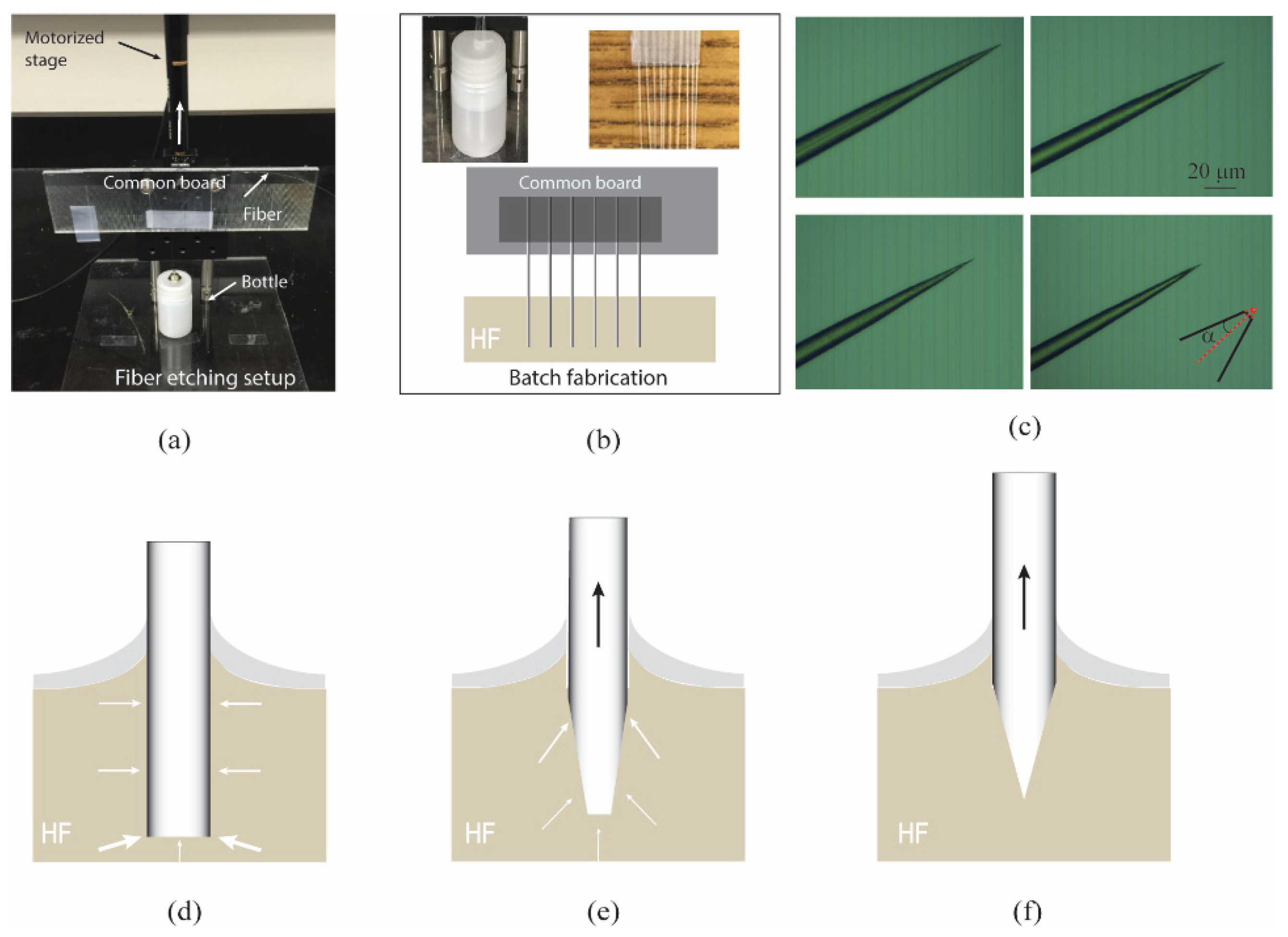
2.1. Unique Tubeless Chemical Etching Combined with Fiber Pulling

The etching method, in this work, is inspired by tube etching in ref. [29]. Unlike the tube etching method based on the micro−convection inside the polymer−coated tube and transient capillary effects, we removed the polymer−coated tube before the etching process since, based on the authors’ experience, it is very difficult to remove the tube mechanically without breaking the etched sharp tip of the fiber, resulting in a poor success rate (i.e., 20%).
To fabricate the fiber tip with a good quality of sharpness and smoothness, we used a chemical etching method, namely “tubeless” etching. Figure 1a,b show the single and batch fiber etching setups. Briefly, a single or the batch of optical fibers was striped by a mechanical striper and pre−attached to a motorized stage (PT1−Z8, THORLABS). The stripped fibers were then dipped vertically into Hydrofluoric (HF) acid with a protective layer of Toluene on the top. The HF acid used in the wet etching was diluted to the concentration of 40% in water. It is noted that, for batch etching, the small separation between the adjacent fibers can cause the asymmetrical and inadequate HF solution around each fiber and thus affect its surface quality. To overcome this issue, we separated the adjacent striped fibers with a distance of ~1 mm, as shown in Figure 1b (the upper right inset), by the customed grooves made on a regular glass slide. It thus enables the ample HF solution to surround each fiber, and the fiber is etched symmetrically. Figure 1b (the upper left inset) shows that a batch of fibers was well−separated and dipped into the HF solution. The schematic for the batch fiber etching is shown in Figure 1b.
Different to the static etching [30,31], the tip shape of the fiber is easily affected by the etching solution and environmental influences such as temperature drifts; here, we pulled the fibers upwards at a constant speed during the etching (the reasons discussed as below). Right after the fibers were inserted into HF, the fiber was pulled away by the motorized stage from the HF solution, with only a few seconds delay for one to turn on the stage. From the experiments, we found that the etching time and the pulling speed of fibers determine the geometry (opening angle, α (Figure 1c), diameter, d, and surface roughness) of the fiber tip. We carried out a simulation of the light confining effects and decided that the optimal fiber taper geometric parameters were α ≈ 8° and 200 nm < d < 2 μm. The detailed simulation results will be discussed in Section 3.1 and Figure 3. With these taper parameters and minimal taper surface roughness as our goal, we found that the optimized etching time and pulling speed were 60 min and 1 μm/s, respectively. The fiber tip was still immersed in the HF after the stage stopped after 60 min. We immediately took the etched fibers out of HF and rinsed them with water to stop etching. The typic microscopy images of the etched fibers are shown in Figure 1c. The α and d are estimated to be 6.5 ± 1.9 degrees and 300 ± 150 nm, respectively.
Figure 1d–f shows the schematics of the fiber tip formation during the etching process. Initially, the edge of the fiber end face is etched faster than the center due to the larger contact surface with HF solution, forming the fiber tapered shape, as shown in Figure 1d–e. During the etching process, HF attaches the glass fibers, and the reaction residuals can slow down the subsequent attack on the fiber surface. When the fiber is pulled upwards with a constant speed, due to the viscous drag force from the fluid, some reaction residuals will move with the fibers, resulting in the decreased diffusion around the fiber tip. This diffusion−induced etch slowdown can help retain the fiber tip in HF, leading to a sharp tip formed by the etching [29], as shown in Figure 1f. Different from a tubing outside the fiber used in [29], we used stripped fibers without any tubing formed outside the fiber in HF. The absence of the tubes prevented the sharp tips of the etch fibers from being accidentally broken when we took the fibers out of the HF etchant, in addition to removing the need for any additional efforts to remove the tube.

2.2. Working Principle of Fiber Taper Based Trapping

In the optical trap, optical forces arise from the momentum change of light resulting from scattering or refraction [32]. When a dielectric particle with a refractive index higher than the surrounding medium is shined by a focus laser beam, the particle diffracts the beam and experiences a force that is described as the sum of two components: a scattering force along the propagating direction of the laser beam and a gradient force along the gradient of the light intensity. Once these optical forces balance with all other forces that the particle is subject to, such as viscous drag force and gravity, a three−dimensional (3D) optical trap can be successfully created. In the dual etched fiber−based optical trapping system, the optical trapping is based on two inclined laser beams that have two sets of gradient forces and scattering forces, as shown in Figure 2b bottom.

2.3. Experimental Setup

The sub−micrometer particle trapping system was set up on a microscope platform. For the dual−fiber−taper−based system, light from a single−mode 980 nm laser diode (AC 1405−0400−0974−SM−500, Eques) was split into two etched fibers through a 50/50 fiber coupler. The light emitted from the etched fiber tapers was used to trap sub−micrometer particles. Each etched fiber was mounted on a common board, as shown in Figure 2a, and was aligned with respect to the other via a miniature 3D translational stage and a micro 1D rotational stage. The fiber inclination angle and fiber separation were also controlled by adjusting these stages. For the single−fiber−taper−based system, light from the laser source is directly coupled into the fiber without any couplers. The position of the optical trap from both systems was then adjusted by manipulating the common board via another 3D translational stage. In our trapping experiments, to reduce the fiber wobbling resulting from the mechanical drifts of the etched fibers in the optical trapping experiments, we used a metal tube to hold each fiber permanently via UV glue and kept the suspending length (define as the distance from the etched fiber tip to the end face of the metal tube) as ~4 mm.

3. Results

3.1. Optical Trapping by the Single−Fiber−Taper−BASED System

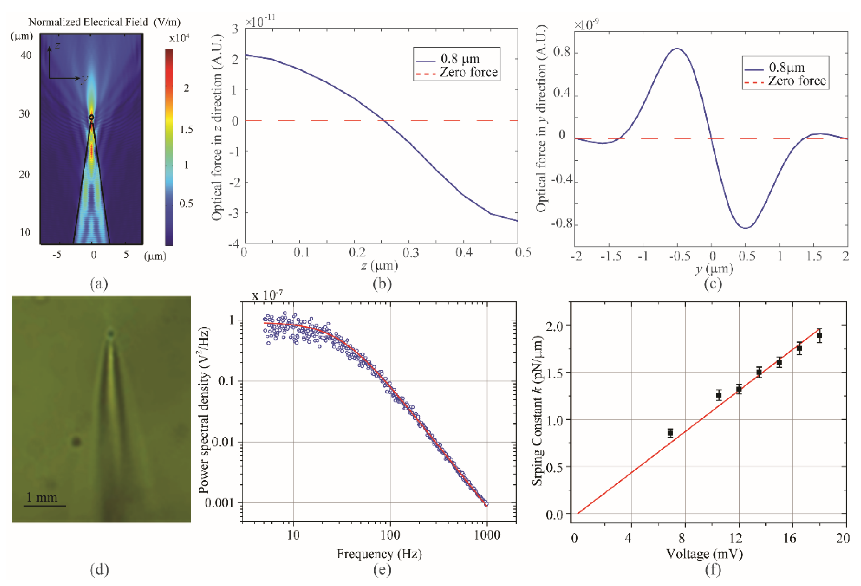
3.1.1. Simulation and Experimental Results of a Single−Fiber−Taper−Based Single Sub−Micrometer Particle Trapping

To study the optical trapping performance of the single−fiber−taper−based trapping system for a single sub−micrometer particle trapping, we numerically investigated the influence of the geometrical parameters of fiber, α and d, since both parameters determine the NA of the emitted light. For an etched fiber with a sharp tip, a small α = ~3° may cause the light to focus inside the fiber, while an α = 12° has a weak focus of the emitted light. For an etched fiber with an even larger α (30~45°), the emitted light has a clear focus, but these fibers need a long etching time. Based on the simulation results, the preferred α is ~8°. According to the numerical simulation, the NA of the emitted light is also influenced by the physical diameter of the fiber tip, d. For a fixed α = 8°, the emitted light has a strong focus when d is in the range of 200 nm to 2 μm. The focus of emitted light is weak for d > 2 μm. Etched fiber with d < 200 nm causes light to focus inside the fiber. In summary, the optimized parameters obtained from our simulation are α ≈ 8° and 200 nm < d < 2 μm, which agree with those from experiments, i.e., αexp ~ 6.7° and dexp ~ 300 nm, respectively.
Figure 3a shows the normalized electrical field when a particle (800 nm) is in the trap. Here, α and d used are 6.7° and 300 nm, respectively. In the simulation, we vary the particle position along the y- and z-axes and calculate the corresponding optical forces, as shown in Figure 3b,c. Accordingly, an 800 nm silica sphere can be 3D trapped ~250 nm away from the fiber tip along the optical axis by using an etched fiber. The experimental result of the 3D trapping of an 800 nm dielectric particle by a single etched fiber is shown in Figure 3d. The calibrated spring constant as a function of optical power is shown in Figure 3f. By fitting the power spectral density (PSD) of the confined Brownian motion of the trapped beam to a Lorentzian (Figure 3e), we estimated the characteristic corner frequency of the optical trap. With each experimentally determined corner frequency, we obtained the spring constant (the black square in Figure 3f) using the power spectrum analysis method [33,34,35,36]. It can be seen that there is a linear dependence of optical spring constant on optical power, as shown by the red straight line fitting in Figure 3f.

3.1.2. Optical Binding Effect

It is well known that trapping light interacts with one particle which could then interact with other particles in the field [37]. It can give rise to the inter−particle forces mediated by light; this effect is known as ‘optical binding’. Optical binding occurs when two or more particles in the field interact, forming a particle array [38]. According to the previous work [39], the existence of micro− or nano−objects in the counter−propagating laser fields causes the redistribution of light, which leads particles to form steady−state (spatial) configurations. The particle configurations, such as a line−shape pattern or complex geometries [40,41], are mainly determined by the field distribution, while the inter−particle spacing is determined by the refocusing and/or scattering of the laser fields by particles. Unlike the counter−propagating fiber trapping setup where optical bindings are mainly due to the repulsive forces, multiple particle trapping in this paper was based on the enhanced localized light gradient, which occurred when light passed through particles. Both single and dual−fiber−taper−based systems were used to demonstrate the simple line−shaped patterns of sub−micrometer particle trapping. Optical trapping of sub−micrometer particles in a complex geometry, such as a swarm pattern, was mainly realized by the dual−fiber−taper−based system.
Figure 4 shows that multiple 800 nm silica beads were trapped by a single etched fiber. This trap holds eight sub−micrometer particles due to the optical binding effect. We observed that the first seven nanoparticles were trapped very stably in a simple line shape (Figure 4a), and the last one could escape easily after around 30 s, as shown in Figure 4b. A new particle could be trapped later but not as stably as the first seven. Due to the optical binding effect, we managed to use a single etched fiber to trap multiple sub−micrometer particles in two dimensions, with the schematic shown in Figure 4c. However, the optical binding force was not strong enough to allow one to manipulate them in three dimensions.

3.2. Optical Trapping by Dual−Fiber−Taper−Based System

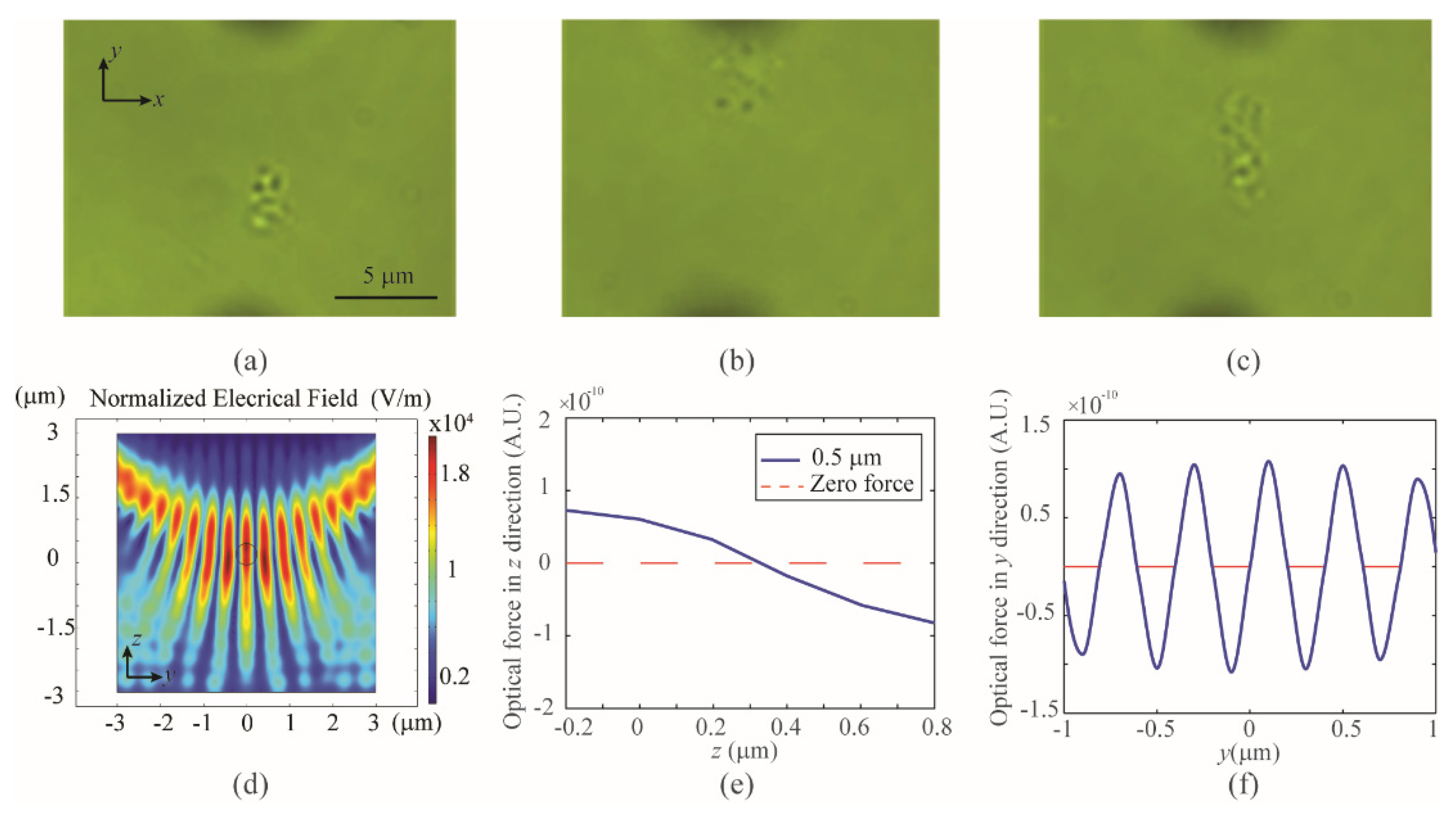
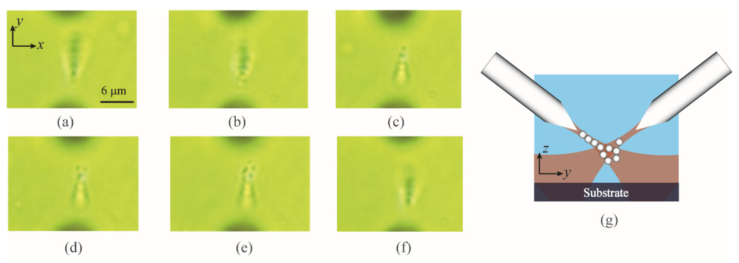
3.2.1. 3D Optical Trapping of a Swarm of Sub−Micrometer Particles

We used the dual−fiber−taper−based trapping system to trap and manipulate a swarm of sub−micrometer particles (in a complex pattern) in three dimensions. Silica beads with a size of 500 nm were used in this experiment. Figure 5a shows a swarm of 500 nm silica beads were trapped and manipulated 30 μm above the cover glass. The trapped swarm of sub−micrometer particles could be manipulated in the x- and y-directions but not in the z-direction. The failure of the manipulation, due to too fast movement of the dual−fiber system in the z-direction, as shown in Figure 5b. When the dual−fiber system was slowly moved back, the particle swarm was re−trapped. It is noted that, different from the single fiber trapping demonstrated in Figure 4, the particle swarm was trapped in three dimensions by the dual−fiber system, with the trapped position at least 30 μm above the cover glass. In the experiments, some particles entered the trap area, due to the Brownian motion [42], and these sub−micrometer particles also caused the number of particles to increase in the trap. Figure 5c shows the observed maximum number of particles in the 3D trap.
It is noted that 3D trapping of a swarm of sub−micrometer particles is more challenging than that of a single one. The trapping of sub−micrometer particles requires a strong optical intensity gradient, which is generally realized by tight spatial confinement of optical intensity. However, 3D stable trapping of a swarm of submicron particles requires a large intensity gradient in a wide area, which is challenging to realize, especially at a fiber tip. One possible reason for our success in the swarm sub−micrometer particle trapping is the interference of two laser beams, which resulted in the spatially alternating local intensity maxima and minima. Figure 5d shows the numerical simulation results of the interference patterns around the trap area when the distance of the two fibers is 6 μm. The interference of two laser beams forms multiple localized potential wells that can confine particles with a size comparable to the half wavelength of the laser beam. In our simulation, we use a 500 nm silica bead to map the optical force distribution in the z- and y-directions. The typical curves of optical force as a function of the bead position are shown in Figure 5e,f. In the simulation, we used two Gaussian beams, with waist and the inclined angle of 1 μm and 55°, respectively, to simulate the optical field in the trap. The parameters of the beam waist and inclined angle are determined based on the diameter of the fiber tip and the inclined angle of the two fibers in the experiment. This simulation indicates that interference patterns are a possible reason why a swarm of sub−micrometer particles was trapped in three dimensions, as we observed in the experiment.

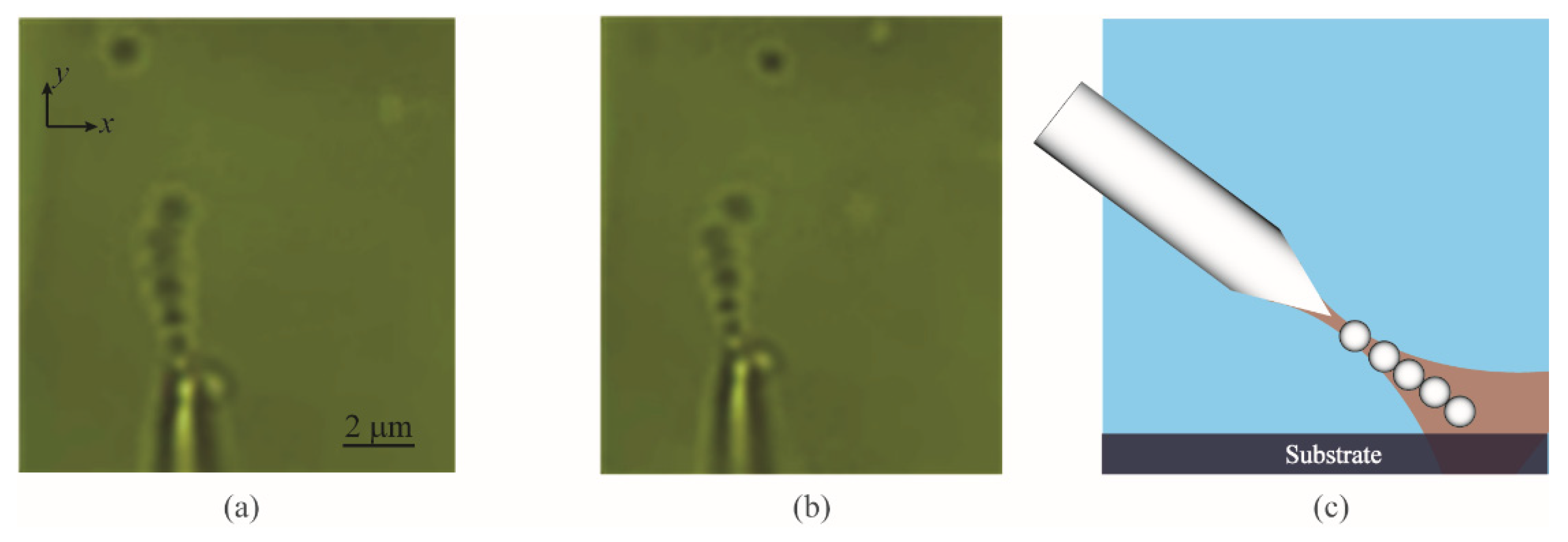
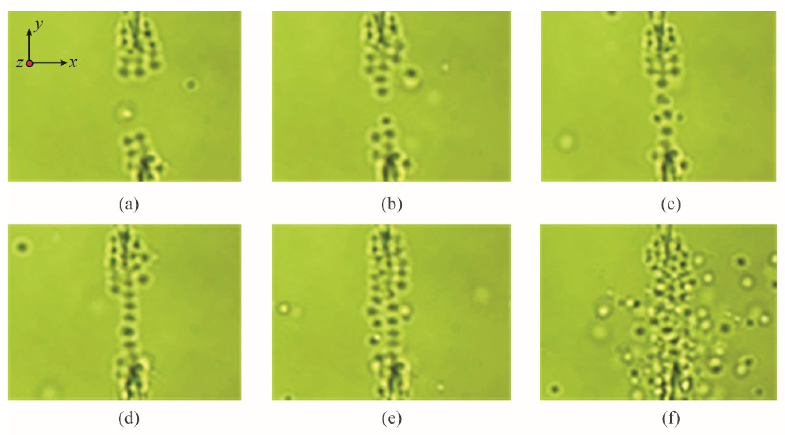
3.2.2. 3D Optical Trapping of the Sub−Micrometer Particles along Straight Lines Based on the Optical Binding Effect

The 3D manipulation of multiple sub−micrometer particles in a line−shaped pattern was carried out by using the dual−fiber−taper−based trapping system. Figure 6a–f shows optical trapping results. Nine 500 nm silica beads were trapped and manipulated in the z-direction. The objective lens was first focused at the fiber tips and then lowered down, as shown in Figure 6a–c. The blurry circular dots were the free beads on the cover glass. Due to the optical binding effect, seven particles were trapped and formed in a line−shaped pattern, as shown in Figure 6a,b. It is noted that there exists a trap area where two particles were trapped separately from the other seven particles, as shown in Figure 6c. It may be because of the NA difference between the emitted lights from two etched fibers. Another possible reason is that the light emitted from the lower fiber is modulated by the line−shaped particles, resulting in light redistribution. The modulated light field interferences with the light from the top fiber can form a localized light intensity gradient. As a result, it may generate extra potential wells to confine a group of particles separately. The number of trapped particles in this area was observed to increase after 30 s, as shown in Figure 6d,e. The initially trapped line−shaped particles due to optical binding effects were not affected by these increased new particles, as shown in Figure 6f. The schematic for trapping sub−micrometer particles by the dual−fiber−taper−based system is shown in Figure 6g.

3.2.3. Optical Guiding of Sub−Micrometer Particles in Two Dimensions

Optical guiding of microscopic particles is important in many applications, particularly in biology and colloidal physics [43]. It has been realized using a Gaussian beam [44], zeroth−order Bessel light beam [45], hollow Bessel−like beam [46], doughnut−shaped structured laser beam [47], and the plasma−based amplitude−modulated electromagnetic beam [48]. Both the continuous wave (CW) light beams [44,49] or femtosecond [11] laser sources have demonstrated the optical guiding of microscopic particles, such as aerosol droplets [45] or colloidal particles [43]. Here, we use the CW Gaussian beams from the dual−fiber−taper−based trapping system and observed that a large number of particles can be guided when the dual fiber system was moved close to the cover glass. Figure 7 shows the optical guiding of sub−micrometer particles with a size of 500 nm. The distance between the two fibers was kept as ~25 μm. Multiple particles were trapped initially around both fiber tips, as shown in Figure 7a. Both the line−shaped and swarm particle trappings (Figure 7a,b) were formed at the beginning. Interestingly, some particles were trapped surrounding the side edge of etched fiber; this is because, for this long−etched length fiber, some portion of light may be leaked out [50] due to a fabrication imperfection. The surface of the etched fiber may not be smooth enough to guide the light inside the fiber before being emitted at the fiber tip. The localized light intensity gradient due to the leaking light could be a source to confine particles at the side edge of the fiber. In the experiment, the number of particles increased fast along the optical axis due to the optical binding effect and the relatively strong light emitted from fiber tips. Therefore, the optical binding effect dominated the swarm behavior of the trapped particles, resulting in more particles “proceeding” along the straight line (optical axis), as shown in Figure 7c. The second group of particles trapped by the light from the lower fiber followed similar procedures until two groups of particles bond together (Figure 7d). The line−shaped particles formed in the middle of the trap turn into a “waveguide” that can guide the surrounding swarm particles and form the second line−shaped trapping (Figure 7e). It is noted that the violent Brownian motion of particles can disturb the optical binding effect and caused some particles to escape in the center of the trap. However, new particles enter quickly and make the 2D line−shaped trapping relatively stable. Finally, more particles were collected in the trap (Figure 7f). This is an environmentally friendly collection process and therefore may be a good way to recycle the important dielectric sub−micrometer particles.

4. Conclusions

By using a fiber pulling assisted tubeless method, we fabricated sharply tapered fibers that can be used to trap and manipulate sub−micrometer particles with a size down to 500 nm. We successfully realized the simple line−shaped particle trapping due to the optical binding effect by both single and dual−fiber−taper−based trapping systems. We also observed that a swarm of sub−micrometer particles (in a complex pattern) can be trapped in three dimensions. The possible reason for this new phenomenon is due to the interference between lights from two fibers, which causes the formation of multiple localized potential wells and results in trapping a swarm of sub−micrometer particles. In addition, we have demonstrated that the dual−fiber−taper−based strapping system can be used to guide and collect the massive particles in two dimensions. It is noted that etched fibers with a small opening angle and long etching length are fragile and may be broken when they are moved into contact with the substrate. However, dual etched fibers with an inclined angle can efficiently increase the working distance and enhance the optical trapping efficiency. Since the single etched fiber can be used to trap sub−micrometer particles in three dimensions, the dual fiber trapping system can be further minimized. Moreover, batch fabrication of etched fibers can be easily accomplished. The flexible adjustments of inclined angle and distance between fibers allow us to trap and manipulate a variety size of particles. This will make the dual−fiber−taper−based optical trapping system an attractive tool for many applications.

Supplementary Materials

The following are available online at https://www.mdpi.com/article/10.3390/photonics8090367/s1, Video S1: 3D trapping of a swarm of 500 nm silica beads, Video S2: Optical guiding by the dual etched fiber system.

Author Contributions

C.T. and Y.L. (Yuxiang Liu) conceived of the presented idea. Y.L. (Yuxiang Liu) supervised the research; C.T. set up the optical trapping system and performed the whole experiments; Y.S. helped with the optical trapping experiments and Y.L. (Yiming Lei) did the fiber taper etching. C.T. wrote the custom Matlab scripts for power spectrum analysis of the experimental data and all analytical calculations. C.T. performed the COMSOL simulations. C.T. and Y.L. (Yuxiang Liu) wrote the manuscript. All authors participated in discussions and data interpretation. All authors have read and agreed to the published version of the manuscript.

Funding

This research received no external funding.

Institutional Review Board Statement

Not applicable.

Informed Consent Statement

Not applicable.

Data Availability Statement

Not applicable.

Conflicts of Interest

The authors declare no conflict of interest.

References

  1. Ashkin, A. Acceleration and trapping of particles by radiation pressure. Phys. Rev. Lett. 1970, 24, 156. [Google Scholar] [CrossRef] [Green Version]
  2. Chang, D.E.; Regal, C.; Papp, S.; Wilson, D.; Ye, J.; Painter, O.; Kimble, H.J.; Zoller, P. Cavity opto-mechanics using an optically levitated nanosphere. Proc. Natl. Acad. Sci. USA 2010, 107, 1005–1010. [Google Scholar] [CrossRef] [PubMed] [Green Version]
  3. Romero-Isart, O.; Juan, M.L.; Quidant, R.; Cirac, J.I. Toward quantum superposition of living organisms. New J. Phys. 2010, 12, 033015. [Google Scholar] [CrossRef] [Green Version]
  4. Romero-Isart, O.; Pflanzer, A.C.; Blaser, F.; Kaltenbaek, R.; Kiesel, N.; Aspelmeyer, M.; Cirac, J.I. Large quantum superpositions and interference of massive nanometer-sized objects. Phys. Rev. Lett. 2011, 107, 020405. [Google Scholar] [CrossRef] [Green Version]
  5. Geraci, A.A.; Papp, S.B.; Kitching, J. Short-range force detection using optically cooled levitated microspheres. Phys. Rev. Lett. 2010, 105, 101101. [Google Scholar] [CrossRef] [PubMed] [Green Version]
  6. Hornberger, K.; Gerlich, S.; Haslinger, P.; Nimmrichter, S.; Arndt, M. Colloquium: Quantum interference of clusters and molecules. Rev. Mod. Phys. 2012, 84, 157. [Google Scholar] [CrossRef] [Green Version]
  7. Aspelmeyer, M.; Kippenberg, T.J.; Marquardt, F. Cavity optomechanics. Rev. Mod. Phys. 2014, 86, 1391. [Google Scholar] [CrossRef]
  8. Tayebi, M.; O’Rorke, R.; Wong, H.C.; Low, H.Y.; Han, J.; Collins, D.J.; Ai, Y. Massively Multiplexed Submicron Particle Patterning in Acoustically Driven Oscillating Nanocavities. Small 2020, 16, 2000462. [Google Scholar] [CrossRef]
  9. Schnelle, T.; Müller, T.; Gradl, G.; Shirley, S.G.; Fuhr, G. Dielectrophoretic manipulation of suspended submicron particles. Electrophor. Int. J. 2000, 21, 66–73. [Google Scholar] [CrossRef]
  10. Miao, X.; Wilson, B.K.; Pun, S.H.; Lin, L.Y. Optical manipulation of micron/submicron sized particles and biomolecules through plasmonics. Opt. Express 2008, 16, 13517–13525. [Google Scholar] [CrossRef] [Green Version]
  11. Morgan, H.; Hughes, M.P.; Green, N.G. Separation of submicron bioparticles by dielectrophoresis. Biophys. J. 1999, 77, 516–525. [Google Scholar] [CrossRef] [Green Version]
  12. Čižmár, T.; Garcés-Chávez, V.; Dholakia, K.; Zemánek, P. Optical conveyor belt for delivery of submicron objects. Appl. Phys. Lett. 2005, 86, 174101. [Google Scholar] [CrossRef] [Green Version]
  13. Svoboda, K.; Schmidt, C.F.; Schnapp, B.J.; Block, S.M. Direct observation of kinesin stepping by optical trapping interferometry. Nature 1993, 365, 721–727. [Google Scholar] [CrossRef] [PubMed]
  14. Finer, J.T.; Simmons, R.M.; Spudich, J.A. Single myosin molecule mechanics: Piconewton forces and nanometre steps. Nature 1994, 368, 113–119. [Google Scholar] [CrossRef] [PubMed]
  15. Peterman, E.J.; Gittes, F.; Schmidt, C.F. Laser-induced heating in optical traps. Biophys. J. 2003, 84, 1308–1316. [Google Scholar] [CrossRef] [Green Version]
  16. Rowe, A.D.; Leake, M.C.; Morgan, H.; Berry, R.M. Rapid rotation of micron and submicron dielectric particles measured using optical tweezers. J. Mod. Opt. 2003, 50, 1539–1554. [Google Scholar] [CrossRef]
  17. Chen, Y.-F.; Blab, G.A.; Meiners, J.-C. Stretching submicron biomolecules with constant-force axial optical tweezers. Biophys. J. 2009, 96, 4701–4708. [Google Scholar] [CrossRef] [PubMed] [Green Version]
  18. Zhang, Y.; Liu, Z.; Yang, J.; Yuan, L. A non-contact single optical fiber multi-optical tweezers probe: Design and fabrication. Opt. Commun. 2012, 285, 4068–4071. [Google Scholar] [CrossRef]
  19. Tong, L.; Gattass, R.R.; Ashcom, J.B.; He, S.; Lou, J.; Shen, M.; Maxwell, I.; Mazur, E. Subwavelength-diameter silica wires for low-loss optical wave guiding. Nature 2003, 426, 816–819. [Google Scholar] [CrossRef]
  20. Li, H.; Zhang, Y.; Li, J.; Qiang, L. Observation of microsphere movement driven by optical pulse. Opt. Lett. 2011, 36, 1996–1998. [Google Scholar] [CrossRef] [PubMed]
  21. Constable, A.; Kim, J.; Mervis, J.; Zarinetchi, F.; Prentiss, M. Demonstration of a fiber-optical light-force trap. Opt. Lett. 1993, 18, 1867–1869. [Google Scholar] [CrossRef]
  22. Taylor, R.; Hnatovsky, C. Particle trapping in 3-D using a single fiber probe with an annular light distribution. Opt. Express 2003, 11, 2775–2782. [Google Scholar] [CrossRef] [PubMed]
  23. Ashkin, A. Forces of a single-beam gradient laser trap on a dielectric sphere in the ray optics regime. Biophys. J. 1992, 61, 569–582. [Google Scholar] [CrossRef] [Green Version]
  24. Wei, M.-T.; Yang, K.-T.; Karmenyan, A.; Chiou, A. Three-dimensional optical force field on a Chinese hamster ovary cell in a fiber-optical dual-beam trap. Opt. Express 2006, 14, 3056–3064. [Google Scholar] [CrossRef]
  25. Jess, P.; Garcés-Chávez, V.; Smith, D.; Mazilu, M.; Paterson, L.; Riches, A.; Herrington, C.; Sibbett, W.; Dholakia, K. Dual beam fibre trap for Raman microspectroscopy of single cells. Opt. Express 2006, 14, 5779–5791. [Google Scholar] [CrossRef]
  26. El Eter, A.; Hameed, N.M.; Baida, F.I.; Salut, R.; Filiatre, C.; Nedeljkovic, D.; Atie, E.; Bole, S.; Grosjean, T. Fiber-integrated optical nano-tweezer based on a bowtie-aperture nano-antenna at the apex of a SNOM tip. Opt. Express 2014, 22, 10072–10080. [Google Scholar] [CrossRef] [PubMed]
  27. Mivelle, M.; van Zanten, T.S.; Neumann, L.; van Hulst, N.F.; Garcia-Parajo, M.F. Ultrabright bowtie nanoaperture antenna probes studied by single molecule fluorescence. Nano Lett. 2012, 12, 5972–5978. [Google Scholar] [CrossRef]
  28. Mondal, S.K.; Pal, S.S.; Kapur, P. Optical fiber nano-tip and 3D bottle beam as non-plasmonic optical tweezers. Opt. Express 2012, 20, 16180–16185. [Google Scholar] [CrossRef]
  29. Stöckle, R.; Fokas, C.; Deckert, V.; Zenobi, R.; Sick, B.; Hecht, B.; Wild, U.P. High-quality near-field optical probes by tube etching. Appl. Phys. Lett. 1999, 75, 160–162. [Google Scholar] [CrossRef]
  30. Okayama, T.; Seki, H. Fabrication and evaluation of silica-based optical fiber probes by chemical etching method. Opt. Rev. 2005, 12, 25–28. [Google Scholar] [CrossRef]
  31. Tao, M.; Jin, Y.; Gu, N.; Huang, L. A method to control the fabrication of etched optical fiber probes with nanometric tips. J. Opt. 2009, 12, 015503. [Google Scholar] [CrossRef]
  32. Svoboda, K.; Block, S.M. Biological applications of optical forces. Annu. Rev. Biophys. Biomol. Struct. 1994, 23, 247–285. [Google Scholar] [CrossRef] [PubMed]
  33. Berg-Sørensen, K.; Flyvbjerg, H. Power spectrum analysis for optical tweezers. Rev. Sci. Instrum. 2004, 75, 594–612. [Google Scholar] [CrossRef] [Green Version]
  34. Ti, C.; Ho-Thanh, M.-T.; Wen, Q.; Liu, Y. Objective-lens-free Fiber-based Position Detection with Nanometer Resolution in a Fiber Optical Trapping System. Sci. Rep. 2017, 7, 13168. [Google Scholar] [CrossRef] [PubMed] [Green Version]
  35. Ti, C.; Thomas, G.M.; Ren, Y.; Zhang, R.; Wen, Q.; Liu, Y. Fiber based optical tweezers for simultaneous in situ force exertion and measurements in a 3D polyacrylamide gel compartment. Biomed. Opt. Express 2015, 6, 2325–2336. [Google Scholar] [CrossRef] [PubMed] [Green Version]
  36. Ti, C.; Shen, Y.; Thanh, M.-T.H.; Wen, Q.; Liu, Y. Reliable and mobile all-fiber modular optical tweezers. Sci. Rep. 2020, 10, 1–11. [Google Scholar] [CrossRef]
  37. Tatarkova, S.; Carruthers, A.; Dholakia, K. One-dimensional optically bound arrays of microscopic particles. Phys. Rev. Lett. 2002, 89, 283901. [Google Scholar] [CrossRef] [Green Version]
  38. Burns, M.M.; Fournier, J.-M.; Golovchenko, J.A. Optical binding. Phys. Rev. Lett. 1989, 63, 1233. [Google Scholar] [CrossRef] [Green Version]
  39. Karásek, V.; Dholakia, K.; Zemánek, P. Analysis of optical binding in one dimension. Appl. Phys. B 2006, 84, 149. [Google Scholar] [CrossRef]
  40. Burns, M.M.; Fournier, J.-M.; Golovchenko, J.A. Optical matter: Crystallization and binding in intense optical fields. Science 1990, 249, 749. [Google Scholar] [CrossRef] [Green Version]
  41. Ng, J.; Lin, Z.; Chan, C.; Sheng, P. Photonic clusters formed by dielectric microspheres: Numerical simulations. Phys. Rev. B 2005, 72, 085130. [Google Scholar] [CrossRef] [Green Version]
  42. Li, T.; Kheifets, S.; Medellin, D.; Raizen, M.G. Measurement of the instantaneous velocity of a Brownian particle. Science 2010, 328, 1673–1675. [Google Scholar] [CrossRef] [PubMed] [Green Version]
  43. Fischer, P.; Carruthers, A.; Volke-Sepulveda, K.; Wright, E.M.; Brown, C.; Sibbett, W.; Dholakia, K. Enhanced optical guiding of colloidal particles using a supercontinuum light source. Opt. Express 2006, 14, 5792–5802. [Google Scholar] [CrossRef] [PubMed]
  44. Carruthers, A.; Tatarkova, S.A.; Garces-Chavez, V.; Volke-Sepulveda, K.; Chavez-Cerda, S.; Dholakia, K. Optical guiding using Gaussian and Bessel light beams. In Proceedings of the Laser Processing of Advanced Materials and Laser Microtechnologies, Moscow, Russia, 22–27 June 2002; pp. 68–76. [Google Scholar]
  45. Summers, M.; Reid, J.; McGloin, D. Optical guiding of aerosol droplets. Opt. Express 2006, 14, 6373–6380. [Google Scholar] [CrossRef]
  46. Eckerskorn, N.; Li, L.; Kirian, R.A.; Küpper, J.; DePonte, D.P.; Krolikowski, W.; Lee, W.M.; Chapman, H.N.; Rode, A.V. Hollow Bessel-like beam as an optical guide for a stream of microscopic particles. Opt. Express 2013, 21, 30492–30499. [Google Scholar] [CrossRef]
  47. Eckerskorn, N.O. Trapping and Guiding Microscopic Particles with Light-Induced Forces; Australian National University: Canberra, Australia, 2016. [Google Scholar]
  48. Singh, M.; Gupta, D. Plasma based optical guiding of an amplitude-modulated electromagnetic beam. In Proceedings of the International Conference on Optics and Photonics, Kolkata, India, 15 June 2015; p. 96541R. [Google Scholar]
  49. Arlt, J.; Dholakia, K.; Soneson, J.; Wright, E.M. Optical dipole traps and atomic waveguides based on Bessel light beams. Phys. Rev. A 2001, 63, 063602. [Google Scholar] [CrossRef] [Green Version]
  50. Pisanello, F.; Mandelbaum, G.; Pisanello, M.; Oldenburg, I.A.; Sileo, L.; Markowitz, J.E.; Peterson, R.E.; Della Patria, A.; Haynes, T.M.; Emara, M.S.; et al. Dynamic illumination of spatially restricted or large brain volumes via a single tapered optical fiber. Nat. Neurosci. 2017, 20, 1180–1188. [Google Scholar] [CrossRef] [PubMed] [Green Version]
Figure 1. The fiber pulling assisted tubeless chemical etching setup for (a) a single fiber and (b) a batch of fibers. Either a single fiber (a) or a batch of fibers (b, upper right inset) were attached to a motorized stage via a plastic common board. The attached fiber or a batch of fibers were inserted into an HF−filled plastic bottle (b, upper left inset) and moved upwards at a constant speed. The value of the speed, which is related to the etching time and determines the opening angle (α, bottom right of (c)) and surface quality of the fiber, was optimized as 1 μm/s and 60 min, respectively. For the batch fiber etching, the adjacent fibers are separated at a distance of ~1 mm. (c) Typical microscopic images of multiple fiber tapers resulting from a single fabrication batch. (df) The fiber tip formation by chemical etching. (df) The schematics of the initial, intermediate, and final stages of the etching process of a single optical fiber, respectively. The white arrows point to the directions of the etching. The arrow thickness represents the etch rate with thicker ones for faster rates. The black arrows represent the moving direction of the fiber, which was controlled by the motorized stage, during the etching process.
Photonics 08 00367 g001
Figure 2. (a) Experimental setup and (b) working principle of the single (top) and inclined dual etched fiber−based optical trapping system (bottom). Fs = scattering force; Fg = gradient force. The inclined angle is defined as the angle between a fiber and the vertical direction. The gravity and buoyancy forces are not drawn.
Photonics 08 00367 g002
Figure 3. Numerical simulations and the experimental demonstration of the 3D trapping for a single submicron particle by a single fiber−based system. (a) Numerical simulation of a normalized electrical field when an 800 nm silica bead is trapped by the single etched fiber. (b,c) The simulated optical forces as a function of the particle position along the y- and z-axes, respectively. (d) The 3D optical trapping of an 800 nm silica bead by a single etched fiber is mounted at 45−degree with a vertical axis. The 10× objective is used in this experiment. (e) The PSD of the motion of the trapped particle as a function of frequency. The corner frequency is obtained by fitting the PSD to a Lorentzian. The red curve in (e) is the fitted Lorentzian. (f) The linear dependency of the calibrated spring constant on the optical power. The black data points with error bars are the experimental data and the straight red line is the fitted line passing through (0,0).
Photonics 08 00367 g003
Figure 4. Demonstration of the optical binding effect. (a) Eight submicron particles trapped by the single fiber−based trapping system. The first 7 particles are stably trapped while the last one can easily escape from the trap (b) due to the weak light coupling. The blurry circle dot at the right−hand side of the fiber tip is a free particle on the cover glass. (c) The schematic diagram for trapping multiple submicron particles, due to the optical binding effect, by a single fiber−based system.
Photonics 08 00367 g004
Figure 5. 3D trapping of a swarm of 500 nm silica bead particles by the dual etched fiber system. A swarm of beads trapped (a) and manipulated 30 μm above the substrate. (b) When the dual−fiber system was moved too fast in the z−direction, the particle swarm escaped from the trap (seconds 8~11 in the Video S1). The swarm was re−trapped when the fiber system was moved back to the original height (second 12 in the Video S1). The number of beads is increased in the trap due to their violent Brownian motion. (c) The observed maximum number of particles in the trap (second 15 in the Video S1). The oil immersion 100x objective lens is used in this experiment. (d) Numerical simulation of the normalized electrical fields when two etched fibers are separated by 6 μm (e) and (f) the simulated optical forces applied onto a 500 nm silica sphere when it was moved along the z- (y = 0) and the y- (z = zequilibrium) directions.
Photonics 08 00367 g005
Figure 6. 3D trapping of multiple submicron particles by a dual etched fiber−based system. Multiple particles are 3D trapped in a straight line due to the optical binding effect (a) and (b). Microscope images taken when the objective lens is focused at the fiber tips (a) and particles (b). (c) An additional group of particles trapped close to the upper fiber. The number of particles in the group is increased (d) and (e). (f) No influence of the increased number of the cluster particle on the trapped particles due to the optical binding effect. The bright−field images taken through an oil immersion 100× objective lens. (g) The schematic for trapping multiple submicron particles in three dimensions by a dual−fiber−taper−based trapping system.
Photonics 08 00367 g006
Figure 7. Massive particles trapping in two dimensions by a dual etched fiber system. Particles are trapped around both fiber tips at the beginning (a) and guided in a straight line due to the optical binding effect (bd). Particles start to be guided in the second straight line (left) (e). (f) Generation of massive particles collection. The particles used in this experiment are silica beads with a size of 500 nm. The 100x oil immersion objective is used in this experiment. The two fibers are aligned along the y-axis in the yz plane and the submicron particles are guided along the y-axis in the xy plane.
Photonics 08 00367 g007
Publisher’s Note: MDPI stays neutral with regard to jurisdictional claims in published maps and institutional affiliations.

