Abstract
Mechanical properties of metallic-nanowire self-oscillations are investigated through a coherent-state analysis. We focus on elucidating the time behavior of quantum energy in such oscillations, in addition to the analysis of fluctuations, evolution of eigenstates, and oscillatory trajectories. The quantum energy varies somewhat randomly at first, but, at a later time, it undergoes a stable periodical oscillation; the mean energy in the stabilized motion is large when the frequency of the driving force is resonated with that of the intrinsic oscillation of the nanowire. We confirmed that when the oscillatory amplitude is sufficiently low, the quantum energy is quite different from the classical one due to zero-point energy which appears in the quantum regime. Because the power in such an oscillation is typically ultra low, quantum effects in the nanowire oscillations are non-negligible. Detailed analysis for the evolution of the probability densities and their relation with the oscillation trajectories of the nanowire are also carried out. Characterizing quantum effects in the actual oscillatory motions and clarifying their difference from the classical ones are important in understanding nanowire self-oscillations.
1. Introduction
The achievement of technological breakthroughs in next-generation nanoelectromechanical systems (NEMSs) may be possible only when we can efficiently control light–matter interactions [1]. It is highly required to develop high-speed autonomous nanoelectronic devices such as nanoresonators and signal generators through advanced NEMS technologies. As a consequence, the mechanism of nanoelectromechanical oscillations in nano and photonic devices has been extensively investigated during the past several decades. Nanoelectromechanical systems that adopt nanowire resonances have become important in nanomechanics on account of their potential applicability in diverse fields of the state-of-the-art nanotechnology, such as timing/switching [2,3], ultrasensitive mechanical detection and resolution [4,5], single electron resonance tuning [6,7], and radio-wave receptors [8,9].
In particular, self-oscillating nanowires [10,11,12,13,14,15,16,17,18,19,20] are noticeable because of their usefulness as a tool for on-chip controllable electronic actuations [10] and producing field emissions [11,12]. Self-oscillation of nano and micromechanical resonators can be produced by feedback from external amplifiers [13,14]. Alba et al. recently suggested self-oscillations of nanowires operated by photothermal forces prepared using a laser beam [13]. They achieved nanowire self-oscillations at low power thresholds of incident driving light less than 1 W. Because the power in such an oscillation is ultra low, it is desired to treat the system quantum mechanically in general, instead of the classical analysis [20,21].
Self-oscillations of nanowires occur due to the periodical electrostatic force acting on them, which compensates for air damping. The incident laser beam and a reflecting Si mirror will produce the standing wave, which acts as the origin of the driving force for the nanowire deposited between them. The setup of this system requires less stringent criterion for the degree of the ambient vacuum, leading to new flexible device applications with smaller device footprints. For more details of the mechanism of nanowire self-oscillations, including the enhancement of the quality factor and the photothermal effects on the oscillatory motion, refer to reference [13] and references therein. The theoretical understanding of the oscillatory behavior of the system and the proper analysis of their underlying features may be crucial in order to support the interpretation of associated experimental outcomes.
The purpose of this work is to investigate quantum effects in nanowire self-oscillations by introducing a coherent-state model for their quantum description [22]. To this end, we regard nanowire oscillations induced by periodically varying external forces. Especially, we focus on elucidating the characteristics of the resultant quantum energy. The coherent states heavily resemble classically oscillating states, allowing quantum-classical correspondence for a certain situation, i.e., in the classical limit. However, the differences in the evolution of quantum observables with the classical counterparts are important, especially in the low oscillation-energy limit because of the prominence of quantum effects in that situation. In this regard, the analysis in our research may provide a deeper insight for characterizing the oscillatory motion of nanowires.
The nanowire oscillations are actually described by time-dependent Hamiltonians due to the periodic external force and the damping factor. Such Hamiltonian systems will be described with the annihilation and the creation operators associated with the harmonic oscillator (HO). Based on this description, we will analyze the evolution of the system in detail and will compare the consequences with those of the classical analysis.
2. Methods
To analyze temporal evolution of nanowire self-oscillations, we first need to describe their oscillatory motion. We consider an optically absorbing bimetallic nanowire of which the substance is SiN-Nb for convenience, which was used in reference [13]. The size of the sample nanowire reported in reference [13] is 40 m × 55 nm × 25 nm (length × width × thickness). However, without difficulty, our study can also be extended to other cases of nanowire self-oscillations of which material and its size are different.
In principle, it is possible to describe nanowire oscillations quantum mechanically regardless of the size of a nanowire. However, such a description may especially be useful when the mechanical description of the oscillation cannot be covered by classical mechanics. From an experimentally supported theory of quantum mechanics, it is known that quantum effects are non-negligible when the dimension of material is less than the Fermi wavelength [23].
The type of material may also affect the measure of quantum effects. Regarding this, quantum effects in the oscillation are relatively prominent when the stiffness (spring constant) of the material is large; this is due to the fact that quantum zero-point energy is proportional to the oscillatory frequency, i.e., square root of the spring constant.
The oscillation of the nanowire is driven by a standing wave that is prepared by an incident laser beam and a reflecting mirror. A sinusoidal photothermal force induces a self-oscillation of the nanowire of which either side is clamped. The classical equation of motion for such an oscillation can be written as [13]
where is the effective damping factor, is the effective angular frequency, and is the amplitude of the photothermal force divided by the nanowire mass and is the driving frequency. For detailed formulae of and , see, for example, reference [13].
The quantum Hamiltonian of the system is represented as
This is obtained by replacing canonical variables x and p in the classical Hamiltonian with quantum operators and , respectively. In other words, if we replace and with x and p from Equation (2), we have the classical Hamiltonian. Based on Hamilton’s equations
we can easily confirm that such a classical Hamiltonian yields Equation (1).
Using the annihilation operator and its hermitian adjoint (creation operator), this Hamiltonian can be rewritten in the form
We can express the eigenvalue equation of the annihilation operator as
where is the eigenvalue and is the eigenstate. Notice that the eigenstate in this case is the well-known Glauber coherent state [22].
The expectation value of the Hamiltonian in the coherent state is given by
From the use of Equation (4) together with the relations
we readily have
In the next section, this formula will be used in order to study the time behavior of the system in the coherent state.
3. Results and Discussion
3.1. Solution for the Eigenvalue
To see time evolution of observables in the coherent state, it is necessary to know how evolves in time. The time evolution of can be analyzed from the Euler–Lagrange equation, which is given by
where is a Poisson bracket of the form [24]
A simple evaluation after substituting Equation (8) into Equation (9) leads to
To solve this differential equation, we divide into real and imaginary parts such that
where and are real. Then, we easily confirm that the real and imaginary parts of Equation (11) are given respectively by
We confirm, using these two equations, that satisfies the differential equation of the form
On the other hand, can be directly identified from Equation (13) once is determined from Equation (15).
From basic mechanics, the solution of in Equation (15) (and consequently, ) is composed of a complementary solution () and a particular solution (), such that
A minor evaluation using Equation (15) together with Equation (13) gives the complementary and the particular solutions as
where , , , is a constant, and is an arbitrary phase. Here, is an inverse function of , where the valid range of this function is . The complete solution of given above will be used in estimating the quantum time behavior of the system in the subsequent subsections.
3.2. Fluctuations
Now, we see the fluctuations of canonical variables which are expressed in terms of the ladder operators as
The fluctuation of an arbitrary operator in the coherent state can be defined to be
For the case of canonical variables given in Equations (22) and (23), we easily have
Equation (5) has been used in these derivations. We can see that these two fluctuations give the exact minimum uncertainty product . However, if we use the physical momentum that is defined by (see Equation (A2) in Appendix A and reference [25]) instead of the canonical momentum, the uncertainty product is given by
This vanishes in the long time limit, whereas the value of does not vary at all times. However, in the HO limit where , Equation (27) also becomes a constant value , which is the minimum uncertainty.
3.3. Evolution of the Quantum Energy
We now turn our attention to the quantum mechanical energy. Unlike the classical energy, quantum energy is different depending on given quantum states. For instance, it is well known that quantum energy is discrete and involves a zero-point energy in the Fock state. For the case of the coherent state that we treat now, quantum energy is determined in terms of .
It is well known that the energy operator of a nonstationary system is different from the Hamiltonian. The energy operator in this dissipative system is given by [26,27]
This can be obtained from Equation (A3) in Appendix A via the replacement of x and p by operators and , respectively. The evaluation for the expectation value of this operator in the coherent state gives the quantum energy:
In the derivation of this quantity, we have used Equations (22) and (23) together with Equation (7). We have illustrated the time evolution of the quantum energy and the corresponding Hamiltonian in Figure 1, Figure 2 and Figure 3. Figure 1 shows that, while the expectation value of the Hamiltonian increases with time, the quantum energy dissipates. Such a dissipation is more significant when is large. However, the quantum energy cannot be lowered below a certain value because of the existence of the intrinsic uncertainty in quantum observables, including the quantum energy. The magnitude of is determined by the air pressure in the experimental chamber. Hence, in order to diminish its magnitude, the degree of vacuum in the chamber should be kept high.
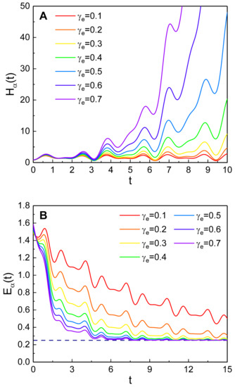
Figure 1.
The dependence of time evolution of the Hamiltonian expectation value (A) and the quantum energy (B) on . The values that we have used are , , , , , , and . The reference line (dashed line) in the bottom part of (B) is 0.25, which is the minimum value of the quantum energy in this model; this rule will also be applied in the subsequent figures of the quantum energy (Figure 2C and Figure 3C).
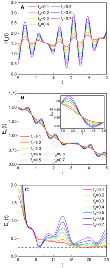
Figure 2.
The time evolution of (A) and (B,C) depending on , where for (A,B), while for (C). The values that we have used are , , , , , and . The difference of (C) from (B) is only the value of the taken .
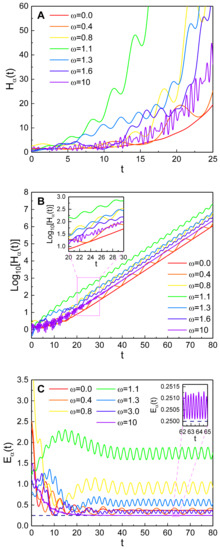
Figure 3.
The effects of on the time evolution of (A,B) and (C). (B) is a log-scale graph for a relatively long time. The values that we have used are , , , , , , and .
From Figure 2, we see that both the Hamiltonian and the quantum energy oscillate according to the driving force. Figure 2A,B shows that the Hamiltonian and the quantum energy oscillate rapidly depending on the driving frequency , provided that . On the other hand, for the case given in Figure 2C, the quantum energy varies with a relatively high amplitude. Figure 2B,C shows that if the amplitude of the external driving force is high (i.e., is large), the variation of the energy becomes significant. An entrainment of the self-oscillation occurs if the driving force is sufficiently high [13,28,29]. Then, the nanowire oscillates according to the driving frequency rather than its natural frequency.
Figure 3 reveals that the driving frequency is also a critical factor on the evolution pattern of the quantum energy and the Hamiltonian. If is near , the increase of the Hamiltonian over time is very rapid (see the green curves in Figure 3A,B). On the other hand, we see from Figure 3C that the quantum energy steadily oscillates over time when t is sufficiently large; in this case, the mean energy is relatively high when is near the resonance one. The frequency of such an energy oscillation increases as grows. In an extreme case where (the violet curve in Figure 3C), the frequency of the energy oscillation is very large while the oscillation does not thoroughly disappear even after a long lapse of time (see the inset in Figure 3C). Because in the limit , the quantum energy represented in Equation (29) eventually becomes
after a sufficient long time. However, if we consider that exponentially dissipates over time according to Equation (18), the energy expression in Equation (30) can be further simplified to
Hence, in a long time limit, the quantum energy oscillates depending on which is the oscillation frequency of . This is the reason why Figure 3C shows the increase of the oscillation frequency of in the stabilized situation as grows.
By comparing Equations (18) and (19), we see that is involved in , whereas does not involve it. For this reason, if the amplitude grows, (and hence ) increases monotonically at first. However, when t is sufficiently large, the influence of on quantum energy is negligible because the right-hand side of Equation (31) is independent of . For the non-driven case (), the quantum energy reduces to the case of a simple dissipative oscillator, which is shown in Equation (A16) of reference [30].
Figure 4 is the comparison of the quantum energy with the corresponding classical energy described in Appendix A. For the case that the oscillation amplitude of the nanowire is small, quantum energy is quite different from the classical energy (see Figure 4A). The instantaneous minimum values of the quantum kinetic energy and the quantum potential energy are not zero, whereas their classical counter parts are zero. However, we see from Figure 4B that the quantum and the classical energies are very much the same when the oscillation amplitude is sufficiently high. The second term in the right-hand side of Equation (31) gives the lowest limit of the quantum energy, which is for a large t. It may be possible to neglect quantum effects in the oscillation if the oscillatory energy is 1000 times larger than this base energy; hence, a rough critical energy that divides the low and high energies is . For example, for the case that the effective frequency is given by , the critical energy is estimated to be J.
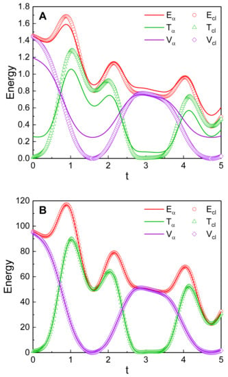
Figure 4.
Comparison of the quantum energy with the classical energy for a low (A) and a relatively high (B) amplitude regime. , , and are the total quantum energy, the quantum kinetic energy, and the quantum potential energy, whereas , , and are the total classical energy, the classical kinetic energy, and the classical potential energy, respectively. The taken values of (, , ) are (1, 1.74, 1) for (A) and (10, 14.2, 10) for (B). Other values that we have used are , , , , , and .
3.4. Analysis of the Eigenstate
Now we see the evolution of the coherent state , which is the eigenstate in Equation (5). The solution of Equation (5) in the configuration space is given by
For the case of and , we have ; then, the above eigenstate exactly recovers to that of the simple harmonic oscillator, which appeared in reference [31].
The evolution of the probability density can be seen from Figure 5. The position, in which the probability density takes a peak value, oscillates and converges toward the origin over time at first. However, it does not totally collapse even after a long lapse of time; in this case, the remained oscillation with a reduced amplitude is due to the external driving force. If the power supplied from the laser beam is suspended, such a residual oscillation will be quenched eventually. However, even in that case, the width of the probability density in the configuration space may not vanish. The probability density left in the non-zero position in this case is intrinsically related to the minimum uncertainty.
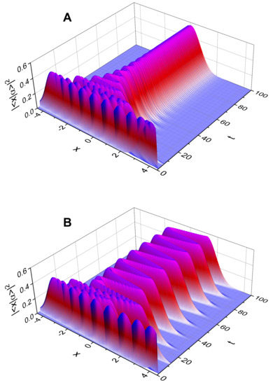
Figure 5.
Time evolution of the probability density for (A) and (B). The values that we have used are , , , , , , and .
Figure 5A is for while Figure 5B is the case . A careful observation of Figure 5A reveals that the associated probability density exhibits a rapid oscillation with a tiny amplitude due to the relatively high value of the driving-force frequency. On the other hand, the probability density in Figure 5B oscillates with a relatively huge amplitude even when t is sufficiently large as a consequence of the smallness of the driving frequency ; recall, from Figure 2C, that the quantum energy also deviates highly when is small.
It may also be noteworthy to analyze the behavior of the probability densities when the driving frequency approaches amplitude resonance frequency, . We have depicted the evolution of together with the momentum probability density for a nearly resonated system in Figure 6. For the plot of , we used the Fourier transformation of Equation (32). Figure 6A,B shows that both the position expectation value and the classically evaluated position (the momentum expectation value and the classical canonical momentum ) closely follow the trajectory of the most probable value of (). For the case of the resonance or near resonance where is sufficiently large, and are dominant compared to and , respectively (see Equations (18)–(21)). Due to this, the probability density in Figure 6A oscillates with a relatively high amplitude even when t is large. On the other hand, oscillatory amplitudes of and the canonical momenta and diverge exponentially over time. In addition, the physical momentum does not diverge but oscillates fairly uniformly.
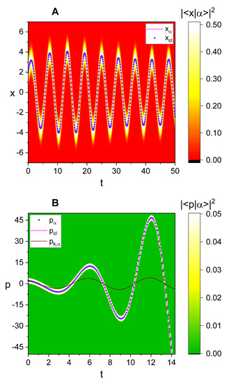
Figure 6.
(A): Comparison of the time evolution of the probability density (density plot) with that of the quantum expectation value () and its classical counter part represented in Equation (A4). (B): Comparison of the time evolution of the momentum probability density (density plot) with that of the quantum expectation value (), (Equation (A5)), and the expectation value of the physical momentum (). is used for both panels (A,B); this case corresponds to near resonance like that of the green curves in Figure 3. Other values that we have used are , , , , , , , and .
4. Conclusions
We have investigated the time evolution of nanowire self-oscillations activated by an incident laser beam in the coherent state. The quantum solution of the system has been obtained from the fundamental Hamiltonian dynamics. We have focused on time behavior of the quantum energy based on its rigorous analytical evaluation. The effects of the variations of several parameters on the evolution of the quantum energy have been analyzed using various relevant illustrations.
It turned out that the external driving force gravely affects the nanowire oscillation. Although the quantum energy dissipates over time at first, it becomes a steadily oscillating stable value at a later time where the average energy dissipated by damping is entirely compensated by the external driving force. The mean energy in the stabilized oscillation becomes high when the driving frequency approaches the resonance frequency; this means that the resonance is important in order to maintain the nanowire oscillation.
We have confirmed that quantum mechanical energy in a weak oscillation is very different from the classical one as a manifestation of quantum effects, especially when the oscillation power is nearly lowest. Apparently, quantum effects are non-negligible in nanowire oscillations as a consequence of the fact that the power in such oscillations is actually extremely low [13].
The analysis for the evolution of the quantum probability densities is also carried out. The position, in which the position probability density takes a peak value, oscillates in time. The amplitude of such an oscillation is especially large when the periodically varying force supplied by the external beam is resonated with the intrinsic nanowire oscillation. As deviates from the resonance frequency, the oscillation amplitude at a sufficiently large t drops. However, in such non-resonated cases, the oscillation amplitude when is quite large compared to that when , provided that the amplitude of the driving force is sufficiently large. We showed that the time behaviors of the probability densities match well with the trajectories of the position and momentum variables.
The consequence in this work may be useful in understanding the quantum effects of nanowire self-oscillations. The elucidation of fundamental mechanisms for the nanowire oscillations is necessary in order to apply them to NEMSs. The low power consumption of nanowire self-oscillations may admit a new route for self-excited low-loss integrable NEMS devices with an enhanced Q-factor [20,32].
Funding
This work was supported by the National Research Foundation of Korea (NRF) grant funded by the Korean government (MSIT) (No.: NRF-2021R1F1A1062849).
Institutional Review Board Statement
Not applicable.
Informed Consent Statement
Not applicable.
Data Availability Statement
Not applicable.
Conflicts of Interest
The author declares no conflict of interest.
Appendix A. Classical Energy
From the classical point of view, the energy of the system is given by
This can also be represented in terms of momentum instead of . If we insert Equation (2) into the first part of Equation (3), we have the expression of the canonical momentum as
where is the physical momentum (). Now the classical energy of the system can be rewritten in terms of p, such that
If we denote the classical solutions for canonical coordinate x and momentum p as and , respectively, they are represented in the form
where is an amplitude.
References
- Roxworthy, B.J.; Aksyuk, V.A. Electrically tunable plasmomechanical oscillators for localized modulation, transduction, and amplification. Optica 2018, 5, 71–79. [Google Scholar] [CrossRef]
- Feng, X.L.; White, C.J.; Hajimiri, A.; Roukes, M.L. A self-sustaining ultrahigh-frequency nanoelectromechanical oscillator. Nat. Nanotechnol. 2008, 3, 342–346. [Google Scholar] [CrossRef] [PubMed]
- Arkan, E.F.; Sacchetto, D.; Yildiz, I.; Leblebici, Y.; Alaca, B.E. Monolithic integration of Si nanowires with metallic electrodes: NEMS resonator and switch applications. J. Micromech. Microeng. 2011, 21, 125018. [Google Scholar] [CrossRef]
- Gavartin, E.; Verlot, P.; Kippenberg, T.J. A hybrid on-chip optomechanical transducer for ultrasensitive force measurements. Nat. Nanotechnol. 2012, 7, 509–514. [Google Scholar] [CrossRef]
- Chaste, J.; Eichler, A.; Moser, J.; Ceballos, G.; Rurali, R.; Bachtold, A. A nanomechanical mass sensor with yoctogram resolution. Nat. Nanotechnol. 2012, 7, 301–304. [Google Scholar] [CrossRef] [PubMed]
- Steele, G.A.; Huttel, A.K.; Witkamp, B.; Poot, M.; Meerwaldt, H.B.; Kouwenhoven, L.P.; van der Zant, H.S.J. Strong coupling between single-electron tunneling and nanomechanical motion. Science 2009, 325, 1103–1107. [Google Scholar] [CrossRef]
- Lassagne, B.; Tarakanov, Y.; Kinaret, J.; Garcia-Sanchez, D.; Bachtold, A. Coupling mechanics to charge transport in carbon nanotube mechanical resonators. Science 2009, 325, 1107–1110. [Google Scholar] [CrossRef]
- Jensen, K.; Weldon, J.; Garcia, H.; Zettl, A. Nanotube radio. Nano Lett. 2007, 7, 3508–3511. [Google Scholar] [CrossRef]
- Gouttenoire, V.; Barois, T.; Perisanu, S.; Leclercq, J.-L.; Purcell, S.T. Vincent, P.; Ayari, A. Digital and FM demodulation of a doubly clamped single-walled carbon-nanotube oscillator: Towards a nanotube cell phone. Small 2010, 6, 1060–1065. [Google Scholar] [CrossRef]
- He, R.; Feng, X.L.; Roukes, M.L.; Yang, P. Self-transducing silicon nanowire electromechanical systems at room temperature. Nano Lett. 2008, 8, 1756–1761. [Google Scholar] [CrossRef]
- Choi, J.R.; Ju, S. Analyzing the geometric phase for self-oscillations in field emission nanowire mechanical resonators. Nonlinear Dyn. 2019, 97, 599–608. [Google Scholar] [CrossRef]
- Ayari, A.; Vincent, P.; Perisanu, S.; Choueib, M.; Gouttenoire, V.; Bechelany, M.; Cornu, D.; Purcell, S.T. Self-oscillations in field emission nanowire mechanical resonators: A nanometric dc-ac conversion. Nano Lett. 2007, 7, 2252–2257. [Google Scholar] [CrossRef] [PubMed]
- Alba, R.D.; Abhilash, T.S.; Rand, R.H.; Craighead, H.G.; Parpia, J.M. Low-power photothermal self-oscillation of bimetallic nanowires. Nano Lett. 2017, 17, 3995–4002. [Google Scholar] [CrossRef]
- Chen, C.; Zanette, D.H.; Guest, J.R.; Czaplewski, D.A.; López, D. Self-sustained micromechanical oscillator with linear feedback. Phys. Rev. Lett. 2016, 117, 017203. [Google Scholar] [CrossRef] [PubMed]
- Colinet, E.; Duraffourg, L.; Labarthe, S.; Hentz, S.; Robert, P.; Andreucci, P. Self-oscillation conditions of a resonant nanoelectromechanical mass sensor. J. Appl. Phys. 2009, 105, 124908. [Google Scholar] [CrossRef]
- Lazarus, A.; Barois, T.; Perisanu, S.; Poncharal, P.; Manneville, P.; de Langre, E.; Purcell, S.T.; Vincent, P.; Ayari, A. Simple modeling of self-oscillations in nanoelectromechanical systems. Appl. Phys. Lett. 2010, 96, 193114. [Google Scholar] [CrossRef]
- Barois, T.; Perisanu, S.; Vincent, P.; Purcell, S.T.; Ayari, A. Frequency modulated self-oscillation and phase inertia in a synchronized nanowire mechanical resonator. New J. Phys. 2014, 16, 083009. [Google Scholar] [CrossRef]
- Vincent, P.; Perisanu, S.; Ayari, A.; Choueib, M.; Gouttenoire, V.; Bechelany, M.; Brioude, A.; Cornu, D.; Purcell, S.T. Driving self-sustained vibrations of nanowires with a constant electron beam. Phys. Rev. B 2007, 76, 085435. [Google Scholar] [CrossRef]
- Barois, T.; Perisanu, S.; Vincent, P.; Purcell, S.T.; Ayari, A. Role of fluctuations and nonlinearities on field emission nanomechanical self-oscillators. Phys. Rev. B 2013, 88, 195428. [Google Scholar] [CrossRef]
- Barois, T.; Ayari, A.; Vincent, P.; Perisanu, S.; Poncharal, P.; Purcell, S.T. Ultra low power consumption for self-oscillating nanoelectromechanical systems constructed by contacting two nanowires. Nano Lett. 2013, 13, 1451–1456. [Google Scholar] [CrossRef]
- Yu, H.; Zhang, W.W.; Lei, S.Y.; Lu, L.B.; Sun, C.; Huang, Q.A. Study on vibration behavior of doubly clamped silicon nanowires by molecular dynamics. J. Nanomater. 2012, 2012, 342329. [Google Scholar] [CrossRef]
- Glauber, R.J. Coherent and incoherent states of the radiation field. Phys. Rev. 1963, 131, 2766–2788. [Google Scholar] [CrossRef]
- Buot, F.A. Mesoscopic physics and nanoelectronics: Nanoscience and nanotechnology. Phys. Rep. 1993, 234, 73–174. [Google Scholar] [CrossRef]
- Berezin, F.A. General concept of quantization. Commun. Math. Phys. 1975, 40, 153–174. [Google Scholar] [CrossRef]
- Greenberger, D.M. A critique of the major approaches to damping in quantum theory. J. Math. Phys. 1979, 20, 762–770. [Google Scholar] [CrossRef]
- Yeon, K.-H.; Kim, S.-S.; Moon, Y.-M.; Hong, S.-K.; Um, C.-I.; George, T.F. The quantum under-, critical- and over-damped driven harmonic oscillators. J. Phys. A Math. Gen. 2001, 34, 7719–7732. [Google Scholar] [CrossRef]
- Dybiec, B.; Gudowska-Nowak, E. Underdamped stochastic harmonic oscillator driven by Le´vy noise. Phys. Rev. E 2017, 96, 042118. [Google Scholar] [CrossRef]
- Wang, H.; Dhayalan, Y.; Buks, E. Devil’s staircase in an optomechanical cavity. Phys. Rev. E 2016, 93, 023007. [Google Scholar] [CrossRef]
- Blocher, D.B.; Zehnder, A.T.; Rand, R.H.J. Entrainment of micromechanical limit cycle oscillators in the presence of frequency instability. Microelectromech. Syst. 2013, 22, 835–845. [Google Scholar] [CrossRef][Green Version]
- Choi, J.R. Analysis of quantum energy for Caldirola-Kanai Hamiltonian systems in coherent states. Results Phys. 2013, 3, 115–121. [Google Scholar] [CrossRef]
- Louisell, W.H. Quantum Statistical Properties of Radiation; John Wiley & Sons: New York, NY, USA, 1973; p. 109. [Google Scholar]
- Miller, J.M.L.; Ansari, A.; Heinz, D.B.; Chen, Y.; Flader, I.B.; Shin, D.D.; Villanueva, L.G.; Kenny, T.W. Effective quality factor tuning mechanisms in micromechanical resonators. Appl. Phys. Rev. 2018, 5, 041307. [Google Scholar] [CrossRef]
Publisher’s Note: MDPI stays neutral with regard to jurisdictional claims in published maps and institutional affiliations. |
© 2021 by the author. Licensee MDPI, Basel, Switzerland. This article is an open access article distributed under the terms and conditions of the Creative Commons Attribution (CC BY) license (https://creativecommons.org/licenses/by/4.0/).