Article

Optical Amplification and Fast-Slow Light in a Three-Mode Cavity Optomechanical System without Rotating Wave Approximation

1
Department of Physics, College of Science, Yanbian University, Yanji 133002, China
2
School of Physics, Harbin Institute of Technology, Harbin 150001, China
3
School of Physics, Zhengzhou University, Zhengzhou 450001, China
*
Author to whom correspondence should be addressed.
Photonics 2021, 8(9), 384; https://doi.org/10.3390/photonics8090384
Submission received: 29 July 2021 / Revised: 27 August 2021 / Accepted: 7 September 2021 / Published: 9 September 2021
(This article belongs to the Special Issue Optomechanics: Science and Applications)

Abstract

:
We investigate the optical amplification of the output field and fast-slow light effect in a three-mode cavity optomechanical system without rotating wave approximation and discuss two ways of realizing the optical amplification effect. Resorting to the Coulomb coupling between the nanomechanical resonators, the asymmetric double optomechanically induced amplification effect can be achieved by utilizing the counterrotating term. Moreover, we find a remarkable optical amplification effect and observe the prominent fast-slow light effect at the singular point since the introduction of mechanical gain. Meanwhile, the transmission rate of the output field is increased by four orders of magnitude and the group delay time can reach in the order of 10 5 μ s . Our work is of great significance for the potential applications of optomechanically induced amplification in quantum information processing and quantum precision measurement.

1. Introduction

Quantum optomechanics is an example of an emerging topic to redesign a quantum system, which has its roots in the study of the mechanical action of light [1]. An engineered quantum system enables the designed macroscopic system to exhibit new quantum behavior in collective degrees of freedom by utilizing modern fabrication techniques, such as feedback control [2,3], single-photon optomechanics [4], nonlinear optomechanics [5], optomechanical tests of gravitational wave decoherence [6], and quantum limits on measurement precision [7,8]. As an important part of quantum optomechanics, the cavity optomechanical system, which explores the radiation–pressure interaction between light fields and macroscopic mechanical resonators, is a rapidly developing research area in recent years and has attracted much attention due to the widespread applications in quantum information processing [9,10,11]. Due to the nonlinear optomechanical couplings, the cavity optomechanical system provides many alternative platforms for carrying out various interesting nonlinear phenomena, such as the generation of a squeezed state [12,13,14,15], cooling of mechanical resonator [10,16,17,18,19], phonon (photon) blockade [20,21,22], quantum entanglement [23,24,25,26], normal mode splitting [27,28], nonreciprocal optical transmission [29,30], optomechanically induced transparency (OMIT) [31,32,33,34,35,36,37,38], and amplification (OMIA) [39,40,41,42], etc.
OMIT and OMIA, which are important optical phenomena, have been investigated theoretically and experimentally in the various cavity optomechanical systems [43,44,45,46,47]. Similar to the well-known electromagnetically induced transparency (EIT) [48,49,50] in atomic physics, these phenomena are striking examples of light-control light via mechanical motion. OMIT is the result of destructive interference between two different transition pathways, leading to the inhibition of absorption of the system to the probe field. The performances of OMIT and OMIA processes are mainly described by the optical delay and transmission, which directly determine the storage time of information and the transfer efficiency of information, respectively. In recent years, the follow-up developments of OMIT and OMIA have been demonstrated in many schemes, such as multicavity OMIT [37,51,52,53,54], hybrid OMIT [55,56], the two-phonon OMIT [57,58], OMIA in quadratically coupled optomechanical system [39], OMIA of atom-assisted cavity optomechanical system [40], optical amplification phenomenon in the system with mechanical gain [59], etc. Furthermore, the miscellaneous applications of OMIT has attracted a lot of attention, for instance, the fast-slow light [37,60,61,62], the storage of light [61,63], the ultrasensitive measurements [64,65], etc. However, these previous works ignore the influence of the rotating wave approximation (RWA) method on the system. As is well-known, the counterrotating term is an important term in the dynamic analysis of system, which has a great influence on the system [66,67,68]. For example, the quantum entanglement caused by the counterrotating term has been found for an ultrastrongly coupled oscillator system in Ref. [66]. The ideal OMIT effect has been achieved using the counterrotating term for the cononical optomechanical model in Ref. [67].
In this paper, we investigate the optical amplification and fast-slow light effects in a three-mode cavity optomechanical system without RWA. The system is consisted of an optical cavity and two charged nanomechanical resonators (NRs), in which two transparency dips appear in the probe output field due to the radiation pressure coupling and the Coulomb interaction. We find that the counterrotating term results in the double OMIA effect and the asymmetry of the two transparency dips and affects the fast phase dispersion of the probe field inside the two transparency dips. Furthermore, we apply the counterrotating term to a three-mode system with mechanical gain, and observe the significant optical amplification effect and the prominent optical group delay of the probe output field at the singular point. Meanwhile, by choosing the system parameters properly, the transmission rate of the output field is increased by four orders of magnitude, and the group delay time can reach in the order of and 10 5 μ s . Our scheme has significant implication for the realization of the optical response in quantum information processing and quantum precision measurements.
The paper is organized as follows: In Section 2, we introduce the model and give the corresponding analytical expressions of the probe output field. In Section 3, we analyze the properties of double OMIA and the fast-slow light effect based on experimentally feasible parameters. In Section 4, we exhibit the remarkable optical amplification and fast-slow light effects caused by mechanical gain at the singular point. Finally, a conclusion is given in Section 5.

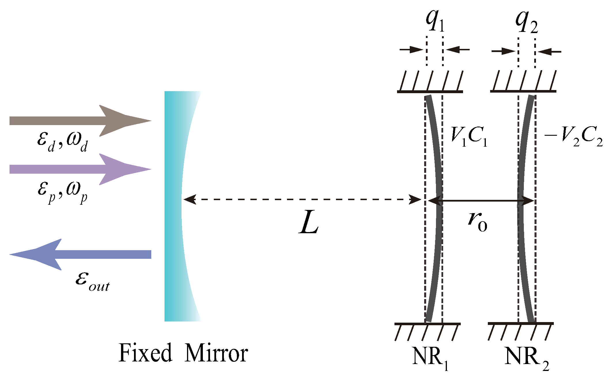
2. System and Hamiltonian

The system we consider includes a cavity and two NRs, in which the NR 1 (NR 2 ) with frequency ω 1 ( ω 2 ) is charged by the bias gate voltage V 1 ( V 2 ). The optomechanical cavity with frequency ω a (length L) is driven by a strong driving field with frequency ω d (amplitude ε d ) and a weak probe field with frequency ω p (amplitude ε p ), as depicted in Figure 1. The NR 1 not only couples with the cavity mode by the radiation pressure but also couples to the NR 2 by the tunable Coulomb interaction. The tunability of the Coulomb interaction between two charged NRs can be controlled by the bias voltages. The cavity annihilation (creation) operator is denoted by a ( a ) with the commutation relation a , a = 1 . q 1 ( q 2 ) and p 1 ( p 2 ) are the position and momentum operators of the charged NR 1 (NR 2 ) with damping rate γ 1 ( γ 2 ) and mass m 1 ( m 2 ), respectively. The driving (probe) field amplitude can be described as ε d = 2 κ P / ω d ( ε p = 2 κ P p / ω p ), where P ( P p ) is the power of the driving (probe) field, and κ is the total decay rate of the cavity. Thus, the total Hamiltonian of the system can be written as
H = H 1 + H 2 + ω a a a g a a q 1 + λ q 1 q 2 + i ε d a e i ω d t a e i ω d t + i a ε p e i ω p t a ε p * e i ω p t ,
where
H 1 = p 1 2 2 m 1 + 1 2 m 1 ω 1 2 q 1 2 , H 2 = p 2 2 2 m 2 + 1 2 m 2 ω 2 2 q 2 2 .
The first three terms represent the free Hamiltonian of the mechanical modes and cavity mode, respectively. The fourth term shows the radiation pressure interaction between the cavity mode and NR 1 with the coupling strength g = ω a / L . The fifth term describes the Coulomb interaction between the NR 1 and NR 2 with the Coulomb coupling constant λ = C 1 V 1 C 2 V 2 / ( 2 π ε 0 r 0 3 ) [51], in which V 1 ( V 2 ) and C 1 ( C 2 ) are the voltage and capacitance of the bias gate, respectively, and r 0 is the equilibrium distance between the two NRs. The sixth (last) term presents the interaction Hamiltonian between the cavity mode and the strong driving (weak probe) field. Here, we investigate the optical response of the optomechanical system to the probe output field in the presence of the driving field. In the rotating frame at the frequency of the driving field ω d , the total Hamiltonian is described as
H = H 1 + H 2 + Δ a a a g a a q 1 + λ q 1 q 2 + i ε d a a + i a ε p e i δ t a ε p * e i δ t ,
where Δ a = ω a ω d ( δ = ω p ω d ) is the detuning between the driving field and the cavity mode (probe field). By utilizing the factorization assumption q c = q c and ignoring the quantum Brownian noise term with a zero mean value in the dynamical analysis, the nonlinear quantum Langevin equations for the mean value based on Equation (3) can be written as
q 1 ˙ = p 1 m 1 , q 2 ˙ = p 2 m 2 , p 1 ˙ = m 1 ω 1 2 q 1 λ q 2 + g a a γ 1 p 1 , p 2 ˙ = m 2 ω 2 2 q 2 λ q 1 γ 2 p 2 , a ˙ = [ κ + i ( Δ a g q 1 ) ] a + ε d + ε p e i δ t ,
where κ = κ i n + κ e x t with κ i n ( κ e x t ) are the intrinsic photon (external coupling) loss [69,70]. To obtain the amplitudes of the first-order sidebands, we solve Equation (4) using the perturbation method by writing the solution in the form O ^ = O s + ε p O ^ + e i δ t + ε p * O ^ e i δ t , where O = a , q i , p i ( i = 1 , 2 ) . Then, the first-order terms can be only taken since the driving field is much stronger than the probe field. The steady-state solutions are given by
p 1 s = p 2 s = 0 , q 1 s = g | a s | 2 m 1 ω 1 2 2 λ 2 m 2 ω 2 2 , q 2 s = λ q 1 s m 2 ω 2 2 , a s = ε d i Δ + κ ,
where Δ = Δ a g q 1 s . Then, we can obtain
m 1 ( ω 1 2 i δ γ 1 δ 2 ) q 1 + + λ q 2 + = g ( a s * a + + a * a s ) , m 1 ( ω 1 2 + i δ γ 1 δ 2 ) q 1 + λ q 2 = g ( a s * a + a + * a s ) , m 2 ( ω 2 2 i δ γ 2 δ 2 ) q 2 + = λ q 1 + , m 2 ( ω 2 2 + i δ γ 2 δ 2 ) q 2 = λ q 1 , ( κ + i Δ i δ ) a + = i g q 1 + a s + 1 , ( κ + i Δ + i δ ) a = i g q 1 a s .
The coefficient of the first-order upper sideband is given by
a + = 1 κ + i ( Δ δ ) i g 2 | a s | 2 m 1 ( ω 1 2 i δ γ 1 δ 2 ) 2 λ 2 m 2 ( ω 2 2 i δ γ 2 δ 2 ) + i g 2 | a s | 2 κ i ( Δ + δ ) .
According to the input–output relation for the cavity field [71], the optical components with frequency ω p in the output field can be defined as ε T = 2 η κ a + [72], in which η = κ e x t / ( κ i n + κ e x t ) can be continuously changed in the experiment [70] and affect the optical phenomena of the system. Under the condition of a near-resonant frequency, i.e., Δ δ ω 1 , ε T can be rewritten as (see Appendix A for specific derivation)
ε T = 2 η κ κ i ( δ ω 1 ) + β i ( δ ω 1 ) + γ 1 2 + i G 2 ω 1 + N ,
here
N = β κ 2 i ω 1 , β = χ 0 2 ε d 2 2 m 1 ω 1 ( κ 2 + ω 1 2 ) , G = 2 λ 2 2 ω 2 m 1 m 2 [ ( δ ω 2 ) + i γ 2 / 2 ] ,
where χ 0 = g . The real and imaginary parts of ε T , respectively, indicate in-phase and out-of-phase output field quadratures at the probe frequency ω p , i.e., the absorption and dispersion properties of the optomechanical system. As the vital term, the counterrotating term N in Equation (9) will not exist in the sub-fraction of Equation (8) if we solve Equation (4) by using the usual RWA method. Specifically, we first use the second quantization method presented by Holstein and Primakoff to simplify the Hamiltonian of the system, then we can calculate the nonlinear quantum Langevin equations for the mean value of the system. Furthermore, the RWA method is used in the dynamic analysis of the system; that is, we can take the rotation transformation of frequencies ω 1 and Δ and omit the high-frequency oscillations terms. Finally, we can obtain the probe output field ε T , which does not include N terms. Thus, we think that the N term comes from the high-frequency oscillations terms, i.e., the counterrotating term [73]. In contrast to Ref. [51], which mainly studied the double OMIT effect caused by the Coulomb interaction between the NR 1 and NR 2 , we find that the counterrotating term gives rise to the double OMIA effect.

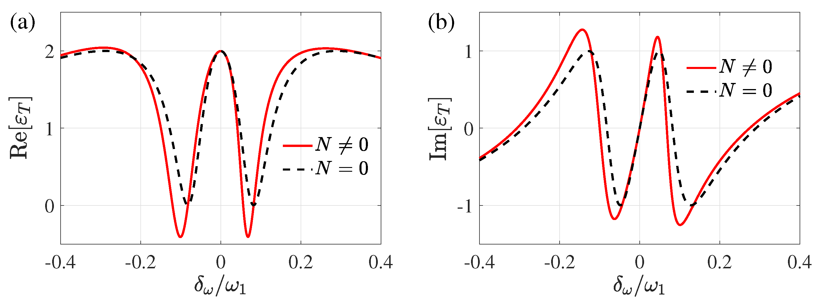
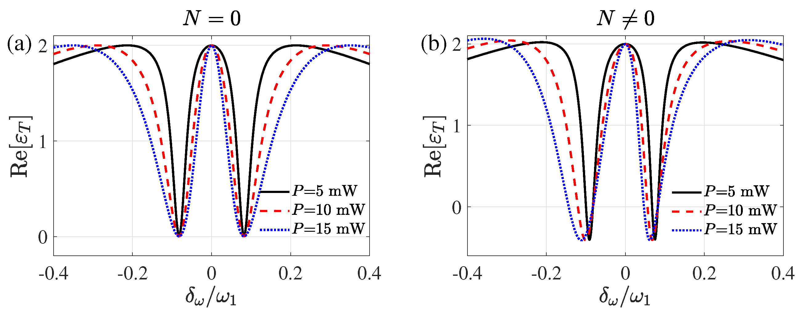
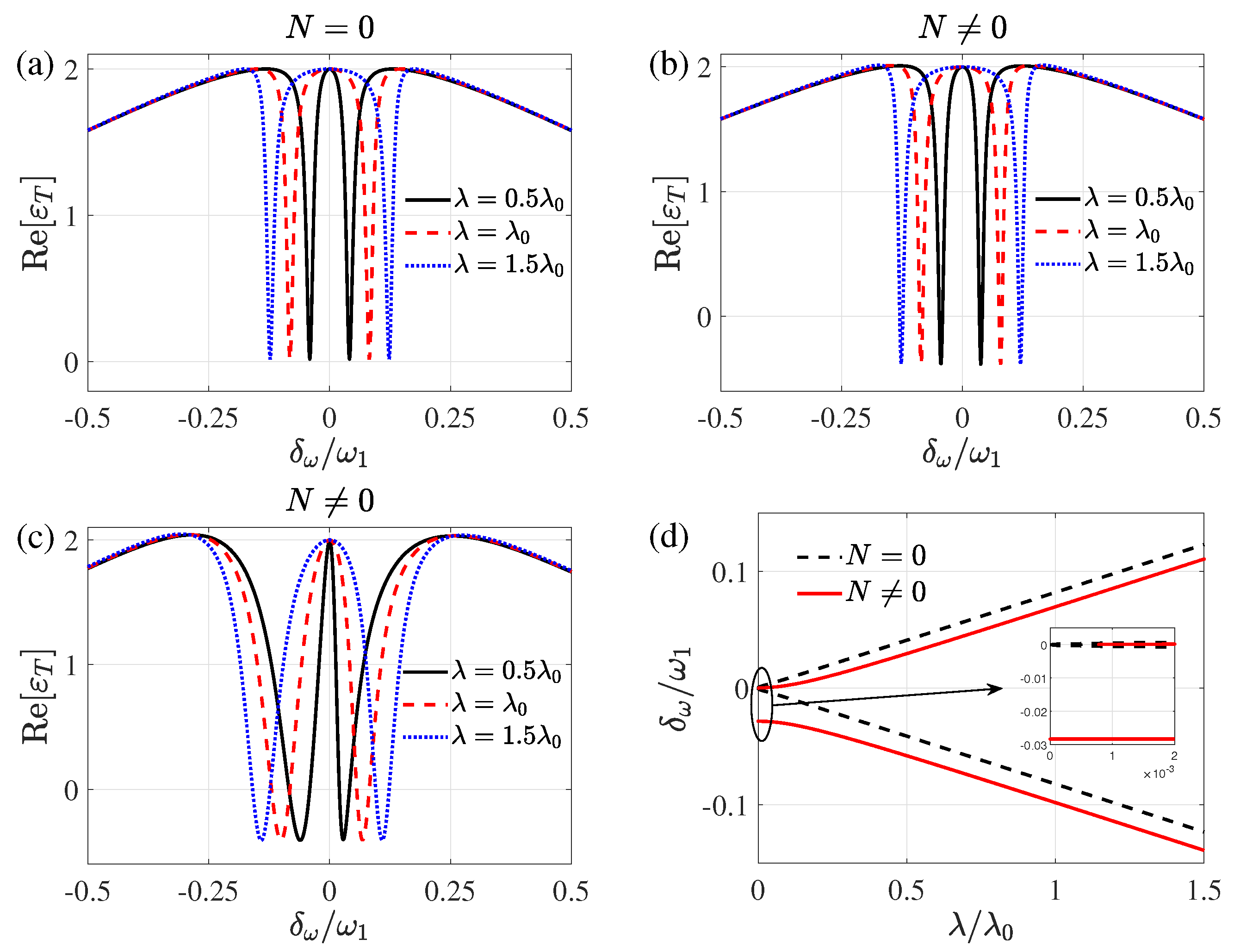
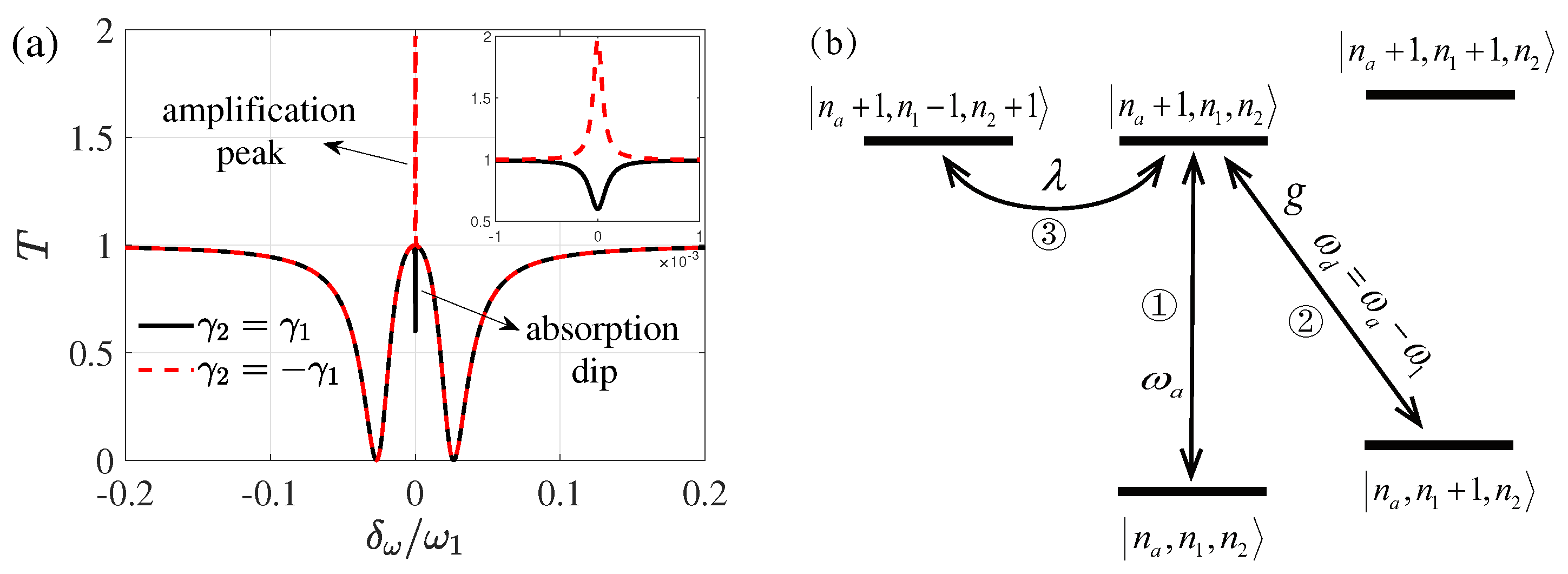
3. Influence of the Counterrotating Term

In the above section, we calculate the optical response of the present system to the probe output field and obtain the analytical solution of the output field components at the probe frequency. Now, we first investigate the influence of the counterrotating term on the optomechanical system.

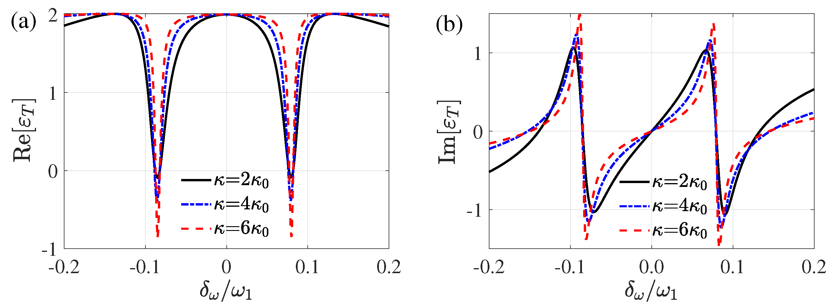
3.1. Asymmetry of Double Optomechanically Induced Amplification

The parameters selected in our work satisfy the stability condition of the Routh–Hurwitz criterion (please see Appendix B). In Figure 2, the absorption property Re[ ε T ] and the dispersion property Im[ ε T ] of the probe output field are plotted as functions of the normalized frequency δ ω / ω 1 with the detuning δ ω = δ ω 1 . There are two transparency dips because of the Coulomb coupling between the two NRs, as shown in Figure 2a. The line shapes of the two transparency dips are symmetric about the resonance δ ω / ω 1 = 0 when the counterrotating term is ignored in the dynamical analysis of the system, i.e., N = 0 . Furthermore, the ideal double OMIT effect appears because the minimum values of the two transparency dips equal to zero. However, the line shapes of the two transparency dips are asymmetric about the resonance when the counterrotating term is considered in the dynamical analysis of the system, i.e., N 0 . The minimum values of the two transparency dips are less than zero, which results in the emergence of the asymmetric double OMIA effect. Compared with N = 0 , the positions of the two transparency dips slightly shift to left and the width of the left transparency dip is larger than the right one. Thus, utilizing the counterrotating term, (i) the double OMIA effect can be found, and (ii) the asymmetry of two transparency dips can also be obtained. As illustrated in Figure 2b, when N = 0 , the two steepest dispersion curves with the same negative slopes correspond to the two transparency dips in Figure 2a, so the probe field has the same fast phase dispersion changes in the two transparency dips. When N 0 , there are two steeper dispersion curves with different negative slopes corresponding to the two transparency dips in Figure 2a. The steepest dispersion curve on the right is steeper than that on the left, indicating that the probe field experiences a faster phase dispersion change in the right transparency dip. Compared to N = 0 , the steepest curves slightly shift to the left and the negative slopes of the steepest curves become larger, which means that the existence of the counterrotating term makes the probe field undergo different fast phase dispersion changes in the two transparency dips.
The decay rate of the optical cavity is a very important parameter in the system and affects the phenomenon of the double OMIT. Figure 3 shows the absorption property Re[ ε T ] and dispersion property Im[ ε T ] as functions of the normalized frequency δ ω / ω 1 for the different cavity decay rates κ . With the increase of the cavity decay rate κ , the minimal values of the two transparency dips increase when the counterrotating term is ignored in the dynamical analysis. However, as shown in Figure 3a, the two transparency dips become narrow, and the minimal values of the dips decrease with the increase of the cavity decay rate κ . It is demonstrated that the double OMIA effect of the probe output field is enhanced when the cavity decay rate κ increases. In Figure 3b, the dispersion curves corresponding to the positions of the two transparency dips at δ ω / ω 1 ± 0.085 of Figure 3a become sharp, and the negative values of the dispersion curves slope increase with the increase of decay rate κ . However, the dispersion curve changes dramatically at resonance, where the part with a positive slope becomes smaller quickly.
The effective radiation pressure coupling between cavity mode and NR 1 plays an important role in the system. As shown in Figure 4, we plot the absorption property Re[ ε T ] of the probe output field as a function of the normalized frequency δ ω / ω 1 for different powers P of the driving field. The two transparency dips of double OMIT symmetrically change for the growing effective radiation pressure coupling of the system in the absence of the counterrotating term in Figure 4a, where the positions of the two transparency dips remain unchanged and the widths of the two transparency dips symmetrically become wider. However, the symmetry is broken when the counterrotating term is taken into account. As described in Figure 4b, the widths and positions of the two transparency dips asymmetrically change in the presence of the counterrotating term. With the increase of the driving field power P, the widths of the two transparency dips become wider asymmetrically and the positions of the two transparency dips move to the left, in which the width of the left transparency dip is notably larger than that of the right dip, and the distance of the left dip from the resonance is observably greater than that of the right one. It means that the large driving field power P enhances the asymmetry of the two transparency dips. The physical mechanism is that the strong effective radiation pressure coupling induces the enhancement of the counterrotating term, which leads to the increase of the asymmetry degree of two transparency dips.
To further investigate the property of the double OMIA and the asymmetry of the two transparency dips, we consider the influence of the Coulomb coupling strength on the probe output field. In Figure 5a–c, we plot the absorption property Re[ ε T ] of the probe output field as a function of the normalized frequency δ ω / ω 1 for different Coulomb coupling strengths λ , which can be tuned by the bias voltages of the two NRs. Figure 5a shows that the two transparency dips symmetrically change, and the distance between the two transparency dips becomes larger with the increase of the Coulomb coupling strength λ when the counterrotating term is ignored. Taking the counterrotating term into account, in Figure 5b, we not only find the double OMIA effect but also find that two transparency dips change symmetrically with the Coulomb coupling strength λ . In the above, we have shown that the asymmetry of the transparency windows could be enhanced by the effective radiation pressure coupling strength. Now, we further study the asymmetry of the two transparency dips for P = 10 mW in Figure 5c. Compared with Figure 5b, it can be clearly seen that the two transparency dips have obvious asymmetry in the probe output field under the weak Coulomb coupling strength λ . In Figure 5d, we plot the positions of the two transparency dips as functions of the Coulomb coupling strength λ . The red solid lines represent the positions of the two transparency dips in Figure 5c when the counterrotating term is considered, and the distance between the two transparency dips is described by the difference value between the vertical coordinates of the lines. The black dashed lines represent the positions of the two transparency dips when the counterrotating term is ignored. As can be clearly seen, the red solid lines are always below the black dashed lines, which further proves the shift of two transparency dips in Figure 2a. It is worth noting that the red solid lines are discontinuous at λ 0.001 λ 0 due to the shift of the transparency dip caused by the counterrotating term and the split of transparency dip caused by the Coulomb coupling at resonance.

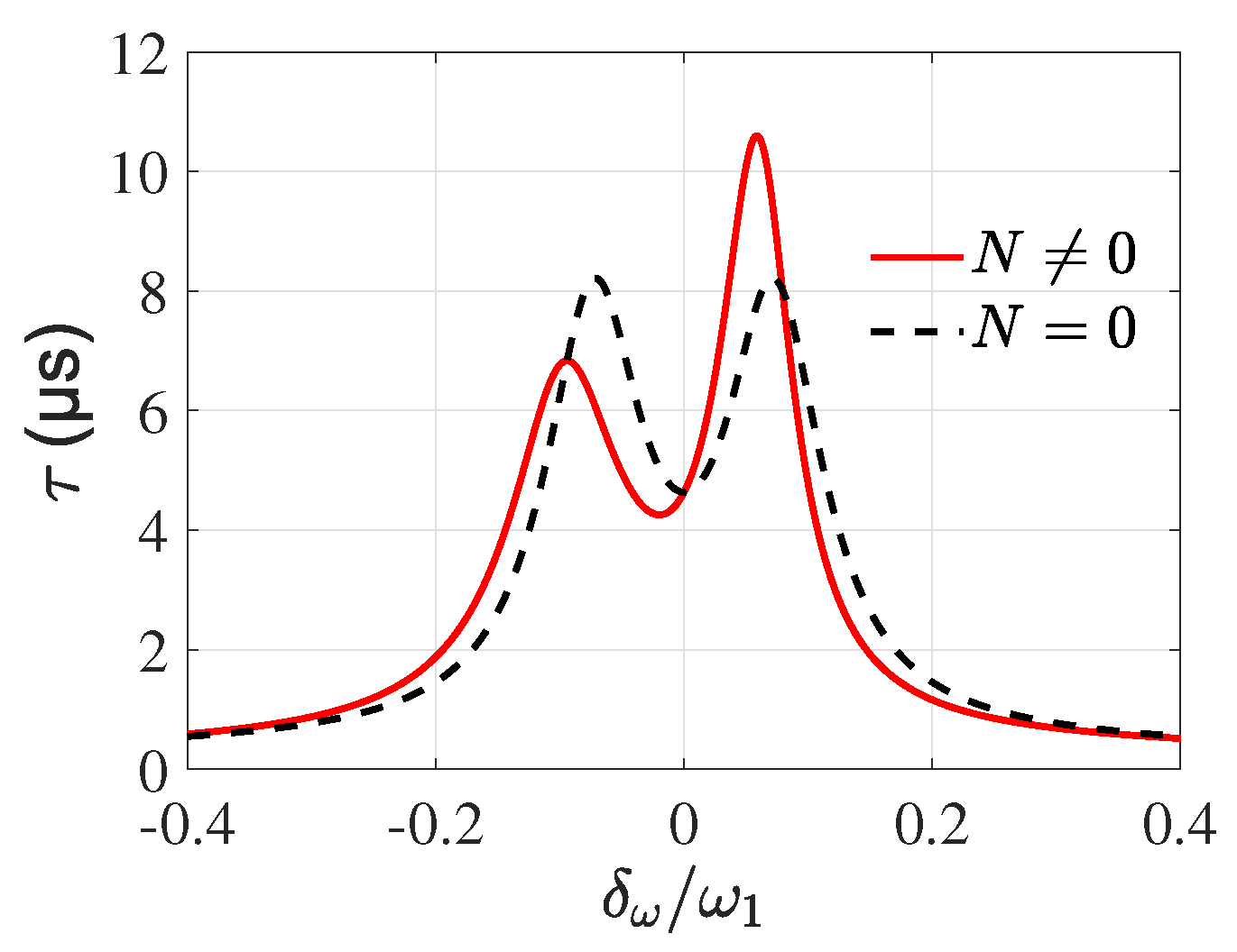
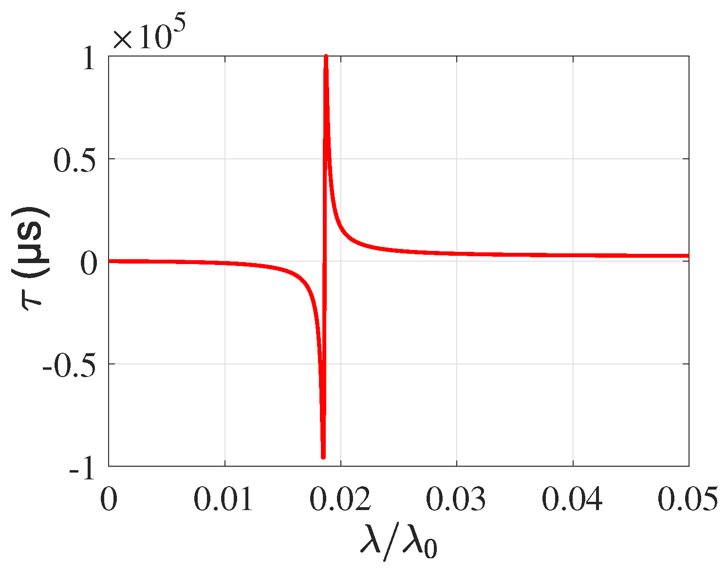
3.2. Fast-Slow Light Effect

Similar to the OMIT and OMIA effects, the fast-slow light effect is an important optical phenomenon that can be realized in the cavity optomechanical system and has been widely studied [60,61,62]. As is well known, the probe field in an EIT window usually experiences a fast phase dispersion, which leads to a dramatic reduction in the group velocity. It also occurs for the transmission of light through the OMIT window in the cavity optomechanical system. We now discuss the influence of the counterrotating term on the group delay of the probe output field. According to Equation (7), the transmission rate corresponding to the probe output field can be expressed as [75]
T = t p 2 = 1 2 η κ a + 2 .
The optical group delay of the transmitted light is defined as [62]
τ = d ϕ ( ω p ) d ω p = d arg [ t p ( δ ) ] d δ ω = Im 1 t p t p δ ω ,
where ϕ ( ω p ) = arg [ t p ( δ ) ] is the phase of the probe output field. τ > 0 represents the slow light propagations, and τ < 0 represents the fast light propagations.
In Figure 6, we plot the optical group delay time of the probe output field as a function of the normalized frequency δ ω / ω 1 . It indicates the appearance of the slow light effect caused by the radiation pressure coupling and Coulomb coupling. For N = 0 , the group delay curve is symmetric, and in the two transparency dips δ ω / ω 1 ± 0.085 , there is the same group delay time τ . While for N 0 , the group delay curve is asymmetric, and the group delay time τ of the right transparency dip is significantly larger than the left one. That is because the probe field experiences faster phase dispersion in the right transparency dip, as in Figure 2b. This further proves that the counterrotating term affects the fast phase dispersion of the probe field inside the two transparency dips.

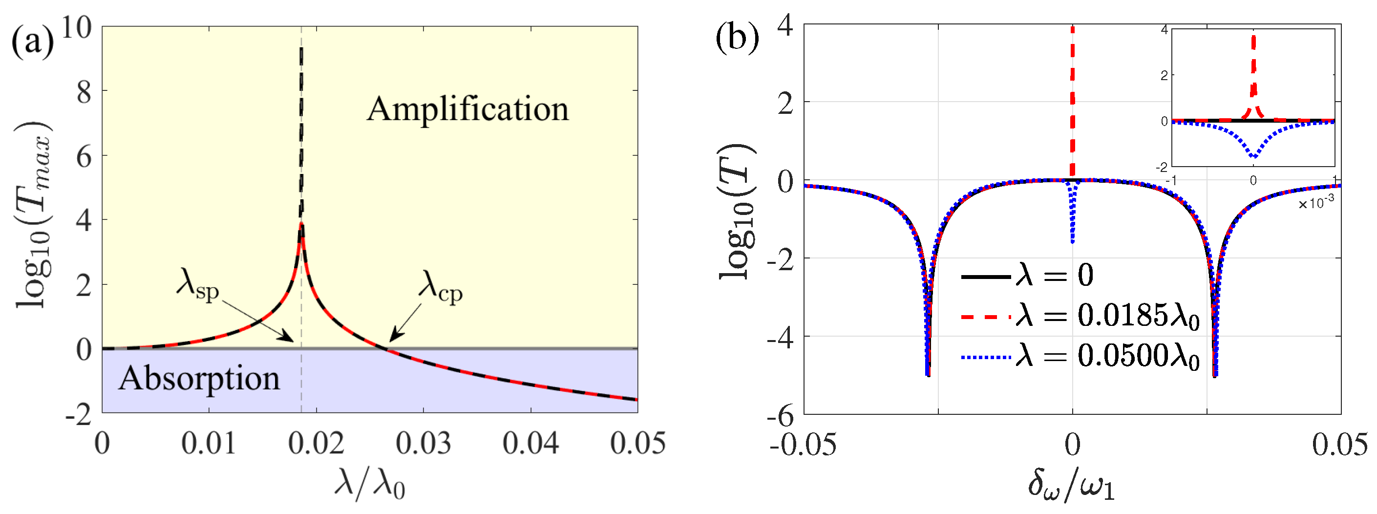
4. Application of the Counterrotating Term to the System with Mechanical Gain

Since the coherent manipulation of phonons, such as phonon laser and phonon pump, can introduce a considerable gain to mechanical resonators, the optomechanical system with mechanical gain has attracted a lot of attention and has been studied extensively in recent years, for instance, controllable optical response [59], optomechanical transistor [76], etc. In this section, we consider the NR 2 with gain to study the influence of mechanical gain on the probe output field. According to the foregoing parameters, we set the gain rate of NR 2 as γ 2 = γ 1 = ω 1 / 6700 and find an interesting phenomenon when the optical cavity has a small decay rate. Different optical responses will occur for different Coulomb coupling strengths between the two NRs. The significant optical amplification effect can be observed and the transmission rate of the probe output field can reach about 10 4 orders of magnitude.
We first study the transmission rate of the probe output field for η = 1 / 2 [75]. Figure 7a shows the transmission rate T of the output field as a function of the normalized frequency δ ω / ω 1 when the Coulomb coupling strength is chosen as λ = 0.01 λ 0 . When γ 2 = γ 1 , there are two sideband dips and an absorption dip in the spectrum. Due to the normal-mode splitting effect between two NRs caused by the Coulomb coupling, an absorption dip appears in the transparency peak caused by the optomechanical interaction at the resonance, i.e., the optical absorption effect occurs. The physical mechanism of this process is shown in Figure 7b, whose reason is that the destructive interference between the transition paths 1 and 2 leads to the OMIT effect. With the emergence of the Coulomb coupling, the constructive interference between transition paths 1 and 3 enhances the absorption capacity of the system to the photons of the probe field. As a result, an absorption dip appears at the resonance in Figure 7a. However, the absorption dip is transformed into an amplification peak when we consider the gain NR 2 , i.e., γ 2 = γ 1 , meaning the appearance of the remarkable optical amplification effect. Therefore, the optical response of the present system to the probe output field changes from the optical absorption effect to the remarkable optical amplification effect due to the mechanical gain.
Next, we investigate the influence of Coulomb coupling strength on the probe output field. In Figure 8a, the transmission rate T m a x at resonance is plotted as a function of the Coulomb coupling strength λ when the N term exists or not. One can see that the transmission rate curve increases first and then decreases with the increase of λ , and finally, it is gradually less than 1. There exists a maximum value of the order of 10 4 at the singular point λ sp 0.0185 λ 0 for N 0 (red solid line), i.e., the excellent optical amplification effect appears. In particular, there is a critical point λ cp 0.0262 λ 0 between the optical amplification and absorption. We can observe that the transmission rate is greater than 1 at λ < λ cp , which manifests the emergence of the optical amplification effect. In addition, the optical amplification effect can be changed into the optical absorption effect for the strong Coulomb coupling when λ > λ cp . Therefore, the conversion between the optical amplification and the absorption effects can be easily achieved by adjusting the Coulomb coupling strength based on mechanical gain. It is worth noting that the peak values of the black dashed line ( N = 0 ) and red solid line ( N 0 ) both appear at the singular point λ sp , and the maximum value of the black dashed line is greater than that of the red solid line, which means that the optical amplification effect of the system without the N term is better than that in the presence of the N term. The reason is that due to the introduction of the N term, the optical amplification effect of the system is revised to the effect that can be achieved in practice. In Figure 8b, we show the transmission rate T as a function of the normalized frequency δ ω / ω 1 for different Coulomb coupling strengths. Consistent with Figure 8a, there is a significant optical amplification effect at resonance and the maximum value of the transmission rate T approaches to the order of 10 4 at the singular point λ = 0.0185 λ 0 . However, the transmission rate T becomes less than 1 at resonance in the transmission spectrum for λ = 0.05 λ 0 , which indicates that the optical amplification effect is transformed into the optical absorption effect. This further proves that the different optical responses can be easily achieved by adjusting the Coulomb coupling strength properly.
Finally, we study the fast-slow light effect of the system with mechanical gain. In Figure 9, we show the group delay time τ of the probe output field at resonance as a function of the Coulomb coupling strength. One can see that the group delay time can easily reach the order of 10 5 μ s , which leads to the prominent fast-slow light effect. The physical reason is that the mechanical gain causes a sharp change in the phase dispersion of the probe field in the transparency window. What is noteworthy is that the prominent group delay is always near the singular point λ sp , at which the fast light can be easily converted to the slow light. Therefore, the prominent fast-slow light effect resorting to mechanical gain can be observed at the singular point.

5. Conclusions

In conclusion, we have investigated the optical responses of the three-mode cavity optomechanical system without the RWA method and discussed two ways of achieving the optical amplification effect. The asymmetric double OMIA effect can be observed with the counterrotating term, and the optical amplification effect is enhanced with the increase of the cavity decay rate and the optomechanical interaction. The strong effective radiation pressure coupling induces the enhancement of the counterrotating term, leading to the more obvious asymmetry of two transparency dips. Besides, the counterrotating term affects the fast phase dispersion and the group delay time of the probe field inside the two transparency dips. Furthermore, we discover the emergency of the excellent optical amplification effect with mechanical gain and the transmission rate of the output field can reach the order of 10 4 . There is a critical point λ cp between the optical amplification and the absorption effects, and different optical responses can be easily achieved by adjusting the Coulomb coupling strength properly. It is worth noting that the prominent fast-slow light effect based on mechanical gain can be observed at the singular point, and the prominent group delay time can easily approach to the order of 10 5 μ s . Our scheme may open up new avenues of steering the potential applications in quantum information processing and quantum precision measurement.

Author Contributions

Conceptualization, Y.-N.Z. and T.W.; methodology, Y.-N.Z. and T.W.; software, Y.-N.Z. and T.W.; validation, D.-Y.W., X.H. and H.-F.W.; formal analysis, Y.-N.Z.; investigation, Y.-N.Z.; resources, X.H., H.-F.W. and S.Z.; data curation, X.H., H.-F.W. and S.Z.; writing—original draft preparation, Y.-N.Z.; writing—review and editing, T.W., D.-Y.W., X.H. and H.-F.W. All authors have read and agreed to the published version of the manuscript.

Funding

This research was funded by the National Natural Science Foundation of China under Grants No. 61822114, No. 12074330, No. 62071412.

Institutional Review Board Statement

Not applicable.

Informed Consent Statement

Not applicable.

Data Availability Statement

Not applicable.

Conflicts of Interest

The authors declare no conflict of interest.

Appendix A. Derivation of the Probe Output Field

Here we explain the derivation of the probe output field ε T in detail. From Equation (6), we can directly obtain
q 1 + = g ( a s * a + + a * a s ) m 1 ( ω 1 2 i δ γ 1 δ 2 ) 2 λ 2 m 2 ( ω 2 2 i δ γ 2 δ 2 ) ,
q 1 = g ( a s * a + a + * a s ) m 1 ( ω 1 2 + i δ γ 1 δ 2 ) 2 λ 2 m 2 ( ω 2 2 + i δ γ 2 δ 2 ) ,
q 2 + = λ m 2 ( ω 2 2 i δ γ 2 δ 2 ) q 1 + ,
q 2 = λ m 2 ( ω 2 2 + i δ γ 2 δ 2 ) q 1 ,
a + = i g a s q 1 + + 1 κ + i ( Δ δ ) ,
a = i g a s q 1 κ + i ( Δ + δ ) ,
where q 1 + = q 1 * and q 2 + = q 2 * . According to Equations (A1) and (A5), considering a s as a whole, it can be easily obtained
a * a s = A 1 A a s * a + ,
here
A = i g 2 | a s | 2 [ κ i ( Δ + δ ) ] [ m 1 ( ω 1 2 i δ γ 1 δ 2 ) 2 λ 2 m 2 ( ω 2 2 i δ γ 2 δ 2 ) ] .
Equation (A7) is the key step. By substituting Equation (A7) into Equation (A1), we get an expression of q + as
q + = g [ κ i ( Δ + δ ) ] a s * a + [ κ i ( Δ + δ ) ] [ m 1 ( ω 1 2 i δ γ 1 δ 2 ) 2 λ 2 m 2 ( ω 2 2 i δ γ 2 δ 2 ) ] + i g 2 | a s | 2 .
Then, according to Equation (A5), we get an expression of a + as
a + = 1 κ + i ( Δ δ ) i g 2 | a s | 2 m 1 ( ω 1 2 i δ γ 1 δ 2 ) 2 λ 2 m 2 ( ω 2 2 i δ γ 2 δ 2 ) + i g 2 | a s | 2 κ i ( Δ + δ ) .
Under the condition of near-resonant frequency, i.e., Δ δ ω 1 , we have δ 2 ω 1 2 2 ω 1 ( δ ω 1 ) and δ + Δ 2 ω 1 . According to the input–output relation for the cavity field [71], the optical components with frequency ω p in the output field can be defined as ε T = 2 η κ a + with η = κ e x t / ( κ i n + κ e x t ) . ε T can be rewritten as Equations (8) and (9)
ε T = 2 η κ κ i ( δ ω 1 ) + β i ( δ ω 1 ) + γ 1 2 + i G 2 ω 1 + N ,
here
N = β κ 2 i ω 1 , β = χ 0 2 ε d 2 2 m 1 ω 1 ( κ 2 + ω 1 2 ) , G = 2 λ 2 2 ω 2 m 1 m 2 [ ( δ ω 2 ) + i γ 2 / 2 ] .

Appendix B. Stability Analysis of the Three-Mode Cavity Optomechanical System

Here, we specifically analyze the stability of the three-mode cavity optomechanical system. From Equation (4), by writing the solution in the form S = S s + δ S with S = a , q i , p i ( i = 1 , 2 ) , we can rewrite the nonlinear quantum Langevin equations for the fluctuations as
δ q 1 ˙ = δ p 1 m 1 , δ q 2 ˙ = δ p 2 m 2 , δ p 1 ˙ = m 1 ω 1 2 δ q 1 λ δ q 2 + g δ a δ a γ 1 δ p 1 , δ p 2 ˙ = m 2 ω 2 2 δ q 2 λ δ q 1 γ 2 δ p 2 , δ a ˙ = ( κ + i Δ ) δ a ,
then, we introduce the quadrature operators δ X = ( δ a + δ a ) / 2 and δ Y = i ( δ a δ a ) / 2 . We can rewrite the quantum Langevin equations for the fluctuations in a matrix form as
U ˙ ( t ) = A U ( t ) ,
where U ( t ) = [ δ X , δ Y , δ q 1 , δ p 1 , δ q 2 , δ p 2 ] T , and the drift matrix
A = κ Δ 0 0 0 0 Δ κ 0 0 0 0 0 0 0 1 m 1 0 0 g a s 0 m 1 ω 1 2 γ 1 λ 0 0 0 0 0 0 1 m 2 0 0 λ 0 m 2 ω 2 2 γ 2
By numerical calculation, we find that the eigenvalues of all the coefficients of the matrix A have negative real parts. According to the Routh–Hurwitz criterion, the three-mode cavity optomechanical system we consider is stable.
In order to further analyze the bistability of the three-mode cavity optomechanical system, the steady-state mean value of the cavity mode a s is plotted with the power of the driving field P in Figure A1. The steady-state average value of the cavity mode increases monotonously with the driving power, so the three-mode cavity optomechanical system is monostable.
Figure A1. The steady-state mean value of the cavity mode a s is plotted with the power of the driving field P. The other parameters are the same as given in Figure 2.
Photonics 08 00384 g0a1

References

  1. Bowen, W.P.; Milburn, G.J. Quantum Optomechanics; Taylor & Francis Group: Boca Raton, FL, USA, 2015. [Google Scholar]
  2. Brandes, T. Feedback Control of Quantum Transport. Phys. Rev. Lett. 2010, 105, 060602. [Google Scholar] [CrossRef] [Green Version]
  3. Grimsmo, A.L. Time-Delayed Quantum Feedback Control. Phys. Rev. Lett. 2015, 115, 060402. [Google Scholar] [CrossRef] [Green Version]
  4. Nunnenkamp, A.; Børkje, K.; Girvin, S.M. Single-Photon Optomechanics. Phys. Rev. Lett. 2011, 107, 063602. [Google Scholar] [CrossRef] [PubMed] [Green Version]
  5. Leijssen, R.; La Gala, G.R.; Freisem, L.; Muhonen, J.T.; Verhagen, E. Nonlinear cavity optomechanics with nanomechanical thermal fluctuations. Nat. Commun. 2017, 8, ncomms16024. [Google Scholar] [CrossRef] [Green Version]
  6. Pang, B.; Chen, Y.B. Fundamental relations between measurement, radiation, and decoherence in gravitational wave laser interferometer detectors. Phys. Rev. D 2019, 99, 124016. [Google Scholar] [CrossRef] [Green Version]
  7. Verlot, P.; Tavernarakis, A.; Briant, T.; Cohadon, P.F.; Heidmann, A. Backaction Amplification and Quantum Limits in Optomechanical Measurements. Phys. Rev. Lett. 2010, 104, 133602. [Google Scholar] [CrossRef] [PubMed] [Green Version]
  8. Braunstein, S.L. Quantum limits on precision measurements of phase. Phys. Rev. Lett. 1992, 69, 3598–3601. [Google Scholar] [CrossRef]
  9. Kippenberg, T.J.; Vahala, K.J. Cavity Optomechanics: Back-Action at the Mesoscale. Science 2008, 321, 1172–1176. [Google Scholar] [CrossRef] [Green Version]
  10. Mahajan, S.; Kumar, T.; Bhattacherjee, A.B.; ManMohan. Ground-state cooling of a mechanical oscillator and detection of a weak force using a Bose-Einstein condensate. Phys. Rev. A 2013, 87, 013621. [Google Scholar] [CrossRef]
  11. Bai, C.H.; Wang, D.Y.; Zhang, S.; Wang, H.F. Qubit-assisted squeezing of mirror motion in a dissipative cavity optomechanical system. Sci. China Phys. Mech. Astron. 2019, 62, 970311. [Google Scholar] [CrossRef]
  12. Lü, X.Y.; Liao, J.Q.; Tian, L.; Nori, F. Steady-state mechanical squeezing in an optomechanical system via Duffing nonlinearity. Phys. Rev. A 2015, 91, 013834. [Google Scholar] [CrossRef] [Green Version]
  13. Agarwal, G.S.; Huang, S.M. Strong mechanical squeezing and its detection. Phys. Rev. A 2016, 93, 043844. [Google Scholar] [CrossRef] [Green Version]
  14. Wang, D.Y.; Bai, C.H.; Wang, H.F.; Zhu, A.D.; Zhang, S. Steady-state mechanical squeezing in a hybrid atom-optomechanical system with a highly dissipative cavity. Sci. Rep. 2016, 6, 2045–2322. [Google Scholar] [CrossRef] [Green Version]
  15. Bai, C.H.; Wang, D.Y.; Zhang, S.; Liu, S.; Wang, H.F. Engineering of strong mechanical squeezing via the joint effect between Duffing nonlinearity and parametric pump driving. Photon. Res. 2019, 7, 1229–1239. [Google Scholar] [CrossRef]
  16. Arcizet, O.; Cohadon, P.F.; Briant, T.; Pinard, M.; Heidmann, A. Radiation-pressure cooling and optomechanical instability of a micromirror. Nature 2006, 444, 71–74. [Google Scholar] [CrossRef] [Green Version]
  17. Liu, Y.C.; Xiao, Y.F.; Luan, X.S.; Wong, C.W. Dynamic Dissipative Cooling of a Mechanical Resonator in Strong Coupling Optomechanics. Phys. Rev. Lett. 2013, 110, 153606. [Google Scholar] [CrossRef] [Green Version]
  18. Yang, Z.X.; Wang, L.; Liu, Y.M.; Wang, D.Y.; Bai, C.H.; Zhang, S.; Wang, H.F. Ground state cooling of magnomechanical resonator in PT-symmetric cavity magnomechanical system at room temperature. Front. Phys. 2020, 15, 52504. [Google Scholar] [CrossRef]
  19. Marquardt, F.; Chen, J.P.; Clerk, A.A.; Girvin, S.M. Quantum Theory of Cavity-Assisted Sideband Cooling of Mechanical Motion. Phys. Rev. Lett. 2007, 99, 093902. [Google Scholar] [CrossRef] [Green Version]
  20. Wang, H.; Gu, X.; Liu, Y.X.; Miranowicz, A.; Nori, F. Tunable photon blockade in a hybrid system consisting of an optomechanical device coupled to a two-level system. Phys. Rev. A 2015, 92, 033806. [Google Scholar] [CrossRef] [Green Version]
  21. Qiu, L.; Gan, L.; Ding, W.; Li, Z.Y. Single-photon generation by pulsed laser in optomechanical system via photon blockade effect. J. Opt. Soc. Am. B 2013, 30, 1683–1687. [Google Scholar] [CrossRef]
  22. Wang, D.Y.; Bai, C.H.; Xing, Y.; Liu, S.; Zhang, S.; Wang, H.F. Enhanced photon blockade via driving a trapped Λ-type atom in a hybrid optomechanical system. Phys. Rev. A 2020, 102, 043705. [Google Scholar] [CrossRef]
  23. Hartmann, M.J.; Plenio, M.B. Steady State Entanglement in the Mechanical Vibrations of Two Dielectric Membranes. Phys. Rev. Lett. 2008, 101, 200503. [Google Scholar] [CrossRef] [PubMed] [Green Version]
  24. Mari, A.; Eisert, J. Gently Modulating Optomechanical Systems. Phys. Rev. Lett. 2009, 103, 213603. [Google Scholar] [CrossRef] [Green Version]
  25. Chen, R.X.; Shen, L.T.; Yang, Z.B.; Wu, H.Z.; Zheng, S.B. Enhancement of entanglement in distant mechanical vibrations via modulation in a coupled optomechanical system. Phys. Rev. A 2014, 89, 023843. [Google Scholar] [CrossRef]
  26. Bai, C.H.; Wang, D.Y.; Wang, H.F.; Zhu, A.D.; Zhang, S. Robust entanglement between a movable mirror and atomic ensemble and entanglement transfer in coupled optomechanical system. Sci. Rep. 2016, 6, 33404. [Google Scholar] [CrossRef] [PubMed] [Green Version]
  27. Dobrindt, J.M.; Wilson Rae, I.; Kippenberg, T.J. Parametric Normal-Mode Splitting in Cavity Optomechanics. Phys. Rev. Lett. 2008, 101, 263602. [Google Scholar] [CrossRef] [PubMed] [Green Version]
  28. Huang, S.M.; Agarwal, G.S. Normal-mode splitting in a coupled system of a nanomechanical oscillator and a parametric amplifier cavity. Phys. Rev. A 2009, 80, 033807. [Google Scholar] [CrossRef] [Green Version]
  29. He, B.; Yang, L.; Jiang, X.S.; Xiao, M. Transmission Nonreciprocity in a Mutually Coupled Circulating Structure. Phys. Rev. Lett. 2018, 120, 203904. [Google Scholar] [CrossRef] [PubMed] [Green Version]
  30. Xu, X.W.; Li, Y. Optical nonreciprocity and optomechanical circulator in three-mode optomechanical systems. Phys. Rev. A 2015, 91, 053854. [Google Scholar] [CrossRef] [Green Version]
  31. Shahidani, S.; Naderi, M.H.; Soltanolkotabi, M. Control and manipulation of electromagnetically induced transparency in a nonlinear optomechanical system with two movable mirrors. Phys. Rev. A 2013, 88, 053813. [Google Scholar] [CrossRef] [Green Version]
  32. Liu, Y.X.; Davanço, M.; Aksyuk, V.; Srinivasan, K. Electromagnetically Induced Transparency and Wideband Wavelength Conversion in Silicon Nitride Microdisk Optomechanical Resonators. Phys. Rev. Lett. 2013, 110, 223603. [Google Scholar] [CrossRef] [PubMed] [Green Version]
  33. Jia, W.Z.; Wei, L.F.; Li, Y.; Liu, Y.X. Phase-dependent optical response properties in an optomechanical system by coherently driving the mechanical resonator. Phys. Rev. A 2015, 91, 043843. [Google Scholar] [CrossRef] [Green Version]
  34. Yan, X.B.; Cui, C.L.; Gu, K.H.; Tian, X.D.; Fu, C.B.; Wu, J.H. Coherent perfect absorption, transmission, and synthesis in a double-cavity optomechanical system. Opt. Express 2014, 22, 4886–4895. [Google Scholar] [CrossRef] [PubMed]
  35. Zhang, X.Y.; Zhou, Y.H.; Guo, Y.Q.; Yi, X.X. Optomechanically induced transparency in optomechanics with both linear and quadratic coupling. Phys. Rev. A 2018, 98, 053802. [Google Scholar] [CrossRef]
  36. Zhang, H.; Saif, F.; Jiao, Y.; Jing, H. Loss-induced transparency in optomechanics. Opt. Express 2018, 26, 25199–25210. [Google Scholar] [CrossRef] [PubMed] [Green Version]
  37. Ullah, K.; Naseem, M.T.; Müstecaplıoğlu, O.E. Tunable multiwindow magnomechanically induced transparency, Fano resonances, and slow-to-fast light conversion. Phys. Rev. A 2020, 102, 033721. [Google Scholar] [CrossRef]
  38. Chen, B.; Jiang, C.; Zhu, K.D. Slow light in a cavity optomechanical system with a Bose-Einstein condensate. Phys. Rev. A 2011, 83, 055803. [Google Scholar] [CrossRef]
  39. Si, L.G.; Xiong, H.; Zubairy, M.S.; Wu, Y. Optomechanically induced opacity and amplification in a quadratically coupled optomechanical system. Phys. Rev. A 2017, 95, 033803. [Google Scholar] [CrossRef]
  40. Hao, H.; Kuzyk, M.C.; Ren, J.J.; Zhang, F.; Duan, X.K.; Zhou, L.; Zhang, T.C.; Gong, Q.H.; Wang, H.L.; Gu, Y. Electromagnetically and optomechanically induced transparency and amplification in an atom-assisted cavity optomechanical system. Phys. Rev. A 2019, 100, 023820. [Google Scholar] [CrossRef]
  41. Nunnenkamp, A.; Sudhir, V.; Feofanov, A.K.; Roulet, A.; Kippenberg, T.J. Quantum-Limited Amplification and Parametric Instability in the Reversed Dissipation Regime of Cavity Optomechanics. Phys. Rev. Lett. 2014, 113, 023604. [Google Scholar] [CrossRef] [PubMed] [Green Version]
  42. Massel, F.; Heikkilä, T.T.; Pirkkalainen, J.M.; Cho, S.U.; Saloniemi, H.; Hakonen, P.J.; Sillanpää, M.A. Microwave amplification with nanomechanical resonators. Nature 2011, 480, 351–354. [Google Scholar] [CrossRef] [Green Version]
  43. He, Y. Optomechanically induced transparency associated with steady-state entanglement. Phys. Rev. A 2015, 91, 013827. [Google Scholar] [CrossRef]
  44. Kronwald, A.; Marquardt, F. Optomechanically Induced Transparency in the Nonlinear Quantum Regime. Phys. Rev. Lett. 2013, 111, 133601. [Google Scholar] [CrossRef] [Green Version]
  45. Hou, B.P.; Wei, L.F.; Wang, S.J. Optomechanically induced transparency and absorption in hybridized optomechanical systems. Phys. Rev. A 2015, 92, 033829. [Google Scholar] [CrossRef]
  46. Teufel, J.D.; Li, D.; Allman, M.S.; Cicak, K.; Sirois, A.J.; Whittaker, J.D.; Simmonds, R.W. Circuit cavity electromechanics in the strong-coupling regime. Nature 2011, 471, 204–208. [Google Scholar] [CrossRef] [PubMed] [Green Version]
  47. Lü, H.; Wang, C.Q.; Yang, L.; Jing, H. Optomechanically Induced Transparency at Exceptional Points. Phys. Rev. Appl. 2018, 10, 014006. [Google Scholar] [CrossRef] [Green Version]
  48. Boller, K.J.; Imamoğlu, A.; Harris, S.E. Observation of electromagnetically induced transparency. Phys. Rev. Lett. 1991, 66, 2593–2596. [Google Scholar] [CrossRef] [Green Version]
  49. Wu, Y.; Yang, X.X. Electromagnetically induced transparency in V-, Λ-, and cascade-type schemes beyond steady-state analysis. Phys. Rev. A 2005, 71, 053806. [Google Scholar] [CrossRef]
  50. Harris, S.E. Electromagnetically Induced Transparency in an Ideal Plasma. Phys. Rev. Lett. 1996, 77, 5357–5360. [Google Scholar] [CrossRef] [Green Version]
  51. Ma, P.C.; Zhang, J.Q.; Xiao, Y.; Feng, M.; Zhang, Z.M. Tunable double optomechanically induced transparency in an optomechanical system. Phys. Rev. A 2014, 90, 043825. [Google Scholar] [CrossRef] [Green Version]
  52. Wu, S.C.; Qin, L.G.; Lu, J.; Wang, Z.Y. Phase-dependent double optomechanically induced transparency in a hybrid optomechanical cavity system with coherently mechanical driving. Chin. Phys. B 2019, 28, 074204. [Google Scholar] [CrossRef] [Green Version]
  53. Lei, F.C.; Gao, M.; Du, C.G.; Jing, Q.L.; Long, G.L. Three-pathway electromagnetically induced transparency in coupled-cavity optomechanical system. Opt. Express 2015, 23, 11508–11517. [Google Scholar] [CrossRef]
  54. Wang, H.; Gu, X.; Liu, Y.X.; Miranowicz, A.; Nori, F. Optomechanical analog of two-color electromagnetically induced transparency: Photon transmission through an optomechanical device with a two-level system. Phys. Rev. A 2014, 90, 023817. [Google Scholar] [CrossRef] [Green Version]
  55. Yellapragada, K.C.; Pramanik, N.; Singh, S.; Lakshmi, P.A. Optomechanical effects in a macroscopic hybrid system. Phys. Rev. A 2018, 98, 053822. [Google Scholar] [CrossRef]
  56. Wang, T.; Bai, C.H.; Wang, D.Y.; Liu, S.; Zhang, S.; Wang, H.F. Optical response based on Stokes and anti-Stokes scattering processes in cavity optomechanical system. Quantum Inf. Process. 2021, 20, 126. [Google Scholar] [CrossRef]
  57. Karuza, M.; Biancofiore, C.; Bawaj, M.; Molinelli, C.; Galassi, M.; Natali, R.; Tombesi, P.; Di Giuseppe, G.; Vitali, D. Optomechanically induced transparency in a membrane-in-the-middle setup at room temperature. Phys. Rev. A 2013, 88, 013804. [Google Scholar] [CrossRef] [Green Version]
  58. Huang, S.M.; Agarwal, G.S. Electromagnetically induced transparency from two-phonon processes in quadratically coupled membranes. Phys. Rev. A 2011, 83, 023823. [Google Scholar] [CrossRef] [Green Version]
  59. Liu, Y.L.; Wu, R.B.; Zhang, J.; Özdemir, Ş.K.; Yang, L.; Nori, F.; Liu, Y.X. Controllable optical response by modifying the gain and loss of a mechanical resonator and cavity mode in an optomechanical system. Phys. Rev. A 2017, 95, 013843. [Google Scholar] [CrossRef] [Green Version]
  60. Safavi Naeini, A.H.; Alegre, T.P.M.; Chan, J.; Eichenfield, M.; Winger, M.; Lin, Q.; Hill, J.T.; Chang, D.E.; Painter, O. Electromagnetically induced transparency and slow light with optomechanics. Nature 2011, 472, 69–73. [Google Scholar] [CrossRef] [Green Version]
  61. Chang, D.E.; Naeini, A.H.S.; Hafezi, M.; Painter, O. Slowing and stopping light using an optomechanical crystal array. New J. Phys. 2011, 13, 023003. [Google Scholar] [CrossRef]
  62. Zheng, M.H.; Wang, T.; Wang, D.Y.; Bai, C.H.; Zhang, S.; An, C.S.; Wang, H.F. Manipulation of multi-transparency windows and fast-slow light transitions in a hybrid cavity optomechanical system. Sci. China Phys. Mech. Astron. 2019, 62, 950311. [Google Scholar] [CrossRef]
  63. Fiore, V.; Yang, Y.; Kuzyk, M.C.; Barbour, R.; Tian, L.; Wang, H.L. Storing Optical Information as a Mechanical Excitation in a Silica Optomechanical Resonator. Phys. Rev. Lett. 2011, 107, 133601. [Google Scholar] [CrossRef] [Green Version]
  64. Børkje, K.; Nunnenkamp, A.; Teufel, J.D.; Girvin, S.M. Signatures of Nonlinear Cavity Optomechanics in the Weak Coupling Regime. Phys. Rev. Lett. 2013, 111, 053603. [Google Scholar] [CrossRef] [PubMed]
  65. Buters, F.M.; Luna, F.; Weaver, M.J.; Eerkens, H.J.; Heeck, K.; de Man, S.; Bouwmeester, D. Straightforward method to measure optomechanically induced transparency. Opt. Express 2017, 25, 12935–12943. [Google Scholar] [CrossRef] [PubMed] [Green Version]
  66. Zhou, J.Y.; Zhou, Y.H.; Yin, X.L.; Huang, J.F.; Liao, J.Q. Quantum entanglement maintained by virtual excitations in an ultrastrongly-coupled-oscillator system. Sci. Rep. 2020, 10. [Google Scholar] [CrossRef]
  67. Yan, X.B. Optomechanically induced transparency and gain. Phys. Rev. A 2020, 101, 043820. [Google Scholar] [CrossRef]
  68. Wang, Y.Z.; He, S.; Duan, L.W.; Chen, Q.H. Quantum phase transitions in the spin-boson model without the counterrotating terms. Phys. Rev. B 2019, 100. [Google Scholar] [CrossRef] [Green Version]
  69. Liu, J.H.; Yu, Y.F.; Zhang, Z.M. Nonreciprocal transmission and fast-slow light effects in a cavity optomechanical system. Opt. Express 2019, 27, 15382–15390. [Google Scholar] [CrossRef] [PubMed]
  70. Zhang, X.Y.; Guo, Y.Q.; Pei, P.; Yi, X.X. Optomechanically induced absorption in parity-time-symmetric optomechanical systems. Phys. Rev. A 2017, 95, 063825. [Google Scholar] [CrossRef]
  71. Gardiner, C.; Zoller, P. Quantum Noise; Springer Science & Business Media: Berlin, Germany, 2004. [Google Scholar]
  72. Agarwal, G.S.; Huang, S.M. Electromagnetically induced transparency in mechanical effects of light. Phys. Rev. A 2010, 81, 041803. [Google Scholar] [CrossRef] [Green Version]
  73. Yan, X.B. Optomechanically induced optical responses with non-rotating wave approximation. J. Phys. B At. Mol. Opt. Phys. 2021, 54, 035401. [Google Scholar] [CrossRef]
  74. Hill, J.T.; Safavi Naeini, A.H.; Chan, J.; Painter, O. Coherent optical wavelength conversion via cavity optomechanics. Nat. Commun. 2012, 3, 1196. [Google Scholar] [CrossRef] [PubMed] [Green Version]
  75. Lai, D.G.; Wang, X.; Qin, W.; Hou, B.P.; Nori, F.; Liao, J.Q. Tunable optomechanically induced transparency by controlling the dark-mode effect. Phys. Rev. A 2020, 102, 023707. [Google Scholar] [CrossRef]
  76. Zhang, X.Z.; Tian, L.; Li, Y. Optomechanical transistor with mechanical gain. Phys. Rev. A 2018, 97, 043818. [Google Scholar] [CrossRef] [Green Version]
Figure 1. A schematic illustration of the system. It consists of a high-quality Fabry-Pérot cavity and two NRs, which are charged by the bias gate voltages V 1 and V 2 . q 1 ( q 2 ) represents the small displacement of NR 1 (NR 2 ) from the equilibrium position, in which r 0 is the equilibrium distance between two NRs. The optomechanical cavity is driven by a strong driving field ε d and a weak probe field ε p , and the output field is denoted by ε o u t .
Photonics 08 00384 g001
Figure 2. (a) The absorption property Re[ ε T ] and (b) dispersion property Im[ ε T ] of the probe output field as functions of the normalized frequency δ ω / ω 1 of the probe field. η = 1 , κ = 4 κ 0 (with units of κ 0 = 2 π × 215 × 10 3 Hz), λ 0 = 8 × 10 35 Hz/m2, m 1 = m 2 = 145 ng, ω 1 = ω 2 = 2 π × 947 × 10 3 Hz, λ d = 1064 nm, L = 25 mm, Q 1 = ω 1 / γ 1 = 6700 , Q 2 = ω 2 / γ 2 = 6700 , and P = 10 mW [74].
Photonics 08 00384 g002
Figure 3. (a) The absorption property Re[ ε T ] and (b) the dispersion property Im[ ε T ] as functions of the normalized frequency δ ω / ω 1 for the different cavity decay rates. We set P = 2 mW, and the other parameters are the same as given in Figure 2.
Photonics 08 00384 g003
Figure 4. The absorption property Re[ ε T ] as a function of the normalized frequency δ ω / ω 1 for different powers P of the driving field in the case of (a) N = 0 and (b) N 0 . The other parameters are the same as given in Figure 2.
Photonics 08 00384 g004
Figure 5. The absorption property Re[ ε T ] as a function of the normalized frequency δ ω / ω 1 for different Coulomb coupling strengths, where (a) P = 2 mW, N = 0 , (b) P = 2 mW, N 0 , and (c) P = 10 mW, N 0 . (d) The positions of the two transparency dips as functions of the Coulomb coupling strength λ . The other parameters are the same as given in Figure 2.
Photonics 08 00384 g005
Figure 6. The optical group delay time as a function of the normalized frequency δ ω / ω 1 . The other parameters are the same as given in Figure 2.
Photonics 08 00384 g006
Figure 7. (a) The transmission rate T of the output field as a function of the normalized frequency δ ω / ω 1 , in which λ = 0.01 λ 0 , η = 1 / 2 , κ = 0.1 κ 0 , and P = 2 mW. (b) A schematic illustration of energy level of the three-mode system, where n a , n 1 , and n 2 represent the numbers of the photon and phonons of NR 1 and NR 2 , respectively. The other parameters are the same as given in Figure 2.
Photonics 08 00384 g007
Figure 8. (a) The transmission rate T m a x at resonance as a function of the Coulomb coupling strength λ for N = 0 (black dashed line) and N 0 (red solid line). (b) The transmission rate T as a function of the normalized frequency δ ω / ω 1 for different Coulomb coupling strengths, in which γ 2 = γ 1 , κ = 0.1 κ 0 , η = 1 / 2 , and P = 2 mW. The other parameters are the same as given in Figure 2.
Photonics 08 00384 g008
Figure 9. The group delay time τ of probe output field at resonance δ ω / ω 1 = 0 as a function of the Coulomb coupling constants λ between two NRs, in which γ 2 = γ 1 , κ = 0.1 κ 0 , η = 1 / 2 , P = 2 mW. The other parameters are the same as given in Figure 2.
Photonics 08 00384 g009
Publisher’s Note: MDPI stays neutral with regard to jurisdictional claims in published maps and institutional affiliations.

