Communication

Image Transmission Based on Spiking Dynamics of Electrically Controlled VCSEL-SA Neuron

School of Physical Science and Technology, Southwest University, Chongqing 400715, China
*
Author to whom correspondence should be addressed.
Photonics 2021, 8(7), 238; https://doi.org/10.3390/photonics8070238
Submission received: 30 April 2021 / Revised: 19 June 2021 / Accepted: 22 June 2021 / Published: 25 June 2021

Abstract

:
Based on the spiking dynamics of the electrically controlled vertical-cavity surface-emitting laser with an embedded saturable absorber (VCSEL-SA), we propose an image transmission system using two unidirectionally coupled VCSEL-SAs and numerically investigate the binary-to-spike (BTS) conversation characteristics and the image transmission performance. The simulation results show that, through electrically injecting the binary data to VCSEL-SA, the BTS conversation can be realized and the conversion rate of BTS highly depends on the injection strength and bias current. Thus, the image transmission can be realized in the proposed system. Moreover, the parameter mismatches between these two VCSEL-SAs have some effects on the image transmission performance, but the encoded images are still successfully decoded even under certain parameter mismatches. In addition, spiking patterns can be also stored and transmitted in the cascaded system with optoelectronic feedback loop.

1. Introduction

The human brain possesses powerful computing capability and low power consumption [1,2]. Due to the limitation of memory ability, data interaction bandwidth, and high energy consumption, traditional computers with Von Neumann structure are unable to meet the growing computing needs [3]. Therefore, the in-depth study of brain–machine interface technology and neural mimicry systems is conducive to solve these complex computing problems, which have attracted wide attention [4,5,6,7]. Neural mimicry systems without Von Neumann structure can simulate biological sensing and realize brain-like computing, which greatly improves the computing capability and reduces power consumption [2]. Therefore, this neuromorphic system can possess huge application potential in processing some complex computing tasks including decision making, learning, sensory information processing, and pattern recognition [8]. Recently, photonic neuromorphic devices have shown great application prospects in the field of high-speed neuromorphic computing because they can simulate the basic characteristics of biological neurons and provide ultrafine pulse dynamics up to eight orders of magnitude faster than biological neurons [9].
In recent years, semiconductor lasers (SLs) have been viewed as promising candidates for a neuromorphic photonic model because of its strong analogy with biological neurons in terms of the underlying excitability mechanisms [10]. Among these SL-based photonic neuron models, the VCSEL-based neuron model has attracted extensive attentions because VCSEL possesses some unique advantages such as low cost, low energy consumption, easy integration into the 2d/3d array, high coupling efficiency of optical fiber, and compatibility with the existing optical fiber system [11,12,13,14,15,16]. So far, controllable activation and inhibition of sub-ns spiking patterns based on commercial VCSELs have been realized [17,18]. More recently, communication of spiking patterns between two cascaded VCSEL neurons was theoretically and experimentally demonstrated [19].
In particular, an integrated two-stage excitable laser VCSEL-SA can be constructed by combining VCSEL with a saturable absorber (SA), which possesses similar advantages to that of VCSELs and can be viewed as a simple spike-based leaky integrate-and-fire (LIF) neuron model [20]. In VCSEL-SA, once the number of carriers in the active region of VCSEL-SA accumulates to exceed the exciting threshold, the spikes can be excited. Correspondingly, the number of carriers in the active region exhibits an evolution tendency of abrupt decrease and then gradual recovery, and vice versa. Moreover, VCSEL-SA can generate shorter sub-ns pulses in comparison with the conventional neuron model [21,22,23,24]. Furthermore, the excitability threshold of photonic neurons can be adjusted within a certain range [20]. Up to now, the previous studies on VCSEL-SA-based photonic neuron models mainly focused on the optical stimulation method [21,22], but relevant researches on the electrically controlled stimulation method are relatively few. In particular, compared with optically controlled stimulation, electrically controlled stimulation is easy to control and insensitive to phase variation. In addition, due to the limitation of material and technology, the present all-optical neuron networks have some defects such as online training, nonlinear logic operation, and large-scale integration [5,25]. Therefore, some photonic neuron networks focus on the integration of functional units on a chip, while other off-chip units can be optically or electronically realized [26]. Moreover, some machine learning mechanisms such as STDP in the neuron network also need to adjust the weight through controlling the external electronic circuit [27]. Consequently, the combination of photonic integration technology with some mature electronic methods is still very important, which is helpful to prompt the realization of future all-optical neuron network. Based on the abovementioned considerations, the spiking dynamics and its application based on electrically controlled VCSEL-SA deserve investigation.
In this paper, we propose an image transmission system based on two cascaded electrically controlled VCSEL-SAs for the first time and investigate the characteristics of image encoding, transmission, and decoding. Moreover, the influence of some typical internal parameters is considered. The results show that this system can successfully realize image transmission under certain parameter mismatches. After introducing an optoelectronic feedback loop, the spiking patterns can be successfully stored and transmitted in the cascade electronically controlled system.

2. Theoretical Model

A schematic diagram of the image transmission system composed of two unidirectionally coupled VCSEL-SAs is shown in Figure 1. In this system, the input images are firstly encoded into binary codes and mixed with the bias current through a Biastee, which is electrically injected into VCSEL-SA1 to conduct the conversion of binary data to spike (BTS). Then, the output spike signals from VCSEL-SA1 are divided into two parts. One is electrically injected into VCSEL-SA2 after passing through an optical isolator (ISO), a variable attenuator (VA), and a photoelectric detector (PD), where ISO is used to guarantee the unidirectional coupling, VA is used to adjust the injection weight, and PD is used to convert optical signals to electrical signals. The other (the dashed line part) is only used to form an optoelectronic feedback loop, which is used to store the spiking patterns. Consequently, the output spiking signals from VCSEL-SA2 can be used to recover the transmitted images.
After considering the effect of the external electrical injection (stimulus) and neglecting the polarization effects, according to the typical coupled rate equations of a two-section excitable laser with SA region and gain region, the modified rate equations of two cascaded electrically controlled VCSEL-SAs can be described as follows [20,24]:
d N m p h d t = Γ m a g m a ( n m a n 0 m a ) N m p h + Γ m s g m s ( n m s n 0 m s ) N m p h N m p h τ m p h + V m a β m B m r n m a 2 ,
d n 1 a d t = Γ 1 a g 1 a ( n 1 a n 01 a ) N 1 p h V 1 a n 1 a τ 1 a + I 1 a + k 1 ψ 1 ( t , Δ t ) + W f P 1 ( t τ f ) e V 1 a ,
d n 2 a d t = Γ 2 a g 2 a ( n 2 a n 02 a ) N 2 p h V 2 a n 2 a τ 2 a + I 2 a + W 12 P 1 ( t τ i n j ) e V 2 a ,
d n m s d t = Γ m s g m s ( n m s n 0 m s ) N m p h V m s n m s τ m s + I m s e V m s ,
where the subscripts m (m = 1, 2) identify the VCSEL-SA1 and VCSEL-SA2, respectively, while the active and absorber regions are identified by subscripts a and s, respectively. N m p h (t) denotes the total amount of photons in the cavity. Furthermore, the number of carriers and the bias current are defined as n ( t ) and I. The term k ψ ( t , Δ t ) represents the electrically controlled input stimulus coupled into the gain region, where k and Δ t separately denote the input strength and the temporal duration of perturbation.   W f is the feedback weight, τ f   is feedback delay, Γ is the confinement factor, g is the differential gain/loss, B is the bimolecular recombination term, and β is the spontaneous emission coupling factor. W12 and τ i n j are the injection coupling weight and injection coupling delay from VCSEL-SA1 to VCSEL-SA2, respectively.
The output power is proportional to the photon number N p h inside the cavity and can be described as
P m ( t ) η m c Γ m a h c τ m p h λ N m p h ( t ) .
In this work, we use the PSNR (peak signal-to-noise ratio) to evaluate the image transmission performances [28,29], which is calculated using the logarithm of mean square error (MSE), representing the mean square error between the output images and the original images. In MSE, grayscale images should feature M × N dimensions, whereas M × N × O dimensions should be considered in RGB color images, which can be described as
M S E = 1 M × N × O x = 1 M y = 1 N z = 1 O [ ( I ( x , y , z ) I ( x , y , z ) ) 2 ] ,
where M and N denote image resolution, O denotes the number of image channels, and I ( x , y , z ) represents the pixel value of the original image at the x , y coordinates and channel z , in the same way that I represents the output image. Correspondingly, PSRN can be described as
P S R N = 10 l o g 10 ( m a x 2 / M S E ) ,
where max is the highest scale value of the 8 bit grayscale 255. From Equations (6) and (7), it can be seen that the difference in pixel values at the same coordinates and channels induces an error. Moreover, a higher PSNR value leads to less distortion. Conversely, a smaller PSNR results in more differences in the pixel value between the two images. Generally, a PSNR over 30 dB indicates that the image quality is good, and that the distortion can be perceived but acceptable.

3. Results and Discussions

Based on the fourth-order Runge–Kutta methods, the modified rate Equations (1)–(4) can be numerically solved. For simplicity, we adopted identical parameters for two VCSEL-SAs and the threshold current   I t h = 2.4 mA for a solitary laser in this work. Moreover, to operate the laser in excitable regime, the bias current was set lower than the threshold current, namely, I a = 2 mA and I s = 0 mA. The other used parameters were as follows [22,30,31]: λ = 850 nm, Γ a = 0.06, Γ s = 0.05, τ a = 1.1 ns, τ s = 100 ps, τ p h = 4.8 ps, h = 6.634 × 10⁻³⁴, V a = 2.4 × 10⁻¹⁸ m 3 , V s = 2.4 × 10⁻¹⁸ m 3 , g a = 2.9 × 10⁻¹² m 3 · s 1 , g s = 14.5 × 10⁻¹² m 3 · s 1 , n 0 a = 1.1 × 1024 m 3 , n 0 s = 0.89 × 1024 m 3 , B r = 1 × 10⁻¹⁵ m 3 · s 1 , β = 1 × 10⁻⁴, η c = 0.4, c = 3 × 10⁸ m · s 1 .

3.1. Spiking Coding

In the biological nervous system, communication across different neurons can be realized through transmitting an action voltage or spikes. In particular, the spike-based information transmission system can conduct sparse and efficient information transfer via spikes [5]. Spikes are essentially binary events including 0 and 1. A VCSEL-SA neuron is only active when spike events come; otherwise, it remains idle. Therefore, the event-driven encoding method necessarily contributes to energy efficiency over a given period of time, as demonstrated in some spike-based information processing such as speech and image recognition [32,33,34]. Consequently, information encoding of neurons becomes a key issue in neuron science. In this work, the image is firstly encoded as binary data with the on–off keying (OOK) format, which is used as perturbation to inject into the first VCSEL-SA together with the bias current; then, the encoded spike sequence in response to the external stimulus can be generated.
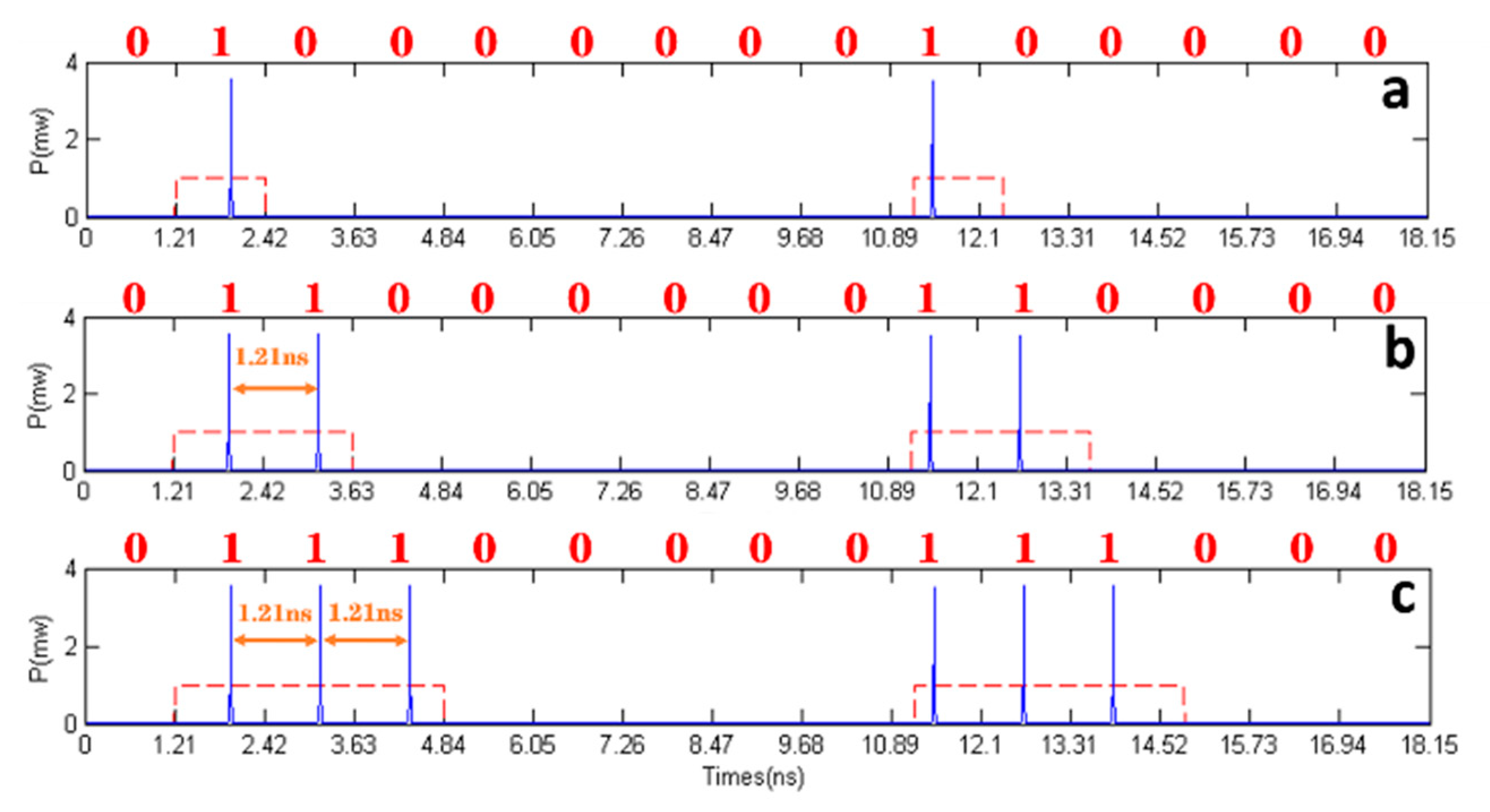
Firstly, the regular pulse stimulus is considered. Figure 2a–c show the spiking response of VCSEL-SA1 to the stimulus with the fixed k = 1.1 × 10 3 and different temporal durations Δ t of 1.21 ns, 2.42 ns, and 3.63 ns. The red dashed lines and the blue solid lines denote the input stimulus and corresponding spiking response, respectively. The binary series of ones and zeros are presented at the top of each diagram in Figure 2. When a 0 bit message is input, no spikes can emerge, which is identical to a free-running laser. When a 1 bit message is input, spikes can be excited once the excitable threshold is exceeded and the SA is saturated, resulting in the rapid release of the accumulated photon energy; then, the gain is depleted. As a result, a conversion from binary data to spike (BTS) is successfully realized.
Next, after taking into account that the BTS conversation rate limits the spike-based information transmission rate [22], Figure 3 gives the conversion rate variation with input strength under different bias currents. When the injection strength remains constant, a higher conversation rate can be obtained for higher bias current, which can be interpreted as the refractory period decreasing with increasing bias current; then, a smaller injection perturbation can meet the excitable threshold condition. Obviously, through controlling the injection strength and bias current, the BTS rate can be adjusted in a relatively large range even if the maximal conversion rate is limited by the slower of the two carrier lifetimes of the gain and SA [35], which can offer huge prospects for future neuromorphic computing.

3.2. Image Transmission

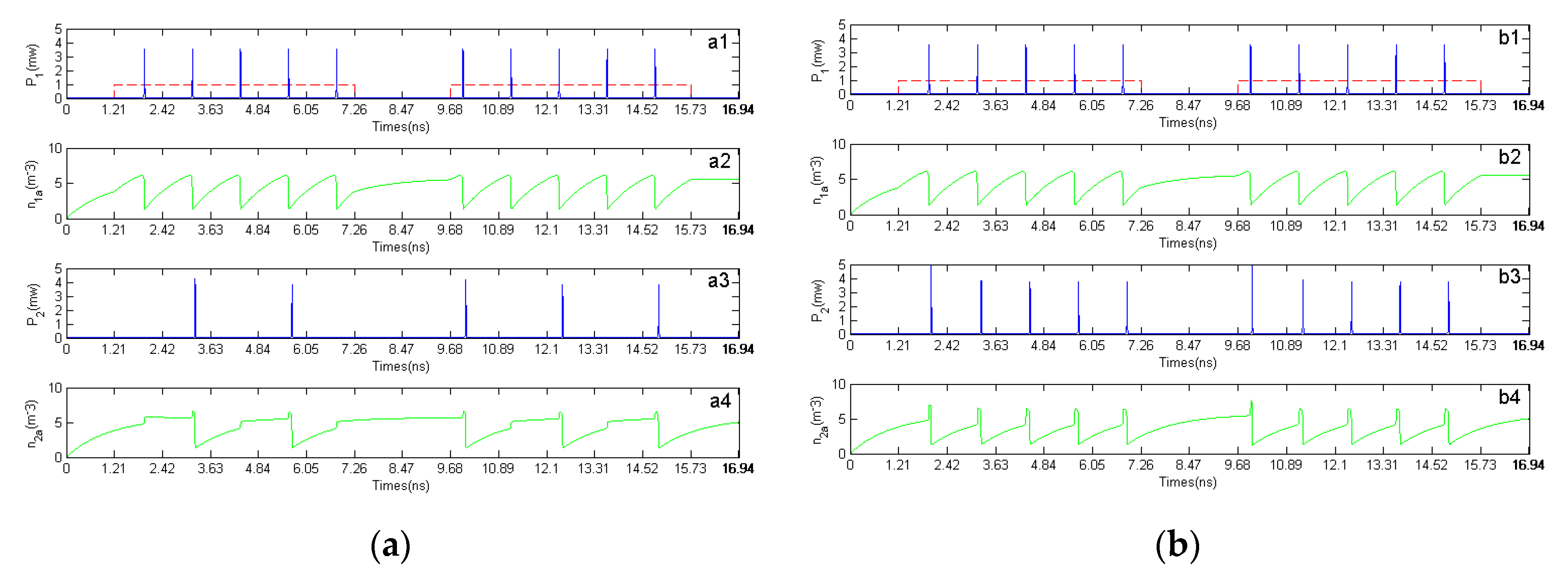
In natural biological neuron networks, different neurons can realize communication based on the transmission of the excited or suppressed spiking signals amongst neighboring neurons through their axons and dendrites. In particular, the precise timing of spikes without destroying their temporal structure is necessary for the successful communication. Figure 4 shows the spiking responses and n a variation of two cascaded VCSEL-SAs for different injection coupling weights, where the input strength k = 1.1 × 10⁻³. After taking into account that the injection coupling delay has no effect on the output characteristics except for the time shift of spiking response series in our work, τ i n j was set as 0 ns for simplicity. The red dashed lines and blue solid lines denote the binary encoded stimulus and the spiking response trains, respectively, while the green solid lines denote the variation of the number of carriers. Under external stimulus, VCSEL-SA1 fires five consecutive spike signals during the perturbation time, as shown in Figure 4a1 and b1. For a relatively low coupling weight of 0.007   mw 1 , as shown in Figure 4a3, the fired spiking pattern in VCSEL-SA1 can be propagated to VCSEL-SA2. However, only two or three spikes can be excited, and some spiking information is lost for this low coupling weight during the propagation. Then, upon increasing the coupling weight to 0.017 mw 1 , as shown in Figure 4b1–b4, the spiking events can be entirely propagated from VCSEL-SA1 to VCSEL-SA2. Hence, a proper coupling weight can guarantee the successful propagation of image-spiking patterns. This phenomenon can be interpreted as both the accumulated carrier density in the active region and the excited threshold of laser, which is approximately expressed as n a t h r e s h = ( τ p h η 0 s Γ s g s + 1 ) / ( τ p h Γ a g a ) + n 0 a , thus determining the spiking exciting phenomenon. Once the n a accumulates to exceed the exciting threshold, the spikes can be excited. Correspondingly, n a exhibits an evolution tendency of abrupt decrease and then gradual recovery, and vice versa. Figure 4 shows the corresponding evolution of n a . From these diagrams, one can see that, for a small coupling weight, a relatively longer accumulated time of n a to reach the exciting threshold is necessary due to the limitation of the refractory period in the VCSEL-SA neuron, and new stimulus events cannot excite the spikes during the carrier recovery. Upon further increasing the accumulation time until n a exceeds the exciting threshold, a new spike is excited. Therefore, it is necessary for the successful spike pattern propagation to increase the coupling weight to a certain level.
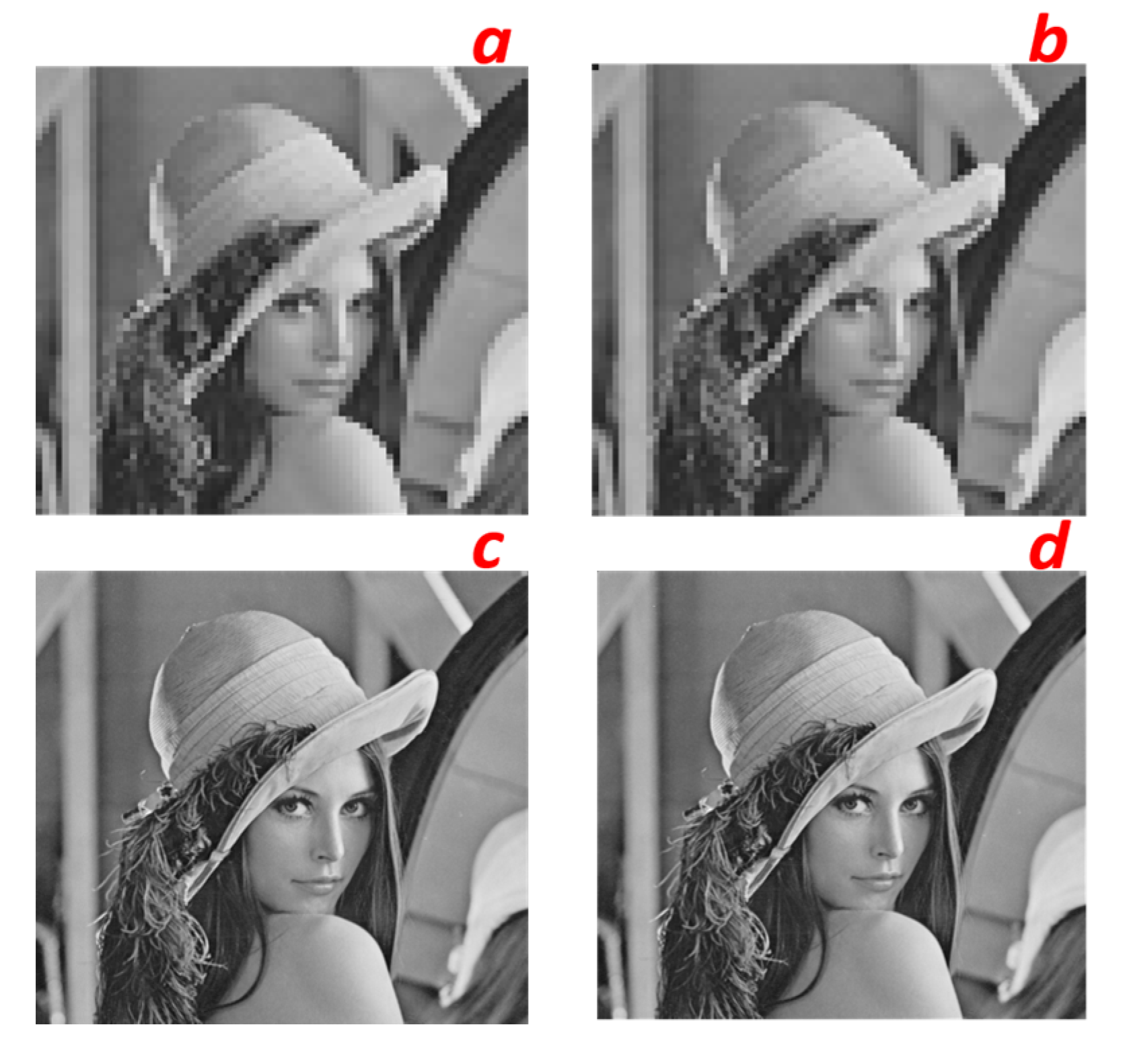
Next, we discuss the image transmission performance based on this proposed system. Figure 5a,b show the transmission quality of image with 73 × 73 pixels under k = 1.1 × 10⁻³. From this diagram, one can see that image transmission can be successfully achieved between two cascaded VCSEL-SA neurons under suitable conditions, which further verifies the results in Figure 4b1–b4. To further investigate the feasibility of this proposed method in image transmission, Figure 5c,d show the transmission results of high-resolution image with 512 × 512 pixels, where k = 1.1 × 10⁻³ and W12 = 0.017 mw−1. Obviously, the feasibility of the high-resolution image transmission based on spiking dynamics of electronically controlled VCSEL-SA can be demonstrated to a certain extent even though the image transmission with higher resolution is not considered due to the limited computing ability of our computer, which can open a new window for future high-speed information transmission of high-resolution images or full HD videos. In addition, we should note that, due to limitation of BTS conversation rate, high-speed image transmission can introduce higher BERs.
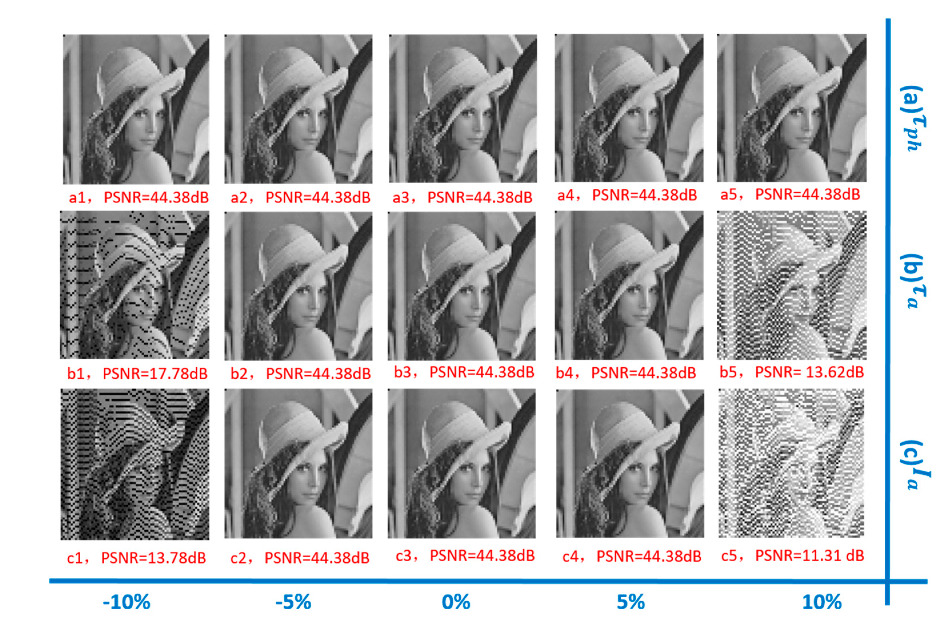
Generally, there exists a certain difference between two used lasers. Therefore, it is necessary to investigate the effect of several typical parameter mismatches on the spiking dynamics, and Figure 6 demonstrates the images transmission performance under a fixed coupling weight of 0.017 mw 1 , where several typical parameter mismatches including τ p h , τ a , and I a are considered. For simplicity, the parameter value of VCSEL-SA1 is fixed while some parameters of VCSEL-SA2 are adjusted. The relative mismatched parameters are defined as Δ τ p h = ( τ 2 p h     τ 1 p h ) / τ 1 p h , Δ τ a = ( τ 2 a     τ 1 a ) / τ 1 a , and Δ I a = ( I 2 a     I 1 a ) / I 1 a . From Figure 6, one can see that the image transmission is feasible when the two lasers are in a certain parameter mismatch range. However, when the parameter mismatch exceeds a certain level, the image PSNR decreases with the increase in mismatch degree, and the image is distorted accordingly. Moreover, compared with I a and τ a , mismatched τ p h has a relatively smaller influence on the image transmission performance.
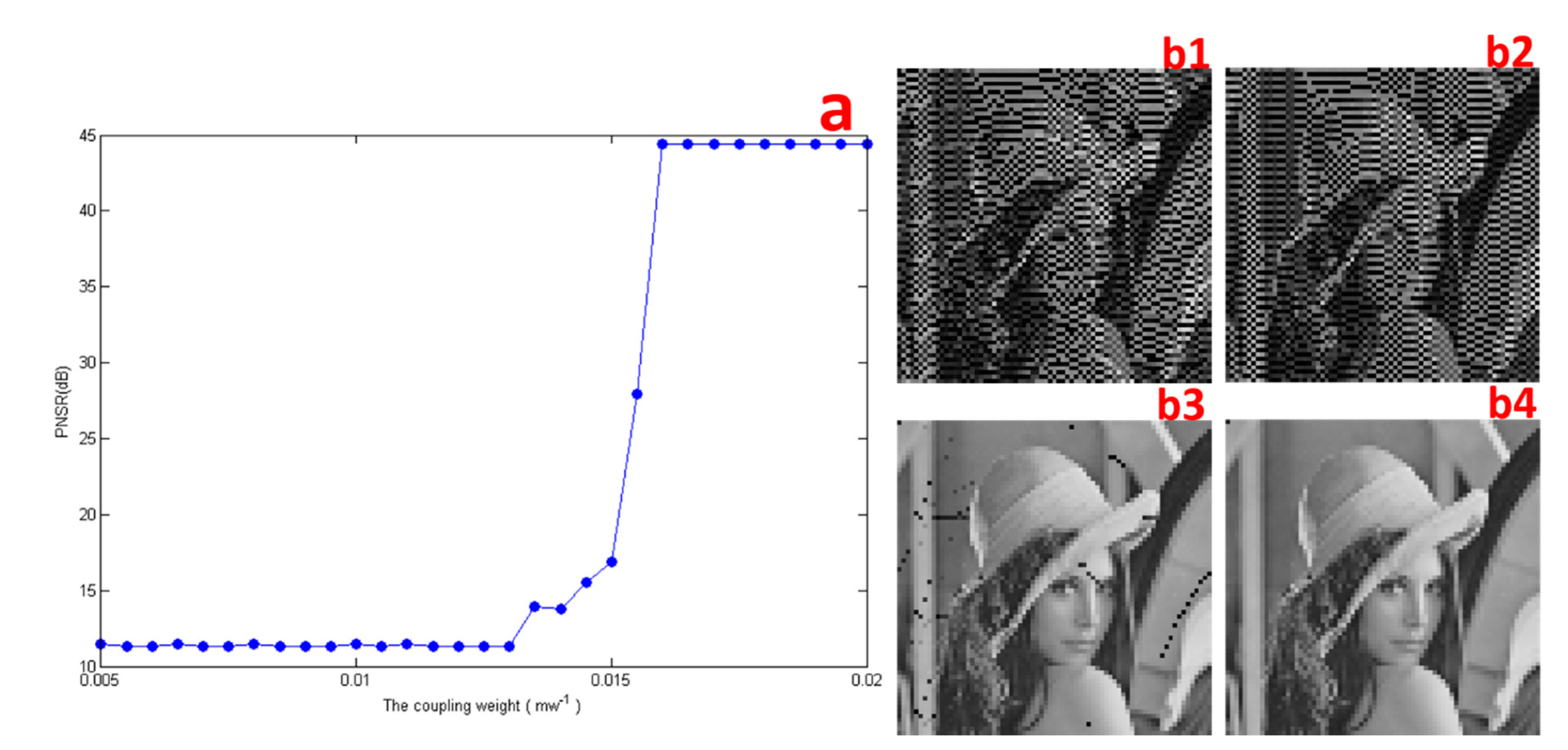
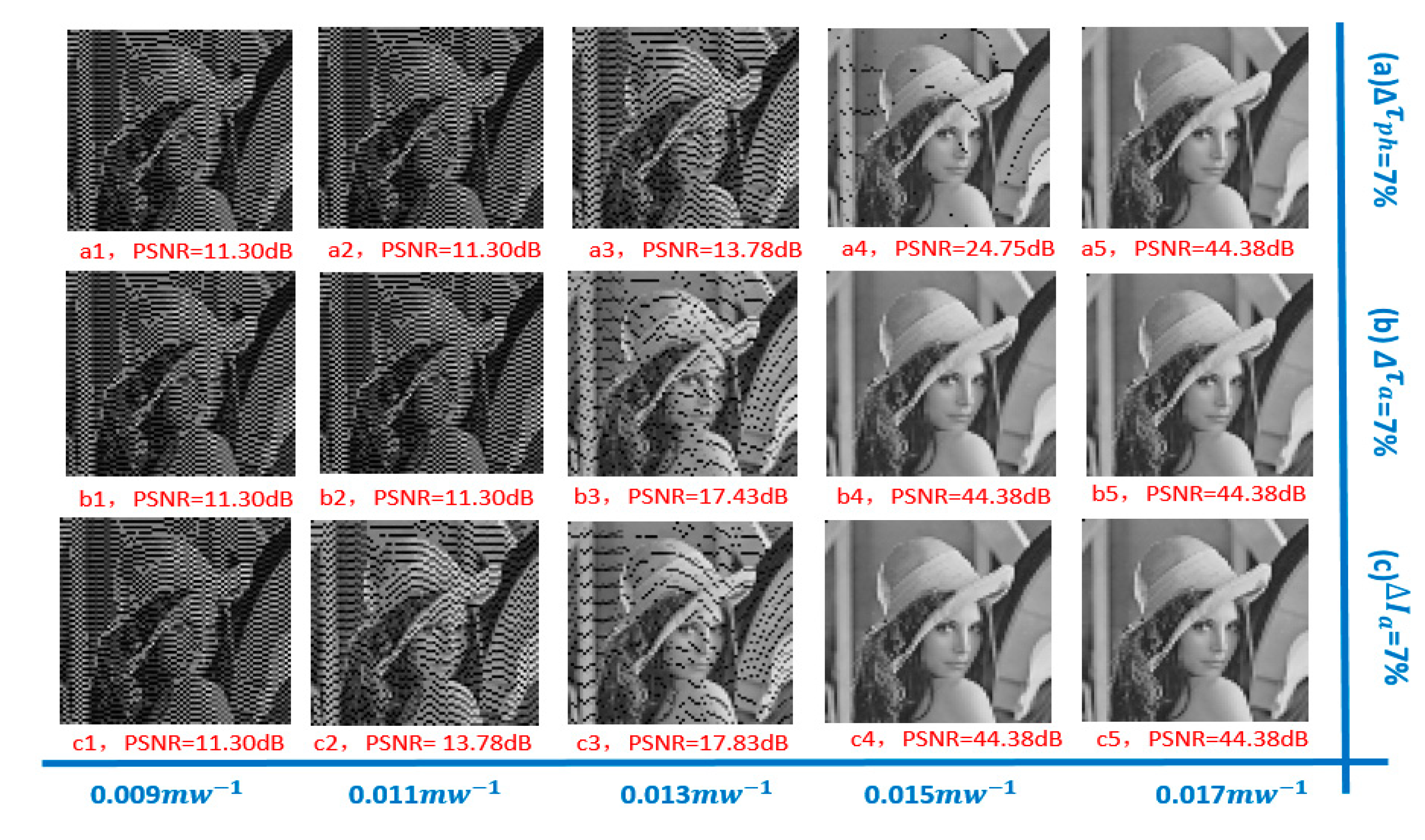
Figure 7 shows the PSNR variations of the output images with different coupling weight between the two lasers and corresponding transmitted images. From this diagram, one can see that PNSR gradually increases upon increasing the coupling weight, and then stabilizes at a certain level. When the coupling weight is relatively small, the transmitted images are seriously detorted and become very blurred, as shown in Figure 7(b1,b2). With increasing coupling weight, the images can be successfully transmitted, as shown in Figure 7(b3,b4). Moreover, Figure 8 gives the transmitted images for different coupling weight under 7 % mismatched parameters of τ p h   ( a ) , τ a   ( b ) , and I a   ( c ) . Upon increasing the coupling weight, the black spots in the image disappear and then the image becomes clear. Correspondingly, the PSNR of the output image increases. Obviously, typical parameter mismatches have some impact on the image transmission performance in our proposed cascaded system. By suitably increasing the coupling weight, the image propagation robustness to the parameter mismatches can be efficiently enhanced [33,36].
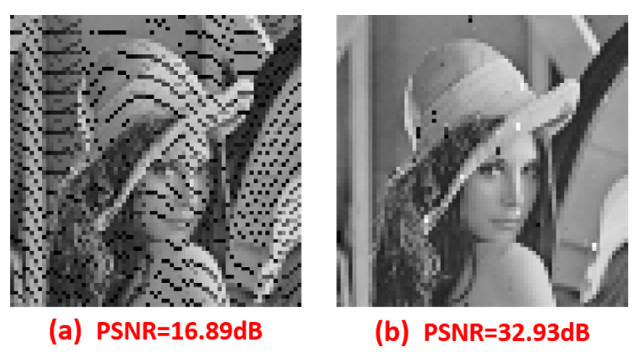
In a practical information transmission system, the device errors can also affect the information transmission performance, and different error correction methods have been adopted to assure successful information transmission [37,38]. Here, we further adopted the 8B10B conversion method to optimize the system communication performance. The decoded images before and after adopting the 8B10B method are shown in Figure 9, where k = 1.1 × 10⁻³ and W12 = 0.015 mw−1. From these diagrams, one can see that, under our simulation conditions, the decoded image quality is significantly improved after adopting this error correction method, which indicates that our proposed system can be applied in future image transmission after adopting a suitable error correction method. Moreover, the additional simulation results demonstrate that this proposed image transmission scheme has relatively good robustness to noise under our simulation conditions.

3.3. Storage of Spiking Patterns

Lastly, after adding the optoelectrical feedback loop to the first laser, the storage properties of image spiking patterns are discussed. Figure 10 shows the output time series of two cascaded VCSEL-SAs as response to the input stimulus (red dashed line), where Wf = 0.010 mw−1 and W12 = 0.017 mw−1. An injected rectangular pulse with k = 3 × 10⁻⁴ and Δ t = 8 ns was used to encode the injection perturbation. From these diagrams, one can see that, under an external stimulus, a three-spike burst is fired repetitively by VCSEL-SA1 with a fixed time interval corresponding to the feedback delay. This phenomenon can be interpreted as the first external perturbation firing three spikes for VCSEL-SA1, which can repetitively stimulate the VCSEL-SA1 through the added feedback loop. Consequently, a repeated spiking response can be observed, as shown in Figure 10b. Moreover, the spike responses of VCSEL-SA1 can be transmitted to VCSEL-SA2, as shown in Figure 10c. Obviously, the encoded spike information can be successfully stored in the electrically controlled cascaded system under this condition, which can be applied in future complex spiking pattern processing systems.

4. Conclusions

In conclusion, we demonstrated an image encoding and transmission system based on two electrically controlled vertical-cavity surface-emitting lasers with an embedded saturable absorber (VCSEL-SA). The simulation results show that, the conversion rate from binary code to spiking signal is highly dependent on the input strength and bias current. Under suitable conditions, the encoding images can be successfully transmitted in the proposed photonic neuron system. Moreover, typical parameter mismatches have some impact on the image transmission performance, and suitably increasing the coupling weight can improve the system robustness to parameter mismatches to a certain extent. Additionally, spiking patterns can be efficiently stored and transmitted in the electronically controlled cascaded system. This work is valuable for the future construction and application of large-scale neural networks based on photonic neurons.

Author Contributions

M.N. was responsible for the numerical simulation, analyzing the results, and the writing of the paper; X.T., Z.G., L.X., J.W., F.M. and Q.Z. were responsible for writing and revising the manuscript; X.L. and T.D. were responsible for the discussion of the results and reviewing/editing of the manuscript. All authors have read and agreed to the published version of the manuscript.

Funding

This research was funded by the National Natural Science Foundation of China (Grant No. 61875167), the Natural Science Foundation of Chongqing City (CSTC 2019jcyj-msxm X0136), the Fundamental Research Funds for the Central Universities of China (XDJK2020B053), and the National Training Program of Innovation and Entrepreneurship for Undergraduates College Students’ Innovation Fund of Southwest University under Grant No. 202010635089.

Institutional Review Board Statement

“Not applicable” for studies not involving humans or animals.

Informed Consent Statement

“Not applicable” for studies not involving humans.

Data Availability Statement

The data presented in this study are available on request from the corresponding author. The data are not publicly available as the data also forms part of an ongoing study.

Conflicts of Interest

The authors declare no conflict of interest.

References

  1. Yang, J.Q.; Wang, R.; Ren, Y.; Mao, J.Y.; Wang, Z.P.; Zhou, Y.; Han, S.T. Neuromorphic engineering: From biological to spike-based hardware nervous systems. Adv. Mater. 2020, 32, 2003610. [Google Scholar] [CrossRef] [PubMed]
  2. Zhang, M.; Gu, Z.; Pan, G. A survey of neuromorphic computing based on spiking neural networks. Chin. J. Electron. 2018, 27, 667–674. [Google Scholar] [CrossRef]
  3. Huang, H.; Ge, C.; Liu, Z.; Zhong, H.; Guo, E.; He, M.; Wang, C.; Yang, G.; Jin, K. Electrolyte-gated transistors for neuromorphic applications. J. Semicond. 2021, 42, 81–93. [Google Scholar] [CrossRef]
  4. Hasler, J.; Marr, B. Finding a roadmap to achieve large neuromorphic hardware systems. Front. Neurosci. 2013, 7, 118. [Google Scholar] [CrossRef] [Green Version]
  5. Roy, K.; Jaiswal, A.; Panda, P. Towards spike-based machine intelligence with neuromorphic computing. Nature 2019, 575, 607–617. [Google Scholar] [CrossRef] [PubMed]
  6. Watson, A. Neuromorphic engineering—Why can’t a computer be more like a brain. Science 1997, 277, 1934–1936. [Google Scholar] [CrossRef]
  7. Woods, D.; Naughton, T.J. Optical computing photonic neural networks. Nat. Phys. 2012, 8, 257–259. [Google Scholar] [CrossRef]
  8. James, C.D.; Aimone, J.B.; Miner, N.E.; Vineyard, C.M.; Rothganger, F.H.; Carlson, K.D.; Mulder, S.A.; Draelos, T.J.; Faust, A.; Marinella, M.J.; et al. A historical survey of algorithms and hardware architectures for neural-inspired and neuromorphic computing applications. Inspir. Cogn. Arc. 2017, 19, 49–64. [Google Scholar] [CrossRef] [Green Version]
  9. De Lima, T.F.; Peng, H.T.; Tait, A.N.; Nahmias, M.A.; Miller, H.B.; Shastri, B.J.; Prucnal, P.R. Machine learning with neuromorphic photonics. J. Lightwave Technol. 2019, 37, 1515–1534. [Google Scholar] [CrossRef]
  10. Xiang, S.Y.; Han, Y.N.; Song, Z.W.; Guo, X.X.; Zhang, Y.H.; Ren, Z.X.; Wang, S.H.; Ma, Y.T.; Zou, W.W.; Ma, B.W.; et al. A review: Photonics devices, architectures, and algorithms for optical neural computing. J. Semicond. 2021, 42, 023105. [Google Scholar] [CrossRef]
  11. Garbin, B.; Javaloyes, J.; Tissoni, G.; Barland, S. Topological solitons as addressable phase bits in a driven laser. Nat. Commun. 2015, 6, 5915. [Google Scholar] [CrossRef] [Green Version]
  12. Ren, H.; Fan, L.; Liu, N.; Wu, Z.; Xia, G. Generation of broadband optical frequency comb based on a gain-switching 1550 nm vertical-cavity surface-emitting laser under optical injection. Photonics 2020, 7, 95. [Google Scholar] [CrossRef]
  13. Zhong, D.Z.; Zeng, N.; Yang, H.; Xu, Z.; Hu, Y.; Zhao, K.K. Precise ranging for the multi-region by using multi-beam chaotic polarization components in the multiple parallel optically pumped spin-VCSELs with optical injection. Opt. Express 2021, 29, 7809–7824. [Google Scholar] [CrossRef]
  14. Iga, K. Surface-emitting laser—its birth and generation of new optoelectronics field. IEEE J. Sel. Top. Quantum Electron. 2000, 6, 1201–1215. [Google Scholar] [CrossRef]
  15. Koyama, F. Recent advances of VCSEL photonics. J. Lightwave Technol. 2006, 24, 4502–4513. [Google Scholar] [CrossRef]
  16. Liu, A.J.; Wolf, P.; Lott, J.A.; Bimberg, D. Vertical-cavity surface-emitting lasers for data communication and sensing. Photon. Res. 2019, 7, 121–136. [Google Scholar] [CrossRef]
  17. Hurtado, A.; Javaloyes, J. Controllable spiking patterns in long-wavelength vertical cavity surface emitting lasers for neuromorphic photonics systems. Appl. Phys. Lett. 2015, 107, 241103. [Google Scholar] [CrossRef] [Green Version]
  18. Robertson, J.; Deng, T.; Javaloyes, J. and Hurtado, A. Controlled inhibition of spiking dynamics in VCSELs for neuromorphic photonics: Theory and experiments. Opt. Lett. 2017, 42, 1560–1563. [Google Scholar] [CrossRef] [PubMed] [Green Version]
  19. Deng, T.; Robertson, J.; Hurtado, A. Controlled propagation of spiking dynamics in vertical-cavity surface-emitting lasers: Towards neuromorphic photonic network. IEEEJ. Sel. Top. Quantum Electron. 2017, 23, 1800408. [Google Scholar] [CrossRef] [Green Version]
  20. Nahmias, M.A.; Shastri, B.J.; Tait, A.N.; Prucnal, P.R. A leaky integrate-and-fire laser neuron for ultrafast cognitive computing. IEEE J. Sel. Top. Quantum Electron. 2013, 19, 1800212. [Google Scholar] [CrossRef]
  21. Barbay, S.; Kuszelewicz, R.; Yacomotti, A.M. Excitability in a semiconductor laser with saturable absorber. Opt. Lett. 2011, 36, 4476–4478. [Google Scholar] [CrossRef] [PubMed]
  22. Zhang, Z.X.; Wu, Z.M.; Lu, D.; Xia, G.Q.; Deng, T. Controllable spiking dynamics in cascaded VCSEL-SA photonic neurons. Nonlinear Dyn. 2020, 99, 1103–1114. [Google Scholar] [CrossRef]
  23. Shchukin, V.A.; Ledentsov, N.N.; Qureshi, Z.; Ingham, J.D.; Penty, R.V.; White, I.H.; Nadtochy, A.M.; Maximov, M.V.; Blokhin, S.A.; Karachinsky, L.Y.; et al. Digital data transmission using electro-optically modulated vertical-cavity surface-emitting laser with saturable absorber. Appl. Phys. Lett. 2014, 104, 051125. [Google Scholar] [CrossRef]
  24. Nugent, D.G.H.; Plumb, R.G.S.; Fisher, M.A.; Davies, D.A.O. Self-pulsations in vertical-cavity surface-emitting lasers. Electron. Lett. 1995, 31, 43–44. [Google Scholar] [CrossRef]
  25. Burr, G.W. A role for optics in AI hardware. Nature 2019, 569, 199–200. [Google Scholar] [CrossRef] [PubMed] [Green Version]
  26. Shen, Y.C.; Harris, N.C.; Skirlo, S.; Prabhu, M.; Baehr-Jones, T.; Hochberg, M.; Sun, X.; Zhao, S.J.; Larochelle, H.; Englund, D. Deep learning with coherent nanophotonic circuits. Nat. Photon. 2017, 11, 441–446. [Google Scholar] [CrossRef]
  27. Ren, Q.; Zhang, Y.L.; Wang, R.; Zhao, J.Y. Optical spike-timing-dependent plasticity with weight-dependent learning window and reward modulation. Opt. Express 2015, 23, 25247–25258. [Google Scholar] [CrossRef]
  28. Tan, H.L.; Li, Z.G.; Tan, Y.H.; Rahardja, S.; Yeo, C. A perceptually relevant mse-based image quality metric. IEEE Trans. Image Process. 2013, 22, 4447–4459. [Google Scholar]
  29. Wang, Z.; Bovik, A.C. Mean squared error: Love it or leave it? A new look at signal fidelity measures. IEEE Signal. Process. Mag. 2009, 26, 98–117. [Google Scholar] [CrossRef]
  30. Giudice, G.E.; Kuksenkov, D.V.; Temkin, H.; Lear, K.L. Differential carrier lifetime in oxide-confined vertical cavity lasers obtained from electrical impedance measurements. Appl. Phys. Lett. 1999, 74, 899–901. [Google Scholar] [CrossRef] [Green Version]
  31. Shastri, B.J.; Chen, C.; Choquette, K.D.; Plant, D.V. Circuit modeling of carrier-photon dynamics in composite-resonator vertical-cavity lasers. IEEE J. Quantum Elect. 2011, 47, 1537–1546. [Google Scholar] [CrossRef]
  32. Fledmann, J.; Youngblood, N.; Wright, C.D.; Bhaskaran, H.; Pernice, W.H.P. All-optical spiking neurosynaptic networks with self-learning capabilities. Nature 2019, 569, 208–214. [Google Scholar] [CrossRef] [PubMed] [Green Version]
  33. Prucnal, P.R.; Shastri, B.J. Neuromorphic Photonics; CRC Press: Boca Raton, FL, USA, 2017. [Google Scholar]
  34. Song, Z.W.; Xiang, S.Y.; Ren, Z.X.; Wang, S.H.; Wen, A.J.; Hao, Y. Photonic spiking neural network based on excitable VCSELs-SA for sound azimuth detection. Opt. Express 2020, 28, 1561–1573. [Google Scholar] [CrossRef]
  35. Ma, P.Y.; Shastri, B.J.; De Lima, T.F.; Tait, A.N.; Nahmias, M.A.; Prucnal, P.R. All-optical digital-to-spike conversion using a graphene excitable laser. Opt. Express 2017, 25, 33504–33513. [Google Scholar] [CrossRef]
  36. Kistler, W.M.; Gerstner, W. Stable propagation of activity pulses in populations of spiking neurons. Neural Comput. 2002, 14, 987–997. [Google Scholar] [CrossRef] [PubMed]
  37. Brakensiek, J.; Guruswami, V.; Zbarsky, S. Efficient low-redundancy codes for correcting multiple deletions. IEEE Trans. Inf. Theory 2016, 64, 3403–3410. [Google Scholar] [CrossRef] [Green Version]
  38. Sima, J.; Bruck, J. Optimal k-deletion correcting codes. IEEE Int. Symp. Inform. Theory France 2019, 67, 3360–3375. [Google Scholar] [CrossRef]
Figure 1. Schematic diagram of image transmission between two cascaded VCSEL-SAs. DC: direct current, ISO: optical isolator, VA: variable attenuator, PD: photodetector.
Photonics 08 00238 g001
Figure 2. Time series for VCSEL-SA1 output corresponding to the input stimulus under different temporal durations Δ t   of (a) 1.21 ns, (b) 2.42 ns, and (c) 3.63 ns, where red dashed lines and blue solid lines denote the binary encoded stimulus and the spiking response trains, respectively.
Photonics 08 00238 g002
Figure 3. Conversion rate variation with input strength k for various biasing currents.
Photonics 08 00238 g003
Figure 4. Spiking outputs (rows 1 and 3) and n a evolution (rows 2 and 4) in a two cascaded VCSEL-SA system for different coupling weights of 0.007 mw 1 (a) and 0.017 mw 1 (b), where Δ t = 6.05 ns, k = 1.1 × 10 3 , τ i n j = 0 ns.
Photonics 08 00238 g004
Figure 5. Transmission results between two cascaded VCSEL-SA neurons for different resolution images of 73 × 73 pixels (a,b) and 512 × 512 pixels (c,d), where (a,c) correspond to the original image and (b,d) correspond to the transmitted image.
Photonics 08 00238 g005
Figure 6. PSNRs of output images from VCSEL-SA2 for different parameter mismatches of (a) τ p h , (b) τ a , and (c) I a , where the first, second, third, and fourth columns respectively correspond to −10%, −5%, 0%, 5%, and 10% parameter mismatches.
Photonics 08 00238 g006
Figure 7. (a) PSNRs of output images from VCSEL-SA2 under different coupling weights; (b) the transmitted images for different coupling weights of (b1) 0.005, (b2) 0.010, (b3) 0.0155, and (b4) 0.020 mw−1.
Photonics 08 00238 g007
Figure 8. PSNRs of output images from VCSEL-SA2 under 7% parameter mismatches of (a) τ p h , (b) τ a , and (c) I a , where the first, second, third, fourth, and fifth columns respectively correspond to 0.009, 0.011, 0.013, 0.015, and 0.017 mw−1 coupling weight.
Photonics 08 00238 g008
Figure 9. The decoded images from VCSEL-SA2 without (a) and with (b) 8B10B conversion method, where W12 = 0.015 mw 1 .
Photonics 08 00238 g009
Figure 10. Storage of spiking patterns in two cascaded VCSEL-SAs with optoelectronic feedback under Wf = 0.010 mw−1, W12 = 0.017 mw−1, k = 3 × 10⁻⁴ and τinj = 2 ns, where (a) injected pulse, (b) spike trains from VCSEL-SA1 and (c) spike trains form VCSEL-SA2.
Photonics 08 00238 g010
Publisher’s Note: MDPI stays neutral with regard to jurisdictional claims in published maps and institutional affiliations.