Abstract
In this work, we demonstrate nonflat metasurface holograms with applications in imaging, sensing, and anticounterfeiting. For these holograms, the image and its symmetry properties, with respect to the polarization of the light, depend on the specific shape of the substrate. Additionally, the sensitivity of the holographic image to the substrate shape can be engineered by distributing the phase information into determined areas of the metasurface.
1. Introduction
Photonic metasurfaces (MSs) are one of the most successful platforms to realize computer-generated holograms. These devices use subwavelength pixels to create holographic images with high efficiency [1,2,3,4,5]. Holographic MSs enable the multiplexing of information in various degrees of freedom, including wavelength [6,7], angle [8], polarization [9,10,11,12,13], and image dimensionality [14]. Applications of MSs include the manipulation and storage of information [15,16], security [10], and displays [17].
MSs offer the possibility to modulate the amplitude and phase of light with a high resolution and negligible thickness. These properties make MSs easily exploitable in flexible designs. Examples of these applications include cloaking, lab-on-fiber, optically active, and filtering devices [18,19,20,21,22,23].
Flexibility has been previously exploited for MS hologram devices controlled by the degree of substrate stretching, e.g., to vary the color of an MS [24,25], the focus of an MS lens [26], or to alternate between multiple near-field images [27]. A theoretical exploration of flexible MS holograms has also enabled carpet cloaking, and spherical aberration correction for lensing applications [28]. Flexible MSs have also been used to decouple the shape of a lens from its optical function [29].
Traditional flat Pancharatnam–Berry MS holograms produce identical holographic images when illuminated by left-(LCP) and right-handed circularly polarized light (RCP) but with the holographic image rotated 180 degrees around the zeroth order of the beam [10]. These Pancharatnam–Berry MS holograms use geometric elements which encode, in their in-plane rotation angle, a dephasing value from 0 to 2. In this work, we demonstrate that for nonflat MSs, both the shape of the substrate and the polarization of the incident light contribute to the symmetry properties of the image. Here, we also describe how the sensitivity to the MS shape can be tailored to provide versatility for practical applications, including in anticounterfeiting and for surface topology sensors.
2. Rayleigh–Sommerfeld Light Propagation
We designed our holograms using the Gerchberg–Saxton iterative phase reconstruction algorithm. To describe the general case of propagation between the nonflat MS and the image planes, we adopted the full Rayleigh–Sommerfeld propagation method [30], as given by:
where the cartesian coordinates relate to the position vectors , U is the complex light field, k is the wavevector of light, and the holographic MS object and imaging planes are denoted with the subscripts respectively. Here, the coordinate system is aligned to the center of the undistorted MS. An illustration of this method can be seen in Figure 1.
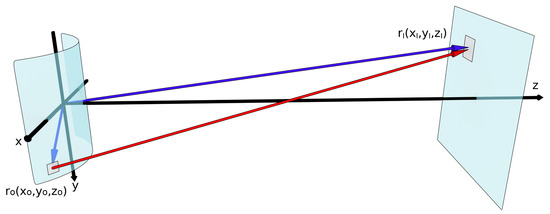
Figure 1.
Light propagation from to using the Rayleigh–Sommerfeld equation. The holographic image originates from the metasurface (MS) and is projected onto the screen.
For flat MSs, inverting the handedness of the polarization—for example, from RCP to LCP—typically creates a holographic image rotated by 180 degrees around the zeroth order of the holographic image [10]. This occurs because each Pancharatnam–Berry element provides the same dephasing but with an opposite sign between the two polarizations [1,31]. With more complex meta-atoms, a similar effect can be used to encode entirely different holographic images [32,33].
The rotation of the holographic image around the zeroth order can be described through the equation:
where and I are the intensity distributions in the holographic image plane for the rotated and nonrotated holographic images respectively. and refer to the position in the holographic image plane in the x and y directions, respectively, and the z coordinate is constant.
For the nonflat MS case, Equation (2) only holds approximately true when both the phase contribution from the polarization and the phase contribution from the MS shape are inverted [34]. There is a small residual phase distortion, however, which is the result of the relative dephasing between and for the two surface topology configurations. When is sufficiently large, this effect disappears.
As such, Equation (2) for the nonflat MS case is approximately true when:
For a flat MS, the phase contribution is necessarily 0, and changing the handedness of the polarization leads to a rotation of the holographic image by 180 degrees. Furthermore, there is no residual phase distortion, as and are equal.
3. Results and Discussion
When we design nonflat MS holograms using the Gerchberg–Saxton algorithm and numerically integrating Equation (1) to propagate the light between the hologram and holographic image planes, the recovered phase holograms are specific to the surface profile. Changing the MS shape will then result in a distorted holographic image. Our chosen holographic MS design used, as Pancharatnam–Berry dephasing elements, a regular array of gold nanorods sitting on a polymeric spacing layer deposited on a reflective gold backplane [34,35]. Fabrication details are provided in the Methods and Materials section. Each unit cell, comprising a nanorod separated by the thin dielectric layer from the gold backplane, can be approximated as an isotropically emitting Huygen’s source. The unit cell has a pitch of 300 nm in both directions, while the nanorods have a length of 200 nm, a width of 75 nm, and a thickness of 40 nm. The wavelength nm for all results in this paper. This three-layer structure is realized on a free-standing and flexible 2.6 m thick polymeric membrane. To define the nanorods on the top surface, we used a standard electron beam lithography procedure [35], followed by dry back etching of the unmasked superficial gold layer. The quality of the MS after lift-off is illustrated in Figure 2a with a SEM image. Figure 2b shows a typical flexible holographic MS applied to a nonflat surface.
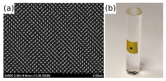
Figure 2.
(a) The nanorods comprising the MS and imaged with SEM after the membrane was lifted from the rigid initial substrate; (b) An experimental image displaying an MS conformed to a nonflat surface. The central patterned area appears darker due to the reduced reflectivity with respect to the surrounding region.
As described through Equations (1) and (2), to obtain a correctly rotated holographic image, it is necessary to change the symmetry of the substrate with respect to the plane (e.g., change z into ), as well as the handedness of the polarization. The experimental demonstration of this statement is displayed in Figure 3. The quality of the holographic image in Figure 3c is better than that of Figure 3b. This occurs as switching both the symmetry of the substrate and handedness of polarization still leaves a residual phase factor, which causes minor distortion. This effect is further detailed in Reference [34].
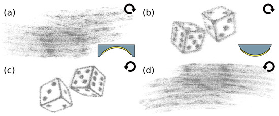
Figure 3.
Experimental holographic images where (a,b) were illuminated with right-handed (RCP) and (c,d) with left-handed circular polarizations (LCP), respectively, with nm. (a,c) used a concave substrate with a radius of curvature of 6 mm; (b,d) used a convex substrate with the same radius of curvature. The LCP images are rotated 180 degrees in the holographic image plane compared to the RCP images.
To evaluate the specificity of the holographic image to a particular substrate shape, we designed and fabricated holographic MSs for a flat surface, and convex cylinders with radii of curvature of 6 mm and 4 mm. We then compared the images obtained by these three MSs when applied to a cylinder with a radius of curvature of 6 mm. Simulations were performed by numerically integrating, using Equation (1), the complex hologram wave to find the complex wave in the holographic image plane. The intensity of this complex field gives us the holographic image as seen by the human eye or camera. As can be seen in Figure 4, the agreement between simulation and experiment is good. The greater the disparity between the surface shape that the MS hologram was designed for and the actual MS shape, the greater the distortion of the holographic image. A quantitative analysis of the distortion of the images was completed by evaluating the correlation coefficient of the intensity of the simulated holographic images compared to the ideal target image. Here a correlation coefficient of 1 means that the two images are identical, and a coefficient close to 0 means no correlation. Even in simulation, we do not expect a correlation coefficient of 1 because the number of iterations we perform during the phase retrieval is finite, and because we are encoding only the phase and not the amplitude information into the MS. Our analysis, as seen in the numbers in Figure 4, demonstrates that the correlation coefficient for holographic images where the MS has the correct surface shape is close to 1 but that the correlation coefficient drops to below half of this value when the MS has an incorrect shape [34].
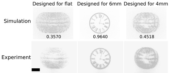
Figure 4.
Simulated and experimental holographic image results, comparing MS designed for various convex cylinders with differing radii of curvature. In each case, the MS was analyzed as being applied to a convex cylinder with a radius of curvature of 6 mm and nm. For the experimental results, the scale bar represents 10 mm. The numbers correspond to the correlation coefficient, where 1 is perfect correlation.
The sensitivity of the MS holograms to the surface shape can also be increased by carefully distributing the holographic phase information in the MS. For the specific example of cylindrical substrates with different radii of curvature, the gradient and position of the phase elements in the central region along the long axis of the cylinder are changed the least. As shown in detail in Reference [34], MSs with no phase information encoded in the central region maintained the peak holographic image quality, while increasing their sensitivity to the MS shape.
4. Materials and Methods
The following fabrication steps are illustrated in Figure 5. First, we spin-coated an Omnicoat (Microchem, Rugby, UK) polymeric sacrificial layer onto a silicon substrate at 1000 rpm for 1 min. The Omnicoat was then baked at 230 C for 1 min. Next, we spin-coated an SU-8 2000.5 and 2050 polymer (Microchem, Rugby, UK) blend (1:1) on top at 5000 rpm for 1 min to a thickness of 2.6 m. The SU-8 was then baked at 60 C for 1 min, and then 90 C for 4 min. This layer would act as the flexible substrate after removal of the Omnicoat. Next, we evaporated a 100 nm thick layer of gold to act as a backplane mirror. Next, we spin-coated an SU-8 2000.5 and Cyclopentanone blend (1:3) at 5000 rpm for 1 min to a thickness of 90 nm. The SU-8 was then baked at 60 C for 1 min, and then 90 C for 4 min. This layer would act as the dielectric spacer. We then crosslinked it with a flood UV exposure. Next, we evaporated an additional 40 nm of gold for the nanorods. Next, we spin-coated an SU-8 2000.5 and Cyclopentanone blend (1:2) at 5000 rpm for 1 min to a thickness of 100 nm. The SU-8 was then baked at 60 C for 1 min, and then 90 C for 4 min. This layer would act as the electron beam resist. Next, we patterned the nanorods using a top–down standard electron beam lithography approach and a RAITH eLine Plus lithography system at 30 keV. Next, we baked the SU-8 at 90 C for 2 min and developed it at room temperature in EC solvent (Microchem, Rugby, UK) for 1 min. Next, we used an Argon reactive ion etch to remove the unmasked gold. Last, we removed the Omnicoat sacrificial layer by dissolving it in MF319 solvent (Microchem, Rugby, UK) to leave a free-floating membrane. The device could then be manipulated with tweezers onto the chosen substrate.
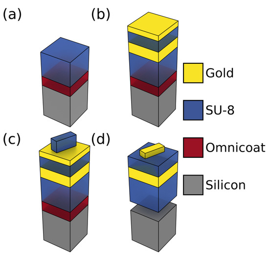
Figure 5.
The fabrication steps for our MS. (a) Spinning a lift-off layer and a thick SU-8 manipulation layer; (b) evaporation of two layers of gold spaced by an SU-8 layer; (c) spinning, electron beam exposure, and development of an SU-8 resist layer; (d) dry etching to remove unmasked gold and dissolving the Omnicoat layer.
5. Conclusions
We demonstrated a holographic MS where the holographic image has a strong dependence on the MS shape. Next, we described the additional symmetry condition that MS Pancharatnam–Berry holograms exhibit compared to their flat counterparts. We also showed how the holographic information in the MS can be encoded to tailor the sensitivity of the resulting holographic image to the MS shape. This work could be applied in fields ranging from sensors to anticounterfeiting devices and lenses.
6. Patents
Holographic device patent application. UK patent application number GB1719588.4.
Author Contributions
J.B. designed, fabricated and characterized the MSs. Both authors wrote the manuscript. A.D.F. directed the project.
Funding
This research was funded by EPSRC grant numbers EP/M508214/1 and EP/L017008/1.
Acknowledgments
J.B. and A.D.F. acknowledge support from EPSRC (Grant Nos. EP/M508214/1 and EP/L017008/1). The research data supporting this publication can be accessed at http://dx.doi.org/10.17630/583a258e-32cb-4a6b-826c-ab7d3b4429e2.
Conflicts of Interest
The authors declare no conflict of interest.
References
- Zheng, G.; Mühlenbernd, H.; Kenney, M.; Li, G.; Zentgraf, T.; Zhang, S. Metasurface holograms reaching 80% efficiency. Nat. Nanotechnol. 2015, 10, 308–312. [Google Scholar] [CrossRef] [PubMed]
- Arbabi, A.; Horie, Y.; Ball, A.; Bagheri, M.; Faraon, A. Subwavelength-thick lenses with high numerical apertures and large efficiency based on high-contrast transmitarrays. Nat. Commun. 2015, 6, 7069. [Google Scholar] [CrossRef] [PubMed]
- Arbabi, A.; Horie, Y.; Bagheri, M.; Faraon, A. Dielectric metasurfaces for complete control of phase and polarization with subwavelength spatial resolution and high transmission. Nat. Nanotechnol. 2015, 10, 937–943. [Google Scholar] [CrossRef] [PubMed]
- Wei, Z.; Cao, Y.; Su, X.; Gong, Z.; Long, Y.; Li, H. Highly efficient beam steering with a transparent metasurface. Opt. Express 2013, 21, 10739–10745. [Google Scholar] [CrossRef] [PubMed]
- Wang, L.; Kruk, S.; Tang, H.; Li, T.; Kravchenko, I.; Neshev, D.N.; Kivshar, Y.S. Grayscale transparent metasurface holograms. Optica 2016, 3, 1504–1505. [Google Scholar] [CrossRef]
- Montelongo, Y.; Tenorio-Pearl, J.O.; Williams, C.; Zhang, S.; Milne, W.I.; Wilkinson, T.D. Plasmonic nanoparticle scattering for color holograms. Proc. Natl. Acad. Sci. USA 2014, 111, 12679–12683. [Google Scholar] [CrossRef] [PubMed]
- Li, X.; Chen, L.; Li, Y.; Zhang, X.; Pu, M.; Zhao, Z.; Ma, X.; Wang, Y.; Hong, M.; Luo, X. Multicolor 3D meta-holography by broadband plasmonic modulation. Sci. Adv. 2016, 2, e1601102. [Google Scholar] [CrossRef]
- Kamali, S.M.; Arbabi, E.; Arbabi, A.; Horie, Y.; Faraji-Dana, M.; Faraon, A. Angle-multiplexed metasurfaces: Encoding independent wavefronts in a single metasurface under different illumination angles. Phys. Rev. X 2017, 7, 041056. [Google Scholar] [CrossRef]
- Liu, H.C.; Yang, B.; Guo, Q.; Shi, J.; Guan, C.; Zheng, G.; Mühlenbernd, H.; Li, G.; Zentgraf, T.; Zhang, S. Single-pixel computational ghost imaging with helicity-dependent metasurface hologram. Sci. Adv. 2017, 3, e1701477. [Google Scholar] [CrossRef]
- Wen, D.; Yue, F.; Li, G.; Zheng, G.; Chan, K.; Chen, S.; Chen, M.; Li, K.F.; Wong, P.W.H.; Cheah, K.W.; et al. Helicity multiplexed broadband metasurface holograms. Nat. Commun. 2015, 6, 8241. [Google Scholar] [CrossRef]
- Montelongo, Y.; Tenorio-Pearl, J.; Milne, W.; Wilkinson, T. Polarization switchable diffraction based on subwavelength plasmonic nanoantennas. Nano Lett. 2013, 14, 294–298. [Google Scholar] [CrossRef] [PubMed]
- Ye, W.; Zeuner, F.; Li, X.; Reineke, B.; He, S.; Qiu, C.W.; Liu, J.; Wang, Y.; Zhang, S.; Zentgraf, T. Spin and wavelength multiplexed nonlinear metasurface holography. Nat. Commun. 2016, 7, 11930. [Google Scholar] [CrossRef] [PubMed]
- Khorasaninejad, M.; Ambrosio, A.; Kanhaiya, P.; Capasso, F. Broadband and chiral binary dielectric meta-holograms. Sci. Adv. 2016, 2, e1501258. [Google Scholar] [CrossRef] [PubMed]
- Huang, L.; Mühlenbernd, H.; Li, X.; Song, X.; Bai, B.; Wang, Y.; Zentgraf, T. Broadband hybrid holographic multiplexing with geometric metasurfaces. Adv. Mater. 2015, 27, 6444–6449. [Google Scholar] [CrossRef] [PubMed]
- Nobukawa, T.; Nomura, T. Multilayer recording holographic data storage using a varifocal lens generated with a kinoform. Opt. Lett. 2015, 40, 5419–5422. [Google Scholar] [CrossRef] [PubMed]
- Shimada, K.I.; Ide, T.; Shimano, T.; Anderson, K.; Curtis, K. New optical architecture for holographic data storage system compatible with Blu-ray DiscTM system. Opt. Eng. 2014, 53, 025102. [Google Scholar] [CrossRef]
- Huang, L.; Chen, X.; Mühlenbernd, H.; Zhang, H.; Chen, S.; Bai, B.; Tan, Q.; Jin, G.; Cheah, K.W.; Qiu, C.W.; Li, J.; Zentgraf, T.; Zhang, S. Three-dimensional optical holography using a plasmonic metasurface. Nat. Commun. 2013, 4, 2808. [Google Scholar] [CrossRef]
- Di Falco, A.; Ploschner, M.; Krauss, T. Flexible metamaterials at visible wavelengths. New J. Phys. 2010, 12, 113006. [Google Scholar] [CrossRef]
- Reader-Harris, P.; Di Falco, A. Nanoplasmonic filters for hollow core photonic crystal fibers. ACS Photonics 2014, 1, 985–989. [Google Scholar] [CrossRef]
- Reader-Harris, P.; Ricciardi, A.; Krauss, T.; Di Falco, A. Optical guided mode resonance filter on a flexible substrate. Opt. Express 2013, 21, 1002–1007. [Google Scholar] [CrossRef] [PubMed]
- Di Falco, A.; Zhao, Y.; Alú, A. Optical metasurfaces with robust angular response on flexible substrates. Appl. Phys. Lett. 2011, 99, 163110. [Google Scholar] [CrossRef]
- Yang, S.; Liu, P.; Yang, M.; Wang, Q.; Song, J.; Dong, L. From flexible and stretchable meta-atom to metamaterial: A wearable microwave meta-skin with tunable frequency selective and cloaking effects. Sci. Rep. 2016, 6, 21921. [Google Scholar] [CrossRef] [PubMed]
- Walia, S.; Shah, C.; Gutruf, P.; Nili, H.; Chowdhury, D.R.; Withayachumnankul, W.; Bhaskaran, M.; Sriram, S. Flexible metasurfaces and metamaterials: A review of materials and fabrication processes at micro-and nano-scales. Appl. Phys. Lett. 2015, 2, 011303. [Google Scholar] [CrossRef]
- Song, S.; Ma, X.; Pu, M.; Li, X.; Liu, K.; Gao, P.; Zhao, Z.; Wang, Y.; Wang, C.; Luo, X. Actively tunable structural color rendering with tensile substrate. Adv. Opt. Mater. 2017, 5, 1600829. [Google Scholar] [CrossRef]
- Tseng, M.L.; Yang, J.; Semmlinger, M.; Zhang, C.; Nordlander, P.; Halas, N.J. Two-dimensional active tuning of an aluminum plasmonic array for full-spectrum response. Nano Lett. 2017, 17, 6034–6039. [Google Scholar] [CrossRef] [PubMed]
- Ee, H.S.; Agarwal, R. Tunable metasurface and flat optical zoom lens on a stretchable substrate. Nano Lett. 2016, 16, 2818–2823. [Google Scholar] [CrossRef] [PubMed]
- Malek, S.C.; Ee, H.S.; Agarwal, R. Strain multiplexed metasurface holograms on a stretchable substrate. Nano Lett. 2017, 17, 3641–3645. [Google Scholar] [CrossRef] [PubMed]
- Cheng, J.; Jafar-Zanjani, S.; Mosallaei, H. All-dielectric ultrathin conformal metasurfaces: Lensing and cloaking applications at 532 nm wavelength. Sci. Rep. 2016, 6, 38440. [Google Scholar] [CrossRef]
- Kamali, S.M.; Arbabi, A.; Arbabi, E.; Horie, Y.; Faraon, A. Decoupling optical function and geometrical form using conformal flexible dielectric metasurfaces. Nat. Commun. 2016, 7, 11618. [Google Scholar] [CrossRef]
- Veerman, J.A.; Rusch, J.J.; Urbach, H.P. Calculation of the Rayleigh–Sommerfeld diffraction integral by exact integration of the fast oscillating factor. JOSA A 2005, 22, 636–646. [Google Scholar] [CrossRef]
- Huang, Y.W.; Chen, W.T.; Tsai, W.Y.; Wu, P.C.; Wang, C.M.; Sun, G.; Tsai, D.P. Aluminum plasmonic multicolor meta-hologram. Nano Lett. 2015, 15, 3122–3127. [Google Scholar] [CrossRef] [PubMed]
- Mueller, B.; Rubin, N.; Devlin, R.; Groever, B.; Capasso, F. Metasurface Polarization Optics: Independent Phase Control of Arbitrary Orthogonal States of Polarization. Phys. Rev. Lett. 2017, 118, 113901. [Google Scholar] [CrossRef] [PubMed]
- Wen, D.; Chen, S.; Yue, F.; Chan, K.; Chen, M.; Ardron, M.; Li, K.F.; Wong, P.W.H.; Cheah, K.W.; Pun, E.Y.B.; et al. Metasurface Device with Helicity-Dependent Functionality. Adv. Opt. Mater. 2016, 4, 321–327. [Google Scholar] [CrossRef]
- Burch, J.; Di Falco, A. Surface topology specific metasurface holograms. ACS Photonics 2018, 5, 1762–1766. [Google Scholar] [CrossRef]
- Burch, J.; Wen, D.; Xianzhong, C.; Di Falco, A. Conformable Holographic Metasurfaces. Sci. Rep. 2017, 7, 4520. [Google Scholar] [CrossRef] [PubMed]


© 2019 by the authors. Licensee MDPI, Basel, Switzerland. This article is an open access article distributed under the terms and conditions of the Creative Commons Attribution (CC BY) license (http://creativecommons.org/licenses/by/4.0/).