1. Introduction
The rapid advancements in fields such as flexible structures, soft robots, aviation composite skin materials, and intelligent wearable devices have imposed stringent engineering demands on two-dimensional large-deformation, distributed, and multi-point synchronous strain measurement technologies [
1,
2,
3]. Accurately acquiring the distribution patterns and dynamic response characteristics of the two-dimensional global strain field on the surface of structures is the core basis for analyzing structural mechanical behavior, predicting fatigue damage, and optimizing the structural design of flexible components [
4,
5,
6]. Traditional strain detection technologies exhibit significant application limitations. Resistance strain gauges are only suitable for detecting small strain in rigid structures, exhibit poor ductility, are prone to detachment, and require cumbersome multi-point wiring, with weak anti-interference capabilities. Although machine vision digital speckle measurement can achieve two-dimensional full-field detection, it incurs high equipment costs and demands stringent lighting conditions for the testing environment, making it difficult to adapt to long-term online dynamic monitoring scenarios. Conventional single-point sensor devices can only collect data from discrete points and cannot accurately reconstruct continuous two-dimensional strain fields, thus failing to meet the high-precision testing requirements under large deformation conditions of flexible structures [
7,
8,
9]. Therefore, developing a highly adaptable, wide-range, multi-point distributed two-dimensional strain sensing technology is a key issue that urgently needs to be addressed in the field of intelligent structural monitoring.
Fiber Bragg Grating (FBG) sensing technology, with its outstanding advantages of small size, high sensitivity, corrosion resistance, electromagnetic interference resistance, and distributed array networking, has completely broken through the technical barriers of traditional electrical sensors and is widely used in various structural health monitoring and mechanical testing scenarios [
10,
11,
12,
13]. Compared to traditional single-point FBG sensors, FBG arrays can integrate multiple sensing units on a single optical fiber, achieving multi-point synchronization, long-distance, and distributed sensing and detection. They can efficiently capture the deformation information of the entire structure, providing reliable technical support for global strain field testing [
14,
15,
16,
17]. At present, FBG sensing technology has gradually been applied to flexible structure monitoring, but there are still obvious shortcomings in existing sensor devices. Most sensors rely on rigid substrate packaging, with extremely poor deformation ability, and can only achieve small-range one-dimensional strain measurement, which cannot adapt to the large-scale deformation characteristics of flexible structures [
18,
19,
20,
21]. A few flexible substrate fiber optic sensors have problems with a single structural design and severe bidirectional strain coupling interference, making it difficult to achieve independent strain decoupling measurement in two-dimensional directions, greatly limiting their application in complex two-dimensional deformation scenarios [
22,
23].
Polymer flexible films have excellent properties such as ultra-high ductility, good mechanical adhesion, low mechanical hysteresis, and lightweight flexibility. They can achieve synchronous large deformation with flexible substrates and are an ideal packaging substrate material for large-strain sensing devices. They can effectively solve the problems of strong rigidity, small range, and poor adhesion of traditional fiber optic sensors [
24,
25]. Integrating FBG arrays with polymer flexible films can combine the advantages of multi-point distributed sensing of fiber optic arrays with the large deformation mechanical properties of polymer films, providing a new technical solution for achieving precise measurement of two-dimensional large strain at multiple points. This has become a research hotspot in the field of flexible fiber optic sensing in recent years [
26,
27]. Reference [
28] reports a low-hysteresis FBG array on a PDMS/SiO
2 hybrid substrate for ultra-large-strain measurement. The present work shares the PDMS/SiO
2 hybrid substrate concept, but focuses on an orthogonally arranged bent fiber path and its direction-dependent responses under X- and Y-direction loading. This directional arrangement and the analysis of cross-axis coupling distinguish the focus of the present study from the ultra-large-strain measurement in Reference [
28]. At present, although preliminary composites of flexible substrates and FBG have been achieved in relevant research both domestically and internationally, there are still many technical bottlenecks. Most studies have not optimized the two-dimensional arrangement structure of FBG arrays, resulting in significant bidirectional strain cross-interference and low strain decoupling accuracy. The adhesion between the film and the fiber optic packaging interface is poor, and slip and delamination phenomena are prone to occur under high strain conditions, resulting in a significant decrease in sensing linearity and repeatability, making it impossible to achieve stable and accurate two-dimensional multi-point large-strain measurement [
28,
29,
30].
Related optical sensing approaches include “3D hybrid arrayed Ag/MOF multi-plasmon resonant cavity system for high-performance SPR sensing” [
31] and “Six-band high-sensitivity terahertz absorption device based on AlCuFe quasicrystals for sensing applications” [
32]. These studies illustrate how engineered structures tailor optical responses for SPR and refractive-index sensing, respectively, whereas the present FBG structure converts film deformation into wavelength shifts.
In response to the technical pain points of existing flexible fiber optic sensors, such as single measurement dimension, limited strain range, weak two-dimensional decoupling ability, and poor multi-point measurement stability, this paper designs and develops a FBG array composite polymer flexible film two-dimensional large-strain multi-point measurement sensor. By optimizing the layout structure of orthogonal FBG arrays, independent two-dimensional sensing and detection units are constructed to achieve precise decoupling of two-dimensional strain in both the X- and Y-directions. Using high elasticity polymer flexible film as the integrated packaging substrate and optimizing the vacuum bonding packaging process, ensuring synchronous deformation between the sensing unit and the substrate, greatly improves the sensor’s ability to adapt to large strains and testing stability. This sensor combines multiple advantages of multi-point distributed detection, large-scale deformation adaptation, and two-dimensional global strain measurement, effectively compensating for the shortcomings of traditional sensing technology.
2. Sensor Structure Design and Theoretical Analysis
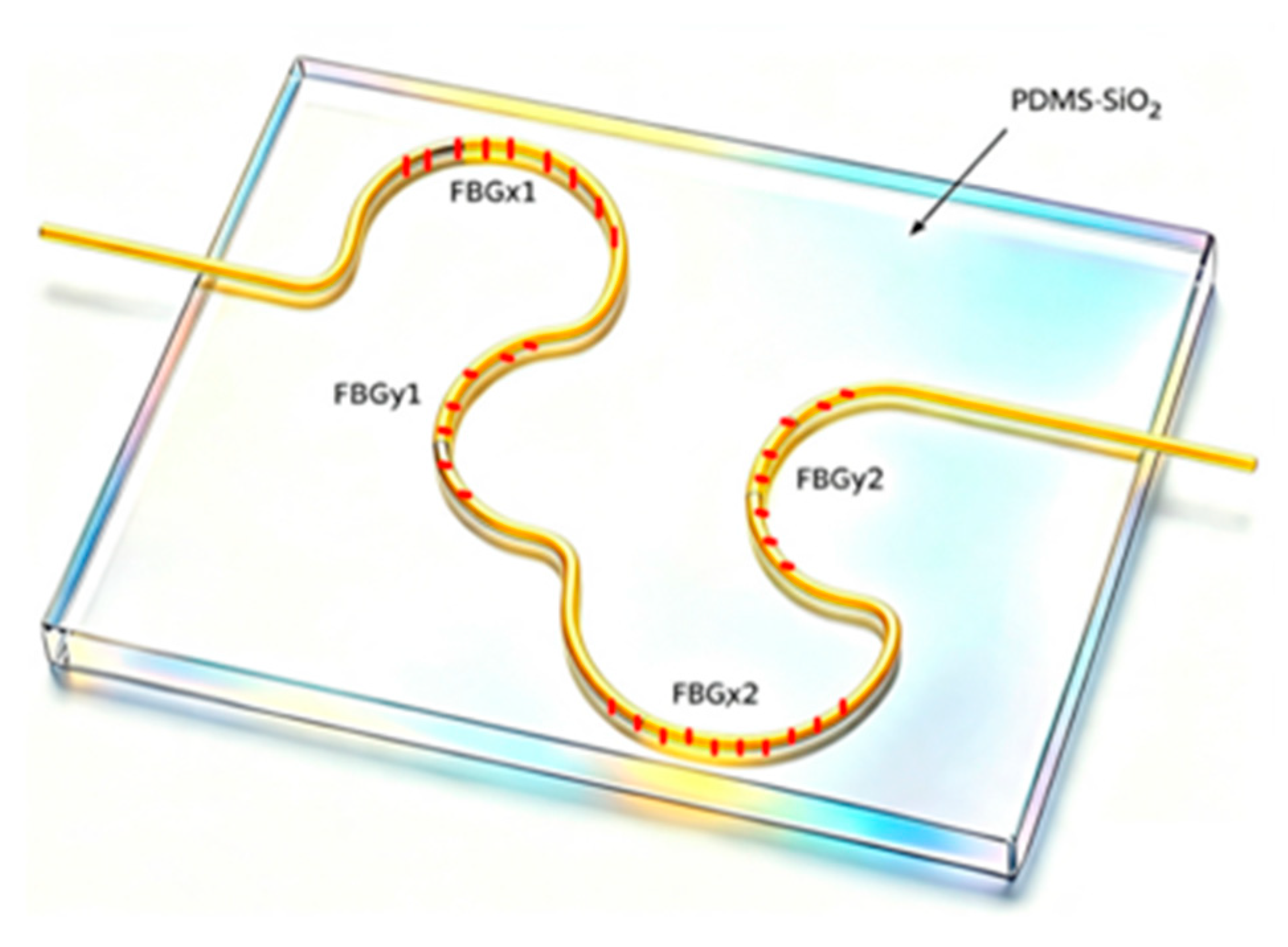
The proposed two-dimensional large-strain flexible FBG sensor consists of a PDMS/SiO
2 hybrid flexible film, an integrated orthogonal bending optical fiber bonded to the surface, and four FBG sensing units. The optical fiber is arranged as a whole on the surface of the PDMS/SiO
2 mixed substrate film and is tightly integrated with the film surface using epoxy resin adhesive. Four FBGs are arranged in the semi-circular characteristic area of the bent optical fiber, as shown in
Figure 1. According to the local tangential direction, they can be divided into two groups. FBGx1 and FBGx2 mainly respond to in-plane tensile deformation in the X-direction, while FBGy1 and FBGy2 mainly respond to in-plane tensile deformation in the Y-direction.
The central reflection wavelength of FBG satisfies the Bragg condition
Among them,
is the Bragg center wavelength of the i-th FBG.
is the effective refractive index of the fiber core.
is the FBG period. When optical fibers are subjected to axial strain and temperature disturbances, the FBG period and effective refractive index change simultaneously. By differentiating Equation (1), we can obtain
Under the small strain photoelastic approximation, the strain response of FBG can be written as
Among them, is the average strain of the i-th FBG along the fiber axis. is the temperature change. is the thermal expansion coefficient of the fiber. is the thermal optical coefficient. is the effective elastic optical coefficient of the fiber.
Let the initial centerline curvature of the i-th curved segment be
The corresponding bending radius is
During the stretching process of the thin film, the semi-circular fiber path undergoes geometric reconstruction, with a curvature of
. In order to ensure reliable operation of the sensor under high strain, it is necessary to simultaneously satisfy axial strain constraints and bending radius constraints
Among them, is the safe axial strain that FBG can withstand. is the minimum allowable bending radius to avoid excessive bending loss and mechanical damage.
After constant temperature or temperature compensation, the responses of FBGx1 and FBGy1 can be written in matrix form
where
Kxx and
Kxy denote the sensitivities of FBGx1 to X- and Y-direction strain, respectively, and
Kyx and
Kyy denote the sensitivities of FBGy1 to X- and Y-direction strain, respectively. The four coefficients are obtained from the four available uniaxial calibration responses. Each coefficient has units of nm/% when strain is expressed in %. The matrix accounts for cross-axis sensitivity, and its inversion requires det(K) = K
xxK
yy − K
xyK
yx ≠ 0 and consistent reference wavelengths. Within this calibrated linear model, the corresponding strain components are recovered by matrix inversion:
The cross-axis coefficients are therefore retained rather than assumed to be zero. The present experiments are uniaxial and sequential; simultaneous X–Y loading is required to directly validate the complete two-dimensional vector reconstruction.
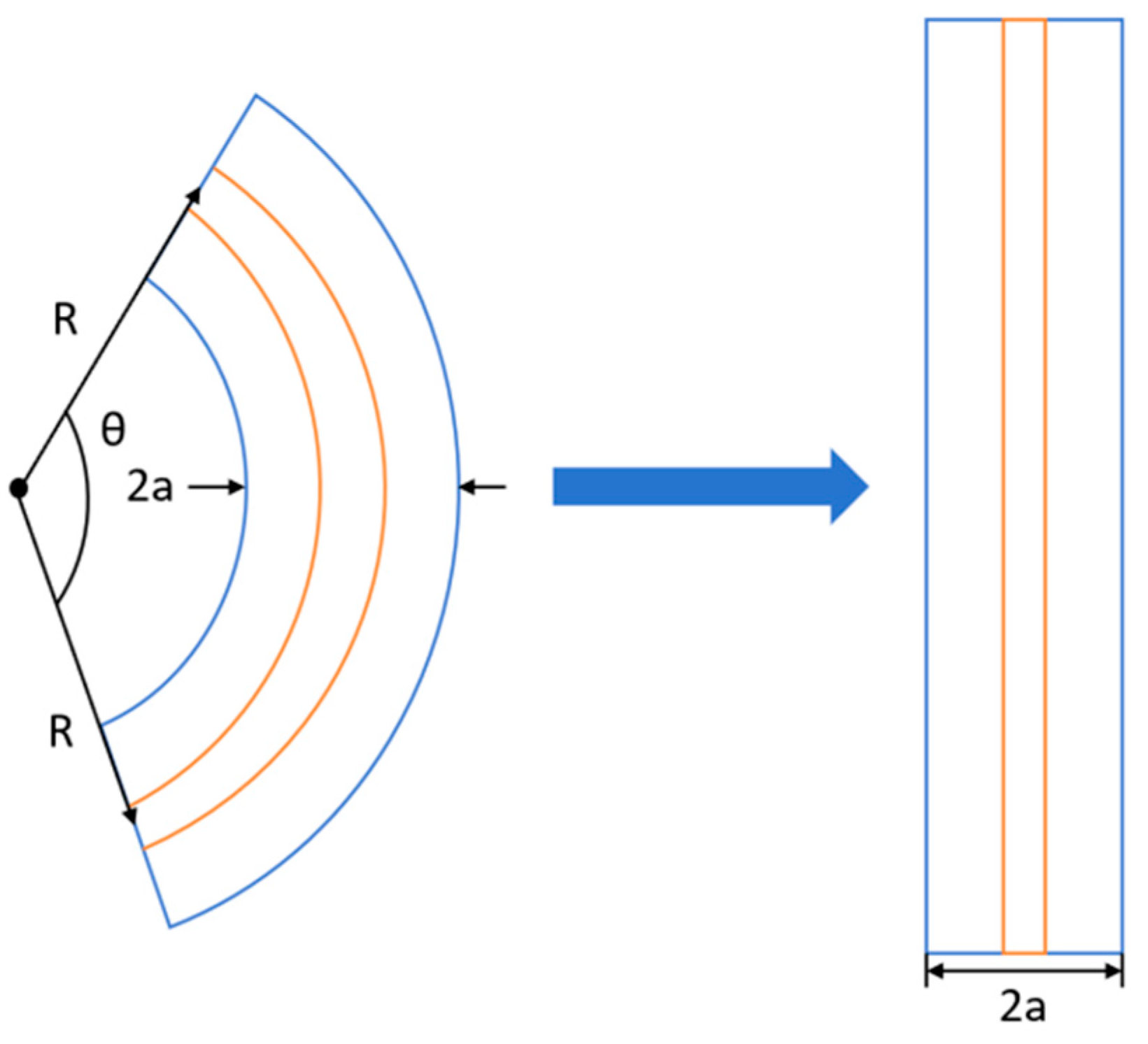
For the fiber with a bending radius of R, the refractive index distribution in its equivalent straight fiber can be written as
In the formula,
neq(
x,
y) is the equivalent refractive index after conformal mapping.
n(
x,
y) is the original refractive index distribution of the fiber in a straight-line state. x and y are the spatial coordinates of the fiber. R is the curvature radius of the bent optical fiber. As the bending radius decreases, the x/R term increases, and the non-uniformity of the refractive index is enhanced, as shown in
Figure 2.
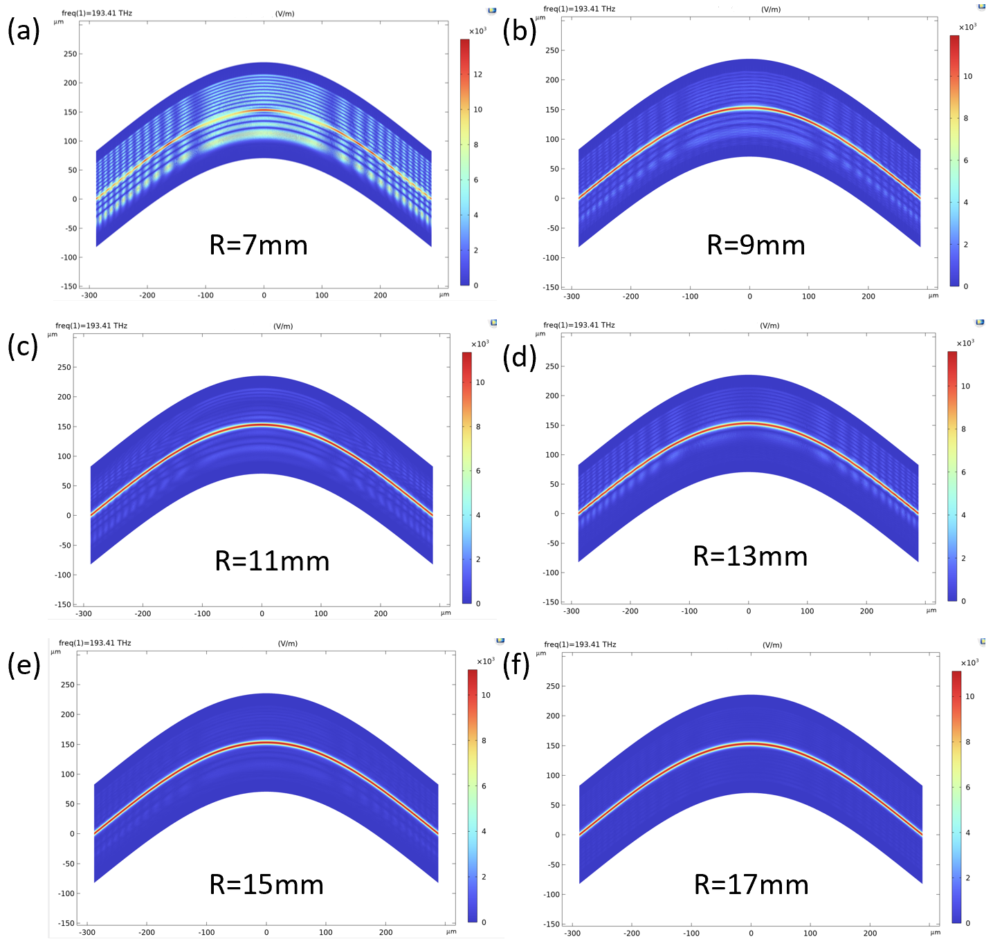
Based on the above equivalent refractive index model, a two-dimensional equivalent straight fiber model is established. The model includes the fiber core, cladding, and external environmental areas. The refractive index of the external environment is set to 1.33 as a simplified reference condition for the bending-mode-field analysis; this does not reproduce the actual PDMS/SiO
2 -adhesive environment of the fabricated sensor.
Figure 3 sets the bending radius to (a) 7 mm, (b) 9 mm, (c) 11 mm, (d) 13 mm, (e) 15 mm, and (f) 17 mm, respectively. By comparing the electric field distribution under different R values, the changing trends of light field confinement ability, mode shift, and radiation leakage can be observed when the bending radius decreases. When the bending radius is large, the core region can still effectively constrain the guided mode energy, and the electric field is mainly concentrated near the core, with a relatively stable mode distribution. As the bending radius gradually decreases, the transverse gradient of the equivalent refractive index increases, and the fundamental mode field begins to shift towards the outer side of the bending. The electric field component in the cladding region gradually increases. When the bending radius is less than about 15 mm, obvious echo wall mode characteristics appear in the fiber, indicating that the bending has caused a strong disturbance to the propagation of guided modes. The optical simulation in
Figure 3 was performed using COMSOL Multiphysics 6.3.
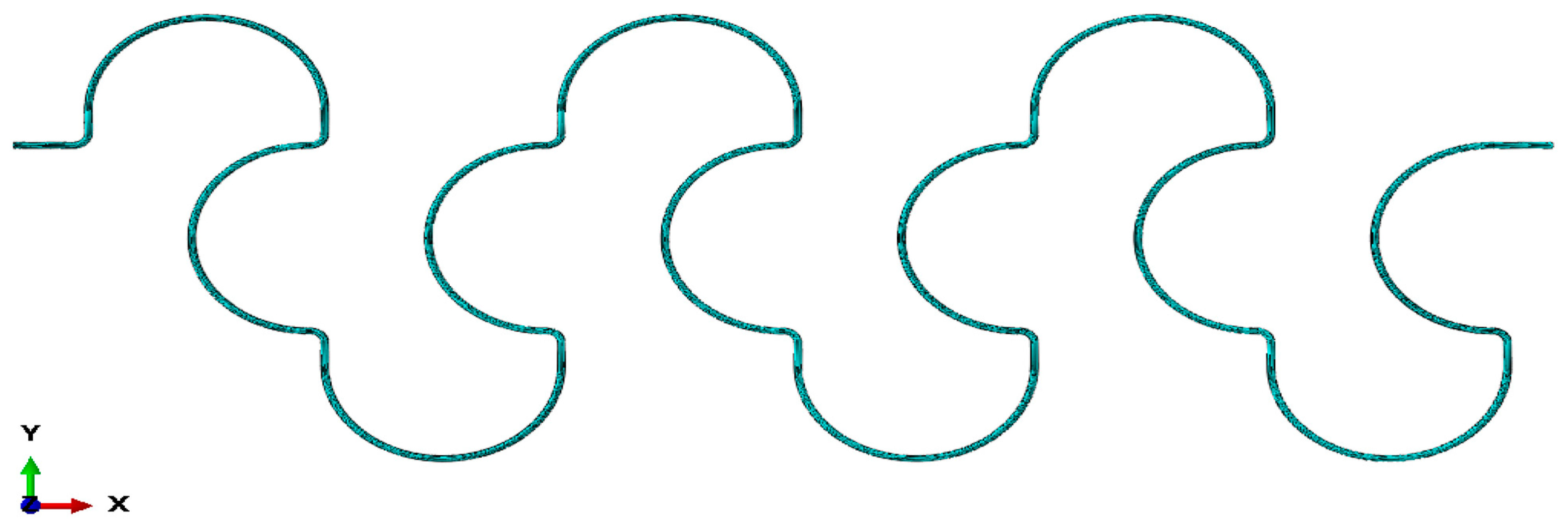
The too small bending radius can weaken the core’s ability to constrain the guided modes, causing some of the core guided modes to transform into cladding modes or radiation modes, and leak to the cladding or even the external environment, thereby increasing fiber bending losses. At the same time, when the light field undergoes total reflection at the interface between the cladding and the external environment and re-couples back to the core region, an echo wall mode is generated. The bending radius is an important structural parameter that determines the stability of surface-bending optical fiber transmission. The flexible substrate model adopts a rectangular thin film structure. The base thickness is set to 0.8 mm. The length is 88 mm. The width is 52 mm, as shown in
Figure 4. The mechanical simulations in
Figure 4,
Figure 5 and
Figure 6 were performed using Abaqus/CAE 2022.
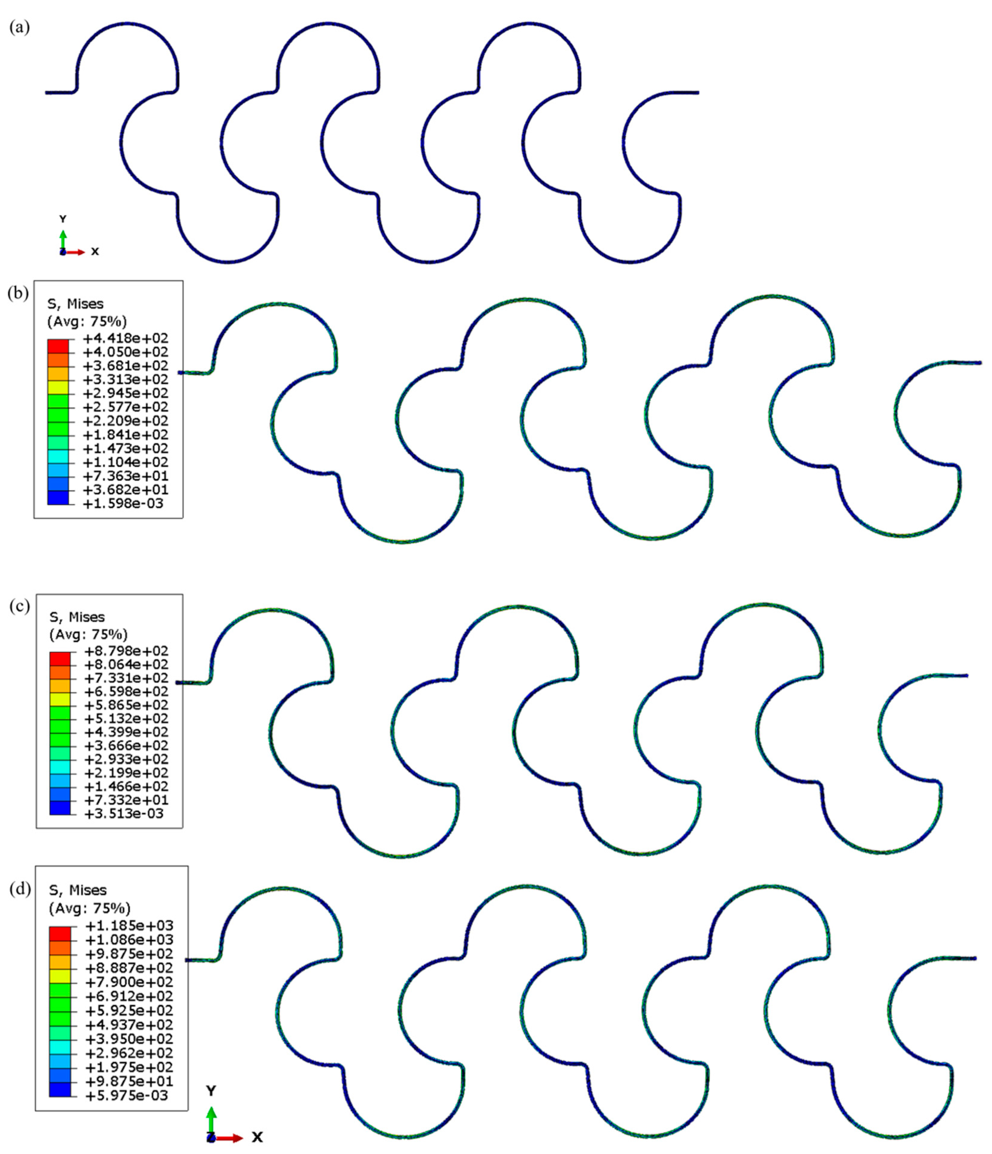
Mechanical simulation was conducted on the sensor in the X-direction. Under the stretching condition in the X-direction, the flexible substrate undergoes in-plane extension along the horizontal direction, and the surface-bent optical fiber undergoes cooperative deformation with the substrate. As the strain in the X-direction gradually increases from the initial state to 10%, 20%, and 30% in the simulation, the overall path of the fiber undergoes significant geometric reconstruction, as shown in
Figure 5. The curved arc corresponding to the horizontally arranged FBG area is gradually stretched and unfolded, and its local curvature continues to decrease. X-directional stretching mainly acts on the bending areas in the fiber path where the tangential direction is close to the X-axis, causing more significant changes in arc length and curvature release in these areas. For FBGs located in laterally sensitive areas, the unfolding of the fiber path will cause changes in their axial strain. The 10%, 20%, and 30% cases are used to visualize the progressive geometric evolution of the fiber path beyond the experimentally investigated 0–10% range; they should not be interpreted as experimental validation to 30% strain. Therefore, the X-direction tensile simulation illustrates the main response tendency of the FBG X-type sensing units to horizontal plane strain.
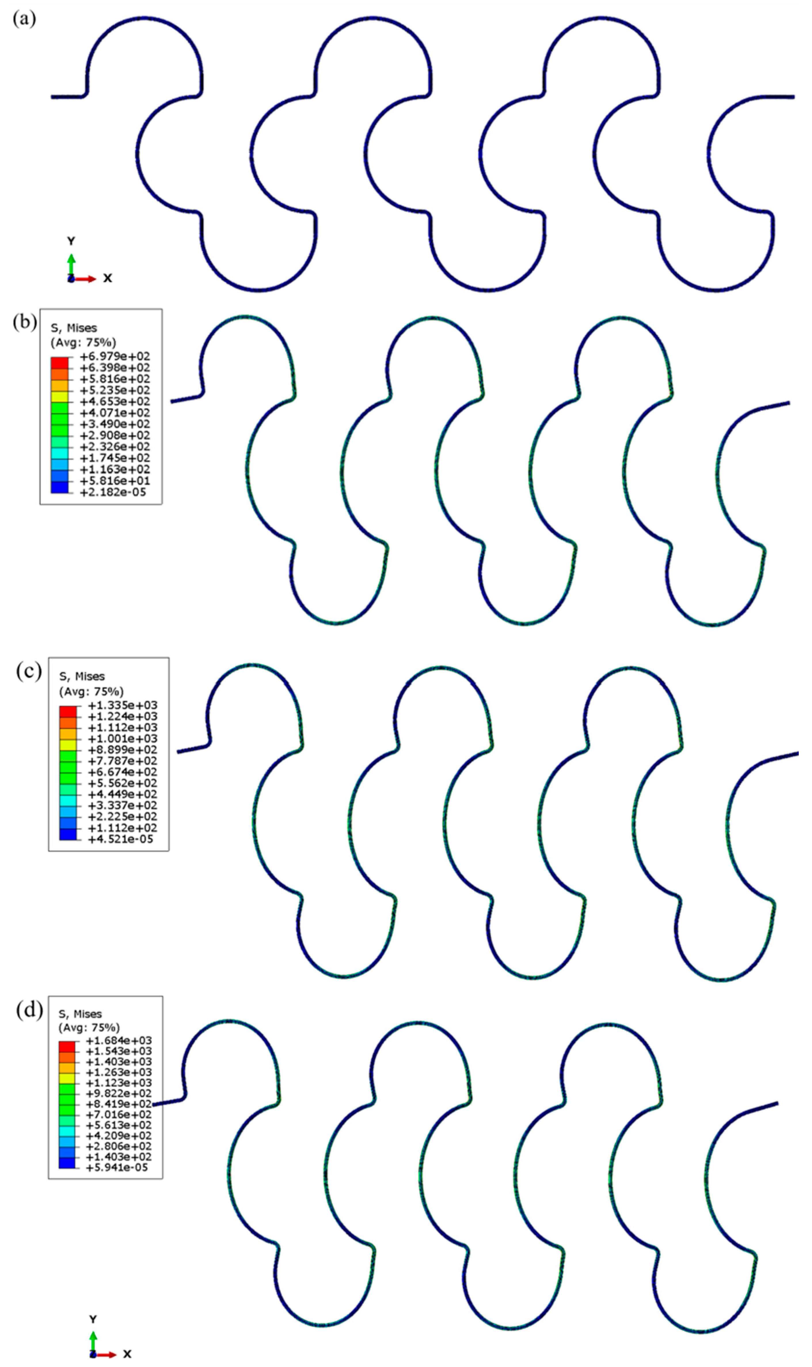
Under the stretching condition in the Y-direction, the flexible substrate undergoes in-plane extension along the vertical direction. As the tensile strain gradually increases, the fiber bending section corresponding to the longitudinal sensitive area undergoes significant unfolding, and the curvature at the location of the FBG continuously decreases. Unlike loading in the X-direction, which mainly affects the transverse FBG region, stretching in the Y-direction has a stronger modulation effect on the longitudinally arranged FBG region, as shown in
Figure 6.
3. Manufacturing of Sensors
A PDMS/SiO2 mixed flexible substrate was prepared by the solution casting method. PDMS (Dow Corning, USA) main agent, PDMS curing agent, and SiO2 particles (Macklin, Shandong Province, China) with a particle size of 2 μm were added into the beaker in a mass ratio of 10:1:1.22. This ratio ensures that PDMS is fully cross-linked to form a flexible elastic network, while improving the mechanical stability and anti-hysteresis ability of the substrate through the filling and reinforcement effect of SiO2 particles. After the mixture is prepared, it is mechanically stirred directly in the beaker using an electronic mixer (Shanghai XIUILAB Instrument Co., Ltd.Shanghai, China). Stir at a speed of 200 rpm for 2 h to fully disperse SiO2 particles in the PDMS prepolymer system. Subsequently, reduce the speed to 100 rpm and continue stirring for 2 h to further improve mixing uniformity while reducing the introduction of bubbles during high-speed stirring.
Slowly inject the PDMS/SiO
2 mixture that has been stirred into the processed PMMA film mold. The mold is a PMMA square plate with a length of 100 mm, a width of 100 mm, and a thickness of 3 mm. The central area is machined with a rectangular groove with a length of 88 mm, a width of 82 mm, and a depth of 0.9 mm. During the injection process, rapid tilting should be avoided to reduce the generation of large-sized bubbles. After injecting the mixed solution into the mold, let it stand at room temperature for 4 h to allow the bubbles introduced during stirring and casting to fully float and escape.
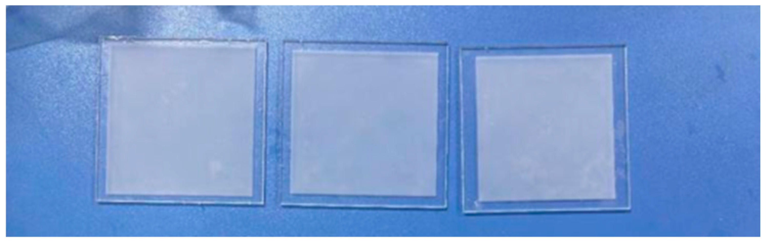
Figure 7 shows the process of preparing thin films.
After settling, place the mold in a high-temperature oven for thermal curing, with a curing temperature of 80 °C and a curing time of 60 min. After curing, let the mold cool naturally to room temperature. After the film is completely cooled, use a blade to gently separate the film from the mold along the edge of the mold to complete demolding. Finally, a PDMS/SiO2 hybrid flexible film with a thickness of approximately 0.9 mm is obtained. This film combines the high deformation capability of PDMS with the mechanical stability enhanced by SiO2 particles, making it a flexible substrate for surface-bonded curved FBG arrays. The FBG array dust collection is bonded with epoxy resin adhesive. During the pasting process, direct pressing of the FBG grid area should be avoided to avoid introducing local residual stress or causing spectral distortion. For the semi-circular curved section, it should be ensured that the optical fiber is consistent with the depicted path, and the four FBGs should be located in the sensitive areas of the design. After pasting, let the sensor stand at room temperature until the epoxy resin adhesive is fully cured. During the curing process, the film should not be moved, or the optical fiber should not be pulled, to avoid introducing initial pre-strain during the formation of the adhesive layer. The actual film dimensions are 88 × 82 × 0.9 mm, corresponding to the mold cavity. Film length affects the available gauge length and fiber-path layout, while width and thickness influence lateral constraint, flexibility, and deformation transfer to the bonded fiber. At a fixed clamp displacement, a longer gauge produces a smaller nominal strain. These effects also depend on bonding and clamping conditions; no comparison among different film sizes was performed.
The sensor preparation process has a significant innovation. PDMS/SiO
2 substrate is formed by mold casting, with controllable thickness and size. The introduction of SiO
2 particles is intended to modify the mechanical properties of the PDMS substrate. However, a direct pure-PDMS control experiment is not included in the present study, so the effect of SiO
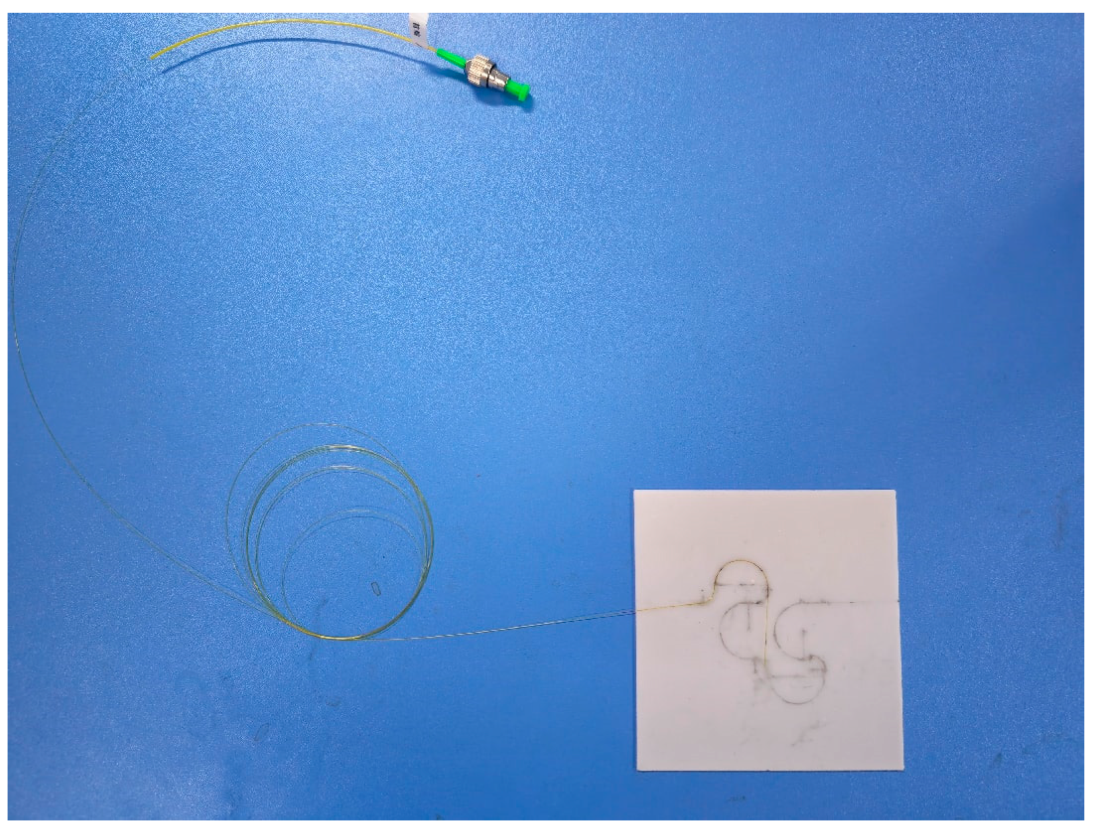
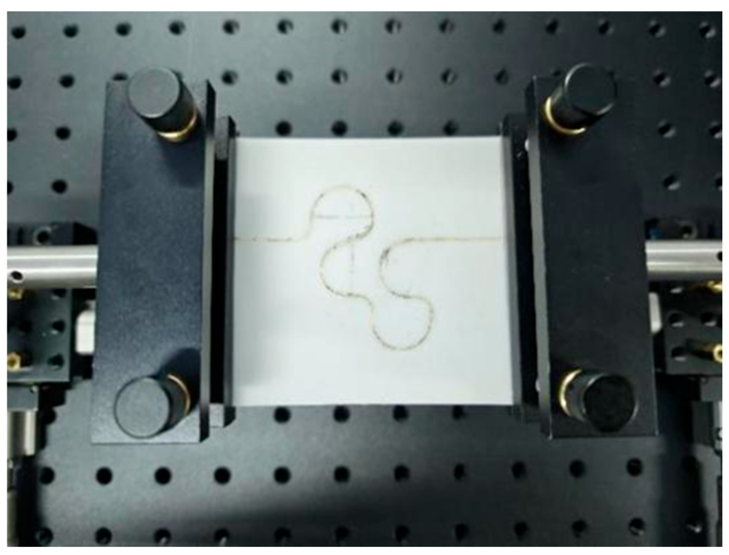
2 on hysteresis is not quantitatively established. The surface adhesive integration method avoids damage to the integrity of the film structure caused by slotting processing. The epoxy resin adhesive point bonding process can ensure a strong bond between the optical fiber and the substrate while reducing the thickness of the adhesive layer, allowing the sensor to maintain good flexibility and strain transmission capability. The sensor sample is shown in
Figure 8.
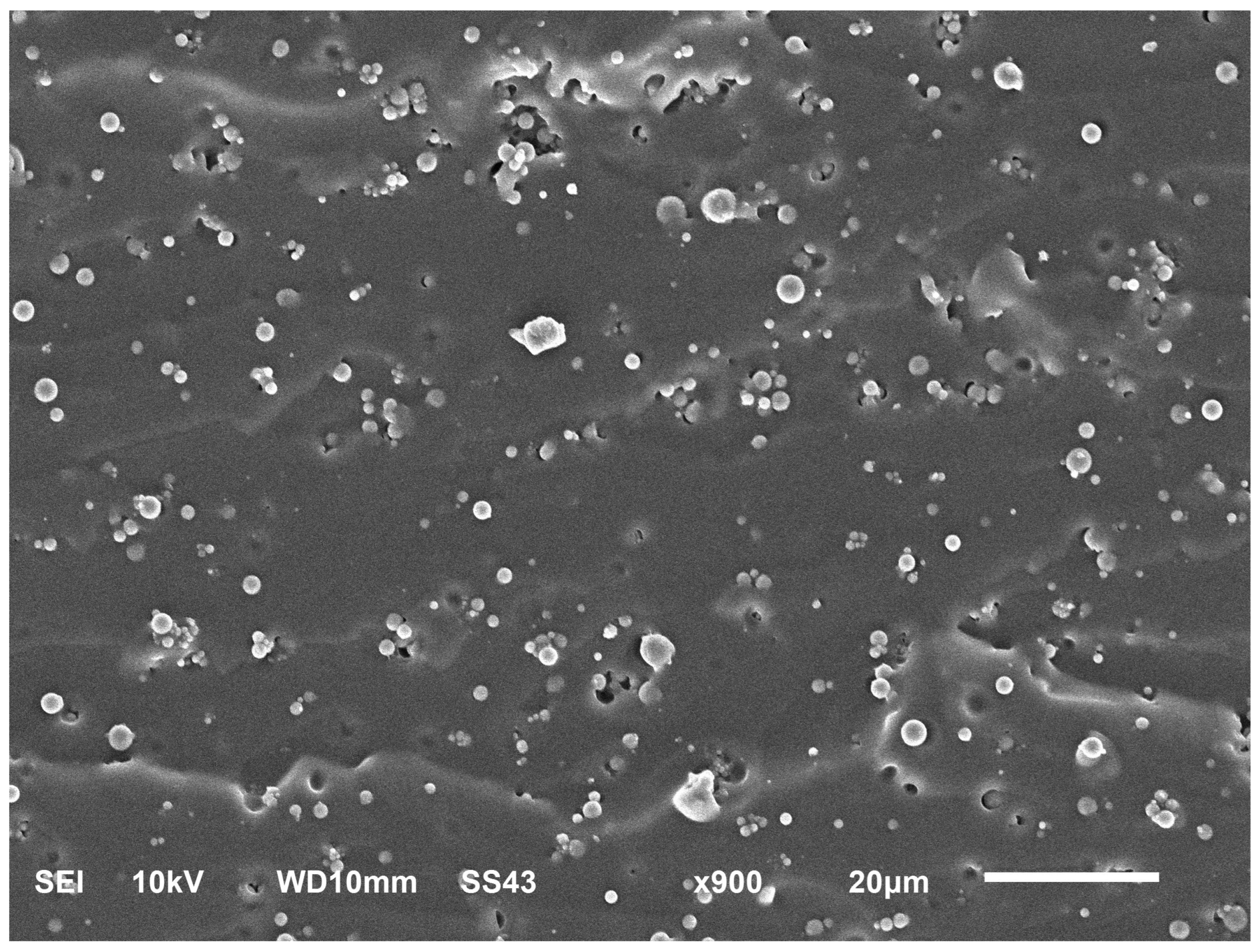
To further characterize the surface microstructure of the PDMS/SiO
2 hybrid flexible substrate and the dispersion state of SiO
2 particles in the PDMS matrix, scanning electron microscopy (SEM) (China) was used to observe the morphology of the cured composite film. The overall surface of the film is relatively continuous, without obvious through cracks or large-sized pores, indicating that the use of solution casting and heat curing processes can obtain a structurally intact flexible substrate. SiO
2 particles can be well dispersed in the PDMS matrix, and no severe large-scale agglomeration phenomenon was observed, as shown in
Figure 9. The introduction of particles transforms the surface of the film from a relatively smooth morphology of pure PDMS to a composite surface structure with local micro-protrusions. This microstructure provides local mechanical reinforcement of the PDMS matrix. A quantitative reduction in viscoelastic relaxation or hysteresis relative to pure PDMS cannot be established without a corresponding control experiment.
4. Experimental Testing of Sensor Sensing Characteristics
To verify the strain response capability of the two-dimensional flexible large-strain FBG sensor in the orthogonal direction, a thin-film tensile experimental platform based on a two-dimensional displacement table was built, as shown in
Figure 10. The platform mainly consists of a two-dimensional manual displacement table, a thin-film fixture, a raised extension connection structure, and a fixed base, used to apply quasi-static displacement loading to PDMS/SiO
2 hybrid substrate flexible sensors. During the experiment, the reflected wavelength signals of the last two FBGs were synchronized with the first two FBGs, so strain analysis was mainly based on the changes in the center wavelength of FBG1 and FBG2. FBG1 corresponds to the X-direction sensitive unit, denoted as FBGx1. FBG2 corresponds to the Y-direction sensitive unit, denoted as FBGy1. The sensor sample is fixed in the thin-film fixture of the displacement table stretching platform, and the fixture is driven by rotating the micrometer to generate relative displacement, thereby applying in-plane tension to the PDMS/SiO
2 mixed film. For both loading directions, the initial clamp separation was L
0 = 70 mm, and the engineering strain was ε (%) = 100ΔL/L
0, where ΔL is the relative clamp displacement. The strain tests were performed at constant temperature. The interrogator wavelength resolution and sampling frequency were 1 pm and 1 Hz, respectively.
The 10% upper test limit corresponds to the limit of the current sensor packaging process. Further extension would require improvements in packaging and verification of the remaining fiber-path unfolding capacity, allowable local fiber strain, bending loss, adhesive slip or debonding, and reliable reflection-peak tracking. Relaxation and hysteresis may restrict the usable calibrated range before rupture. The simulations at higher deformation do not establish a larger experimentally verified measurement range.
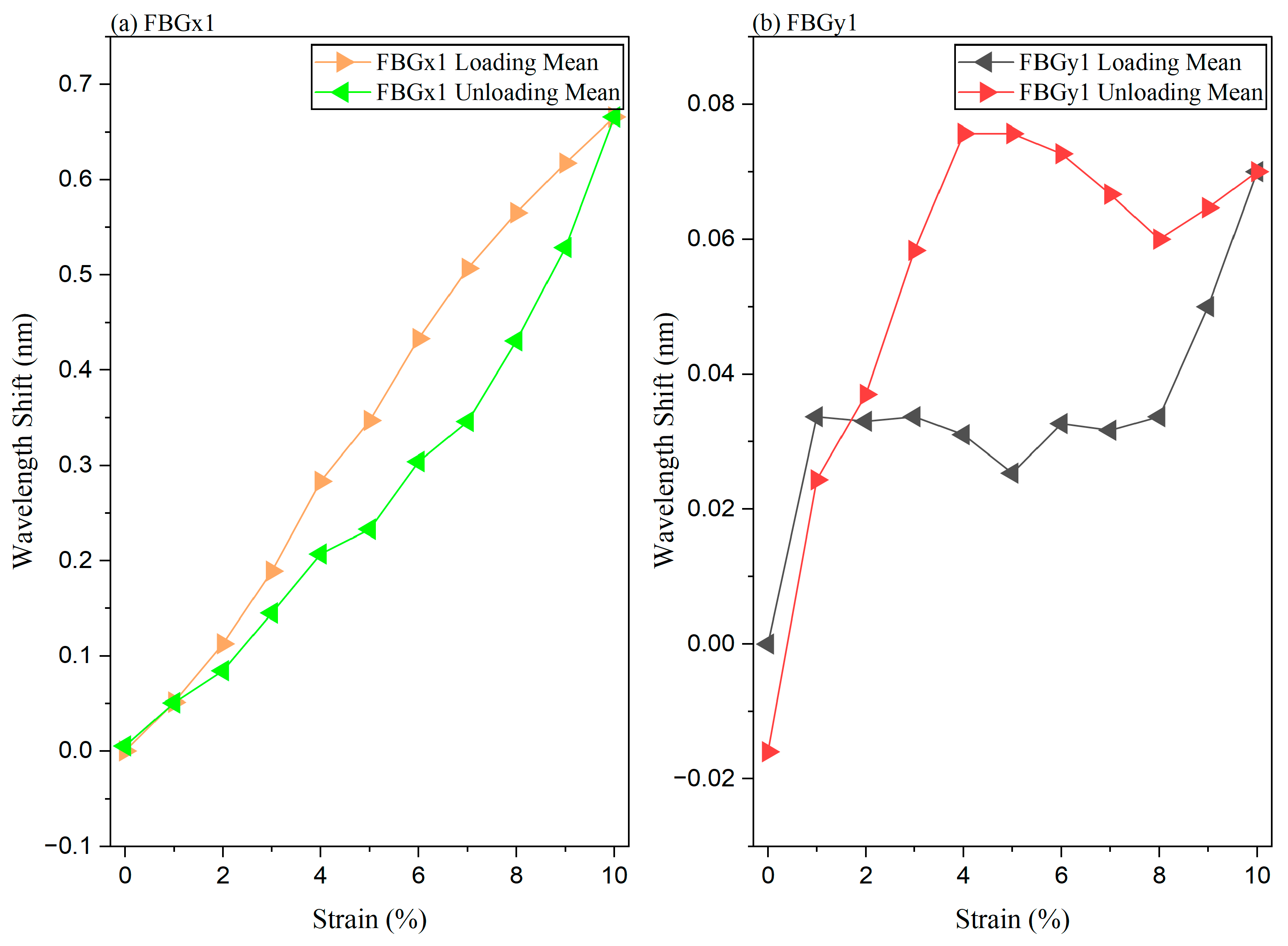
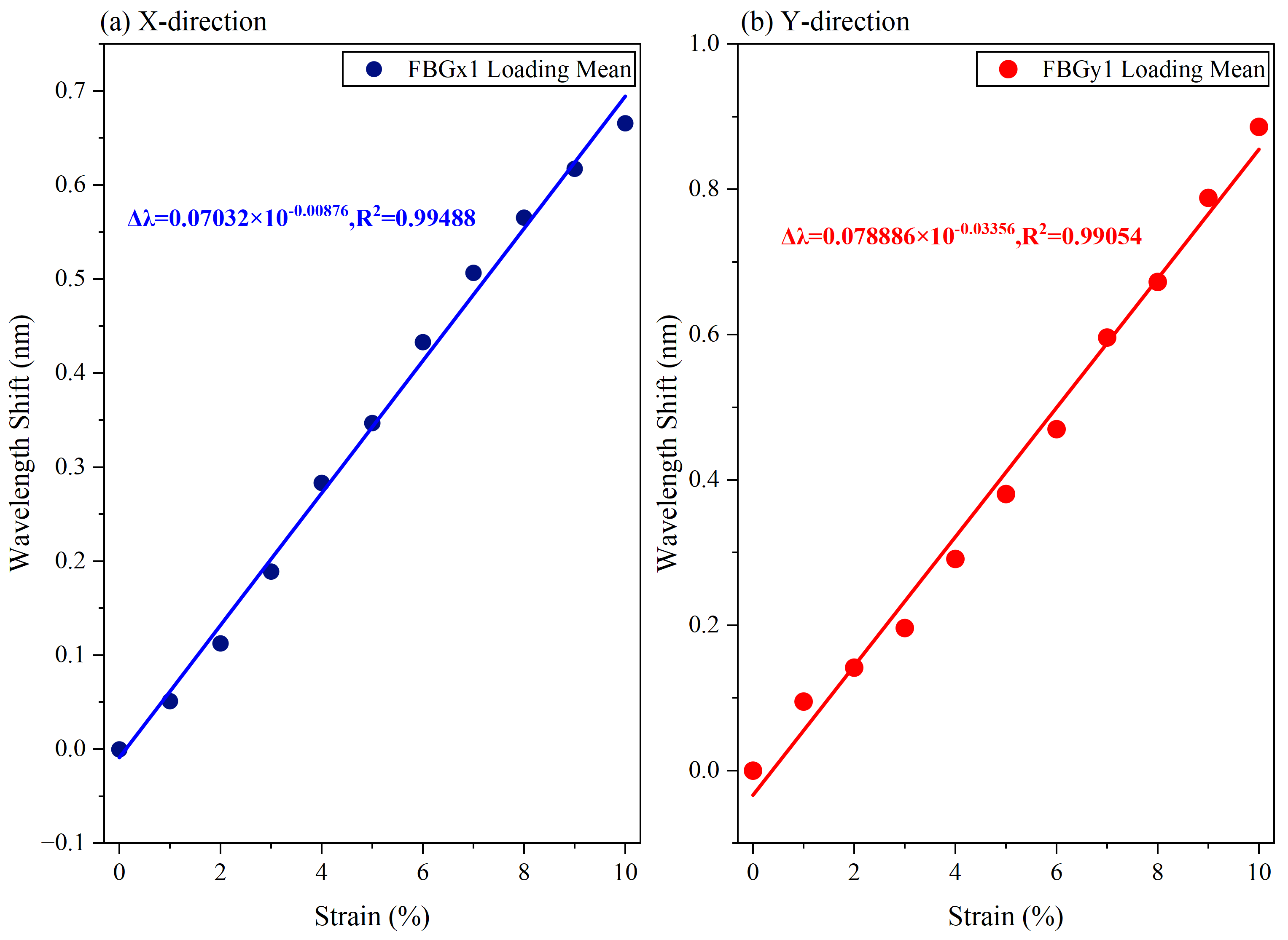
In the X-direction cyclic test, the sensor is gradually stretched along the X-direction with a step size of 1% strain. Load from the initial state to 10% strain, and then gradually unload to the original length with the same 1% strain step size. The complete loading/unloading process is repeated three times to evaluate the sensitivity, linear fitting quality, hysteresis, and cycle-to-cycle repeatability of the sensor in the X-direction. The Y-direction cyclic testing method is consistent with the X-direction, only adjusting the stretching direction to the Y-direction. During the experiment, the FBG demodulator recorded the center wavelengths of the available FBGx1 and FBGy1 in real time, as shown in
Figure 11a,b. During the stretching process in the X-direction, the wavelength drift of FBGx1 changes significantly with increasing strain, exhibiting good monotonicity and an approximate linear relationship, indicating that FBGx1 can effectively respond to the strain of the thin film in the X-direction. FBGy1 also exhibits a measurable wavelength response under X-direction loading, indicating cross-axis coupling. There is a certain difference between the loading and unloading curves, which may arise from the viscoelastic recovery of the PDMS/SiO
2 flexible substrate, the geometric recovery process of the fiber bending path, and the slight relaxation of the bonding interface.
Figure 11b is the cross-axis response of FBGy1 under X loading. Its non-monotonic behavior beyond 4% cannot be used as an independent linear X-strain calibration. It does not negate the principal-channel response measured over 0–10%, but limits a single linear calibration for both directions throughout loading and unloading. Because this cross-axis signal is small, changes caused by relaxation and interfacial strain transfer are large relative to the signal; their individual contributions were not isolated.
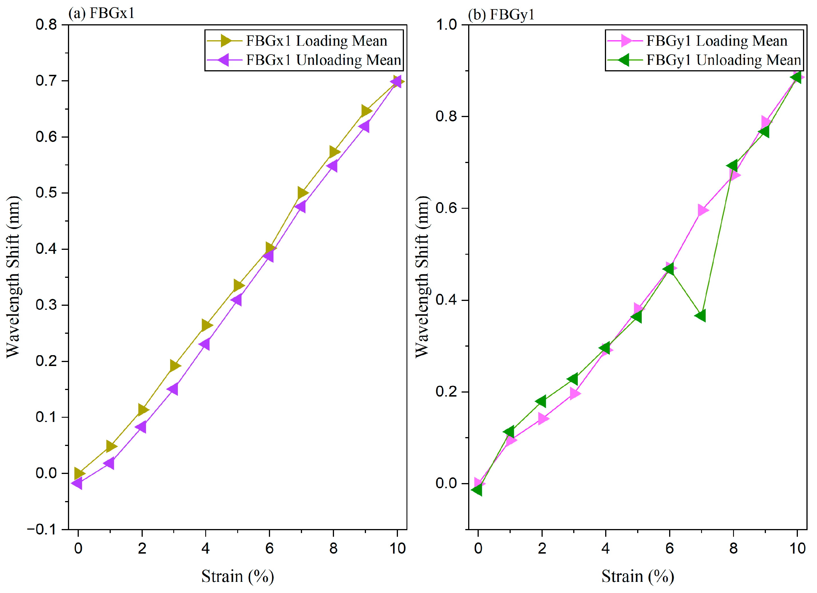
During the stretching process in the Y-direction, FBGy1 exhibits a significant wavelength drift response, and FBGx1 also shows a significant and approximately linear wavelength drift response. Therefore, the response of FBGx1 to Y-direction strain should not be treated as a weak or negligible cross response. This behavior is mainly related to the geometric coupling of the surface curved fiber path. Although the main sensitive direction of FBGx1 is in the X-direction, it is located in a continuous curved fiber path. When the sensor is stretched in the Y-direction, the in-plane deformation of the PDMS/SiO
2 film will cause the entire semi-circular fiber path to undergo collaborative geometric reconstruction, including local corner changes, arc length changes, and curvature release. Therefore, the region where FBGx1 is located will still generate axial strain, leading to wavelength drift, as shown in
Figure 12a,b.
The 7% unloading point in
Figure 12b was checked against the original records. The first-cycle FBGy1 wavelength is 1539.644 nm, giving a shift of 0.034 nm from its initial 1539.610 nm value. Together with the second- and third-cycle shifts of 0.508 and 0.557 nm, the three-cycle mean is 0.366333 nm, consistent with the plotted value. Slip or a peak-tracking disturbance is possible but unconfirmed. The point is retained; repeat measurement and independent peak verification are needed before precise unloading measurements can be claimed.
PDMS/SiO
2 flexible substrate has a high Poisson’s ratio. When stretched in the Y-direction, it will be accompanied by transverse shrinkage and in-plane strain coupling, so the local surface strain field is not distributed in a single direction. Because the fiber and the film surface are closely bonded through the adhesive layer, the two-dimensional deformation of the film will be transferred to the fiber path together. Therefore, the response of FBGx1 to Y-direction strain is reasonable and represents cross-axis coupling of the surface-bonded bent fiber structure. The four measured uniaxial responses are used to construct the full 2 × 2 sensitivity matrix and, in principle, the two strain components can be recovered by matrix inversion. However, because the present experiments are uniaxial and sequential, simultaneous X–Y loading is still required to experimentally validate the complete two-dimensional vector reconstruction, as shown in
Figure 13a,b.
The interrogator wavelength resolution is 1 pm (0.001 nm). The nominal strain-resolution estimate is δε = 0.001/|S| in %, where S is the relevant calibrated sensitivity in nm/%. This instrument-based estimate does not include hysteresis, drift, or calibration uncertainty. The 1% strain steps used here do not establish the minimum experimentally resolvable strain.
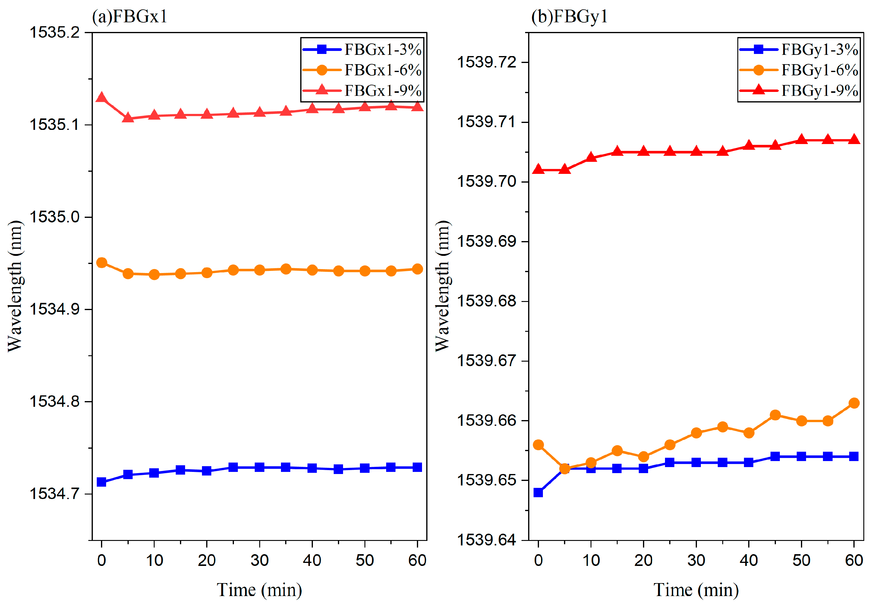
In addition to cyclic tensile testing, constant strain stability experiments were further conducted to evaluate the output stability of the sensor under long-term strain holding conditions. In the stability test in the X-direction, fixed strains of 3%, 6%, and 9% were applied using a displacement table and maintained at each strain level for 1 h. The center wavelengths of FBGx1 and FBGy1 were recorded every 5 min. The stability testing method in the Y-direction is the same, only changing the stretching direction. In the experiment of maintaining constant strain in the X-direction, the wavelength drift of FBGx1 gradually increases as the strain level increases from 3% to 9%, indicating its ability to distinguish different amplitudes of X-direction strain. At each fixed strain level, the wavelength of FBGx1 only fluctuates slightly over time and does not show significant sustained drift. This indicates that the sensor has good stability under X-direction loading, as shown in
Figure 14a,b. In
Figure 14b, the mean FBGy1 wavelengths at 3% and 6% X strain are 1539.652615 and 1539.657308 nm, respectively, separated by only 4.69 pm with overlapping observed ranges. Their proximity is consistent with the weak, non-monotonic cross-axis response in
Figure 11b. Thus, FBGy1 alone does not reliably distinguish these two X-strain levels; FBGx1 provides the principal X-direction response.
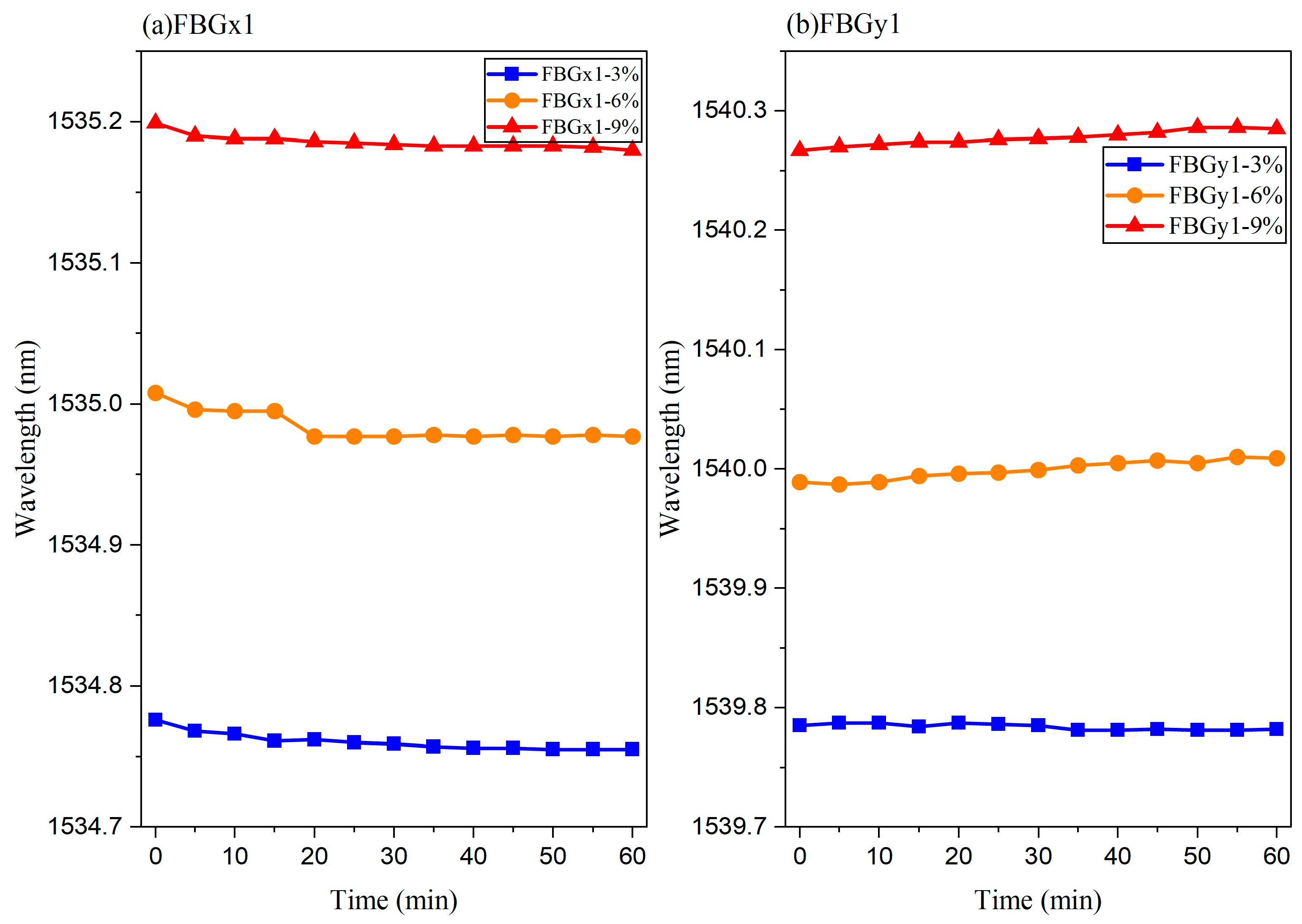
In the constant strain maintenance experiment in the Y-direction, FBGy1 exhibits similar stable output characteristics. As the Y-direction strain increases from 3% to 9%, the wavelength drift of FBGy1 gradually increases. During the 1-h holding process, the wavelength curves at various strain levels remained relatively stable, with only slight random fluctuations. This result indicates that the sensor also has good long-term output stability under the stretching state in the Y-direction, as shown in
Figure 15a,b.
Based on the experimental results of comprehensive cyclic stretching and constant strain maintenance, it can be concluded that FBGx1 and FBGy1 are capable of producing stable and reproducible wavelength responses to strain in the X- and Y-directions, respectively. The sensor exhibits good linear response and cyclic repeatability within a large strain range of 0–10%. Stable output was maintained under constant strain conditions of 3%, 6%, and 9%, demonstrating that the two-dimensional flexible FBG sensor based on a PDMS/SiO2 hybrid substrate and surface curved fiber structure has a good ability to monitor large strains.
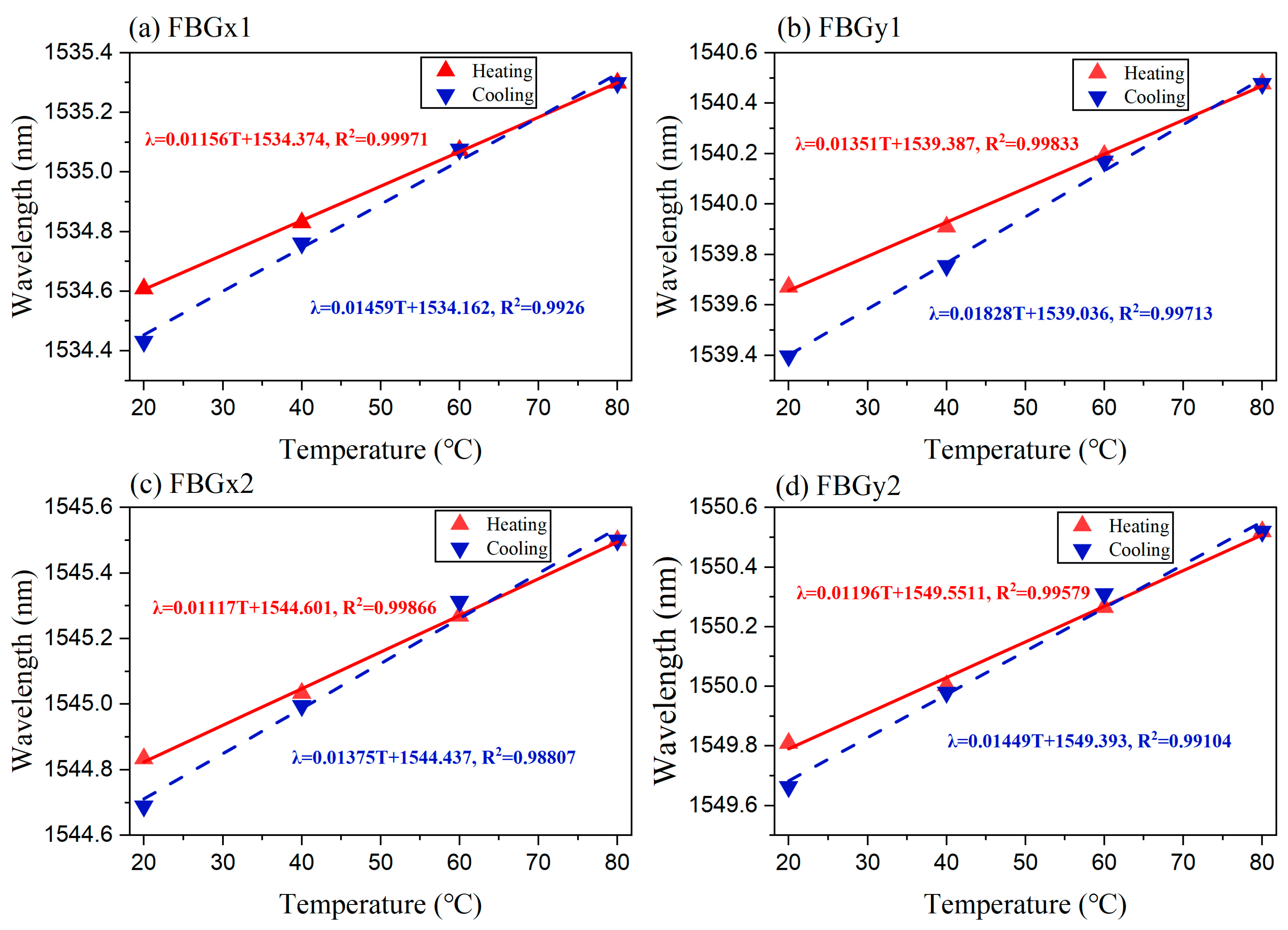
To evaluate the temperature response characteristics and temperature cycling stability of a two-dimensional flexible large-strain FBG sensor, a constant temperature chamber (built in-house by the School of Physics and Optoelectronic Engineering, Beijing University of Technology, Beijing, China.) was used to conduct temperature rise and fall cycling experiments on the sensor. During the experiment, the sensor sample was placed flat and fixed in a constant temperature chamber to avoid additional effects on the FBG wavelength caused by external mechanical stretching or bending disturbances. The sensor input is connected to the FBG demodulator, which real-time collects the center wavelengths of four FBGs, FBGx1, FBGy1, FBGy2, and FBGx2. The initial ambient temperature for the experiment is 17.6 °C. Firstly, raise the temperature of the constant temperature chamber to 20 °C, and use 20 °C as the starting point for temperature cycling testing. Subsequently, raise the temperature in steps of 20 °C to 40 °C, 60 °C, and 80 °C, and record the center wavelengths of the four FBGs at each temperature point. After the heating process is completed, turn off or reduce the heating output of the constant temperature box, allowing the sensor to naturally cool down with the constant temperature box, and record the center wavelengths corresponding to 80 °C, 60 °C, 40 °C, and 20 °C in steps of 20 °C.
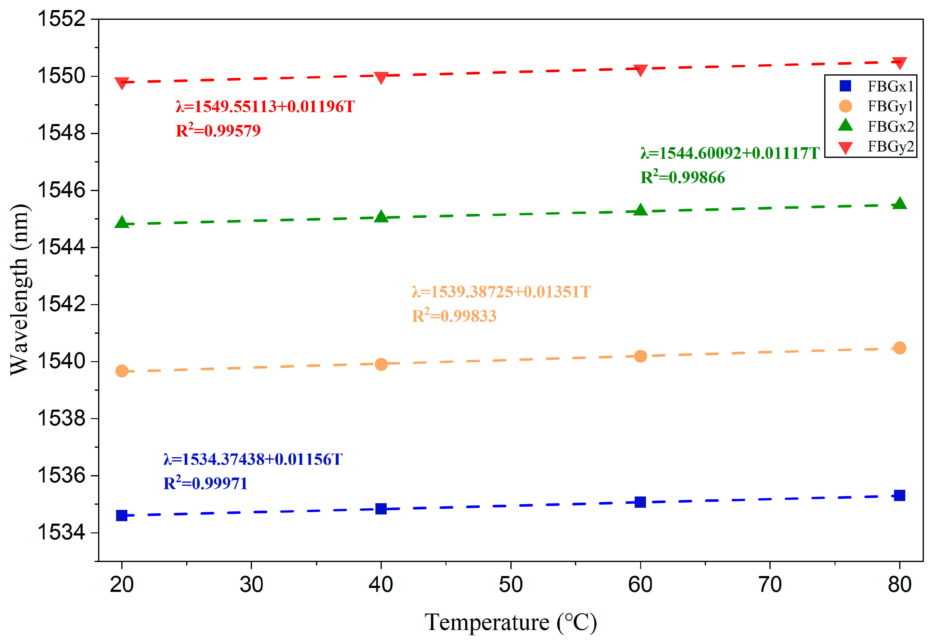
Figure 16 shows the temperature response curves of four FBGs during the heating process from 20 to 80 °C. As the temperature increases, the center wavelengths of FBGx1, FBGy1, FBGy2, and FBGx2 all undergo a red shift, indicating that an increase in temperature will cause changes in the FBG period and effective refractive index, resulting in an increase in wavelength. After linear fitting of the heating process, the temperature sensitivities of FBGx1, FBGy1, FBGx2, and FBGy2 were 0.01156 nm/°C, 0.01351 nm/°C, 0.01117 nm/°C, and 0.01196 nm/°C, respectively. The corresponding linear fitting coefficients R2 are 0.99971, 0.99833, 0.99866, and 0.99579, respectively. A higher R2 indicates that all four FBGs have a good linear temperature response in the range of 20–80 °C.
Figure 17a–d further illustrates the temperature cycling response of the sensor during the heating and natural cooling processes. It can be seen that the center wavelengths of the four FBGs gradually decrease with decreasing temperature during the cooling process, and the overall trend of change is consistent with the heating process. There is a certain difference between the heating curve and the cooling curve, which is mainly related to the thermal expansion/contraction process of the PDMS/SiO
2 composite substrate, the thermal hysteresis of polymer materials, and the release of thermal stress at the fiber/substrate interface. Some differences in temperature sensitivity among the four FBGs are mainly due to different initial center wavelengths of FBGs, different local positions of each FBG in the bending path, differences in local bonding states between the fiber and PDMS/SiO
2 substrate, and uneven distribution of local thermal stress generated by flexible substrates during temperature changes. Due to the significantly higher thermal expansion coefficient of PDMS material compared to quartz fiber, the thermal expansion of the substrate during the heating process will transfer additional thermal strain to the surface fiber through interface interaction, resulting in a higher temperature response of the encapsulated FBG than the intrinsic thermal optical response of the bare FBG. This phenomenon also indicates that in subsequent strain measurements, temperature changes will have a cross effect on the wavelength of the FBG. Therefore, if the sensor is applied in a non-constant temperature environment, temperature compensation needs to be combined with temperature response experimental results. For variable-temperature operation, a nearby thermometer or a mechanically isolated, thermally coupled reference FBG can provide an independent temperature measurement. The calibrated thermal shift of each packaged sensing FBG can then be subtracted before strain inversion: ε = K
−1(Δλ − kTΔT), where kT contains the sensing gratings’ temperature coefficients. Calibration should reproduce the mounting conditions and heating or cooling history because the two thermal branches differ. This is a proposed compensation approach; compensated strain accuracy was not tested here.
For buildings or bridges, multiple sensor patches could be attached at selected locations and connected by optical leads for wavelength-multiplexed interrogation. Peak spacing and optical power margins must accommodate strain and temperature shifts, bending loss, and the number of gratings. Reliable strain transfer, protective packaging, and temperature referencing are required at each patch. Patch spacing and gauge length determine spatial resolution. Field use also requires validation of small-strain sensitivity, cyclic durability, and installation repeatability; the present 1 Hz quasi-static tests do not establish dynamic structural-monitoring performance.
5. Discussion
The combination of a deformable PDMS/SiO
2 film and an orthogonally arranged curved fiber path provides a mechanical route to large-strain FBG sensing. The film accommodates the imposed deformation, while changes in the fiber-path geometry allow the sensing fiber to follow that deformation. The progressive unfolding illustrated in
Figure 5 and
Figure 6 is consistent with this interpretation and helps explain how measurable grating responses can be obtained over the tested 0–10% film-strain range. This links the structural design to the experimental response: the strain imposed between the clamps is redistributed along the curved path before reaching the grating regions. The simulations provide qualitative support for this mechanism, rather than a quantitative calibration of the fabricated specimen.
The contribution can be placed in the context of two related approaches. Liu et al. [
27] combined a polarization-maintaining fiber and an FBG in a Sagnac interferometer to extend the measurable range beyond a free-spectral-range limitation. The present design addresses mechanical accommodation of large substrate deformation through the fiber geometry. The approaches, therefore, act on different constraints, and their sensitivities must be compared with attention to the strain applied to the actual sensing element. Reference [
28] provides a closer structural comparison through its PDMS/SiO
2-supported FBG array. Building on this class of flexible substrate, the present work examines an orthogonal arrangement and characterizes the principal and cross-axis responses under two loading directions. This identifies the directional behavior of the integrated structure as the focus of the contribution.
The different responses under X and Y loading reveal how local orientation and the continuity of the fiber path act together. FBGx1 provides a pronounced response under X loading, while FBGy1 responds strongly under Y loading. However, the substantial FBGx1 response to Y loading and the weaker, non-monotonic FBGy1 response to X loading show that the two directions are not mechanically independent. Transverse substrate deformation and redistribution of strain along the bonded curved fiber are plausible contributors to this asymmetry. These observations motivate retaining the cross-axis coefficients in the sensitivity matrix and selecting a calibration interval that represents the measured behavior. The uniaxial experiments establish the directional response patterns; simultaneous biaxial tests are the next step for evaluating reconstruction of combined strains.
The cyclic and strain-holding experiments provide complementary information about calibration and signal retention. The principal loading curves have reported R
2 values of 0.99488 and 0.99054, supporting an approximately linear calibration of the mean loading responses. The separated loading and unloading branches indicate that deformation history also affects the output, consistent with possible viscoelastic recovery and interfacial relaxation. During the one-hour holds, the principal-channel traces at the tested strain levels remain distinguishable, supporting the use of these channels for monitoring sustained deformation under the test conditions. The nearby cross-axis traces in
Figure 14b reinforce the need to interpret each channel according to its directional response. Together, the experiments support branch-specific calibration and sustained-strain monitoring, while the anomalous unloading point and the limited number of cycles warrant further repeatability testing.
The temperature measurements characterize another part of the strain-transfer process in the packaged sensor. The approximately linear heating responses, with sensitivities of 0.01117–0.01351 nm/°C, provide a basis for estimating thermal wavelength shifts. Differences among the gratings and between heating and cooling suggest that local packaging conditions and thermal history should be considered in calibration. Luo et al. [
20] used heterogeneous waveguide Bragg gratings with distinct thermal responses to discriminate temperature and strain. In the present sensor, the flexible substrate serves the mechanical objective of accommodating deformation, so its thermally induced strain transfer must also be included when developing compensation. An independent temperature reference and calibration representative of the mounted sensor offer a practical direction for extending the present constant temperature strain tests to changing environments.
The results therefore support a design strategy that combines large deformation accommodation with characterization of direction-dependent wavelength responses in a flexible sensor patch. They also identify concrete priorities for further development: controlling strain transfer at the bonded interface, calibrating loading-history effects, and evaluating combined mechanical and thermal inputs. The 10% range is the experimentally investigated limit of the current package; neither the larger simulated deformations nor the 1 pm interrogator resolution independently establishes a wider calibrated range or a minimum detectable strain. Further work on biaxial loading, durability, and interrogation of multiple patches would determine how this structure can be translated from the present laboratory characterization to distributed measurements on deformable surfaces.