Review

Recent Progress in Development of Hollow-Core Fibers for Telecommunications and Data Transmission Applications


by
Krzysztof Borzycki
National Institute of Telecommunications, ul. Szachowa 1, 04-894 Warsaw, Poland
Photonics 2026, 13(5), 494; https://doi.org/10.3390/photonics13050494
Submission received: 16 February 2026 / Revised: 1 April 2026 / Accepted: 23 April 2026 / Published: 15 May 2026

Abstract

The progress made in several fields after 2023 is rather significant. Attenuation achieved by the best HCFs was reduced to 0.05–0.10 dB/km at 1550 nm, while the lowest attenuation achieved in a single-mode fiber with a pure silica core equals 0.14 dB/km. Polarization mode dispersion (PMD) has been reduced to a level typical of SMFs, through fiber spinning. In November 2024, Microsoft announced a 2-year plan to install 15,000 km of HCF cables between and within data centers processing data for Microsoft Azure cloud services. Furthermore, several HCF manufacturers have emerged: UK-based Microsoft Azure Fiber and two Microsoft subcontractors, namely Corning Inc. and Heraeus Covantics, plus two major HCF manufacturers in China, YOFC and Linfiber. Additionally, extensive work was carried out on optical amplifiers to enable new transmission bands in HCFs, both at short wavelengths (≈1300–1500 nm), with bismuth-doped active fibers, and long wavelengths (≈1700–2100 nm), with thulium- and holmium-doped fibers. On the other hand, progress in HCF standardization, splicing and elimination of loss bands introduced by contaminants, has been marginal. Standardization is blocked by multiple fiber designs being tried, with no clear winner emerging yet. Despite this, hollow-core fibers have been successfully debuted in large-scale commercial data centers and are also used in low-latency data links.

1. Introduction

This study presents a follow-on review of the progress made in the development of hollow-core optical fibers (HCFs) and their applications. It is a continuation of the previous review published in 2023 [1] and should be construed in conjunction therewith.
Single-mode optical fibers made of solid fused silica with dopants have, following their commercial introduction in the NTT network in 1982 and standardization by ITU-T in 1984 [2], gradually became the dominant medium for telecommunication and data transmission networks, mobile backhaul and, to a growing extent, data centers, steadily replacing coaxial and twisted-pair cables in the process. Single-mode fibers have also replaced most microwave radio backhaul links with 4G and 5G mobile radio sites. According to data published by CRU, worldwide consumption of single-mode fibers in 2025 is expected to reach 568 million kilometers [3].
Development and production of telecom fibers during the 1975–2020 period have been essentially limited to fibers made of fused silica, with a single solid core. The fiber’s core and, optionally, some adjacent areas are doped with germania (SiO2) and, discretionally, fluorine (F2). Fibers of this type are mass produced at low cost, with prices in 2025 being reduced to USD 3–4 per km in large contracts concluded in China [4]. They are also simple to install and reliable to operate.
Developments that took place after 2010 brought two fundamentally new classes of telecom/datacom fibers to the threshold of their commercial deployment:
  • Multi-core fibers (MCFs), with several (2, 4, 7, 8, etc.) single-mode cores packed into a common cladding with a spacing of approx. 40–45 μm [5];
  • Hollow-core fibers (HCFs), having a single empty core filled with gas and an optical barrier made of thin-walled glass structures, usually nested tubes [1,6], preventing light from escaping; both this barrier and the cladding are made of undoped fused silica.
Single-mode MCFs offer high density of cores and uniform latency of multiple optical paths in the fiber [5], while their attenuation, cutoff wavelength, chromatic dispersion, optical non-linearities, core dimensions and MFD, etc., are identical to those of single-core single-mode fibers.
In hollow-core fibers, the glass is replaced with gas (or potentially vacuum in the future) as the medium for light propagation, with the interaction between guided radiation and glass being reduced by a factor of 10,000 to 100,000 in a typical NANF (Nested Anti-resonant Nodeless Fiber). Hollow-core fibers filled with gas—usually air with such contaminants as CO2, hydrocarbons, and water vapor—have fundamentally different optical properties than solid fibers made of fused silica. Many of those parameters are advantageous: low loss, latency reduced by a factor of 1.46 with respect to solid-core fibers, wide and tunable optical bandwidth, negligible non-linearity, low chromatic dispersion and scattering. Others, in turn, are disadvantageous: lack of hermeticity, absorption by contaminants, high PMD, and difficult splicing. A review of these subjects is included in the preceding paper [1] and documents referenced there. As a result, HCFs enable dramatic improvements in performance of core and metro DWDM networks: optical bandwidth, link capacity, elimination of non-linear effects, increased power budget and repeater spacing. Other improvements include resistance to ionizing radiation and potential remote powering via dielectric optical fibers.
The rest of this paper is devoted to HCFs, specifically low-loss, low-latency and wideband DNANF fibers developed for telecommunication and data transmission applications.
In the following parts of this paper, Section 2 compares the latency (or velocity of propagation) in various media: air, HCF, solid-core telecom fibers and twisted-pair cables, as low latency is currently the most important advantage of all HCFs.
Section 3 presents the progress in reducing HCF attenuation that has been achieved since 2023 and showcases new low-loss fiber designs. In Section 4, some issues related to HCF manufacturing are presented, including reductions in PMD via fiber spinning and absorption by contaminants. Section 5 explains the potential role of HCFs in telecom and data networking (once these become available at scale) and presents prospects for standardization. Section 6, meanwhile, presents amplifiers for new transmission bands, incorporating active fibers with new dopants: bismuth (Bi), thulium (Tm), and holmium (Ho). Commercial deployment in Microsoft Azure AI infrastructure is covered in Section 7. Section 8 lists miscellaneous technologies and devices required to make full use of HCFs in future networks. Section 9 discusses the findings.

2. Latency in HCF-NANF and Other Transmission Media

Low latency of HCFs is currently their main advantage over all other optical fibers and twisted-pair cables used in data centers and networks.
Relative latency of fibers is proportional to the ratio of effective refractive indices of telecom single-mode fibers conforming to ITU-T Recommendation G.652 [7], G.654 [8], G.657 [9] (neff = 1.46–1.48) or OM3, OM4 or OM5 50/125 μm graded index multimode fibers, covered by TIA-492AAAE [10] and IEC 60793-2-10 [11] standards, used in data centers, servers and LANs (neff = 1.47–1.50), and hollow-core fibers (neff = 1.00–1.01). The communications industry uses a number of latency-related parameters:
  • Effective refractive index (neff)—applicable to optical fibers only;
  • Absolute latency per unit of length, e.g., μs/km;
  • Velocity of propagation (VP), related to the speed of light in vacuum (c);
  • Absolute velocity of propagation (VP), usually in m/μs.
Typical values are presented in Table 1. HCF latency data published are only approximate and presented as a ratio between latencies of HCF and solid-core fused silica fibers (≈1.46) or as latency reduction in an HCF link of the same length (≈31%). The lowest latency is achieved in straight-line microwave or optical links, with propagation in the air (in terrestrial systems) or vacuum (in space systems). However, bit rates and availability are substantially inferior to those of optical fiber links.
A further meaningful reduction in latency in hollow-core fibers is impossible, even when the filler gas is replaced with vacuum.
OM4 multimode fibers and Cat. 7 twisted-pair cables are the latest generations of such products in mass use. The NVP of older Cat. 5e and Cat. 6 UTP twisted-pair cables is lower (0.59–0.70) due to a solid dielectric being used, rather than a foamed one. NVP of a coaxial cable whose dielectric is made substantially of gas pockets may exceed 0.90. Because of the dispersive properties of solid dielectrics, such as LDPE, the parameters given above are wavelength/frequency-dependent; this effect is very weak in gas and insignificant in HCF [1].
One must realize that the actual length of fibers in outdoor links is approx. 3–10% larger than the overall length of the cable route due to the following factors:
  • Fiber overlength in the cable (0.15–4%);
  • Extra lengths of cable due to sag and vertical lengths (3–6%) in aerial networks;
  • Spare lengths of cables adjacent to joint closures (1–2%), etc.
Even larger differences exist, in many cases, between straight-line distance and route length, as available routes are restricted by obstructions (rivers, mountains, etc.) and the existing infrastructure, e.g., cable ducts, and rights-of-way. The same problem exists inside data centers. Careful design of cable routes and installation methods, coupled with avoiding aerial links and long spare lengths, may substantially reduce fiber length and latency.

3. Reduction in HCF Attenuation and New Fiber Designs

Low-loss hollow-core fibers are especially important in networks spanning large areas, with numerous nodes separated by large distances. Such networks have fewer nodes with active equipment requiring buildings or containers and electric power, which results in considerable savings on construction and operation costs (CAPEX, OPEX).
When the previous review paper [1] was written, the lowest loss of a 5-tube NANF was 0.174 dB/km [13] and was comparable to the lowest loss in conventional fibers with a pure silica core (0.144–0.18 dB/km) covered by ITU-T Recommendation G.654 [8]. Data regarding such fibers may be found in Refs. [14,15,16,17,18]. The lowest specified attenuation of a commercially available fiber at 1550 nm was (and still is) 0.144 dB/km in a G.654.D-compliant Sumitomo Z-PLUS Fiber 150 for transoceanic networks [18]. The lowest attenuation achieved in the lab at Sumitomo in 2025 was 0.1397 dB/km at 1566 nm and 0.1406 dB/km at 1550 nm [19,20]. The fiber was similar to the Z-PLUS Fiber 150, with a large mode area (MFD = 13.3 μm, Aeff = 147 μm2); both core and inner cladding were doped exclusively with fluorine in different concentrations. The potential for further progress in reducing the attenuation of solid-core fibers is very limited, but even a 0.002 dB/km reduction with respect to the previous record-breaking fiber made at the same company in 2017 [21] may decrease the cost of transoceanic links, due to the reduction in the number of submerged repeaters by approx. 2%.

3.1. Ultra-Low-Loss DNANF Fibers for Operation at 1550 nm: 2024

Hollow-core fibers of the DNANF type, exhibiting very low attenuation, were developed: one with five truncated nested tubes (5T-DNANF) at the University of Southampton and Microsoft Azure Fiber in the UK [22,23] and one with four truncated nested tubes (4T-DNANF) at Jinan University and Linfiber Technology in China [24], both in 2024. While their attenuation was similar, several details were different, as shown in Table 2 and Figure 1. One difference includes thicker walls (membranes) for the nested tubes used in the Chinese fiber, ≈1.1 μm vs. ≈0.5 μm [22,24], since this fiber is designed to operate in the second NANF transmission window [1] (pp. 11–12). This feature simplifies the production process, as the tubes are stronger and stiffer, but reduces low-loss bandwidth. However, the fiber still exhibits low-loss characteristics (barring gas absorption) in full C and L bands.
The spectral loss of the British fiber is presented and discussed in Section 4.2.
Higher-order mode extinction ratio (HOMER) is the ratio of attenuation for dominant higher-order mode (HOM) and fundamental mode (FM) in a given fiber. A higher HOMER value means superior modal purity of the transmitted signal, a parameter that is important in Fiber Optic Gyroscopes (FOGs) and polarization-based measurement systems but much less so in telecom networks and data centers.

3.2. Truncated Nested Tubes

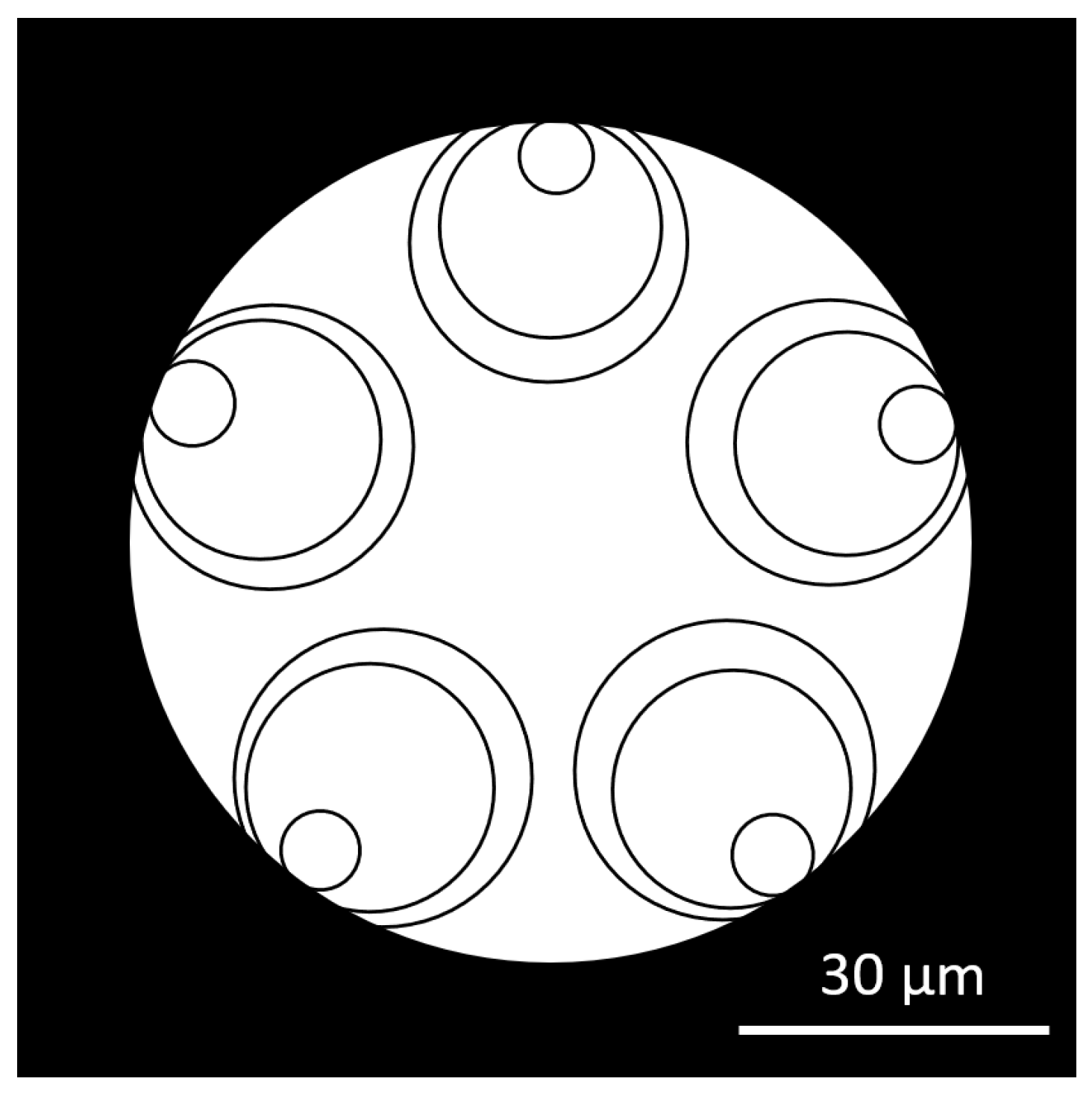
Record low-loss HCFs shared a new feature: nested tubes “truncated” on the side of the jacket tube (Figure 1). This solution was described by researchers from Jinan University, Guangdong, China, in 2024 [25], although significant truncation was already present in early low-loss 5T-DNANFs [13] (Figure 2). It is a byproduct of heating and softening the preform used to draw the fiber. The novelty lies in employing this phenomenon, to a controlled extent, to reduce the fiber microstructure diameter (MSD) and the diameter of cladding (jacket). Truncation of nested tubes away from the fiber’s core has only limited influence on confinement loss of the fiber, as most of the radiation propagating in the fiber is reflected back by the walls (membranes) located close to the core [25].
Truncation is measured in degrees, indicating the angular section of the nested tube sunk into the cladding tube; typical values in ultra-low-loss DNANFs are in the 70–130° range. Larger truncation is detrimental, as it increases confinement loss [25].

3.3. Ultra-Low-Loss DNANF Fibers for Operation at 1550 nm: 2025

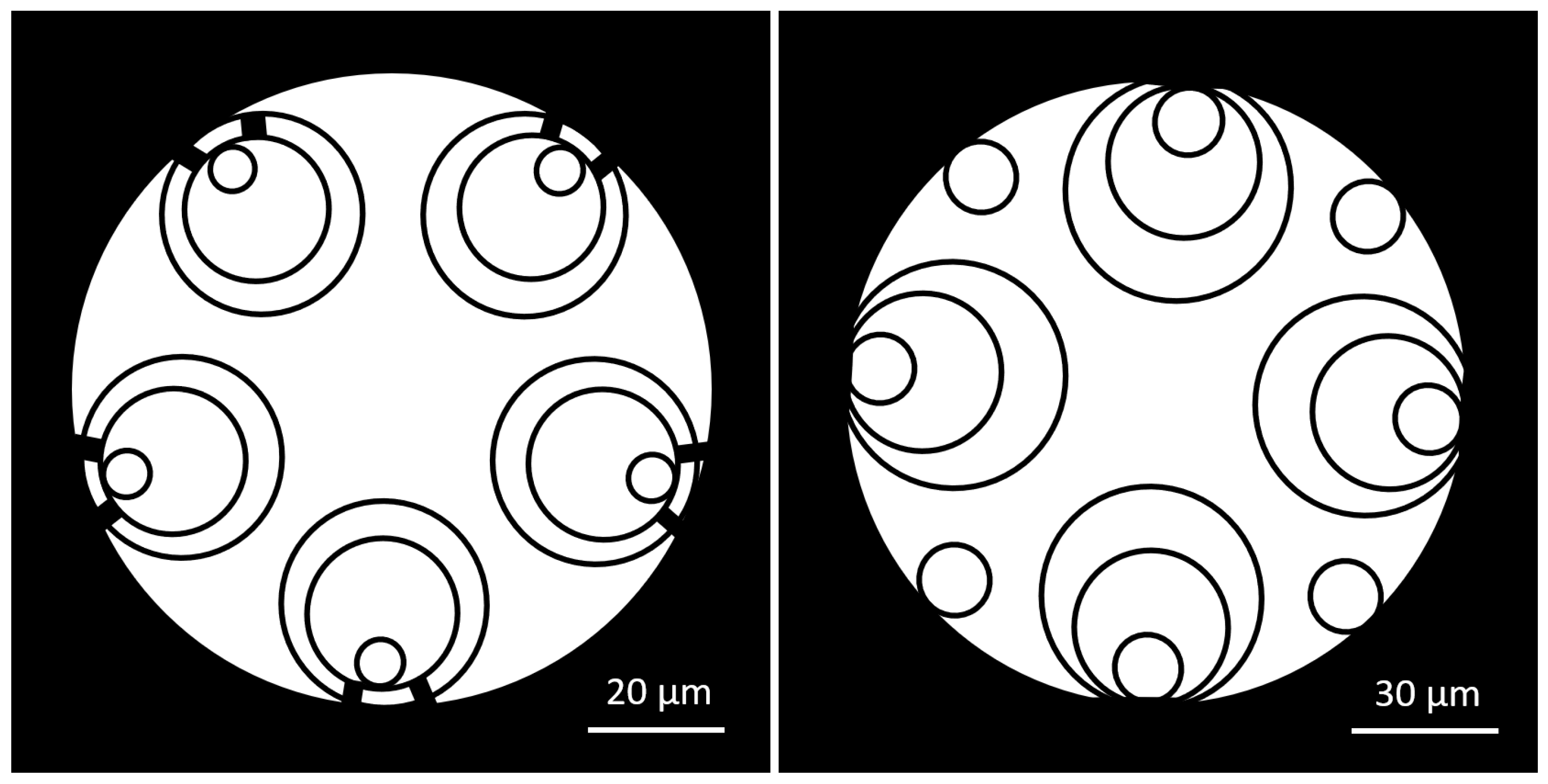
At the ECOC-2025 conference, two groups from China reported making DNANFs with attenuation at 1550 nm close to 0.05 dB/km [26,27]. The technical data of such fibers are presented in Table 3 and their structures in Figure 3.
The structure of the fiber developed at Linfiber [26] incorporates small interstitial tubes located between the nested tubes (Figure 3, right). This modification ensures effective blocking of light escape even with large gaps between nested tubes, measuring up to 13 μm. A gap much larger than in a typical DNANF (3–5 μm) prevents the tubes from contacting each other, despite their local expansion during the drawing process. A larger drawdown ratio without a risk of preform destruction is possible, opening the way to faster production of fibers from larger preforms and improved yield, as once the softened tubes touch, they stick together and cannot be separated. While fiber drawing can be stopped, the damaged part of the preform cut and the drawing process restarted, there is considerable loss of time and produced fiber.
Linfiber researchers made a preform for 100 km of IT-4DNANF with a 240 μm glass diameter, from which 83 km of the low-loss (0.076 dB/km at 1550 nm) fiber was drawn.
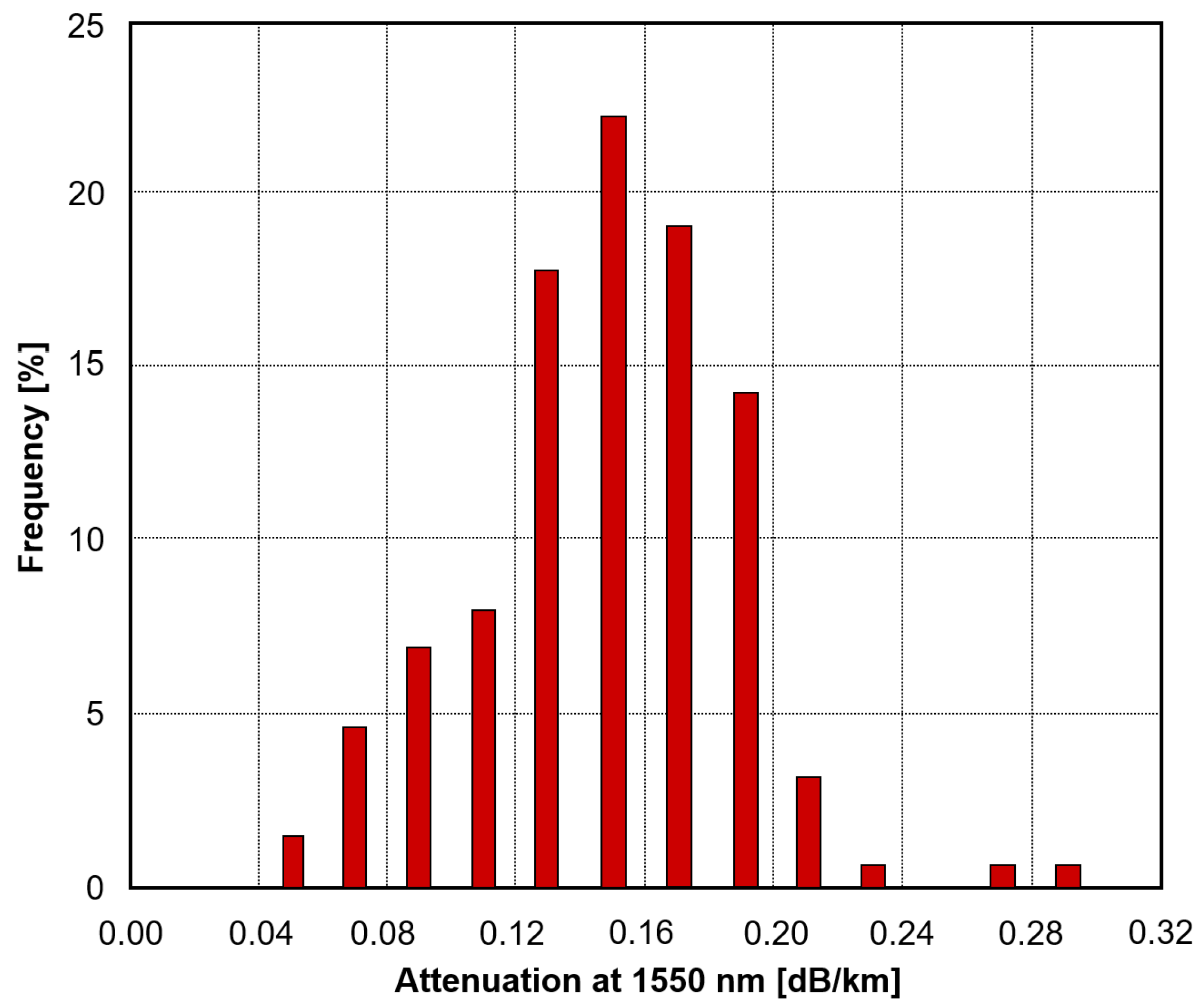
The YOFC fiber [27] had no truncation but included a pair of thick glass supports for each set of five doubly nested tubes, separated by a small gap from the jacket tube. Gaps between the nested tubes were small and measured 4.5 μm. However, one can expect the added supports to reduce the uncontrolled movement of tubes during the drawing process and the risk of them sticking. YOFC published the statistical distribution of attenuation in a 733 km batch of ST-HCF fiber, with an average value of 0.147 dB/km (see Figure 4).
Both fibers transmit in the second window, have thick-walled tubes, and their low-loss bands are narrower compared to DNANFs operating in the first window (see Table 2). Manufacturing yield was given priority over extending transmission bandwidth.

3.4. History of Loss Reduction in NANF/DNANF Fibers

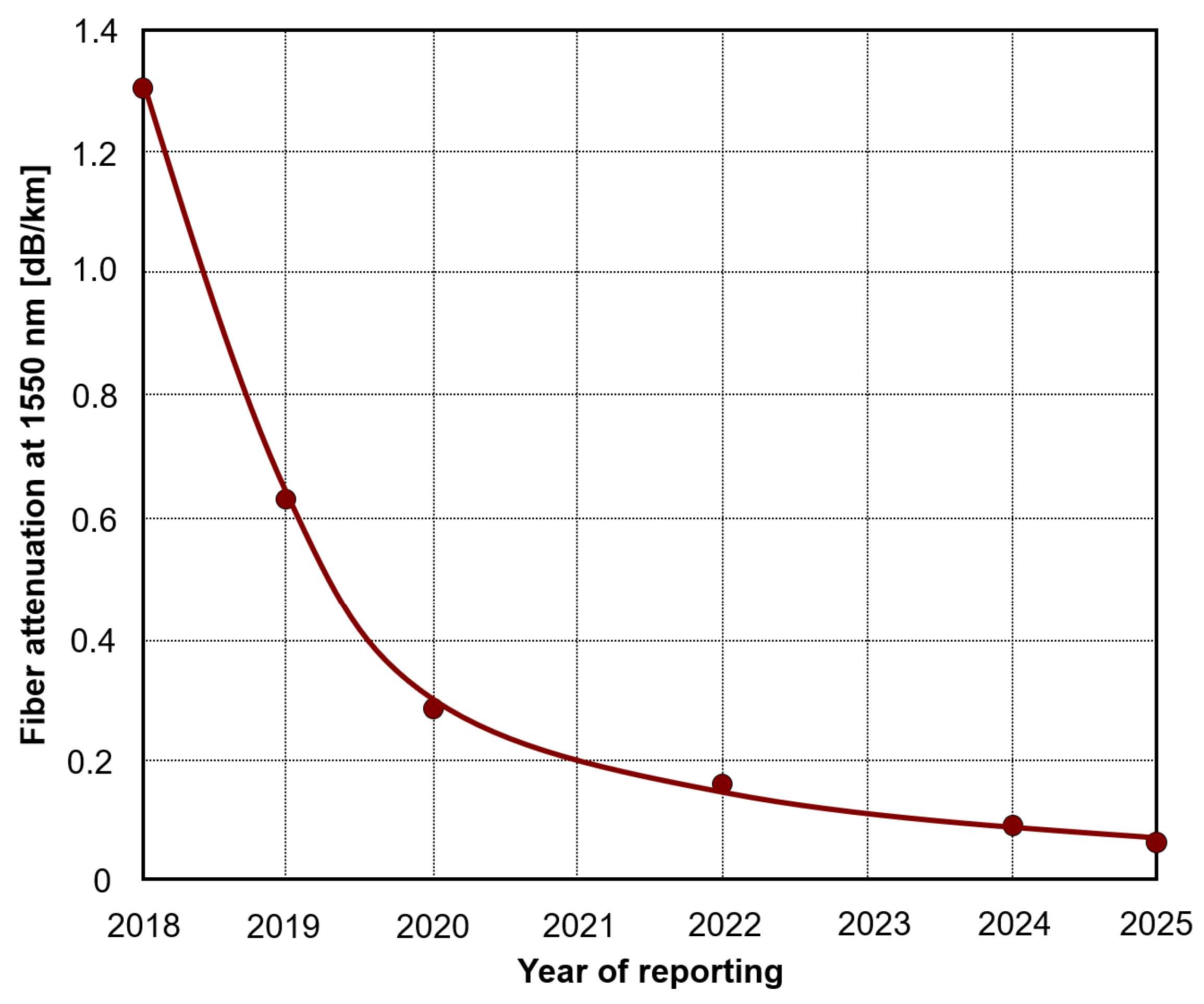
A 15-fold reduction in attenuation in the lowest-loss NANF and later DNANF fibers at 1550 nm wavelength (for which low-loss designs are usually optimized) took place between 2018 and 2024, as shown in Table 4 and Figure 5. Before 2018, the lowest loss in HCF was achieved in an HC-PBGF fiber and equaled 1.7 dB/km.

3.5. Compact TNANF Fibers for Use at 1550 nm

While progress in developing low-loss DNANF variants is impressive (Figure 5) and approaches theoretical predictions for this class of fibers presented in Section 3.7, there remains a problem of the large diameter of cladding, equal to approximately twice the diameter of telecom type SMF or MMF: 200–260 μm vs. 125 μm. This has several undesirable consequences:
  • Decreased fiber density in a cable (by up to 4×);
  • Incompatibility with current fiber connectors (larger hole required), hardware (larger bending diameter of fiber) and tools (e.g., non-standard fiber adapters);
  • Limitations in tight cable bending, e.g., in data centers;
  • Delayed standardization of HCFs until (hopefully) a 125 μm version appears.
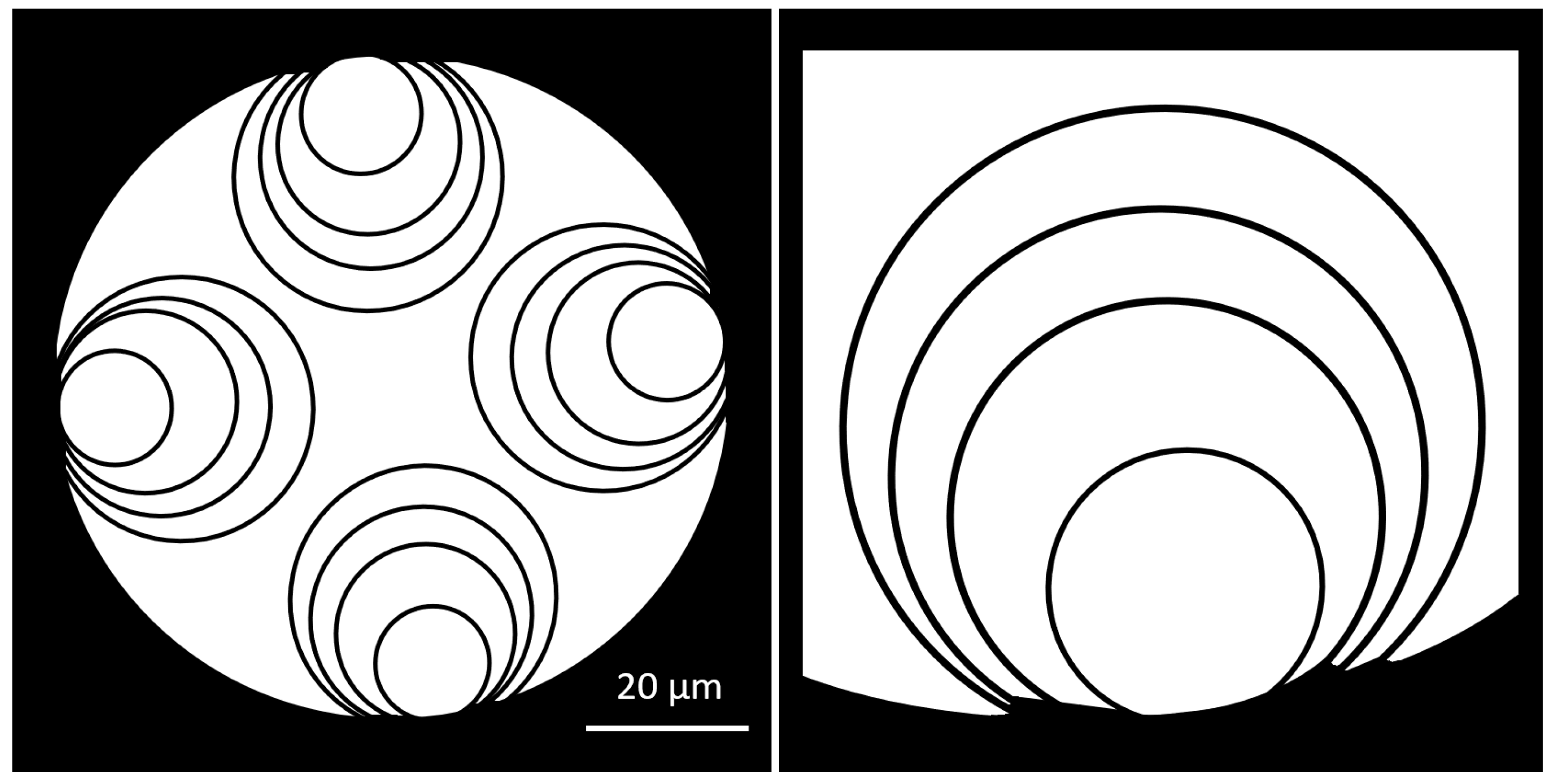
Progress in this respect was made in 2025 at Microsoft Azure Fiber, where a compact 5T-TNANF (5-Tube Triple-Nested Anti-resonant Nodeless Fiber) for the 1550 nm band was developed [31]. The key is the reduction in core diameter to 15 μm, from 28 to 40 μm in other designs (Table 2 and Table 3), and mode field diameter (MFD) to ≈10.5 μm (as in SMF). To avoid a large increase in confinement loss, one more tube was added in each nested set (Figure 6). 5T-TNANF has a larger loss than SMF, and the new DNANFs presented in Section 3.2, Section 3.3 and Section 3.4, but it is low enough for most uses, except for long-distance and undersea networks.
This change allowed them to make two compact fibers (Table 5):
  • SMF-compatible HCF with 125 μm cladding and 250 μm coating diameter;
  • Similar fiber with 20 μm core and 145 μm cladding but lower loss.
Thanks to effective light confinement, TNANF A has an extremely low macro-bending loss at 1550 nm, smaller than required for the “bending-insensitive” ITU-T G.657.B3 fiber. The bending performance of TNANF B is comparable to that of ITU-T G.652.D SMF.

3.6. Ultra-Low-Loss DNANF Fibers for Operation at 850 nm

In 2024, the Microsoft Azure Fiber team designed a single-mode low-loss 5T-DNANF for operation in the 850 nm band [32]. This band is now used for data transmission at short distances (≤1 km) over OM2, OM3, OM4, or OM5 50/125 μm multimode graded index fibers. The new fiber is similar to the one shown in Figure 1 and Figure 2 but with the dimensions of its parts scaled down. The main parameters are presented in Table 6.
This shortwave 5T-DNANF is a quantum leap in transmission performance. Attenuation of 0.30–0.33 dB/km and CD of 2.3 ps/nm × km are typical for solid-core SMFs at 1310 nm, while multimode fibers exhibit a loss of 2.2–2.5 dB/km and chromatic dispersion of approximately −100 ps/nm × km at 850 nm, accompanied by modal dispersion.

3.7. Estimation of Lowest HCF Loss

Theoretical studies on the loss optimization of NANF and DNANF fibers with conventional nested tubes having circular cross-sections (thus ensuring simple preform manufacturing), published until 2023 [33], indicated that practically achievable attenuation, with all components included, amounted to approximately 0.05 dB/km. A 2024 conference paper [23] on record-low-loss DNANF (Section 3.1) also included an estimate of the achievable loss of the current design DNANF with circular nested tubes, with the minimum value equaling 0.04 dB/km at 2000 nm.
The lowest attenuation of DNANF fibers reported by a number of teams in 2024–2025 was in the 0.05–0.11 dB/km range, taking into account a considerable margin of error in loss measurements, unless reasonably uniform fiber lengths of 40 km or more are manufactured [26]. However, the classic DNANF can be greatly improved by eliminating impurities and widening low-loss bandwidth (Section 4.2).
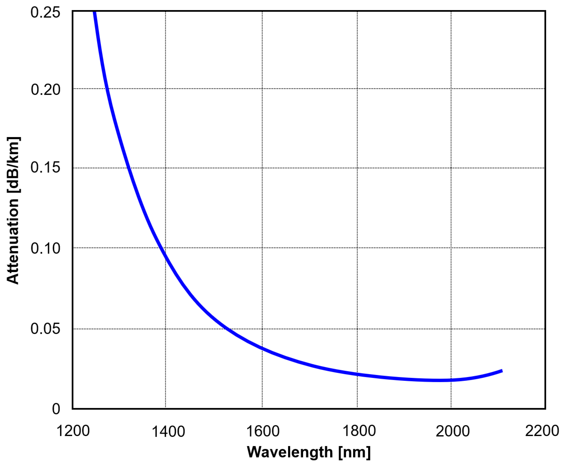
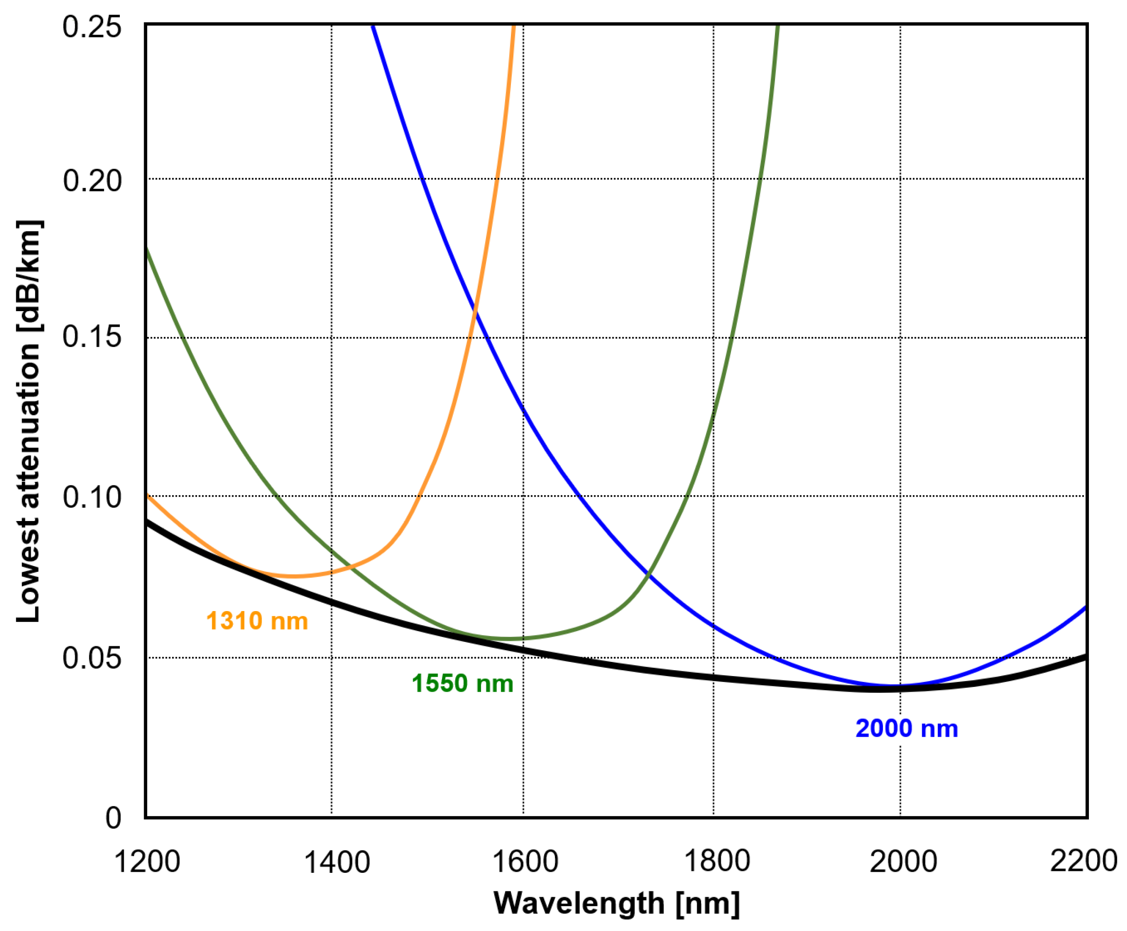
While NANF/DNAF fibers with a low loss at multiple wavelengths from 600 nm to 2000 nm were demonstrated, the lowest loss is achieved only around the wavelength for which the fiber is designed (see Figure 7). The black line shows the loss achievable at each given wavelength in a fiber designed for it. However, any single fiber exhibits increasing loss at wavelengths away from the design value; simplified attenuation curves of fibers optimized for three wavelengths are shown in colors.
This range is widest when the fiber operates in the first transmission window. For 5T-DNANF fibers of this type, the low-loss band limited by a 2-fold increase in the lowest loss is 500–600 nm [22]. The low-loss band can be extended by combining tubes and membranes with different wall thicknesses.
A solution being a subject of several studies (so far simulations only) is to modify the geometry of nested tubes and reduce the confinement loss via the following:
(a)
Insertion of additional membrane(s) within or close to nested tubes to increase reflection in the transmission band. Unfortunately, most such structures are complicated to make and must be made to tight dimensional tolerances to be effective.
(b)
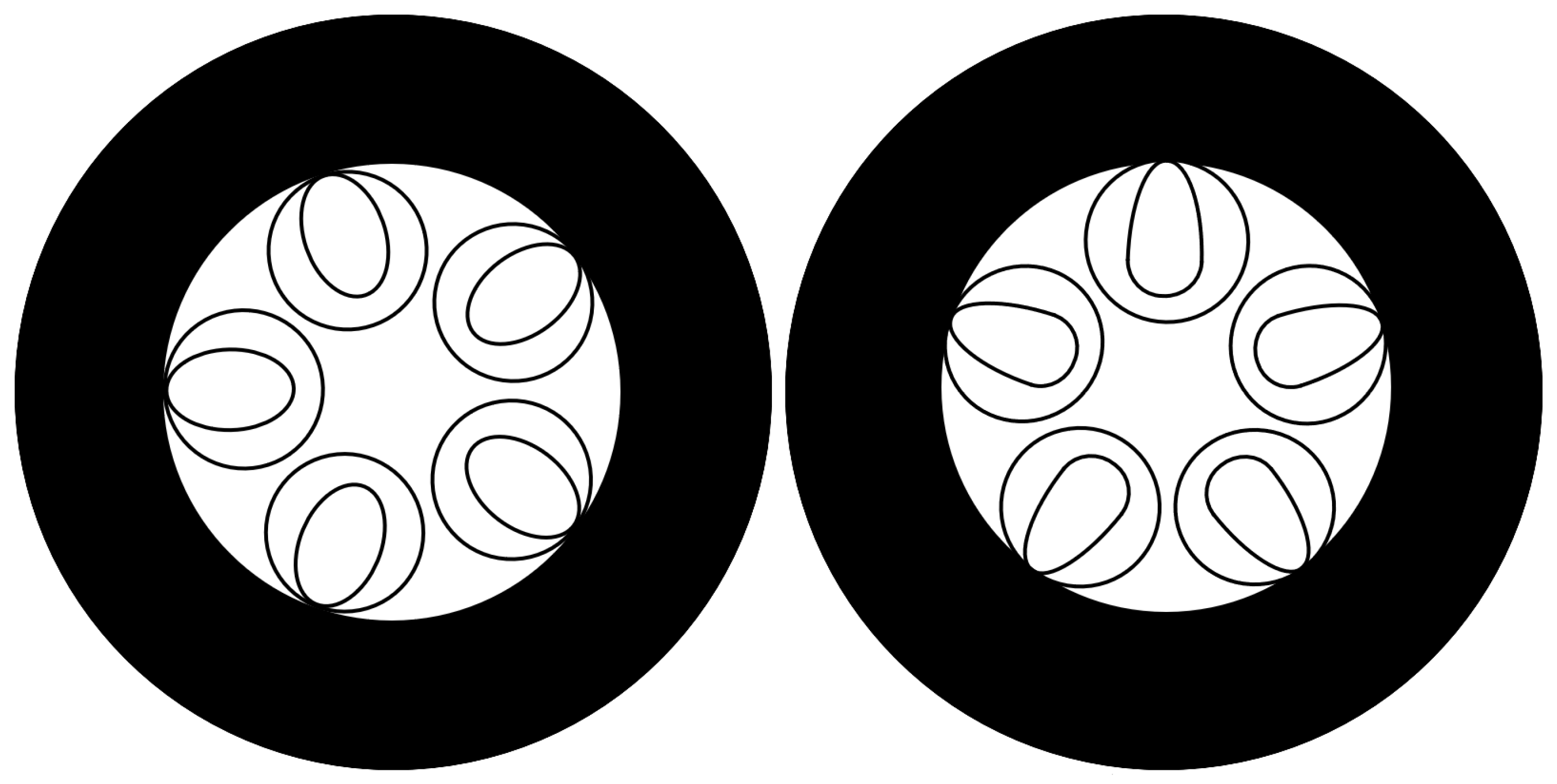
Changing the shape of nested tubes (or only one of them) to elliptical or waterdrop-like for reduced interaction of light with the jacket tube. This design is fairly simple to implement by blowing fused silica tubes of standardized non-circular shape and assembling the preform using the stack-and-draw method.
Design (b) is not new: a study by Shaha et al. [34] indicating a reduction in confinement loss (CL) to ≈0.001 dB/km [1] (p. 15) was published in 2021. A more recent study by Zhang et. al. [35] proposed nested tubes including one of the waterdrop-like shape; the lowest CL over a wide spectral range was obtained with the wider part of the nested tube oriented towards the hollow core in the fiber, there named NWANF1#, having a relatively large core diameter of 40 μm. The opposite orientation of nested tubes reduced the low-loss band (CL ≤ 0.005 dB/km) of 5–DNANF by almost 50%, from 1200–2100 nm (107 THz) to 1200–1650 nm (68 THz). While the wavelength of the lowest attenuation of the first fiber was ≈1970 nm, close to the value predicted in [23] for conventional DNANF, this attenuation was reduced to 0.021 dB/km. This is 40% of the attenuation achieved in the best current HCFs (Section 3.3).
Structures of such loss-optimized DNANFs with non-circular tubes are shown in Figure 8. Exact shapes and dimensions are not fixed, as prototype fibers were not reported. The predicted minimum loss spectrum of the “waterdrop” 5T-DNANF designed for first-order transmission, free of geometry imperfections and absorption by contaminants, is shown in Figure 9. The bandwidth limited by the 1:2 loss variation is approx. 600 nm.

4. Fiber Manufacturing Issues

4.1. General

The stack-and-draw method remains dominant, with pure fused silica as the default material used for all parts of the fiber. In order to increase production rates and decrease fiber loss, manufacturers have to improve their control over the shape of fiber parts and multiple dimensions, in particular diameters of 13–21 tubes and truncation angles.
For comparison, the cladding diameter is the only diameter requiring precise control while drawing all solid-core fibers, in addition to the spin pattern in some single-mode fibers for PMD reduction and stabilization. The latter solution was successfully applied to HC-PBGF fibers in 2021 [36] and to NANF fibers in 2025 [37]. PMD can be also reduced to some extent by twisting cold fiber, causing periodic rotation of ellipticity and other geometry imperfections of the anti-resonant structure. The effectiveness of this method is reduced by the fact that HCF lacks a glass core, which can be subjected to circular strain [38] (pp. 211–212).
An increase in the HCF manufacturing rate requires larger preforms and higher drawing speeds (also when making sub-preforms for final assembly). Progress in this respect will certainly follow patterns from the manufacturing of solid-core fibers, where preforms 4 m long, 4000 km production runs from a single preform, and drawing speeds of up to 20 m/s are the norm. The new structure of the fiber with small interstitial tubes presented by Linfiber [26] (Section 3.3) allowing one to draw 100 km long fibers from larger preforms is a step in this direction, as it allows us to increase gaps between nested tubes and reduces the probability of them sticking together.
Efficient HCF manufacturing with good yield requires multi-dimensional monitoring and closed-loop adjustment of tube dimensions, effected primarily by varying the pressure of gas fed independently to sets of all tubes of each size via a glass manifold attached to the preform, furnace temperature and drawing tension. Systems of this kind are usually a closely guarded company secret. The most detailed descriptions of drawing process known to the author were published in 2019 [39].

4.2. Absorption by Contaminants in the Fiber

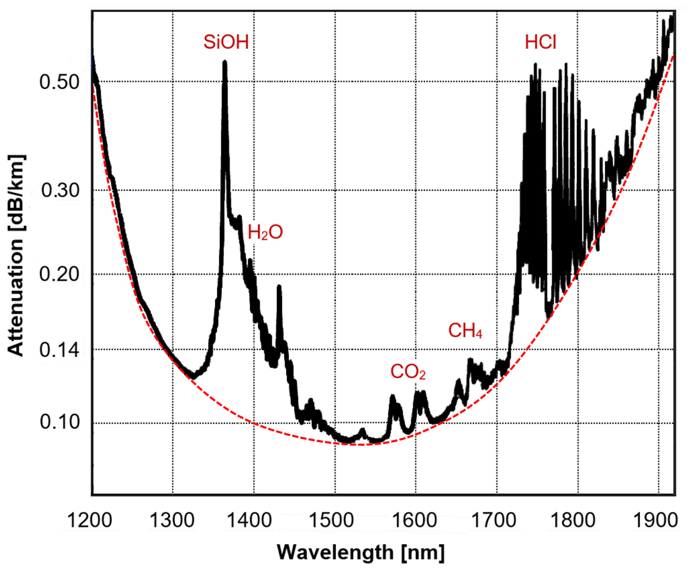
There is a serious problem, affecting primarily HCFs intended for coherent DWDM transmission systems: multiple gas and vapor absorption bands, with the strongest of them corresponding to water vapor. Water deposited on the surfaces of fused silica reacts therewith, producing silanol (SiOH), a compound absorbing light at 1364 nm. Non-polar constituents of air, i.e., nitrogen, oxygen and argon, do not attach to fused silica surfaces. Other compounds present in preform production plants typically include the following:
  • Light hydrocarbons: methane (CH4), ethane (C2H6), propane (C3H8), and butane (C4H10) used as fuels for gas burners in glass processing;
  • Fluorine, chlorine and hydrogen chloride (HCl) outgassing from hot fused silica tubes, where Cl2 and F2 are used to remove traces of hydroxyl ions from fused silica;
  • Carbon dioxide (CO2).
More data on this subject can be found in the previous review [1] (pp. 18–20). Carbon dioxide exhibits a fine spectral structure of absorption made of a large number of equally spaced, narrow absorption lines. There are several other substances exhibiting this property, e.g., acetylene (C2H2) and hydrogen cyanide (HCN) used in wavelength reference cells.
Narrow, periodic absorption bands of CO2 can be detected by measuring fiber loss with an optical spectrum analyzer set to a resolution of 0.05 nm or better, or a tunable laser with a wavelength step of the same size. Such measurement reveals a sub nm fine spectral loss structure; peak added attenuation can exceed the attenuation of a “clean” fiber [24].
To suppress the loss added by impurities, it will be necessary to establish an atmosphere that is free of the above-mentioned contaminants in the HCF manufacturing plant, or introduce purging of preforms with dry, highly pure filler gas like argon and prevent entry of air afterwards, with the ends of the finished fiber sealed by fusion.

5. Role and Standardization of Hollow-Core Fibers

5.1. SMF, MCF, and HCF Market Segments

Looking at expected applications, three main categories of telecom fibers, namely SMF, MCF and HCF, appear complementary, with their distinct applications listed below:
  • SMF: low-cost, established technology for most networks, especially when applications are cost-sensitive, e.g., in fiber access networks (FTTH).
  • MCF: fibers compatible with SMFs for high-density applications and parallel transmission; splicing MCF to a bunch of SMFs requires an expensive “fanout”.
  • HCF: fibers with unique properties for applications with special requirements (low latency, low loss, low non-linearity, wide bandwidth, high power transmission) but incompatible with other fibers.

5.2. Standardization and Fusion Splicing of Fibers

HCFs are fundamentally different from solid-core fibers, MCF included, and cannot be simply substituted for them without first creating and standardizing an “ecosystem” of passive components, splicing and coupling techniques (including HCF–SMF splicing), dedicated test instruments, in particular OTDRs, and light sources operating at new wavelengths. Later, transceivers and optical amplifiers for the new bands, e.g., 1650–2050 nm, and power levels will be required. While current HCFs are optimized for the C band (1530–1565 nm) in order to be compatible with widely used SMFs and associated active equipment, this may change later on, as the longwave band (1600–2100 nm) promises the lowest attenuation in fused silica HCF (Figure 6).
Commercial deployment started in 2024 for both HCF [3,40,41] and MCF [42]. Standardization work on MCFs began at ITU-T in 2024 [43], with important applications expected in submarine cables, where compactness of the optical core is critical.
Standardization of HCFs is absent, as fiber designs continue to evolve (Section 3). The dimensions of the core, MSD, and cladding diameters are of critical importance here, as they need to be identical (within one category of HCF) to allow splicing of fibers from different vendors.
A structural mismatch caused by a different number of tubes, currently four, five, or six (Section 3), produces a loss of approx. 0.045 dB [44], equal to the loss of the best DNANF fibers achieved over a distance of 1 km (Section 3.3). Still, the loss of a fusion splice between two identical DNANFs can be below 0.2 dB under real installation conditions [41]. The loss of an SMF-HCF splice also contains a fixed components loss of ≈0.08 dB produced by structural mismatch [45] and is higher. It equals 0.2–1 dB [1], primarily due to the following:
  • Different mode field diameters of SMF (9–13 μm) and HCF (18–32 μm);
  • Collapse of fine anti-resonant tubes having membranes which are only 0.4–1.2 μm thick.
Splicing of HCFs is presented in more detail in the review [1].
Considering the recently developed “compact” Microsoft Azure fiber (Section 3.5), there is a good chance that a satisfactory medium-loss HCF for 1550 nm and 850 nm bands with 125 μm cladding and 200 or 250 μm protective coating (as in SMFs and MMFs) will be developed and manufactured. However, the same is rather unlikely for ultra-low-loss HCFs intended for long-distance networks (Section 3.1 and Section 3.3).

5.3. Demise of HC-PBGF Fibers

While this older type of hollow-core fiber, known as Hollow-Core Photonic Bandgap Fiber (HC-PBGF) [1] (pp. 5–10), was still manufactured and developed in 2022, primarily at Furukawa/OFS [36,46], and commercially deployed on a modest scale, after 2023, there are no reports on further research conducted at Furukawa [47] or elsewhere. The reasons for HC-PBGFs losing market to DNANFs include the following:
  • Complicated, labor intensive, and expensive preform manufacturing involving 250–300 glass tubes instead of less than 20 in a 4-DNANF or 5-DNANF;
  • High attenuation, typically 2.5–5 dB/km in (some parts of the) 1550 nm band;
  • Narrow low-loss band, usually made of several sub-bands 10–30 nm wide [47];
  • High polarization mode dispersion (PMD) despite spinning at 100 rev/m rate [36].

6. Optical Amplifiers for Use with HCFs

6.1. New Fibers—New Wavelength Bands

Current DNANFs for telecom network applications are designed for minimum loss at 1550 nm (Section 3.1 and Section 3.3) and can operate with Erbium-Doped Fiber Amplifiers (EDFAs) covering the 1530–1565 nm and 1570–1610 nm wavelength bands, depending on the host glass used. EDFAs provide amplification in the C band and most of the L band (Table 7), offering a combined bandwidth of ≈9.0 THz. Amplification in both bands requires two amplifiers and WDM couplers. EDFAs are widely used with solid-core single-mode fibers having the lowest loss (0.16–0.21 dB/km) at 1550–1570 nm.
The conventional single-mode fiber conforming to ITU-T Recommendation G.652.D [7] exhibits relatively low attenuation, ≤0.35 dB/km, across a much wider band, approximately 1260–1675 nm, which corresponds to the 179–238 THz frequency range and 59 THz bandwidth. DNANF fibers of suitable design can exhibit low attenuation in an even wider band. The newest example is a proposed (simulated) fiber design with elliptical outer tubes in nested sets and small interstitial tubes blocking leakage of light, with expected confinement loss ≤ 0.017 dB/km over a 1200–2200 nm transmission band (136–250 THz, 114 THz wide) [49]. Two other fiber designs with tubes elongated in the radial direction are presented in Section 3.7.
Fibers with such properties cannot be made yet due to the absorption caused by several contaminants trapped in the fiber (Figure 10) and the need for optimized photonic cladding manufactured to tight dimensional tolerances. Both problems appear solvable, however. Making full use of wideband HCF in ultra-high-capacity transport networks will need amplifiers covering at least a majority of the bandwidth indicated above.
The low-loss band of perfected DNANF, including new designs with elongated tubes, extends towards long wavelengths, with their minimum predicted roughly in the 1700–2050 nm (146–176 THz) range (Figure 7) and offering 30 THz of optical bandwidth, in comparison to ≈9 THz (186–196 THz with a gap) available in EDFAs of both types. The optical band extending beyond 1675 nm has not been standardized yet (Table 7).
Raman amplification in HCF is impossible because optical non-linearity in air-filled DNANF is typically 5 × 10⁴ … 5 × 10⁵ lower than in solid-core fused silica SMFs, due to the following:
  • Very low overlap of guided radiation with glass (2 × 10⁻⁵ … 1 × 10⁻⁴);
  • Larger (by a factor of 5–10×) effective mode area (Aeff) compared to SMF [1,7,8,9] and correspondingly smaller power density.
Negligible non-linearity is a big advantage in several applications, including DWDM networks and remote powering over fiber; therefore, inserting sections of solid-core fibers as an amplification medium is not acceptable. While semiconductor optical amplifiers (SOAs) can be made to operate at essentially any wavelength by adjusting the semiconductor’s bandgap, SOAs have limited output power and a relatively high noise figure.
The best options left for optical amplification in the bands not covered by EDFAs are fiber amplifiers with three dopants other than erbium:
  • Bismuth (BDFA, ≈1300–1500 nm);
  • Thulium (TDFA, ≈1900–2020 nm);
  • Holmium (HDFA, ≈2000–2130 nm).

6.2. Bismuth-Doped Fiber Amplifiers for Short Wavelengths

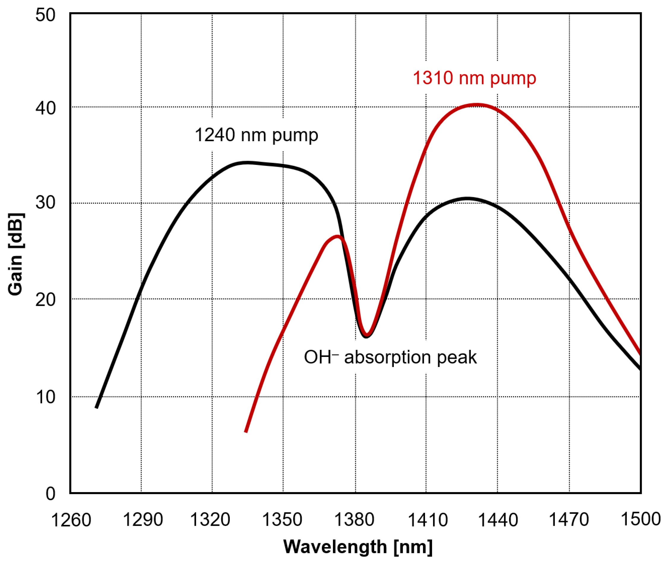
Amplification at short wavelengths, approximately in the 1300–1500 nm band or a large part of it, with a Bismuth-Doped Fiber Amplifier (BDFA) has been reported by several researchers during recent years [50,51]. This is a dual amplifier using a single length of germanosilicate (SiO2 + GeO2) glass fiber doped with bismuth oxide and phosphorus pentoxide (P2O5). The amplification of radiation originates from bismuth-related active centers (BACs) associated with phosphorus (BACs-P) and silicon (BACs-Si); phosphorus and silicon content in the fiber’s core equals approx. 0.9% and 45%, respectively. BACs-P provide amplification at short wavelengths, ≈1300–1400 nm, and a part of this amplified radiation is absorbed as pump by BACs-Si providing gain at longer wavelengths. Single BDFA pumped at short wavelength(s), e.g., ≈1240 nm and optionally ≈1275 nm, with a carefully adjusted P:Si ratio close to 1.8% [50], offers high gain, up to 30–45 dB, a wide gain spectrum (100–200 nm) and a low noise figure of 5–9 dB. With an increase in pump wavelength, BAC-Si active centers are gradually pumped directly and provide higher gain, as one may notice in Figure 11.
Yet, BDFA still does not work in the entire O + E + S range (Table 7), being limited to the E band as well as parts of adjacent O and S bands. The spectral range of gain can be extended towards longer wavelengths to also include the C band by cascading BDFA and EDFA or co-doping the active fiber with bismuth and erbium, at the expense of increased gain variability with wavelength and input power [52]. If the active fiber is co-doped with bismuth and germanium, active centers of the BAC-Ge type can provide optical gain at longer wavelengths equaling ≈1680–1750 nm [53].
Current BDFAs suffer from two issues:
  • Active fiber has a limited Bi content (≈100 ppm) and must be long: 90–500 m;
  • OH ions in active fibers produce non-negligible absorption at ≈1383 nm, splitting gain spectrum into two parts. Careful drying of the preform with hot chlorine before consolidation will be required to eliminate it.
An example of the gain spectrum with a pronounced “water peak” is shown in Figure 11. The situation becomes worse when DNANF is contaminated by silanol and water vapor, producing another loss band at 1364 nm, accompanied by a “tail” extending to 1440 nm (Figure 10).

6.3. Thulium-Doped Fiber Amplifiers for Long Wavelengths

For amplification at long wavelengths, a suitable Thulium-Doped Fiber Amplifier (TDFA) was demonstrated at the University of Southampton back in 2013 [54], with a wide bandwidth of ≈1900–2020 nm (divided into short- and long-wavelength gain sections), peak gain of ≈40 dB, low noise figure amounting to approx. 6 dB (similarly to EDFA), and high slope efficiency of ≈50% at 1565 nm pump wavelength, compared to ≈40% in a typical short-wave EDFA pumped at 980 nm. Later research conducted at the University of Southampton [55] proved it is possible to operate a set of four or more optimized TDFAs covering the 1660–2050 nm spectrum, albeit with significant spectral variability in gain. A theoretical study of advanced TDFA with a flat gain profile in a more than 300 nm wide (1690–1986 nm) spectrum was published in 2025 [56], but a similar device is yet to be assembled in the lab and used in transmission experiments.
Amplification in the adjacent 2000–2130 nm band, the longwave end of the low-loss spectrum of DNANF (Figure 4), may be possible with a Holmium-Doped Fiber Amplifier (HDFA) pumped with a 1950 nm or 2000 nm laser [57,58].
Amplifiers listed above, once fully developed, may together provide amplification over the majority of the low-loss spectrum of 5-DNANF, ca. 1320–2130 nm (141–227 THz, 76 THz), but will be complicated, with maybe six or eight sub-amplifiers covering parts of the transmission spectrum (including a number of new long-wave windows), numerous pump lasers and WDM couplers, plus a controller. Their high cost will be justified only in the most advanced DWDM networks. Other expected disadvantages of such multi-band amplifiers include relatively high power consumption and failure rates.

7. Deployment of HCFs in Microsoft Azure Data Centers and Links

In November 2024, Microsoft announced a large project, spanning a period of 2 years, involving multiple data centers for Microsoft Azure AI services [3,41]. One of the novelties included a large-scale (15,000 km of hollow core fibers) deployment of cables with a mix of HCF and SMF fibers between data centers, e.g., 32 HCF + 48 SMF [41]. For this solution to be cost-effective, separation of latency-sensitive and latency-insensitive traffic is needed.
HCFs are also installed inside data centers to reduce latency and increase processing power, replacing SMF, MMF and twisted-pair cables (Section 2). In this application, HCF properties of interest primarily include the following:
  • Low latency;
  • Bending tolerance,
  • Small core diameter and MFD for splicing to SMFs.
The latter explains the interest Microsoft has shown in developing compact HCFs (Section 3.5).
Due to the short lengths of fiber links used in large data centers (≤500 m, mainly ≤200 m), fiber attenuation similar to that of multimode fibers operating at 850 nm (≤2.5 dB/km) is acceptable. With considerable deviation in attenuation values of currently manufactured HCFs [27] one can imagine selection of HCFs at the production plant into at least two separate “outside plant/low loss” and “indoor plant/high loss” grades; such practice existed shortly at the beginning of manufacturing of SMFs and MMFs in the mid-1980s.
Microsoft Azure Fiber did not publish an official specification of its 5T-DNANF fiber. While some websites indicate that average attenuation close to 0.10 dB/km is achieved, this value likely came from research papers presenting lowest-loss fiber samples from their plant [22,23]. A blog by Forster et al. [41] revealed that the average loss of HCF-HCF fusion splice in one 2025 network project was 0.16 dB. For 2 km of a cable section with a 0.10 dB/km fiber, which is an ambitious target considering YOFC production data [27] shown in Figure 4, the loss of the installed cable line is no less than 0.18 dB/km. It was also revealed by a key researcher at Microsoft Azure Fiber, F. Poletti, that the “pilot” phase of the project included installation of 1200 km of HCF with satisfactory results [59]. The decision to build a large network linking Microsoft Azure data centers supporting premium AI services indicates a high level of trust in fiber manufacturing capabilities. Despite having its own manufacturing plant in Romsey, UK, Microsoft made agreements with Corning Inc., the world’s largest manufacturer of optical fibers, and Heraeus Covantics, a German manufacturer of specially fused silica glass (and recently of optical fibers, too) for manufacturing of HCF preforms and finished fibers by those companies at two sites in the U.S. [60].
Another large corporation recently installing HCF cables to reduce latency in links between data centers is Amazon Web Services [61].

8. HCF-Related Future Technologies

Optical fibers themselves do not constitute a telecom or datacom network or even a simple point-to-point data link. Below is a list of components and instruments necessary in a high-end HCF “ecosystem” in the medium-term future. Some of them may already exist but are not yet offered commercially for this purpose. The list is not exhaustive:
  • Passive components for HCFs: DWDM multiplexers, filters, splitters, optical switches and circulators for the 1700–2100 nm band.
  • Low-noise photodiodes and DFB lasers for transmitters and receivers operating at wavelengths of up to 2100 nm. “Extended InGaAs” photodiodes with indium content exceeding the standard 53% ratio and lasers on InP substrate covering this band are manufactured on a small scale and are expensive. Because of reduced bandgap, extended InGaAs photodiodes exhibit larger dark current and may need thermoelectric coolers to reduce noise.
  • Complete optical transponders for the 1700–2100 nm band.
  • OTDRs, power meters, and portable light sources for the 1700–2100 nm band.
  • Portable TV cameras, offering sensitivity of up to 2100 nm, for inspection of radiation leakage in facilities with high power transmission/amplification.
The situation has not apparently changed since the last review [1], despite commercial deployments of HCFs, because of the following factors:
  • These networks are operating at established wavelengths, e.g., 1550 nm or (maybe) 850 nm, for compatibility with existing SMF or MMF “ecosystems”, respectively;
  • Microsoft, the dominant HCF user for now (Section 7), is able to custom order components and test equipment without this information making news in professional media.

9. Discussion

The most dynamic advancements occurred in the development of low-loss, compact, and easier-to-make hollow-core fibers. There are three major competing manufacturers, Microsoft, YOFC and Linfiber, with Corning and Heraeus Covantics engaged in fiber production for Microsoft but not reporting their own fiber designs. While this competition ensures rapid advances in technology, the multiplying fiber designs are incompatible. Standardization, most likely with several HCF categories formulated for different applications, as in ITU-T G.652, G.654 or G.657 recommendations [7,8,9], is essential for the mass adoption of hollow-core fibers in telecom networks. One reason is that incompatible anti-resonant structures (number of tubes, interstitial tubes, supports) and cladding diameters are a serious problem when fusion splicing different HCFs (Section 5.2).
The next subject for future work is the elimination of absorption by contaminants trapped inside the fiber, as currently a majority of (theoretically) available fiber bandwidth is (actually) blocked by multiple loss peaks produced primarily by water vapor, silanol, and carbon dioxide (Section 4.2). Looking at the research papers, the elimination of contaminants currently attracts little attention, because of the following:
  • Loss in the 1550 nm band (the main benchmark) is not affected;
  • Improvements to anti-resonance structures and drawing are more important.
Large-scale manufacturing of HCFs at relatively low cost is within reach if the solutions reported by Linfiber [26] for drawing long lengths of HCFs are implemented and further developed, but consistency and yield of low-loss fibers continue to remain an important issue. YOFC data [27] (Figure 4) show that while some 5% of manufactured ST-HCF had a loss value close to 0.05 dB/km advertised at conferences, the actual average value of 0.147 dB/km was 3× larger, and the worst 5% exceeded 0.22 dB/km, a value familiar from cheap SMFs. The manufacturer did not reveal the reasons behind that, but the most likely ones include the following:
  • Variable diameter of core and nested tubes along the fiber, with locally increased confinement loss;
  • Various light-absorbing and -scattering contaminants (dust, glass particles), both contained in the air (Figure 10) and deposited on glass surfaces inside the fiber.
The range of potential solutions includes improved control of diameters during drawing, cleanroom conditions and filling of preforms with dry, clean gas, such as argon. Still, even the most lossy fibers are fine for short (≤500 m) connections inside data centers and medium-length links between them.
Progress was made in developing amplifiers covering most of the HCF low-loss spectrum (≈1300–2100 nm); several variants of BDFA and TDFA amplifiers with parameters comparable to those of EDFA were demonstrated in laboratories (Section 6). The commercial introduction of wavelength-multiplexed banks of these amplifiers may occur soon, but complicated setups of multiple amplifiers will be expensive and require special controllers to keep the gain spectrum flat.
So far, there is no development of passive components, transceivers and test equipment for an extended range of wavelengths available in HCFs (Section 8). This is explained by focus on the development of HCFs themselves and their use in data centers.

10. Materials and Methods

This paper is of review type, based on data already published, mostly in the 2022–2025 period; data gathering stopped on 31 March 2026. Data collected during work on this paper include the following:
  • Scientific and technical publications, standards and product data sheets;
  • Copies of press releases and company publications, usually with photos and other graphics saved as separate files;
  • Drawings and photographs extracted from publications in PDF format or saved from websites for further analysis, particularly of fiber geometry. Note: Figures included in this paper were created anew to look like ones in References but are not their direct copies.
Generative artificial intelligence (GenAI) was not used.

Funding

This research and APC were funded by the Polish Ministry of Science and Higher Education by financing statutory activities of National Institute of Telecommunications (no specific contract number). Work at the Institute was done within Project No. 12.30.002.6 “Design of photonic structures, including diffractive optical components for fiber optic communications and measurements”, distributing part of this funding to the department where the author is employed.

Institutional Review Board Statement

Not applicable.

Informed Consent Statement

Not applicable.

Data Availability Statement

The author will maintain a full set of data gathered for the purpose of writing this paper indefinitely. Availability to third parties, however, is restricted by the fact that large proportion of these materials is not of “open access” type. All other data are available to anyone within reasonable request.

Conflicts of Interest

The author declares no conflicts of interest. The funders had no role in the design of the study; in the collection, analyses, or interpretation of data; in the writing of the manuscript; or in the decision to publish the results.

Abbreviations

The following abbreviations are used in this paper:
4-DNANFDouble Nested Anti-Resonant Nodeless Fiber with 4 non-truncated tube sets
5-DNANFDouble Nested Anti-Resonant Nodeless Fiber with 5 non-truncated tube sets
4T-DNANFDouble Nested Anti-Resonant Nodeless Fiber with 4 truncated tube sets
5T-DNANFDouble Nested Anti-Resonant Nodeless Fiber with 5 truncated tube sets
AIArtificial Intelligence
ARF Anti-Resonant Fiber
ARROWAnti-Resonant Reflecting Optical Waveguide
BDFABismuth-Doped Fiber Amplifier
C band1530–1565 nm optical band (Conventional Band)
CAPEX Capital Expenses
CD Chromatic Dispersion
CL Confinement Loss
DNANF Double-Nested Anti-Resonant Nodeless Fiber
DWDM Dense Wavelength Division Multiplexing
E band1360–1460 nm optical band (Extended Wavelength Band)
EDFA Erbium-Doped Fiber Amplifier
FOGFiber Optic Gyroscope
FTTHFiber to the Home (fully fiber optic broadband access network)
HST High-Speed Trading
HCF Hollow-Core Fiber
HC-PBGFHollow-Core Photonic Bandgap Fiber
HDFAHolmium-Doped Fiber Amplifier
HOMHigher-Order Mode
HOMERHigher-Order Mode Extinction Ratio
IT-DNANFInterstitial-Tube-assisted Double-Nested Anti-Resonant Nodeless Fiber
ITU-TInternational Telecommunication Union–Technical Standardization Sector
MCFMulti-Core Fiber
L band1565–1625 nm optical band (Longwave Band)
MFDMode Field Diameter
MMFMultimode Fiber (with solid core)
NANumerical Aperture
MSDMicrostructure Diameter (diameter of HCF without solid jacket tube)
NANFNested Anti-Resonant Nodeless Fiber
O band1260–1360 nm optical band (Old Band—the first one used with SMF)
OPEXOperating Expenses
OTDROptical Time Domain Reflectometer
OTNOptical Transport Network
PBGFPhotonic Bandgap Fiber
PMDPolarization Mode Dispersion
PSCFPure Silica Core Fiber
S Band1460–1530 nm optical band (Shortwave Band)
SMFSingle-Mode Fiber (with solid core and cladding)
SPMSelf-Phase Mixing
SSLSurface Scattering Loss
TDFAThulium-Doped Fiber Amplifier
U band1625–1675 nm optical band (Ultralong Wavelength Band)

References

  1. Borzycki, K.; Osuch, T. Hollow-Core Optical Fibers for Telecommunications and Data Transmission. Appl. Sci. 2023, 13, 10699. [Google Scholar] [CrossRef]
  2. ITU-T Recommendation G.652: Characteristics of a Single-Mode Optical Fibre Cable. CCITT (The International Telegraph and Telephone Consultative Committee), Geneva, Switzerland, October 1984. (Published in Printed Version Only). Available online: https://www.itu.int/itu-t/recommendations/rec.aspx?rec=4091&lang=en (accessed on 25 November 2025).
  3. Zhang, E. Why Is Hollow-Core Fiber So Popular? LinkedIn. 13 January 2025. Available online: https://www.linkedin.com/pulse/why-hollow-core-fiber-so-popular-evelyn-zhang-cwx4c (accessed on 2 December 2025).
  4. Wang, C. 2025/2026 China Mobile Optical Cable Tender Awards Released. CRU Group. 11 June 2025. Available online: https://www.crugroup.com/en/communities/thought-leadership/2025/2025-2026-China-Mobile-optical-cable-tender-awards-released/ (accessed on 12 December 2025).
  5. Saitoh, K.; Matsuo, S. Multicore Fiber Technology. J. Light. Technol. 2015, 1, 55–66. [Google Scholar] [CrossRef]
  6. Pryamikov, A.D.; Biriukov, A.S.; Kosolapov, A.F.; Plotnichenko, V.G.; Semjonov, S.L.; Dianov, E.M. Demonstration of a waveguide regime for a silica hollow-core microstructured optical fiber with a negative curvature of the core boundary in the spectral region > 3.5 μm. Opt. Express 2011, 19, 1441–1448. [Google Scholar] [CrossRef]
  7. ITU-T Recommendation G.652; Characteristics of a Single-Mode Optical Fibre and Cable. International Telecommunication Union: Geneva, Switzerland, 2024. Available online: https://www.itu.int/myworkspace/t-rec/item?id=16060&lang=en (accessed on 22 April 2026).
  8. ITU-T Recommendation G.654; Characteristics of a Cut-Off Shifted Single-Mode Optical Fibre and Cable. International Telecommunication Union: Geneva, Switzerland, 2024. Available online: https://www.itu.int/myworkspace/t-rec/item?id=16061&lang=en (accessed on 22 April 2026).
  9. ITU-T Recommendation G.657; Characteristics of a Bending-Loss Insensitive Single-Mode Optical Fibre and Cable. International Telecommunication Union: Geneva, Switzerland, 2024. Available online: https://www.itu.int/myworkspace/t-rec/item?id=16037&lang=en (accessed on 22 April 2026).
  10. TIA-492AAAE; Detail Specification for 50-um Core Diameter/125-um Cladding Diameter Class 1a Graded-Index Multimode Optical Fibers with Laser-Optimized Bandwidth Characteristics Specified for Wavelength Division Multiplexing. Telecommunications Industry Association: Arlington, Virginia, USA, 2016. Available online: https://store.accuristech.com/standards/tia-tia-492aaae?product_id=2592718 (accessed on 22 April 2026).
  11. IEC 60793-2-10; Optical Fibres—Part 2-10: Product Specifications-Sectional Specification for Category A1 Multimode Fibres. International Electrotechnical Commission: Geneva, Switzerland, 2019. Available online: https://webstore.iec.ch/en/publication/62020 (accessed on 22 April 2026).
  12. Ciddor, P.E. Refractive Index of Air: New Equations for the Visible and Near Infrared. Appl. Opt. 1996, 35, 1566–1573. [Google Scholar] [CrossRef]
  13. Jasion, G.T.; Sakr, H.; Hayes, J.R.; Sandoghchi, S.R.; Hooper, L.; Fokoua, E.N.; Saljoghei, A.; Mulvad, H.C.; Alonso, M.; Taranta, A. 0.174 dB/km Hollow Core Double Nested Antiresonant Nodeless Fiber (DNANF). In Proceedings of the 2022 Optical Fiber Communications Conference and Exhibition (OFC), San Diego, CA, USA, 6–10 March 2022. Paper Th4C.7. [Google Scholar] [CrossRef]
  14. FarBand Ultra Low Loss and Large Effective Area Single-mode Fibre. Yangtze Optical Fibre and Cable. 2019. Available online: https://yofc-oss.oss-cn-beijing.aliyuncs.com/en/upload/20190702/1deoels8o13po8kkr.pdf (accessed on 29 January 2026).
  15. Corning TXF Optical Fiber Product Information PI1433. Corning Inc.. November 2022. Available online: https://www.corning.com/media/worldwide/coc/documents/Fiber/product-information-sheets/PI-1433-AEN.pdf (accessed on 24 January 2026).
  16. Corning Vascade EX2000 Optical Fiber Product Information PI-1440. Corning Inc.. March 2023. Available online: https://www.corning.com/media/worldwide/coc/documents/Fiber/product-information-sheets/PI-1440.pdf (accessed on 29 January 2026).
  17. Corning® SMF-28® ULL S+ Optical Fiber Product Information PI-1471. Corning Inc.. March 2023. Available online: https://www.corning.com/media/worldwide/coc/documents/Fiber/product-information-sheets/PI-1471.pdf (accessed on 29 January 2026).
  18. Z-PLUS Fiber 150 Advanced Pure Silica Core Single Mode Optical Fiber TR-21268A. Sumitomo Electric. 2021. Available online: https://sumitomoelectriceurope.com/wp-content/uploads/2022/08/Datasheet-for-TR-21268A_Z-PLUS_Fiber_150.pdf (accessed on 29 January 2026).
  19. Sato, S.; Kawaguchi, Y.; Sakuma, H.; Haruna, T.; Hasegawa, T. Record Low Loss Optical Fiber with 0.1397 dB/km. In Proceedings of the 2024 Optical Fiber Communications Conference and Exhibition (OFC), San Diego, CA, USA, 24–28 March 2024. Paper Tu2E.1. [Google Scholar]
  20. Sato, S.; Kawaguchi, Y.; Sakuma, H.; Haruna, T.; Hasegawa, T. Ultra-low Loss 0.1397dB/km Silica-core Single-mode Fiber. In Optical Fiber Communication Conference (OFC) 2025; Paper M1F.4; Technical Digest Series; Optica Publishing Group: Washington, DC, USA, 2025. [Google Scholar] [CrossRef]
  21. Tamura, Y.; Sakuma, H.; Morita, K.; Suzuki, M.; Yamamoto, Y.; Shimada, K.; Honma, Y.; Sohma, K.; Fuji, T.; Hasegawa, T. The First 0.14-dB/km Loss Optical Fiber and its Impact on Submarine Transmission. J. Light. Technol. 2018, 36, 44–49. [Google Scholar] [CrossRef]
  22. Petrovich, M.; Numkam Fokoua, E.; Chen, Y.; Sakr, H.; Adamu, A.I.; Hassan, R.; Wu, D.; Ando, R.F.; Papadimopoulos, A.; Sandoghchi, S.R.; et al. Broadband optical fibre with an attenuation lower than 0.1 decibel per kilometre. Nat. Photonics 2025, 19, 1203–1208. [Google Scholar] [CrossRef]
  23. Chen, Y.; Petrovich, M.N.; Numkam Fokoua, E.; Adamu, A.I.; Hassan, M.R.A.; Sakr, H.; Slavík, R.; Bakhtiari Gorajoobi, S.; Alonso, M.; Fatobene Ando, R.; et al. Hollow Core DNANF Optical Fiber with <0.11 dB/km Loss. In Proceedings of the 2024 Optical Fiber Communications Conference (OFC), San Diego, CA, USA, 24–28 March 2024. Paper Th4A.8. [Google Scholar] [CrossRef]
  24. Gao, S.; Chen, H.; Sun, Y.; Xiong, Y.; Yang, Z.; Zhao, R.; Ding, W.; Wang, Y. Fourfold truncated double-nested antiresonant hollow-core fiber with ultralow loss and ultrahigh mode purity. Optica 2025, 12, 56–61. [Google Scholar] [CrossRef]
  25. Gao, S.; Chen, H.; Sun, Y.; Ding, W.; Wang, Y. Truncated anti-resonant hollow-core fiber for reduced microstructure diameter. J. Light. Technol. 2024, 42, 6077–6082. [Google Scholar] [CrossRef]
  26. Gao, S.; Chen, H.; Xiong, Y.; Sun, Y.; Ding, W.; Wang, Y. 40 km, 0.052 dB/km and 83 Km, 0.076 dB/km in Interstitial-Tube-Assisted Hollow-Core Fibre. In Proceedings of the 2025 European Conference on Optical Communications (ECOC), Copenhagen, Denmark, 28 September–2 October 2025. Paper Th.03.01.1. [Google Scholar] [CrossRef]
  27. Ding, Y.; Li, P.; Chen, G.; Chu, J.; Jia, A.; Zhang, L.; Luo, J. Support Tube Hollow-Core Fiber with 0.05 dB/km Attenuation. In Proceedings of the 2025 European Conference on Optical Communications (ECOC), Copenhagen, Denmark, 28 September–2 October 2025. Paper Tu.04.01.2. [Google Scholar] [CrossRef]
  28. Bradley, T.D.; Hayes, J.R.; Chen, Y.; Jasion, G.T.; Sandoghchi, S.R.; Slavik, R.; Numkam Fokoua, E.; Bawn, S.; Sakr, H.; Davidson, I.A.; et al. Record Low-Loss 1.3dB/km Data Transmitting Antiresonant Hollow Core Fibre. In Proceedings of the 2018 European Conference on Optical Communication (ECOC 2018), Rome, Italy, 23–27 September 2018. [Google Scholar] [CrossRef]
  29. Bradley, T.; Jasion, G.; Hayes, J.; Chen, Y.; Hooper, L.; Sakr, H.; Alonso, M.; Taranta, A.; Saljoghei, A.; Mulvad, H.C.; et al. Antiresonant Hollow Core Fibre with 0.65 dB/km Attenuation across the C and L Telecommunication bands. In Proceedings of the European Conference on Optical Communication (ECOC 2019), Dublin, Ireland, 22–26 September 2019. [Google Scholar] [CrossRef]
  30. Jasion, G.T.; Bradley, T.D.; Harrington, K.; Sakr, H.; Chen, Y.; Numkam Fokoua, E.; Davidson, I.A.; Taranta, A.; Hayes, J.R.; Richardson, D.J.; et al. Hollow Core NANF with 0.28 dB/km Attenuation in the C and L Bands. In Proceedings of the 2020 Optical Fiber Communications Conference and Exhibition (OFC), San Diego, CA, USA, 8–12 March 2020. Paper Th4B.4. [Google Scholar]
  31. Mahdiraji, G.A.; Jackson, G.; Abokhamis Mousavi, S.M.; Baddela, N.K.; Rzegocki, J.; Guerra, G.; Rahman, M.; Saw, C.P.; Davidson, I.A.; Jasion, G.T.; et al. First Triple Nested Antiresonant Nodeless Hollow Core Fiber (TNANF) Achieving 0.25 dB/km Loss with Small 145/250 μm Glass/Coating Diameters. In Proceedings of the 2025 European Conference on Optical Communications (ECOC), Copenhagen, Denmark, 28 September–2 October 2025. [Google Scholar] [CrossRef]
  32. Adamu, A.I.; Hassan, M.R.A.; Chen, Y.; Fokoua, E.N.; Alonso, M.; Sakr, H.; Richardson, D.J.; Poletti, F.; Petrovich, M.N. 10.9km Hollow Core Double Nested Antiresonant Nodeless Fiber (DNANF) with 0.33dB/km loss at 850nm. In Proceedings of the 2024 Optical Fiber Communications Conference (OFC), San Diego, CA, USA, 24–28 March 2024. Paper M3J.1. [Google Scholar] [CrossRef]
  33. Numkam Fokoua, E.; Abokhamis Mousavi, S.; Jasion, G.T.; Richardson, D.J.; Poletti, F. Loss in hollow-core optical fibers: Mechanisms, scaling rules, and limits (Tutorial). Adv. Opt. Photonics 2023, 15, 1–85. [Google Scholar] [CrossRef]
  34. Sumi Rani Shaha, K.; Khaleque, A.; Hosen, S. Wideband Low Loss Hollow Core Fiber with Nested Hybrid Cladding Elements. J. Light. Technol. 2021, 39, 6585–6591. [Google Scholar] [CrossRef]
  35. Zhang, H.; He, J.M.; Wang, J.Q.; Zhang, X.; Xi, L.X.; Zhang, X. Ultralow loss and broadband hollow core anti-resonant fiber with nested waterdrop-shaped tube. Opt. Express 2025, 33, 26812–26825. [Google Scholar] [CrossRef] [PubMed]
  36. Mangan, B.J.; Zhu, B.; Puc, G.S.; Kremp, T.; Irid, M. Low latency transmission in a hollow core fiber cable. In Proceedings of the CLEO 2021, Virtual Event, 9–14 May 2021. STu1Q.1. [Google Scholar] [CrossRef]
  37. Hou, C.; Chen, G.; Wang, X.; Mao, M.; Zhang, L.; Li, P.; Zhang, L.; Luo, J.; Ding, J.; Duan, Z.; et al. Hollow-core Double Nested Antiresonant Nodeless Fiber Cable with Polarization Mode Dispersion < 0.1 ps/km1/2. In Proceedings of the Optical Fiber Communication Conference (OFC) 2025, San Francisco, CA, USA, 30 March–3 April 2025. Paper M1F.2. [Google Scholar] [CrossRef]
  38. Borzycki, K.; Jaworski, M. Temperature Dependence of PMD in Optical Fibres and Cables—Part II. In Proceedings of the 2006 International Conference on Transparent Optical Networks (ICTON), Nottingham, UK, 18–22 June 2006; Paper Tu.P.34. Volume 4, pp. 209–212. [Google Scholar] [CrossRef]
  39. Jasion, G.T.; Hayes, J.R.; Wheeler, N.V.; Chen, Y.; Bradley, T.D.; Richardson, D.J.; Poletti, F. Fabrication of tubular anti-resonant hollow core fibers: Modelling, draw dynamics and process optimization. Opt. Express 2019, 27, 20567–20582. [Google Scholar] [CrossRef]
  40. Nadella, S. Microsoft Ignite Keynote. 19 November 2024. Available online: https://pub-c2c1d9230f0b4abb9b0d2d95e06fd4ef.r2.dev/2024/11/11192024-Ignite-KEY01-Satya-Nadella2.pdf (accessed on 24 November 2025).
  41. Forster, C.; Gaudette, J.; Rey, F.; Pearson, T.; Ellis, R.; Badgley, C.; Saljoghei, A. The Deployment of Hollow Core Fiber (HCF) in Azure’s Network. Microsoft Community Hub—Azure Networking Blog, 20 March 2025 (Updated 28 May 2025). Available online: https://techcommunity.microsoft.com/blog/azurenetworkingblog/the-deployment-of-hollow-core-fiber-hcf-in-azure%e2%80%99s-network/4395340 (accessed on 24 November 2025).
  42. Sumitomo Electric Launches World’s First Mass-Produced Ultra-Low Loss, Multi-Core Fiber. Sumitomo Electric Press Release. 22 September 2023. Available online: https://sumitomoelectric.com/press/2023/09/prs049 (accessed on 10 December 2025).
  43. ITU-T G Suppl. 87: Standardization Framework for Optical Fibres for Space Division Multiplexing (03/2025). Available online: https://www.itu.int/epublications/fr/publication/itu-t-g-suppl-87-2025-03-standardization-framework-for-optical-fibres-for-space-division-multiplexing (accessed on 9 December 2025).
  44. Zhang, C.; Zhen, Y.; Wu, X.; Li, J.; Qin, Y.; Fu, S. Fusion Splicing Performance Evaluation of Hollow-Core Fiber to Hollow-Core Fiber with Different Structural Parameters. J. Light. Technol. 2026, 44, 659–664. [Google Scholar] [CrossRef]
  45. Suslov, D.; Komanec, M.; Fokoua, E.R.N.; Dousek, D.; Zhong, A.; Zvánovec, S.; Bradley, T.D.; Poletti, F.; Richardson, D.J.; Slavík, R. Low loss and high performance interconnection between standard single-mode fiber and antiresonant hollow-core fiber. Sci. Rep. 2021, 11, 8799. [Google Scholar] [CrossRef]
  46. Mukasa, K. Hollow Core Fiber Cable. Furukawa Electr. Rev. 2021, 52, 36–43. [Google Scholar]
  47. Mukasa, K. Recent progress of hollow core fibers. JSAP Rev. 2025, 250301. [Google Scholar] [CrossRef]
  48. ITU-T G Supplement 39–Optical System Design and Engineering Considerations (2025-10). Available online: https://www.itu.int/itu-t/recommendations/rec.aspx?rec=16678 (accessed on 30 March 2026).
  49. Liu, M.; Cui, Y.; Hua, X.; Ni, W.; Shum, P.P.; Huang, L. Simultaneous Achievement of Low Loss, Large Effective Mode Area and Wide Transmission Band Hollow-Core Anti-Resonant Optical Fibers. Sensors 2025, 25, 3003. [Google Scholar] [CrossRef]
  50. Yang, Y.; Wen, J.; Wang, W.; Fan, X.; Dong, Y.; Luo, Y.; Huang, C.; Shang, Y.; Pang, F.; Zhang, X.; et al. Covering a 1280–1495 nm (215 nm) wideband high-gain bismuth-doped fiber amplifier with only 1240 nm pumping. Opt. Lett. 2024, 49, 6853. [Google Scholar] [CrossRef]
  51. Wang, W.; Wen, J.; Dong, Y.; Luo, Y.; Shang, Y.; Pang, F.; Zhang, X.; Buczynski, R.; Trippenbach, M.; Wang, T. Ultra-Wideband and Flat Gain Bismuth-Doped Fiber Amplifier Based on Double Pass Configuration. IEEE Photonics Technol. Lett. 2026, 38, 49–52. [Google Scholar] [CrossRef]
  52. Qi, J.; Liao, Z.; Zheng, J.; Wang, D.; Huang, X.; Zhou, S.; Wang, L.; Shen, L.; Zhang, L.; Pei, L.; et al. Ultra-wideband hybrid fiber amplifier achieves 215 nm net gain amplification in the E+S+C+L band. Opt. Laser Technol. 2025, 192, 113758. [Google Scholar] [CrossRef]
  53. Firstov, S.V.; Alyshev, S.V.; Riumkin, K.E.; Khopin, V.F.; Guryanov, A.N.; Melkumov, M.A.; Dianov, E.M. A 23-dB bismuth-doped optical fiber amplifier for a 1700-nm band. Sci. Rep. 2016, 6, 28939. [Google Scholar] [CrossRef]
  54. Li, Z.; Heidt, A.M.; Daniel, J.M.O.; Jung, Y.; Alam, S.U.; Richardson, D.J. Thulium-doped fiber amplifier for optical communications at 2 μm. Opt. Express 2013, 21, 9289–9297. [Google Scholar] [CrossRef]
  55. Chen, S.; Jung, Y.; Alam, S.U.; Richardson, D.J.; Sidhrthan, R.; Ho, D.; Yoo, S.; Daniel, J.M.O. Ultra-short wavelength operation of thulium-doped fiber amplifiers and lasers. Opt. Express 2019, 27, 36699–36707. [Google Scholar] [CrossRef] [PubMed]
  56. Jose, A.; Guasoni, M.; Coillet, A.; Dinda, P.T.; Grelu, P.; Nithyanandan, K. Towards a broadband gain-flattened thulium doped fiber amplifier. Opt. Commun. 2025, 578, 131452. [Google Scholar] [CrossRef]
  57. Simakov, N.; Li, Z.; Jung, Y.; Daniel, J.M.O.; Barua, P.; Shardlow, P.C.; Liang, S.; Sahu, J.K.; Hemming, A.; Clarkson, W.A.; et al. High gain holmium-doped fibre amplifiers. Opt. Express 2016, 24, 13946–13956. [Google Scholar] [CrossRef]
  58. Holmen, L.G.; Fonnum, H. Holmium-doped fiber amplifier for pumping a ZnGeP2 optical parametric oscillator. Opt. Express 2021, 29, 8477–8489. [Google Scholar] [CrossRef]
  59. Swain, G. Microsoft’s hollow core fiber delivers the lowest signal loss ever. NetworkWorld. 2 September 2025. Available online: https://www.networkworld.com/article/4049666/microsofts-hollow-core-fiber-delivers-the-lowest-signal-loss-ever.html (accessed on 12 February 2026).
  60. Frey, F. Microsoft Azure scales Hollow Core Fiber (HCF) production through outsourced manufacturing. Microsoft Community Hub—Azure Networking Blog. 23 September 2025. Available online: https://techcommunity.microsoft.com/blog/azurenetworkingblog/microsoft-azure-scales-hollow-core-fiber-hcf-production-through-outsourced-manuf/4455953 (accessed on 12 February 2026).
  61. Snider, S. AWS Networking Boss on Hollow-Core Fiber, AI, and Data Center Innovations. Informa Data Center Knowledge. 9 February 2026. Available online: https://www.datacenterknowledge.com/networking/aws-networking-boss-on-hollow-core-fiber-ai-and-data-center-innovations (accessed on 28 March 2026).
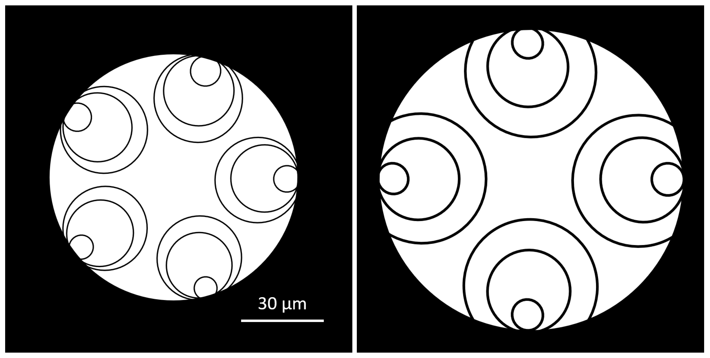
Figure 1. Structures of lowest-loss HCFs in 2024: 5T-DNANF (left) and 4T-DNANF (right) shown at the same scale. Glass is rendered in black and air in white.
Photonics 13 00494 g001
Figure 2. Structure of the first low-loss DNANF reported by Jasion et al. in 2022 [13]. Estimated truncation angle of nested tubes: 65°. Glass is rendered in black and air in white.
Photonics 13 00494 g002
Figure 3. Structures of 0.05 dB/km fibers reported in 2025: ST-HCF made by YOFC (left) and IT-4DNANF-B made by Linfiber (right). Glass is rendered in black and air in white.
Photonics 13 00494 g003
Figure 4. Statistical distribution of attenuation in production lengths of ST-HCF fiber [27].
Photonics 13 00494 g004
Figure 5. Decrease in record-low attenuation of NANF/DNANF fibers over time.
Photonics 13 00494 g005
Figure 6. (Left): Structure of 5-TNANF fiber, probably TNANF B [31]. (Right): A single triple-nested tube. Glass is rendered in black and air in white.
Photonics 13 00494 g006
Figure 7. Loss spectra of 5-tube DNANF fibers optimized for several wavelengths. Graph based on data from paper [22].
Photonics 13 00494 g007
Figure 8. Proposed DNANF structures with theoretical potential of achieving ultra-low confinement loss in the order of 0.001 dB/km. Left: Shaha et al. [34]. Right: Zhang et al. [35]. Glass is rendered in black and air in white.
Photonics 13 00494 g008
Figure 9. Loss spectrum of a 5-tube DNANF fiber with waterdrop-shaped tubes (Figure 8 right) (simulation) [35].
Photonics 13 00494 g009
Figure 10. Loss spectrum of record-low-loss 5T-DNANF made at University of Southampton and Microsoft Azure Fiber in 2024 [22] (Section 3.1). Absorption peaks, primarily of H2O and silanol (1330–1460 nm) and CO2 (1720–1830 nm), occupy ≈280 nm (40%) of the 700 nm wide spectrum shown. Main absorption peaks are very wide, and situation in this respect is worse than in SMFs before introduction of preform drying with hot chlorine gas in 1999. Courtesy of University of Southampton.
Photonics 13 00494 g010
Figure 11. Example of BDFA gain spectrum [50]. Bismuth-doped fiber was 470 m long, and input power equaled −23 dBm (5 μW). The OH absorption band is weaker when active fiber is shorter [51].
Photonics 13 00494 g011
Table 1. Comparison of latency and related parameters in HCF-NANF, other fibers and twisted-pair cables used in data centers and telecom networks (typical specifications). Data for OM4 fiber and air [12] are for the 850 nm wavelength; data for NANF and SMF are for 1550 nm.
Transmission mediumAirNANFSMF
G.652
MMF
OM4
Cat. 7
FTP 1
Effective refractive index (neff)1.0002741.0021.4681.4822
Velocity of propagation (VP) [c] 3,40.999720.99800.68120.67480.7900 5
Velocity of propagation (VP) [%c]99.97299.8068.1267.4879.00
Absolute VP [m/μs]299.71299.19204.22202.29236.84
Absolute unit latency [μs/km]3.33673.34234.89674.94344.2223
Notes: 1 Foiled twisted-pair cable: each pair is individually screened with metal foil. 2 This term is not used for metallic cables. 3 Frequently named “Nominal Velocity of Propagation” (NVP), can be given in %c. 4 c: speed of light in vacuum (299,792,458 m/s). 5 Manufacturing tolerances for VP in metallic cables are larger than for fibers: ±1–3%.
Table 2. Comparison of the record-breaking low-loss DNANF fibers developed in the UK [22,23] (fiber HCF2) and in China [24] (fiber #1).
Place of DevelopmentU. of Southampton and
Microsoft Azure Fiber
U. of Jinan and
Linfiber Technology
Fiber design5T-DNANF4T-DNANF
Length of fiber [km]15.04.2
Angle of truncation [°] 1≈100≈120
Transmission windowfirstsecond
Effective refractive index (neff)(no data)1.001
Attenuation at 1550 nm [dB/km] 20.091 ± 0.010.10 ± 0.02
Low-loss band [nm] 31292–1716≈1504–1654 4
Attenuation at 1320 nm [dB/km]0.122(no data)
Low-loss bandwidth [THz]54.3 + 9.518.1
CD at 1550 nm [ps/nm × km]3.2 (simulated)3 (measured)
HOMER(no data)4300
PMD [ps/√km]0.10(no data)
Main absorption bands [nm]1340–1450, 1720–18501570–1585, 1600–1620 3
Core diameter [μm]29.430.6
MSD [μm] 192114
Cladding (jacket) diameter [μm](no data)240
Notes: 1 Dimension estimated from fiber photographs. 2 Differences between multiple loss measurements were quite large. 3 Attenuation ≤ 0.14 dB/km; gas absorption peaks excluded. 4 Measurements performed between 1480 nm and 1650 nm.
Table 3. Comparison of lowest-loss HCFs developed in China at Linfiber [26] (fiber IT-4DNANF-B) and Yangtze Optical Fiber and Cable (YOFC) [27].
Place of DevelopmentUniv. of Jinan and
Linfiber Technology
YOFC and Optics Valley
Laboratory
Fiber designIT-4DNANFST-HCF
Length of fiber [km]409.1
Angle of truncation [°] 1≈70none
Transmission windowsecondsecond
Attenuation at 1550 nm [dB/km]0.052 ± 0.0040.050 ± 0.01
Attenuation at 1590 nm [dB/km]0.050 ± 0.004≈0.050
Low-loss band [nm] 2≈1450–1650 31450–1660
Low-loss bandwidth [THz]≥2526
CD at 1550 nm [ps/nm × km]≤5no data
PMD [ps/√km]≤0.20no data
Core diameter [μm]3830
MSD [μm] 313394 1
Cladding (jacket) diameter [μm]260no data
Notes: 1 Value estimated from fiber photographs. 2 Attenuation ≤ 0.14 dB/km; gas absorption peaks excluded. 3 Fiber loss was measured from 1450 nm to 1650 nm. Low-loss band extends to longer wavelengths.
Table 4. Record low-loss NANF and DNANF fibers reported since 2018.
Year of
Publication
Ref.Loss @ 1550 nm
[dB/km]
Fiber Design
2018[28]1.30 *6-NANF
2019[29]0.636-NANF
2020[30]0.286-NANF
2022[13]0.1745T-DNANF
2024[22]0.095T-DNANF
2025[26]0.052IT-4DNANF
2025[27]0.050ST-HCF
(*) Lowest loss measured at 1450 nm.
Table 5. Data of compact, medium-loss 5T-TNANF fibers developed in the UK [31].
Place of DevelopmentMicrosoft Azure
Fiber, UK
Microsoft Azure
Fiber, UK
Fiber design5T-TNANF5T-TNANF
Sample designationTNANF ATNANF B
Angle of truncation [°] 1(no data)≈100
Transmission windowfirstfirst
Attenuation at 1550 nm [dB/km]0.540.25
Low-loss band(s) with 1:2 ratio [nm] 21480–1700, 1290–13301440–1700
Lowest attenuation [dB/km]0.40 ± 0.02 (1660 nm)0.25 (1500–1550 nm)
HOMER190380
Absorption bands [nm]1340–1490 nm1340–1500 nm
Core diameter [μm]14.820.2
MSD [μm] 1(no data)88
Cladding diameter [μm]125145
Coating diameter [μm]250250
Notes: 1 Dimension estimated from photograph of the fiber. 2 Loss characterization performed up to 1700 nm, low-loss band extends farther.
Table 6. Data of low-loss 4T DNANF fibers for operation at 850 nm developed in the UK [32].
Place of DevelopmentMicrosoft Azure Fiber, UK
Fiber design5T-DNANF
Length of fiber [km]10.9
Angle of truncation [°] *≈80
Transmission windowfirst
Attenuation at 850 nm [dB/km]0.33
Low-loss band (≤0.5 dB/km) [nm]803–897
Lowest attenuation [dB/km]0.30 ± 0.02 at 860 nm
Low-loss bandwidth [THz]39.2
CD at 850 nm [ps/nm × km]2.3 (simulated)
Absorption bands [nm]None (770–900 nm)
Core diameter [μm] *24.5
MSD [μm] *81
(*): Dimension estimated from photograph of the fiber.
Table 7. Optical transmission bands standardized in ITU-T G. Supplement 39 [48].
DesignationFull NameWavelength Range [nm]
OOld1260–1360
EExtended1360–1460
SShort wavelength1460–1530
CConventional1530–1565
LLong Wavelength1565–1625
UUltra long wavelength1625–1675
Disclaimer/Publisher’s Note: The statements, opinions and data contained in all publications are solely those of the individual author(s) and contributor(s) and not of MDPI and/or the editor(s). MDPI and/or the editor(s) disclaim responsibility for any injury to people or property resulting from any ideas, methods, instructions or products referred to in the content.