1. Introduction
Bonding fused silica to metallic components—valued for their plasticity, toughness, and impact resistance—is critically important for aerospace engineering, precision optics, instrumentation, and advanced packaging technologies [
1,
2,
3]. For example, titanium foil is bonded to fluorine-doped tin oxide (FTO) glass to serve as a substrate for growing TiO
2 nanotubes in dye-sensitized solar cells [
4]. Conventional joining methods for dissimilar materials, such as brazing [
5], mechanical fastening [
6], adhesive bonding [
7], and solid-state bonding [
8], each have inherent limitations. Brazing effectiveness is compromised by the poor wettability of glass surfaces, which hinders filler metal flow [
9]. Adhesive bonding often results in insufficient mechanical strength and long-term degradation, especially under thermal cycling. Mechanical fastening can damage brittle substrates via localized stress concentration. Solid-state bonding typically requires high temperature and/or high pressure, inducing interfacial thermal stress and fracture [
6,
8]. Consequently, these methods face challenges in achieving high-strength, durable glass–metal joints while maintaining process simplicity.
Laser welding offers a precise, localized, and contact-free joining approach [
10,
11,
12,
13]. However, conventional laser welding of transparent materials typically relies on linear absorption mechanisms, where the material’s inherent absorption coefficient dictates energy transfer. Due to the low linear absorption of transparent materials at common laser wavelengths, this often necessitates depositing an absorbing interlayer to effectively couple energy at the interface [
14,
15]. This approach adds process complexity and can compromise optical performance. In contrast, ultrafast lasers, characterized by pulse durations in the femtosecond (fs) to picosecond (ps) range, achieve extremely high peak intensities, typically reaching 10
13 W/cm
2 or even higher depending on focusing conditions. These intense pulses enable nonlinear absorption mechanisms in transparent dielectrics, such as multiphoton absorption (MPA) and avalanche ionization. These mechanisms lead to localized energy deposition and subsequent phase transitions, enabling direct bonding of transparent materials without the need for interlayers [
16,
17]. The use of non-diffracting beams with a long focal depth further enables nanoscale near-field ablation, opening a novel approach for non-contact joining of transparent materials [
18].
Ultrafast laser microwelding was first demonstrated by Tamaki et al. in 2005 at Osaka University, where they achieved localized melting and welding of transparent glass [
19]. Watanabe et al. extended this to direct welding between borosilicate glass and fused silica, reporting joint strengths near 16 MPa [
20]. By 2008, Horn et al. had broadened the material scope to include joining transparent glass to opaque silicon [
21]. More recent advances in ultrafast laser energy scaling and higher repetition rates have enabled glass–steel bond strengths exceeding 100 MPa [
22,
23]. Despite these advances, most high-strength ultrafast laser joints rely on optical contact between mating surfaces, which demands sub-nanometer surface roughness and minimal gap—a condition difficult to maintain in practical manufacturing. Ultrafast laser welding under non-optical-contact conditions has therefore become a key research focus. For example, Jia et al. developed a multi-scan picosecond laser process that could bond soda-lime glass across gaps of up to approximately 5 μm, but achieved joint strengths limited to around 6.5 MPa [
24].
For the titanium (Ti)-glass system, existing studies have predominately focused on welding TC4 titanium alloy (Ti-6Al-4V) to fused silica. For instance, Li et al. [
25] investigated the effect of pulse energy on the microstructure and mechanical properties of non-optical-contact femtosecond laser welding of quartz glass and TC4 alloy, achieving a shear strength of 10.4 MPa under optimized conditions. Wang et al. [
26] further explored the effects of defocus distance and weld spacing on quartz glass-TC4 alloy joints, reporting a maximum shear strength of 14.4 MPa. These studies, however, primarily utilized TC4 alloy and often employed millijoule (mJ)-level pulse energies (e.g., 0.3 mJ [
25,
26]) for welding. While such high-energy pulses are capable of producing strong joints, they also tend to induce pore defects and interfacial instability due to the substantial difference in coefficient of thermal expansion (CTE) between fused silica (≈0.59 × 10
−6 K
−1 [
20]) and titanium (≈8.6 × 10
−6 K
−1 [
27]). Furthermore, certain techniques to enhance Ti-glass welding, such as those by Wang et al. [
28] using magnetron-sputtered TiO
2 coatings or Li et al. [
29] employing thermal oxidation or anodization of the TC4 surface, typically require surface pretreatment or interlayers, which increase process complexity and may compromise optical performance or long-term stability.
In contrast, direct femtosecond (fs) laser microwelding of pure titanium (Ti) foil and fused silica—especially at microjoule (μJ)-level pulse energies and without interlayers or surface pretreatments—has rarely been reported. Pure Ti offers unique advantages in applications requiring lightweight design, corrosion resistance, and high-purity materials, such as in aerospace engineering and electronic packaging [
30]. This study, for the first time, demonstrates direct fs laser welding of pure Ti foil to fused silica using μJ-level pulses under ambient conditions, without the need for interlayers or surface pretreatments. This approach significantly simplifies the process while maintaining high joint quality. We systematically investigated the influence of laser parameters on joint shear strength, characterized the weld morphology, analyzed the elemental distribution at the interface, and determined the interfacial chemical bonding states using X-ray photoelectron spectroscopy (XPS). The results reveal that elemental interdiffusion, mechanical interlocking, and interfacial chemical reactions collectively contribute to reliable joint formation. Furthermore, a preliminary hermeticity test was conducted to evaluate the sealing capability of the welded structure. This study provides an efficient, stable, and novel solution for joining fused silica and pure Ti foil, eliminating the need for complex surface modifications or high-energy pulses, and thus expanding the scope of dissimilar material joining for various industrial applications. A comprehensive comparison of the laser welding conditions used in this work with those reported in previous studies is presented in
Table 1.
2. Materials and Methods
The welding substrates were fused silica (30 mm × 20 mm × 1 mm) and 99.99% pure titanium foil (40 mm × 20 mm × 0.2 mm). Prior to welding, the specimens were ultrasonically cleaned in anhydrous ethanol and deionized water for 10 min each, followed by air drying.
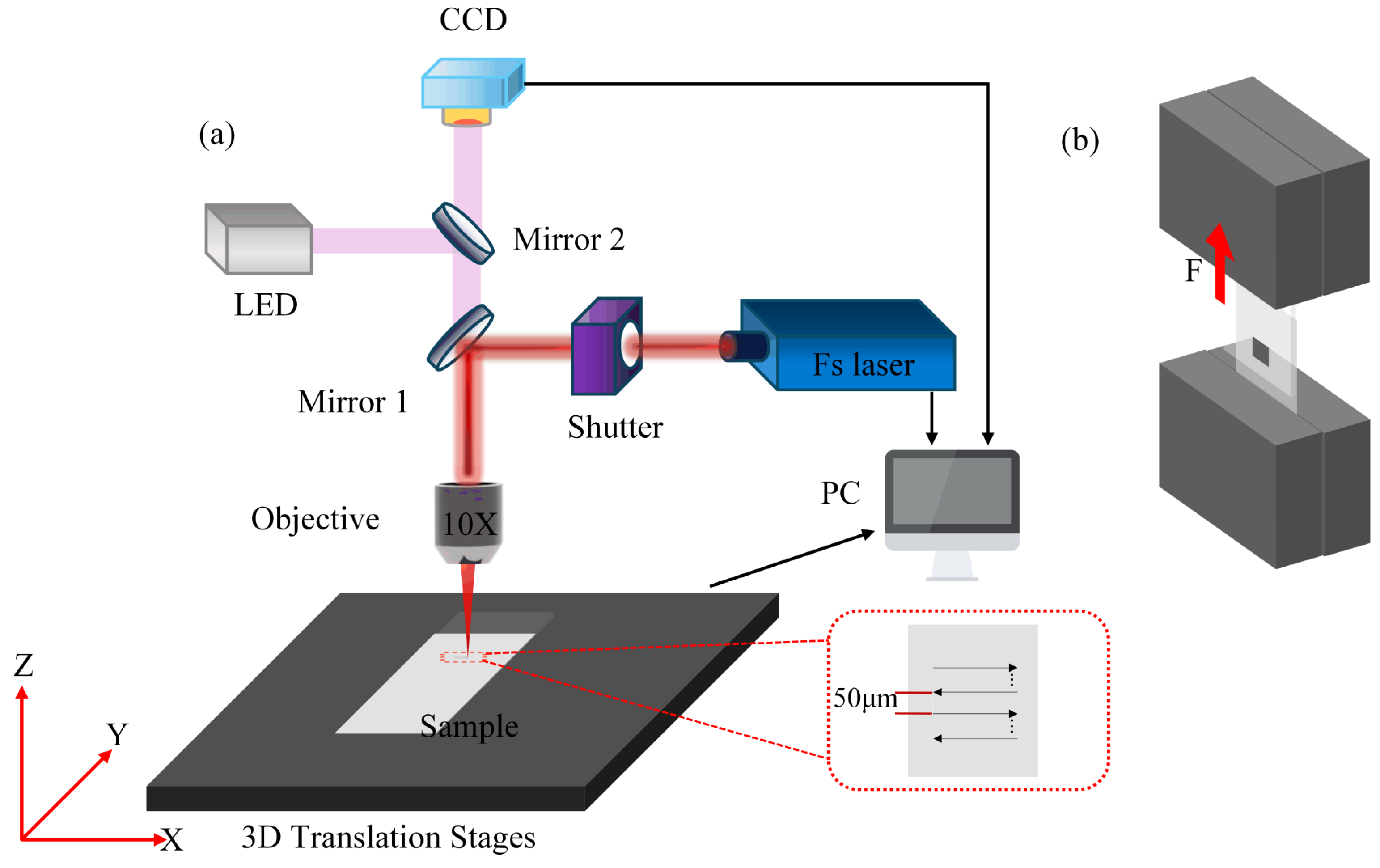
The laser source used was a Yb:KGW ultrafast laser system (Pharos, Light Conversion Ltd., Vilnius, Lithuania) with a pulse duration adjustable from 300 fs to 10 ps. The laser beam was focused at the interface between the fused silica and titanium foil via a 10× objective lens (NA = 0.26, MY10 802). The beam exhibited a Gaussian intensity profile, and the diameter of the focused spot at the 1/e2 level was approximately 10.2 μm. Based on the laser power of 2 W and a repetition rate of 100 kHz, the single pulse energy was calculated to be 20 μJ.
The fused silica substrate was placed in contact with the Ti foil, and fixture pressure was applied to ensure stable contact during the welding process. The laser beam was focused precisely at the interface between the Ti foil and fused silica, while the scanned area was processed in a bidirectional raster pattern with a line spacing of 50 μm, covering a rectangular area of 2 mm × 2 mm. To avoid potential heat accumulation effects (which may lead to glass cracking at μJ-level pulse energies and high repetition rates), each welded area was scanned only once (single-pass scanning).
After welding, the shear strength of the joints was evaluated using a universal testing machine. The shear strength σ was calculated as σ = F/S, where F represents the shear force measured during testing (
Figure 1b) and S represents the welded area. In this work, the welding area S was maintained at 2 mm × 2 mm. A vertically upward load was applied at a constant displacement rate of 1 mm/min.
Following the shear tests, the fracture morphology on the Ti foil side was examined by scanning electron microscopy (SEM). Additionally, the elemental distribution in the fractured region was analyzed using energy-dispersive X-ray spectroscopy (EDS), and the chemical bonding states formed during welding were further characterized by X-ray photoelectron spectroscopy (XPS).
3. Results and Discussion
3.1. Effect of Laser Welding Parameters
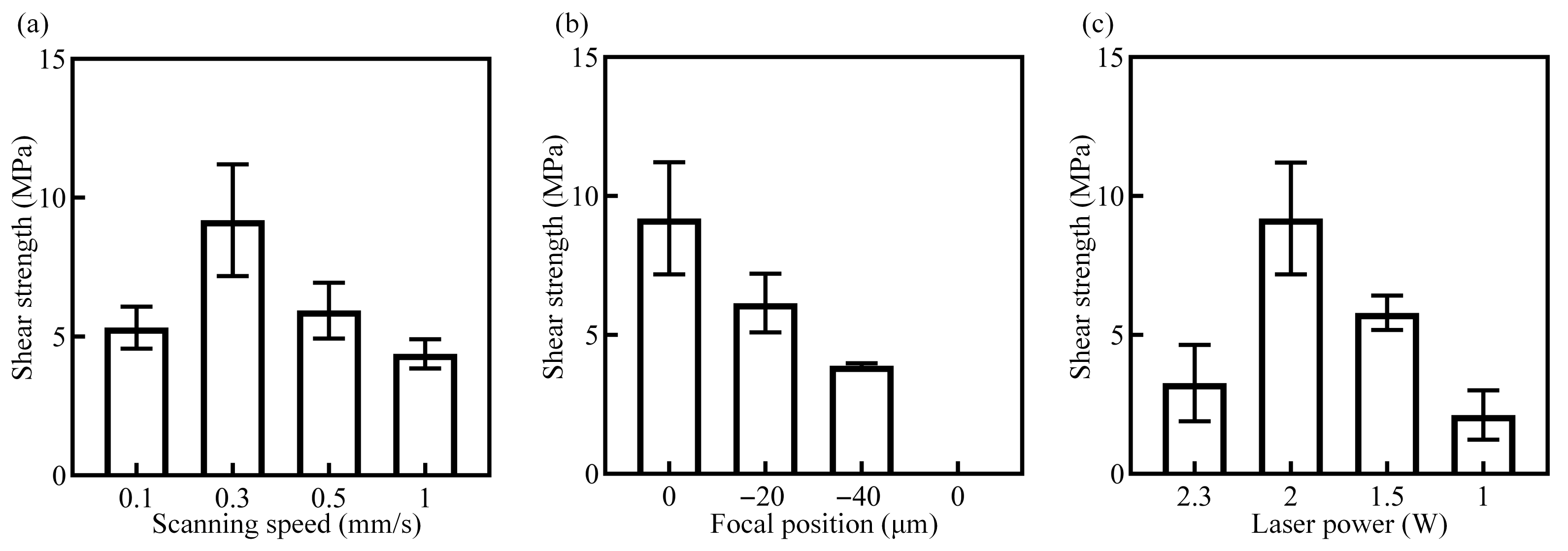
All experiments were repeated three times, and the shear strength values are presented as mean ± standard deviation (SD), as indicated by the error bars in
Figure 2. The position of the laser focus relative to the interface between fused silica and Ti foil is denoted as ΔZ, where ΔZ = 0 indicates the laser focus is precisely at the interface, while ΔZ < 0 denotes a downward defocus into the Ti foil. Since the laser must penetrate the glass to reach the interface, positive defocus (ΔZ > 0, upward shift) places the focus inside the glass, thus preventing effective energy deposition at the interface. Therefore, this study focused exclusively on the defocusing range of ΔZ ≤ 0.
Figure 2a presents the relationship between joint shear strength and scanning speed, with laser power, defocusing distance, and repetition rate fixed at 2 W (20 μJ), 0 μm, and 100 kHz, respectively. The highest shear strength of 9.19 MPa was achieved at a scanning speed of 0.3 mm/s. At higher scanning speeds, the laser energy absorbed by the Ti foil was reduced, resulting in weaker thermal effects. Consequently, the adhesion between molten glass and the Ti foil diminished and the shear strength decreased. Conversely, very low scanning speeds caused excessive heat accumulation, which led to glass cracking, further reducing joint strength.
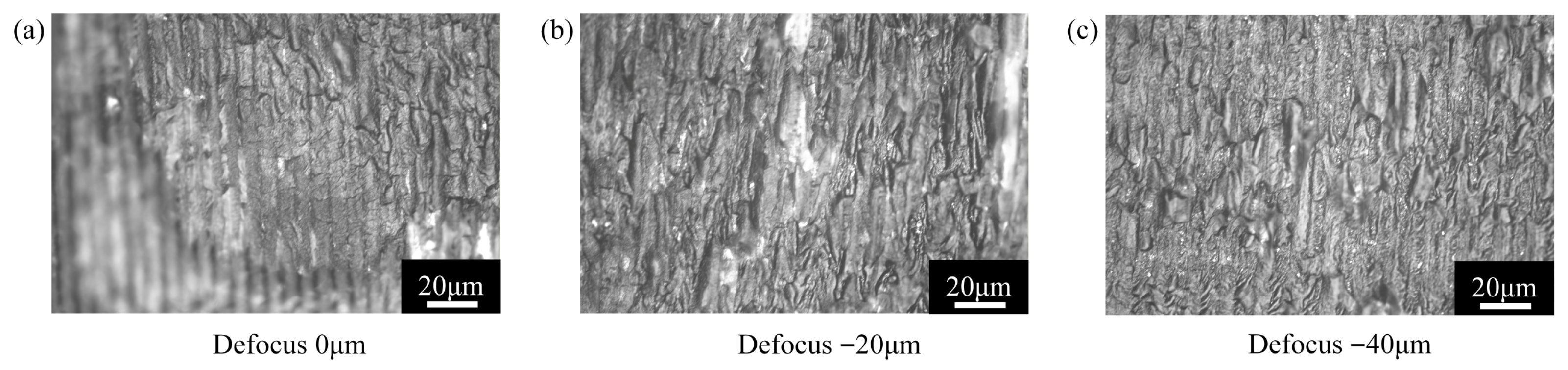
Figure 2b illustrates the dependence of shear strength on defocusing distance ΔZ, with laser power, scanning speed, and repetition rate fixed at 2 W (20 μJ), 0.3 mm/s, and 100 kHz. The maximum joint strength was observed at zero defocus (ΔZ = 0). When the defocus distance decreased below zero, the laser energy density on the Ti foil surface was lower than that at the focal point, leading to insufficient localized heating and thus a reduction in shear strength. Fracture morphology analysis corroborated these results (
Figure 3).
At ΔZ = 0 μm and ΔZ = −20 μm (
Figure 3a,b), substantial quantities of solidified fused silica adhered to the Ti surface after fracture testing. In contrast, at ΔZ = −40 μm (
Figure 3c), minimal molten silica was observed on the Ti foil surface, indicating limited interfacial melting and significantly lower joint strength. The higher single-pulse energy density at ΔZ = 0 μm facilitated more extensive glass melting compared to ΔZ = −20 μm, accounting for the greater shear strength observed under zero-defocus conditions. Additionally, the abundance of glass residues at the interface confirmed that fracture predominantly occurred within the fused silica, close to the interface zone.
Figure 2c shows the variation in shear strength with laser power, while other process parameters (scanning speed, focal position, and repetition rate) were fixed at 0.3 mm/s, 0 μm, and 100 kHz, respectively. At laser powers below 1 W (10 μJ), insufficient energy was delivered to melt and bridge the interface gap, resulting in weak joint formation. The maximum shear strength of 9.19 MPa was achieved at 2.0 W, establishing this as the optimal power level. Beyond this power level (e.g., 2.3 W), excessive energy caused glass cracking and severe ablation of both the Ti foil and fused silica, which compromised joint integrity and reduced shear strength.
Based on the above results, the optimal process parameters for fs laser welding of fused silica and Ti foil are as follows: laser power of 2.0 W, defocus distance of 0 μm, scanning speed of 0.3 mm/s, and repetition rate of 0.1 MHz. Under these conditions, the maximum shear strength of 9.19 MPa was achieved. When compared to existing studies on glass–metal dissimilar welding strengths, Watanabe et al. reported shear strengths of approximately 16 MPa for borosilicate glass to fused silica under specific conditions [
20], Jia et al. obtained shear strengths of around 6.5 MPa for soda-lime glass across gaps [
24], and Li et al. achieved values between 10 and 15 MPa for TC4 alloy bonded to quartz glass [
25]. In contrast, this study achieved moderate-to-high joint strength without the use of interlayers or surface pretreatments, illustrating that direct μJ-level femtosecond laser welding of pure titanium foil to fused silica offers promising application potential, especially in scenarios emphasizing process simplicity.
3.2. Weld Seam Morphology
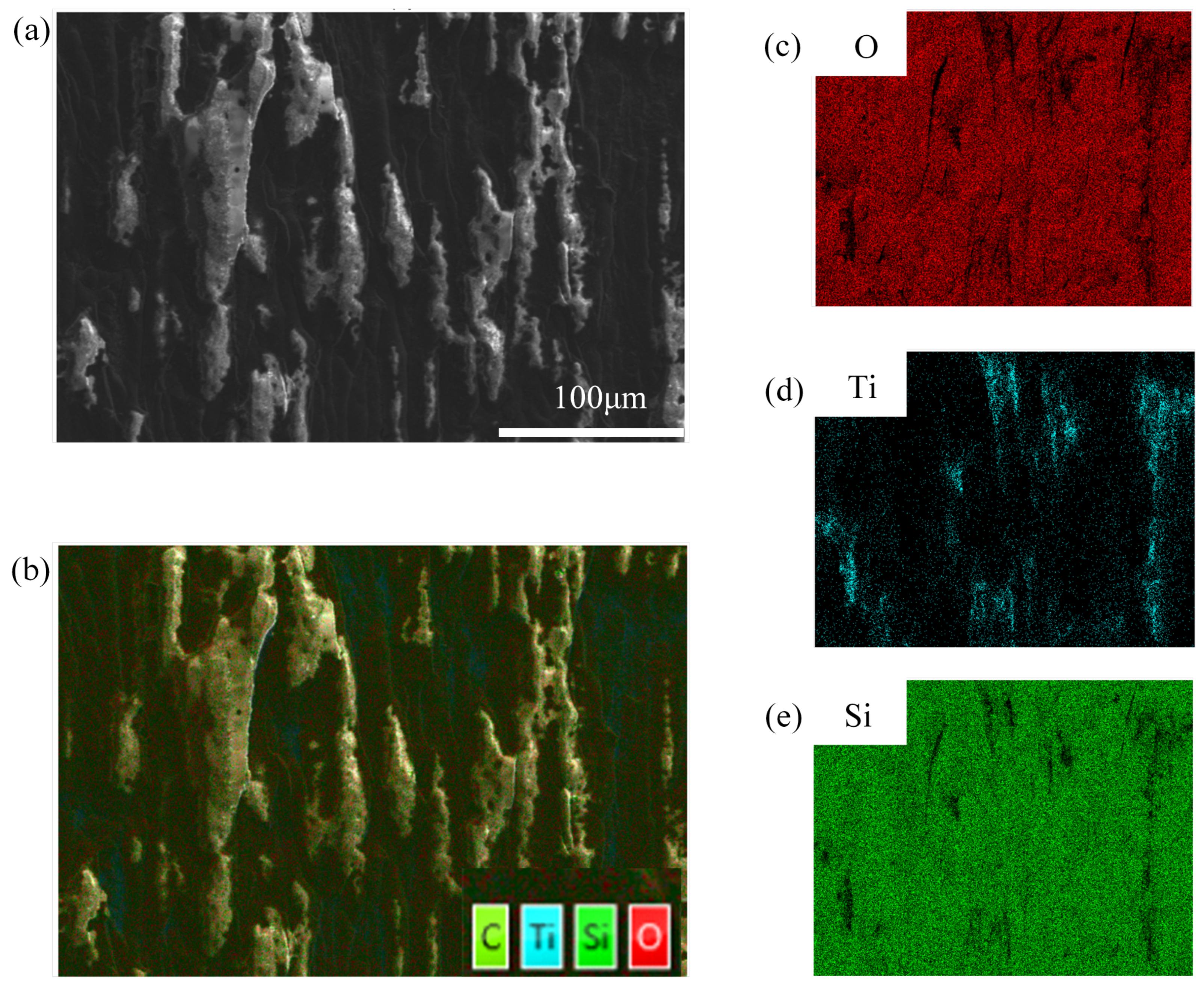
Figure 4 presents SEM micrographs and EDS elemental maps of the fracture surface on the Ti foil side after shear testing. The local morphology of the welded zone (
Figure 4a) reveals distinct weld seam features along with numerous non-periodically arranged surface structures. Elemental maps (
Figure 4b–e) demonstrate the presence of significant amounts of fused silica residue adhering to the Ti foil after fracture. The non-periodic features were coated with a glassy material, further confirming the adhesion of molten glass to the Ti foil during welding.
These observations indicate that fracture occurred predominantly within the fused silica, close to the interface. This phenomenon can be attributed to two primary factors. First, fused silica is intrinsically brittle: under mechanical loading, the presence of secondary phase particles (TiSi
2 and TiO
2, as identified by XPS) at the interface creates local stress concentration, causing the glass to fracture before reaching its theoretical strength. Second, the strong interfacial bonding between fused silica and Ti foil [
25] not only ensures effective joint formation but also directs fracture behavior into the weaker material (fused silica).
The fracture surface exhibited typical brittle fracture features, such as conchoidal patterns, which indicate that cracks propagated primarily within the glass matrix. Furthermore, in some regions, traces of molten glass peeling off the Ti foil surface were observed, which may be attributed to local non-uniformity in interfacial bonding strength or the presence of minor defects. However, cohesive fracture within the glass matrix predominated overall, suggesting consistent interfacial performance.
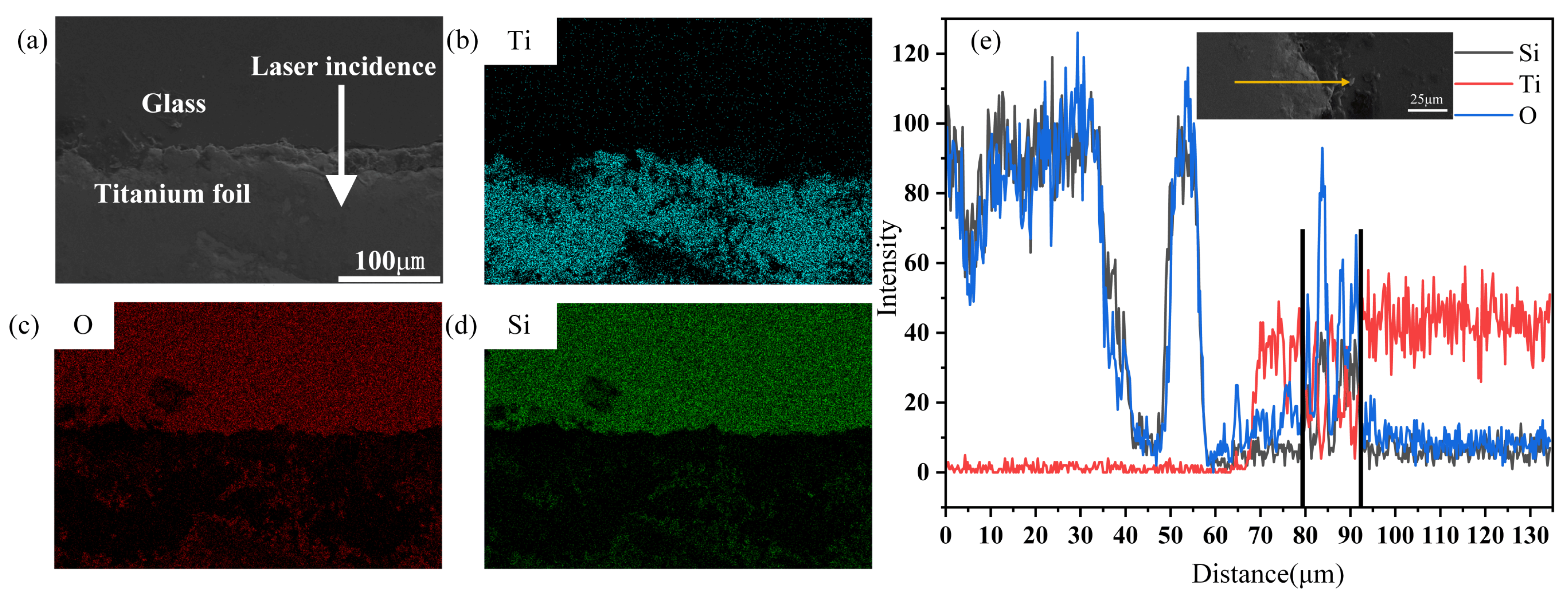
Figure 5a illustrates a cross-sectional view of the weld seam, highlighting the interfacial region between fused silica (upper region) and Ti foil (lower region). The image reveals pits formed by molten glass penetrating into the Ti foil, while Ti was also observed to intrude into the glass, thus forming a mechanically interlocked and intermixed interface. During laser irradiation, the volumetric expansion of molten materials created considerable internal pressure, which ejected molten glass from the lower surface and molten titanium from the upper surface, effectively filling the interfacial gap between the two substrates. As shown in
Figure 5b–d, Ti, O, and Si were distributed throughout the welding zone; although their concentrations remained relatively low, mutual elemental penetration within the weld region was clearly evident. EDS line scanning along the yellow arrow in
Figure 5e revealed an elemental diffusion depth of approximately 13 μm (spanning the region between the two black lines). The combination of mechanical interlocking and elemental interdiffusion was determined to be a key factor contributing to the weld joint’s stability.
Following high-temperature melting, the remelted zone cooled and contracted rapidly, creating defects at the interface between the remelted zone and the original glass substrate. As shown by the O and Si profiles in
Figure 5e, these defects coincided with pronounced drops in oxygen and silicon content, with no detectable elemental interdiffusion into titanium observed in these regions. Such regions represented weak points within the glass-Ti joint and were more likely to fracture under applied stress. This highlights the importance of precise control over laser parameters to minimize interfacial defects and ensure optimal joint strength.
3.3. Microstructure and Interfacial Chemistry
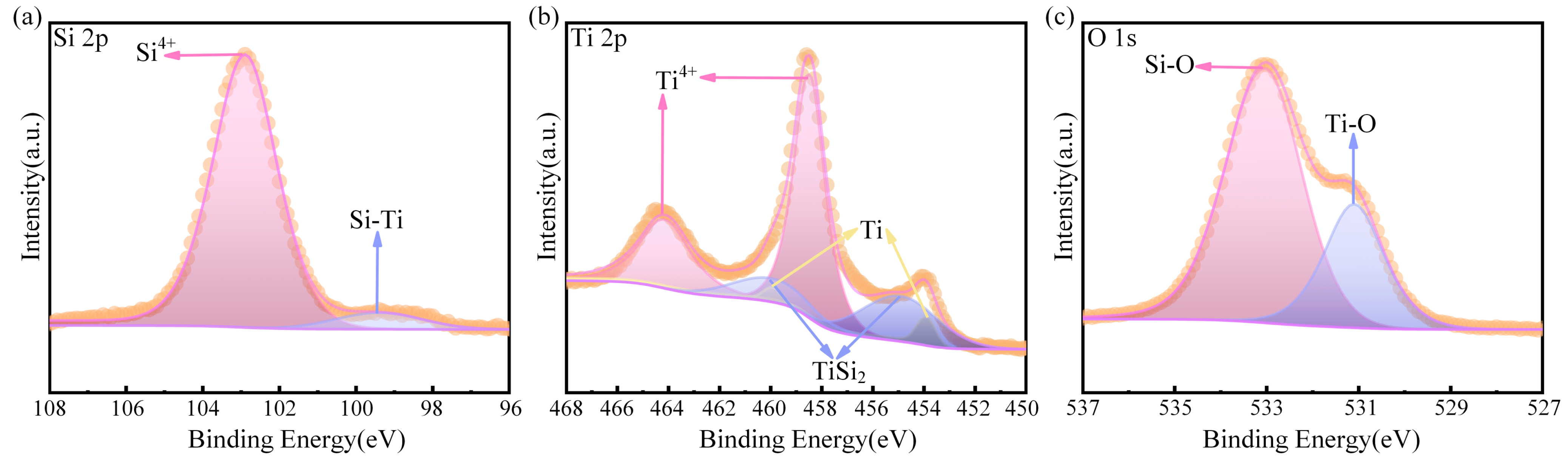
To identify the phases present at the weld joint, the fracture surface on the Ti foil side was analyzed by XPS, and the results are summarized in
Figure 6. All binding energies were calibrated using the C 1s peak at 284.8 eV, which corrects for potential charge-related offsets and surface-state variations.
Figure 6a shows the Si 2p XPS spectrum from the welding interface. The peak at 103 eV corresponds to the Si
4+ 2p
3/
2 state typically associated with SiO
2 [
31,
32]. Additionally, a distinct peak at 98.4 eV was detected, which correlates to the Si-Ti bond [
33], confirming the interaction between silicon from the fused silica and Ti from the foil.
Figure 6b presents the Ti 2p XPS spectrum, where three spin–orbit peaks (2p
3/
2 and 2p
1/
2) were identified. Peaks at 453.9 eV and 459.9 eV correspond to metallic Ti (Ti
0), while 458.5 eV and 464.2 eV are attributed to Ti
4+ in TiO
2 [
34]. Notably, peaks at 454.9 eV and 460 eV were assigned to TiSi
2, indicating the formation of Ti silicide [
35].
Figure 6c depicts the O 1s XPS spectrum. After peak fitting, two distinct peaks emerged: one at 532 eV attributed to the Si-O covalent bond in fused silica, and the other at 530 eV, corresponding to the Ti-O bond in Ti oxide [
36,
37,
38].
These results unequivocally confirm that interfacial chemical reactions occurred during welding, resulting in the simultaneous formation of titanium silicide (TiSi2) and titanium oxide (TiO2). Collectively, these observations validate the overall interfacial reaction: 2SiO2 + 3Ti → TiSi2 + 2TiO2.
When a fs laser was focused at the interface between fused silica and Ti foil, the temperature rose rapidly (>750 °C). Under such high temperatures, the reaction between Ti and SiO
2 was thermodynamically spontaneous, with a negative Gibbs free energy (ΔG), indicating the feasibility of the reaction [
39]. The high peak intensity of the fs laser rapidly heated the Ti foil surface and induced nonlinear absorption in the fused silica. At the interface, Ti atoms acted as a reducing agent for SiO
2. The overall reaction proceeded in two steps: (i) reduction of SiO
2 by Ti, extracting oxygen to form TiO
2 and releasing elemental Si; (ii) silicidation, in which the released Si diffused into the molten Ti and reacted at high temperature to form TiSi
2 [
40,
41]. The preferential formation of TiSi
2 over other silicides (e.g., Ti
5Si
3) may be attributed to reaction kinetics, local elemental concentrations, and the thermodynamic stability of TiSi
2 at high temperatures. TiSi
2, as an intermetallic compound, possesses good electrical conductivity and thermal stability, and its formation enhances metal-ceramic bonding at the interface, reduces interfacial energy, and thus improves the overall strength and stability of the joint. The interaction with the fs laser resulted in the breaking of metallic and Si-O bonds, and the formation of Si-Ti and Ti-O bonds due to mixing of redeposited glass and Ti.
3.4. Hermeticity Test
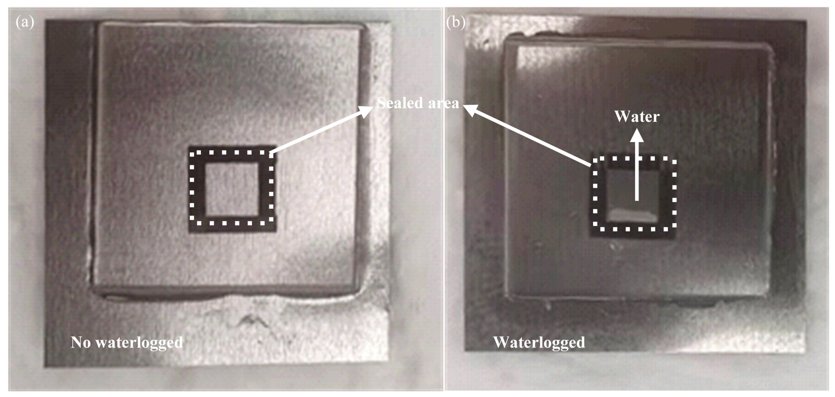
To evaluate the sealing performance of the fs laser-welded Ti foil/fused silica structures, hermeticity tests were conducted using a square sealed cavity with dimensions of 5 mm × 5 mm, fabricated during laser processing. The welded samples were immersed in water for 24 h, and the quality of the seal was assessed by observing potential water ingress.
Figure 7 illustrates the macroscopic morphologies of the sealed samples after immersion testing. The square sealed region in
Figure 7a remained intact with no visible water penetration, demonstrating excellent hermeticity. In contrast,
Figure 7b revealed water ingress within the sealed area, attributed to process-induced defects, such as micro-cracks or unfused regions, which compromised sealing performance.
Although the 24 h water immersion test serves as a qualitative feasibility evaluation for hermeticity, it is noteworthy that quantitative benchmarks for glass–metal seals, particularly in electronic packaging applications, necessitate helium leak rates approximating 10
−8–10
−9 mbar·L/s as per standards such as MIL-STD-883 [
42,
43,
44].
Future work will incorporate quantitative hermeticity characterization, including helium leak rate measurements using mass spectrometry, as well as long-term aging tests to further validate and improve the sealing performance of femtosecond laser-welded Ti foil/fused silica structures.
3.5. Welding Mechanism at the Ti Foil/Fused Silica Interface
When focused through an objective lens, fs laser pulses achieved extremely high peak intensities in the focal region. Based on the experimental parameters (pulse energy: 20 μJ, pulse duration: 300 fs, focused spot diameter: 10.2 μm at 1/e
2), the peak intensity was estimated to be approximately 8.2 × 10
13 W/cm
2, corresponding to a fluence of about 24.5 J/cm
2. This intensity significantly exceeded the nonlinear ionization threshold for fused silica (~10
13 W/cm
2) [
45], thereby inducing distinct interaction mechanisms in the two materials. Intense laser irradiation rapidly elevated the local temperature at the Ti foil/fused silica interface far beyond the melting points of both materials (Ti: 1668 °C; fused silica: 1720 °C) [
20]. This extreme thermal environment caused localized melting and facilitated the mutual diffusion of molten species at the interface, thereby forming a reliable welded bond.
In fused silica, a wide-bandgap dielectric material [
46], nonlinear optical ionization occurred under the influence of the fs laser pulses. Seed electrons generated through multiphoton absorption multiplied rapidly via avalanche ionization [
45,
47,
48], forming dense plasma. At high repetition rates (e.g., 100 kHz), cumulative heating reduced the ablation threshold, promoting melt pooling [
49]. Energy transfer via electron–phonon coupling raised the lattice temperature, melting the fused silica. Local pressure gradients caused by melting drove the molten glass into the interfacial gap, where it further interacted with molten Ti and cleaved Si-O bonds to facilitate robust bonding at the interface.
In the Ti foil, its high free-electron density allowed for efficient energy absorption through free-electron heating and photoionization [
50]. The rapid increase in electron temperature triggered collisional ionization and phase explosions within picoseconds, ejecting high-temperature gaseous species and molten droplets. This asymmetric energy absorption and deposition between fused silica and Ti caused unique melt pool dynamics, as observed in
Figure 5a. The molten Ti, O, and Si atoms interdiffused at the interface, forming a mechanically interlocked bond. XPS analysis confirmed the formation of TiSi
2, which highlights the hybrid welding mechanism that improved the joint’s strength and stability.
During continuous multi-pulse irradiation, a transient plasma composed of energetic atoms, clusters, and droplets from both materials was sustained. This plasma propagated along the laser incidence direction, acting as a dynamic shield that modulated energy delivery. Consequently, the longitudinal energy distribution across the interface became non-uniform until the plasma dissipated into regions of lower laser intensity. These plasma dynamics played a crucial role in determining the morphology of the final weld seam and the interfacial structure.
Residual stress is an inevitable consequence of laser welding dissimilar materials due to the significant mismatch in the CTE between titanium and fused silica. This stress was primarily distributed within the weld seam and the adjacent HAZ of both materials. At the interface, the residual stress exhibited a distinct asymmetric distribution: tensile stress dominated on the fused silica side due to the constrained contraction of molten silica during rapid cooling, while compressive stress concentrated on the Ti side, resulting from plastic deformation induced by thermal expansion and cooling [
25]. Furthermore, the rapid solidification and non-uniform shrinkage of the molten region promoted stress localization within the interfacial diffusion layer, which is characteristic of laser-modified glass materials [
51].
Since most laser energy was absorbed by the upper transparent fused silica layer, its inherently low fracture toughness made it prone to brittle fracture and microcrack initiation under transient thermal stresses during rapid cooling cycles. These microdefects often formed at the interface between the remelted zone and the original substrate and acted as stress concentrators under applied mechanical loads. This ultimately constrained the joint strength, which was dependent on the fracture toughness of fused silica and the integrity of the remelted interface. Precise control over laser parameters, such as pulse energy and repetition rate, is essential to mitigate defect formation and optimize joint performance.
4. Conclusions
In this study, direct welding of pure titanium (Ti) foil to fused silica was successfully achieved using microjoule (μJ)-level femtosecond (fs) laser pulses under ambient conditions, without any interlayer or surface pretreatment. This addressed a research gap in achieving high-strength joining of pure Ti foil and fused silica—i.e., dissimilar materials—under low-energy, additive-free conditions, and provided a feasible approach for welding materials with a large coefficient of thermal expansion (CTE) mismatch (approximately 15-fold difference). Through systematic optimization of the laser parameters, a maximum shear strength of 9.19 MPa was obtained at a laser power of 2.0 W (20 μJ), a scanning speed of 0.3 mm/s, and zero defocus. Microstructural characterization revealed that laser-induced material mixing and elemental interdiffusion occurred within the welding region, forming an interdiffusion zone approximately 13 μm thick, accompanied by mechanical interlocking. X-ray photoelectron spectroscopy (XPS) confirmed the occurrence of interfacial chemical reactions, with the formation of TiSi2 and TiO2. The synergistic effect of chemical bonding and elemental interdiffusion is considered the primary mechanism responsible for the reliable joint. Furthermore, a 24 h water immersion test demonstrated that the fs laser-welded square cavity exhibited excellent hermeticity with no water ingress, indicating its potential for encapsulation applications. Quantitative hermeticity characterization (e.g., helium leak rate measurements) will be pursued in future work to further validate the sealing reliability. This work offers a novel, efficient, and stable solution for joining fused silica and pure Ti foil, eliminating the need for complex surface pretreatments or high-energy pulses, thereby expanding the scope of dissimilar material joining for industrial applications.