Article

Tabletop 3D Display with Large Radial Viewing Angle Based on Panoramic Annular Lens Array

School of Instrumentation and Optoelectronic Engineering, Beihang University, Beijing 100191, China
*
Author to whom correspondence should be addressed.
Photonics 2025, 12(5), 515; https://doi.org/10.3390/photonics12050515
Submission received: 6 April 2025 / Revised: 10 May 2025 / Accepted: 12 May 2025 / Published: 21 May 2025
(This article belongs to the Special Issue Research on Optical Materials and Components for 3D Displays)

Abstract

Tabletop 3D display is an emerging display form that enables multiple users to share viewing around a central tabletop, making it promising for the application of collaborative work. However, achieving an ideal ring-shaped viewing zone with a large radial viewing angle remains a challenge for most current tabletop 3D displays. This paper presents a tabletop 3D display based on a panoramic annular lens array to realize a large radial viewing angle. Each panoramic annular lens in the array is designed with a block-structured panoramic front unit and a relay lens system, enabling the formation of a ring-shaped viewing zone and increasing the radial angle of the outgoing light. Additionally, the diffusion characteristics of the optical diffusing screen component are analyzed under large angles of incidence after light passes through the panoramic annular lens array. Then, a method for generating the corresponding elemental image array is presented. The results of the simulation experiments demonstrate that the viewing range is improved to −78.4–−42.2° and 42.6–78.9°, resulting in a total radial viewing angle of up to 72.5°, and the proposed 3D display can present a 360° viewable 3D image with correct perspective and parallax.

1. Introduction

Tabletop three-dimensional (3D) display is one of the 3D display forms that provides realistic 3D images for viewers standing or sitting around a central tabletop and supports multi-user collaborative work and interaction [1,2]. The application fields, such as electronic sand table and multi-user conferencing, need the tabletop 3D display to revolutionize the existing plane experience of two-dimensional (2D) display. An ideal tabletop 3D display should reconstruct correct light rays in a 360° viewing zone, and the whole viewing zone should be a ring [3,4]. Additionally, the viewing angle in the radial direction should be sufficiently large to ensure that viewers located at different positions along the radial direction can simultaneously perceive correct 3D images, with different viewers observing different sides of the 3D model. Here, the radial viewing angle should be discontinuous since the viewing zone right above the tabletop is invalid for the form of the tabletop display [5]. Some 3D displays that utilize a 360° directional micro prism array or a projector array with multiple high-refresh-rate projectors are suitable for realizing the tabletop 3D display format [6,7,8,9]; however, there is usually no perspective and parallax in the radial direction due to the limited information provided by these components.
Integral imaging is a light field 3D display that provides 3D images with full parallax, which is suitable for realizing the radial perspective and parallax in the tabletop 3D display [10,11,12,13,14,15,16,17]. A large radial viewing angle while maintaining correct perspective and parallax can be achieved by optimizing the core component, the lens array, to a triplet lens array or a compound lens array [18,19], and the radial viewing angle is up to −34.4° to 34.3° in the case of a large display size of 43.5 inches. However, the radial viewing angle in these displays is continuous, meaning that the viewers positioned at 0° still perceive the reconstructed light rays, resulting in a waste of the already limited angular information. The lens array incorporating a specialized type of lens, the conical lens, enables a discontinuous radial viewing angle [20], and the whole viewing zone has a ring shape. The radial viewing angle on each side is 15°, ranging from ±20° to ±35°, but it should be further improved to meet the viewing requirement of more viewers with different positions along the radial direction. In addition to optimizing the component of the lens array, the improved arrangement of the pixels in the elemental image array presented on the 2D display panel also provides a pathway for the ring-shaped viewing zone [21,22]. The effective pixels of each elemental image are distributed as an annular sector to compose a whole ring-shaped viewing zone by combining the time-division multiplexing scheme. Large radial viewing angle in this scheme is realized depending on the large field of view of the compound lens array, while no special type of lenses is needed. However, the system is complex and bulky due to the introduction of a rotating mechanism and the time-division multiplexing scheme. A large and discontinuous viewing angle in the radial direction with correct perspective and parallax is still a challenge.
In this paper, we propose a tabletop 3D display with a large radial viewing angle based on integral imaging display. A specialized type of lens array, the panoramic annular lens array, is designed and optimized to significantly enlarge the radial viewing angle and make the viewing angle discontinuous. Since the key characteristic of the panoramic lens is that it produces a flat annular image of the entire 360° surrounding pixels around the optical axis of the lens without the need for any scanning unit or stitching task, the ring-shaped viewing zone is possible. An optical diffusing screen is positioned above the panoramic annular lens array to address the gap issue between adjacent panoramic annular lenses, and its diffusion characteristics under large angles of incidence are analyzed. Additionally, we propose a method for generating the corresponding elemental image array. A simulation experiment is performed to demonstrate the effectiveness of the 360° viewing effect and the large radial viewing angle with correct perspective and parallax.

2. Methods

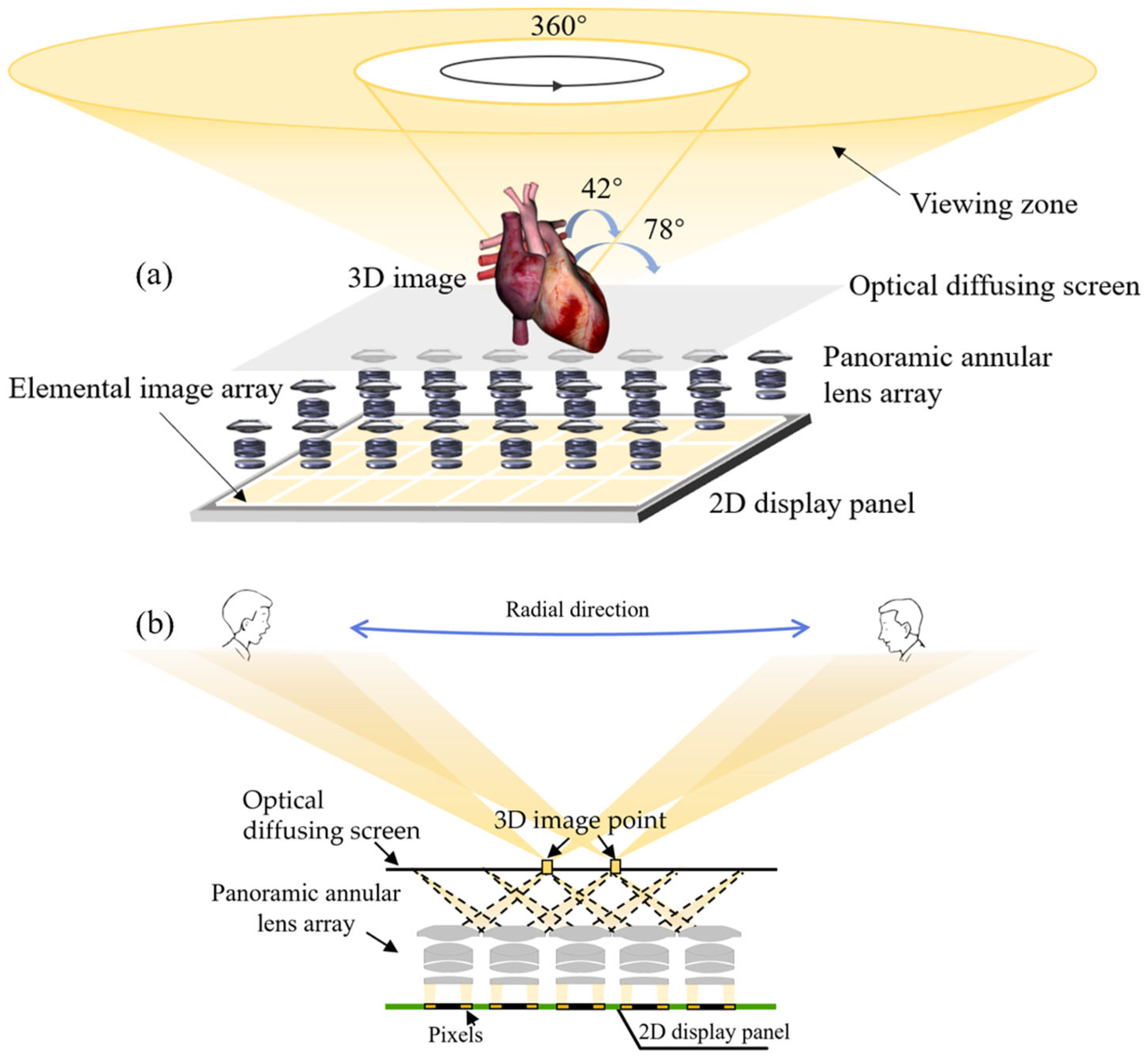
2.1. Configuration of the Tabletop 3D Display

Figure 1a shows the configuration of the proposed tabletop 3D display, which consists of a 2D display panel, a panoramic annular lens array including multiple panoramic annular lenses with the same parameter, and an optical diffusing screen. The 2D display panel is used to present the elemental image array, which consists of multiple periodically arranged elemental images. Each elemental image corresponds to a panoramic annular lens above it and consists of multiple pixels in the 2D display panel. The effective pixels are arranged in a ring shape, rather than in a conventional regular pattern, to be consistent with the shape and imaging features of the panoramic annular lenses. The type of backlight in the 2D display panel is collimated light. The collimated beam of light with a small divergence angle emitted from the 2D display panel is simultaneously modulated by the multiple panoramic annular lenses, in which multiple refractions and reflections occur inside the panoramic annular lenses to obtain a large angle of the outgoing light in the radial direction, as shown in Figure 1b. These light rays then intersect at multiple specific locations with different 3D coordinates around the optical diffusing screen. The locations are also the reconstructed locations of the 3D image points that are the basic 3D display units of the tabletop 3D display. The light rays corresponding to the 3D image points continue to propagate, and finally enter the pupils of the viewers located at large radial angle positions.
In terms of the optical diffusing screen, it is employed to diffuse the light projected onto it with a small diffusion angle along its plane. The diffused light rays then continue to travel and ultimately enter the eyes of the viewer. Since the slight diffusion is achieved, the gap issue between adjacent panoramic annular lenses is addressed, ensuring that the 3D images observed by the viewer are continuous. Note that the diffusion introduced by the optical diffusing screen nearly not interference the reconstruction positions of the 3D image points since the diffusion angle is small and it is determined by multiple display parameters, including the gap size between adjacent panoramic annular lenses and the distance between the optical diffusing screen and the panoramic annular lens array. However, the size of the 3D image points is increased because the light projected onto the optical diffusing screen originates from a large angle along the radial direction, resulting in a degraded resolution of the 3D image. The reason will be discussed in detail below.
Since the panoramic annular lenses modulate the direction of the light rays into a large radial angle, all around shown in Figure 2, the viewers directly above the tabletop 3D display cannot perceive the reconstructed 3D images. The light rays of the 3D images enter their eyes only when they sit or stand surround the tabletop. This is consistent with the viewing characteristics of the tabletop display, in which the suitable viewing positions are all around and the positions right above the tabletop are wasteful. The overall viewing zone has a ring shape, with a circumferential viewing angle of 360° and a radial viewing angle ranging from ±42° to ±78°. In the radial direction, the inner ring with an angle of inclination of ±42° with the vertical axis is formed by the inner ring of pixels from all elemental images, in conjunction with the modulation of all panoramic annular lenses. Similarly, the outer ring with an angle of inclination of ±78° with the vertical axis is formed by the outer ring of pixels from all elemental images, in conjunction with the same modulation of all panoramic annular lenses. Within the ring-shaped viewing zone, the complete and correct 3D images can be perceived without crosstalk.

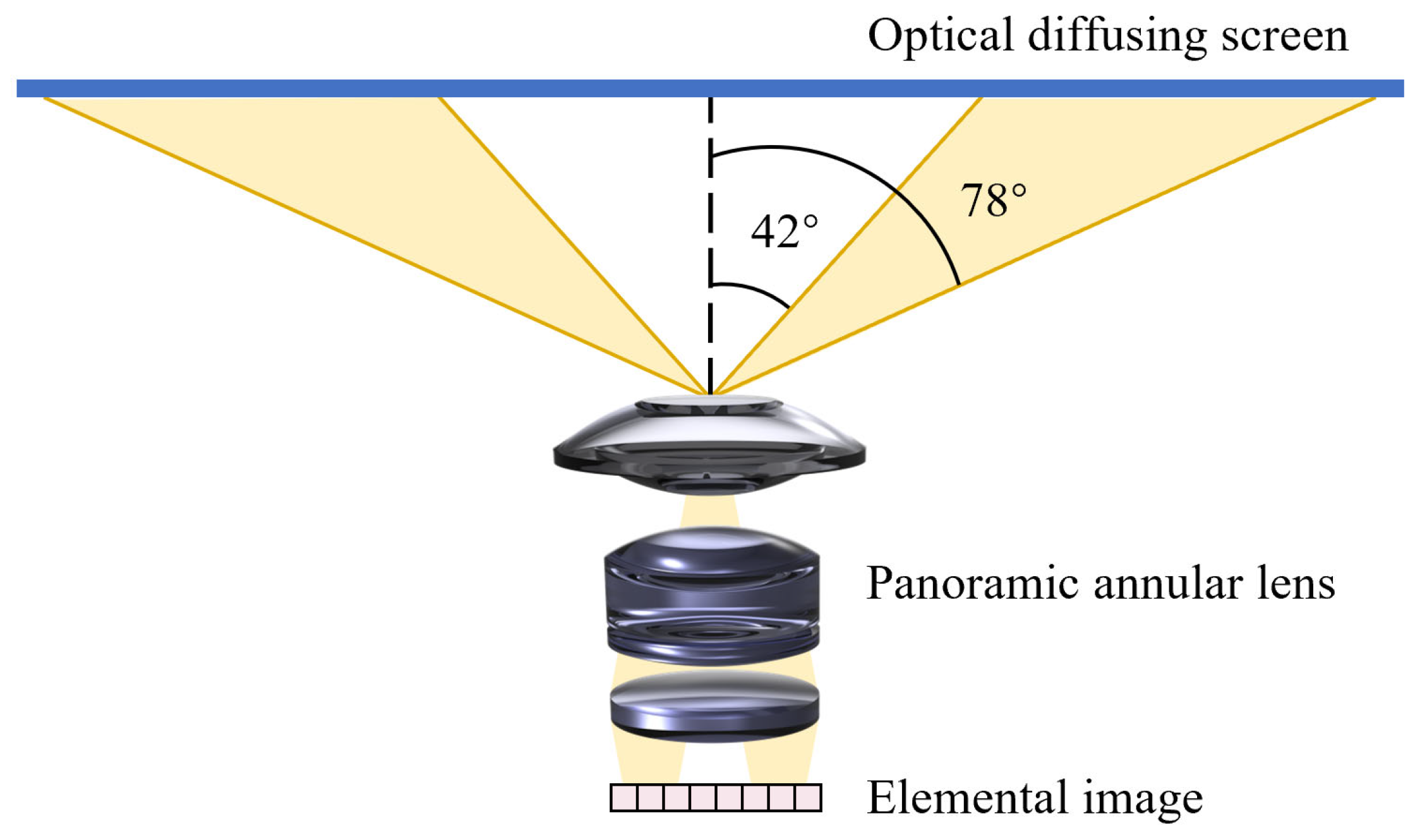
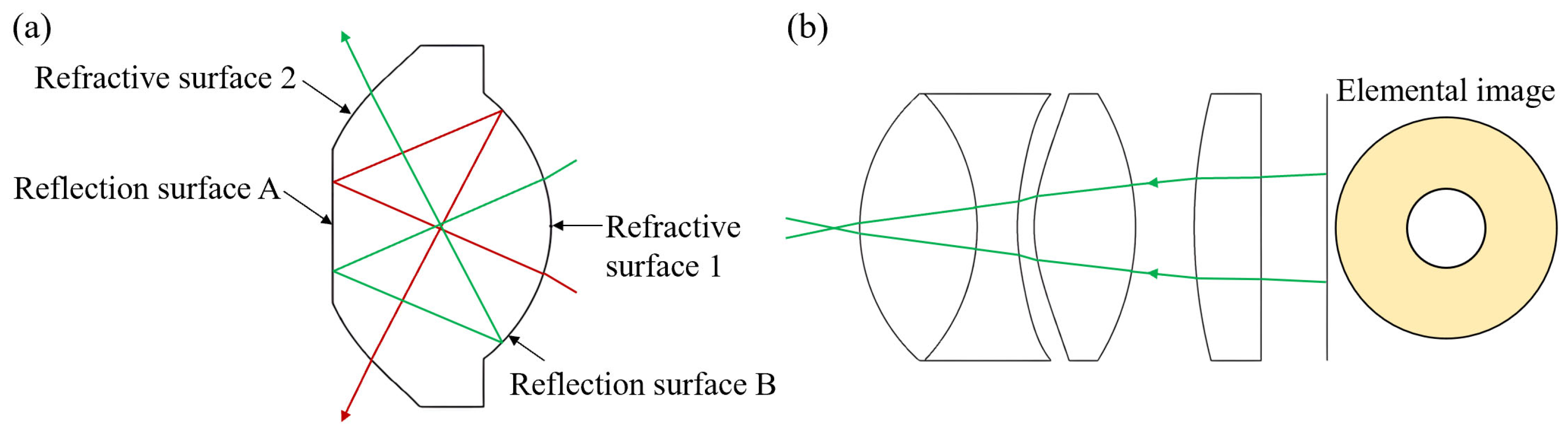
2.2. Design of Panoramic Annular Lens Array

The lens array is a critical optical component in the light field 3D display. To accommodate the modulation requirement for a wide angle, the panoramic annular lens array is designed and optimized. Compared with conventional imaging lenses, the main advantage of the panoramic annular lens is that the field of view is a ring, which can realize 360° imaging [23,24,25]. The proposed panoramic annular lens belongs to a catadioptric panoramic imaging system, comprising a block-structured panoramic front unit and a relay lens system. The block-structured panoramic front unit is a catadioptric structure composed of two reflection surfaces of A and B and two refractive surfaces of 1 and 2, as shown in Figure 3a. Rays passing through the relay lens system enter the block-structured panoramic front unit at a tiny angle so that the off-axis aberration can be significantly corrected. The rays are first refracted through the refractive surface 1, then reflected successively by the reflection surfaces A and B. The light then leaves the block-structured panoramic front unit through the refractive surface 2 to a wide angle.
In terms of the relay lens system, it is required to form an intermediate image inside the panoramic annular lens array to enter the block at a tiny angle. In addition, the relay lens system also has the aberration correction function. To fulfill these tasks, the relay lens system usually has many lens elements, as shown in Figure 3b. We determine the initial optical parameters and optimize both the block-structured panoramic front unit and the relay lens system. First, the initial optical model of the block-structured panoramic front unit is constructed. The block is then optimized, and it is verified whether all chief rays pass through the center of the diaphragm. If not, the initial optical model of the block is adjusted and the optimization process is restarted. Next, the relay lens system is optimized by incorporating aspherical lenses to reduce the total number of lenses. Finally, the block-structured panoramic front unit and relay lens system are simultaneously optimized to ensure that the complete panoramic annular lens achieves good image quality.
Figure 4 shows the layout of the optimized panoramic annular lens. The focal length is −2.887 mm and the annular field of view is 360° × (42–78°). The diameter of the block-structured panoramic front unit is 7.5 mm, which is larger than that of the relay lens system of 5.3 mm. Only one refractive surface in the relay lens system is spherical, with the radius of curvature of −10.067 mm, and all other reflection and refractive surfaces are optimized to be aspherical with different coefficients and high orders, as shown in Table 1. The damped least-squares method is utilized during the optimization of the aspherical surface. The spot diagram of the panoramic annular lens is shown in Figure 5. All spots have an rms radius in a range from 22.098 µm up to 24.937 µm, which is less than 30 µm, that is the sub-pixel size of the 2D display panel, ensuring that all the spots are small and compact. Therefore, the 3D image has a good reconstruction quality in the whole field of view. However, the large pitch of the panoramic annular lens engenders fundamental limitations in the depth-of-field performance of 3D images.

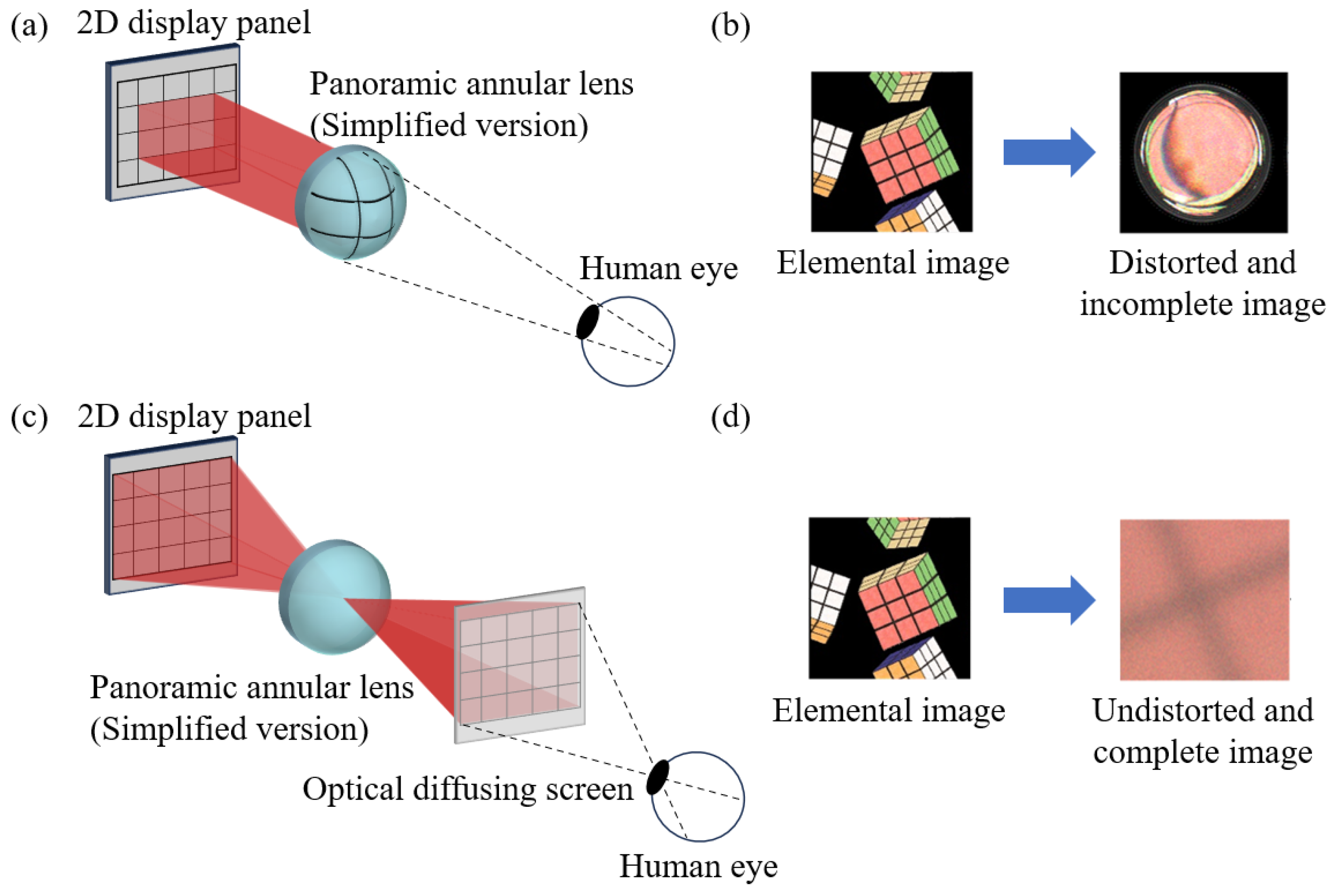
2.3. Characteristics of Optical Diffusing Screen

The main characteristic of the optical diffusing screen in the 3D display is ensuring that the 3D image passed through it is continuous, as mentioned in previous studies [19]. In addition to addressing the discontinuity issue, the optical diffusing screen also works for correcting the image distortion and incompleteness caused by each panoramic annular lens. If the optical diffusing screen is not utilized, the human eye would perceive a distorted and incomplete image when viewing the panoramic annular lens directly, as shown in Figure 6a,b. Note that the panoramic annular lens is simplified as a single lens in Figure 6 since all types of lenses with curvature have the same problem. The reason for distortion is that the outermost surface of the panoramic annular lens is curved; the rays emitted from different angles have different transverse magnifications when they pass through the lenses, and the magnified image on the lens surface is distorted. When this distorted image is imaged on the retina, the perceived image exhibits distortion in both horizontal and vertical directions compared with the original elemental image. In addition, the reason why the 3D image is incomplete is that the incident pupil is located at the panoramic annular lens array, and part of the rays emitted from the off-axis pixels of the elemental images cannot enter the human eye.
The distortion and incompletion of the 3D image can be eliminated by utilizing the optical diffusing screen. In Figure 6c, since the optical diffusing screen is planar, an undistorted planar image is formed around the optical diffusing screen after the rays emitted from the elemental images are modulated by the panoramic annular lens. The incident pupil is now located at the pupil of the human eye, and the diffused rays can then fully enter the human eye and are imaged on the retina when the optical diffusing screen is located at an appropriate distance. Therefore, the 3D image around the optical diffusing screen is undistorted and complete, as shown in Figure 6d. Previous studies have demonstrated that the diffusion angle θ of the optical diffusing screen is expressed as [26,27]
θ = arctan D l arctan p l
where D is the size of the elemental image or the pitch of the panoramic annular lens array, l is the distance between the optical diffusing screen and the panoramic annular lens, and p is the aperture of the panoramic annular lens. Since l is much greater than D and p, the diffusion angle θ is small.
Although a continuous 3D image without distortion and incompleteness is realized by using the optical diffusing screen, the size of the diffused spot increases due to the larger angle of incidence required to meet the viewing characteristics of the tabletop display. The diffusion from a large angle of incidence is shown in Figure 7. When the angle of incidence of φ is greater than the diffusion angle θ, the diffusion exhibits at the same side as the incident light, and the diffused spot size of S is expressed as
S = d [ tan ( θ + φ ) + tan ( θ φ ) ] ,
where d is the thickness of the diffusion layer in the optical diffusing screen. Apparently, the spot size gradually increases as the angle of incidence of φ increases, even with the same diffusion angle of θ. These formed spots eventually converge into multiple 3D image points, which are either the same size or slightly larger than the formed spots. Consequently, the resolution of the 3D images observed at wide viewing angles in the radial direction is degraded.

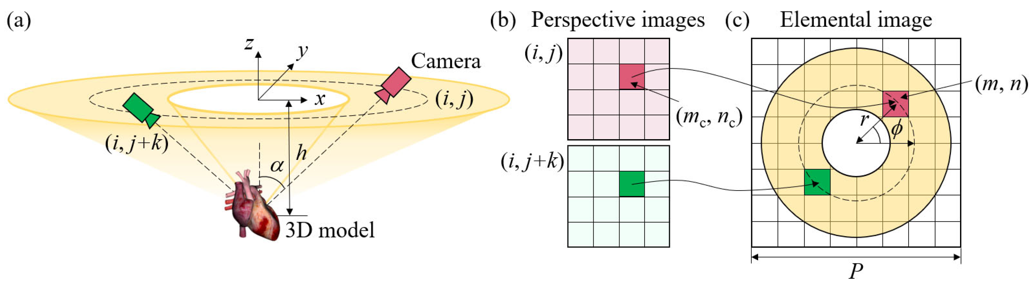
2.4. Generation of the Elemental Image Array

In the proposed tabletop 3D display, the elemental image array presented on the 2D display panel should precisely meet the modulation characteristic of the panoramic annular lens array, which is different from the conventional elemental image array. In the generation of the elemental image array, we first set up off-axis perspective cameras in multiple rings to capture the 3D model, where each camera corresponds to a viewpoint. All cameras are located at the same height h from the 3D model, and the camera indices in the circumferential and radial directions are denoted as i and j, respectively. A camera coordinate system is built according to the rings with different radii and the angle gap ωi between adjacent cameras in one ring. The coordinates (x, y, z)i,j of the (i, j)th camera are expressed as
x = h sin α max cos ω i j α α min α max α min y = h sin α max sin ω i j α α min α max α min z = h ,
where α represents the tilted angle of the (i, j)th camera in the radial direction, and αmin and αmax are equal to 42° and 78°, respectively. All cameras converge to a fixed point in the 3D model and capture multiple perspective images. The effective pixels of all perspective images are then mapped to the corresponding pixels of the elemental image array based on the geometric relationship between the viewpoint and the pixels on the 2D display panel. The pixel mapping relationship between the (i, j)th and (i, j + k)th perspective images and a single elemental image is shown in Figure 8. Note that the arrangement of the effective pixels in each elemental image is the same as that of the viewpoints as well as the cameras. The pixel mapping relationship between the elemental image array of E(m, n) and the perspective image of Ii,j(mc, nc) is calculated as
E m , n = I i , j m c , n c ,
m c = m / M ratio n c = n / N ratio ,
i = 2 r R / P j = ϕ / ω i ,
r = m m / P P P / 2 2 + n n / P P P / 2 2 ϕ = arctan n n / P P P / 2 / m m / P P P / 2 ,
where Mratio and Nratio are the resolution ratios of the elemental image array and the perspective images in the horizontal and vertical directions, respectively. r and ϕ represent the corresponding radius and angular coordinates of the pixel in a single elemental image, respectively. R is the number of the perspective images as well as the cameras in the circumferential direction. P is the number of pixels in each elemental image in both horizontal and vertical directions. In this case, all elemental images have a square shape, but the arrangement of the effective pixels, mapped from perspective images, follows the ring shape of the cameras or viewpoints, with no pixels at the center. The multiple viewpoint rendering algorithm based on rasterization rendering is utilized to generate the elemental image array, and the GPU parallel computing is used to accelerate the rendering process.

3. Results and Discussion

A simulation experiment is performed by developing a 1:1 3D model of the proposed tabletop 3D display with corresponding parameters and materials, to validate the feasibility of the 360° viewing effect and the advantage of a large radial viewing angle. In the simulated 3D model, the panoramic annular lens array is aligned with the 8K LCD display to ensure the compactness of the whole display system. The optical diffusing screen is placed at 30 mm above the panoramic annular lens array. Other detailed parameters are listed in Table 2.
In the experiment, an elemental image array of 7680 × 4320 pixels is generated using a 3D scene composed of four 3D models of one teapot, two spheres, and one circular ring. The elemental image array is pixel-mapped from 14,580 perspective images with the same resolution of 640 × 360 pixels. These perspective images are captured from cameras arranged on 30 rings and each with a different number of cameras. Figure 9 shows the elemental image array and the zoomed-in image, where the effective pixels of each elemental image have a ring-shaped structure. There are no effective pixels in the center region of each elemental image, meaning that the center pixels are wasted. However, the efficiency of the pixels still reaches more than 50%. The inner pixels in the elemental images correspond to the inner light rays with the radial angle of 42°, and the outer pixels correspond to the outer light rays with the radial angle of 78°.
Figure 10 shows the rendered 3D images captured from different positions along with a complete circular trajectory. Clearly, different perspectives within 360° can be seen from different geometric relationships between the four 3D models. In addition, the 3D images captured from different positions of −78.4°, −60.6°, −42.2°, 42.6°, 60.1°, and 78.9°, along with the radial direction, are shown in Figure 11, which verifies the correct perspective and parallax in the radial direction. Viewers or cameras located at all positions can see the 3D images, and the viewing zone in the radial direction ranges from −78.4° to −42.2° and 42.6° to 78.9°, meaning that the whole radial viewing angle is 72.5°. However, the brightness is decreased as the radial viewing position increases due to the severe light diffusion in a large angle of incidence and the image distortion observed from larger radial viewing positions.
The above-mentioned 3D images captured in circumferential and radial directions show that the proposed 3D display based on a panoramic annular lens array is suitable for the tabletop display form. However, the resolution of the 3D images is limited due to the large diffusion characteristic from a large angle of incidence and the large aperture of the panoramic annular lens. It confirms that the 3D image resolution will be improved when the aperture of the panoramic annular lens is decreased and the optical diffusing screen is optimized with a small diffusion angle at a large angle of incidence. Furthermore, the depth of field is limited due to the large pitch of the panoramic annular lens, which causes the parallax to be not particularly obvious. In the future, we will focus on optimizing the panoramic annular lens array to further improve its field of view and decrease its aperture while maintaining good imaging quality. In addition, an optical diffusing screen with a gradient diffusion angle in both horizontal and vertical directions will be utilized to resolve the severe diffusion problem in the large angle of incidence.

4. Conclusions

In summary, we propose a tabletop 3D display with a large radial viewing angle, which consists of a 2D display panel, a panoramic annular lens array, and an optical diffusing screen. The panoramic annular lens array plays a crucial role in improving the radial viewing angle and achieving an ideal ring-shaped viewing zone. The results of the simulation experiments indicate that the proposed tabletop 3D display has a radial viewing angle of 72.5°, ranging from −78.4° to −42.2° and 42.6° to 78.9°, and provides a 360° viewable 3D image with correct perspective and parallax. In the future, this new type of lens is expected to be further optimized and miniaturized, potentially serving as an alternative to current tabletop 3D displays.

Author Contributions

Conceptualization, M.-Y.H. and Y.X.; methodology, M.-Y.H., X.-R.W. and Y.-J.L.; software, M.-Y.H.; validation, M.-Y.H., C.-B.Z. and X.-R.W.; formal analysis, Q.-H.W. and Y.X.; investigation, C.-B.Z.; resources, Y.X. and Q.-H.W.; writing—original draft preparation, Y.X., M.-Y.H., C.-B.Z., X.-R.W. and Y.-J.L.; writing—review and editing, Y.X. and Q.-H.W.; visualization, Y.X. and C.-B.Z.; supervision, Y.X. and Q.-H.W.; funding acquisition, Y.X. and Q.-H.W. All authors have read and agreed to the published version of the manuscript.

Funding

This work was supported by the National Key R&D Program of China (Grant No. 2023YFB2806800) and the National Natural Science Foundation of China (Grant Nos. 62375009, 62335002).

Institutional Review Board Statement

Not applicable.

Informed Consent Statement

Not applicable.

Data Availability Statement

Dataset available on request from the authors.

Acknowledgments

We would like to extend our sincere appreciation to Lin-Bo Zhang from Beihang University for his invaluable advice on the experimental aspects of tabletop 3D display.

Conflicts of Interest

The authors declare no conflicts of interest.

References

  1. Jones, A.; McDowall, I.; Yamada, H.; Bolas, M.; Debevec, P. Rendering for an interactive 360° light field display. ACM Trans. Graph. 2007, 20, 40-es. [Google Scholar] [CrossRef]
  2. Otsuka, R.; Hoshino, T.; Horry, Y. Transpost: 360 deg-viewable three-dimensional display system. Proc. IEEE 2006, 94, 629–635. [Google Scholar] [CrossRef]
  3. Yoshida, S. fVisiOn: 360-degree viewable glasses-free tabletop 3D display composed of conical screen and modular projector arrays. Opt. Express 2016, 24, 13194–13203. [Google Scholar] [CrossRef]
  4. Xia, X.; Liu, X.; Li, H.; Zheng, Z.; Wang, H.; Peng, Y.; Shen, W. A 360-degree floating 3D display based on light field regeneration. Opt. Express 2013, 21, 11237–11247. [Google Scholar] [CrossRef]
  5. Chen, X.; Chen, L.; Qiao, W. 56-2: Tabletop 3D display with triple viewing zones. SID Symp. Dig. Tech. Pap. 2019, 50, 779–782. [Google Scholar] [CrossRef]
  6. Yu, X.; Dong, H.; Gao, X.; Fu, B.; Pei, X.; Zhao, S.; Yan, B.; Sang, X. 360-degree directional micro prism array for tabletop flat-panel light field displays. Opt. Express 2023, 31, 32273–32286. [Google Scholar] [CrossRef]
  7. Takaki, Y.; Uchida, S. Table screen 360-degree three-dimensional display using a small array of high-speed projectors. Opt. Express 2012, 20, 8848–8861. [Google Scholar] [CrossRef]
  8. Makiguchi, M.; Sakamoto, D.; Takada, H.; Honda, K.; Ono, T. Interactive 360-degree glasses-free tabletop 3D display. In Proceedings of the 32nd Annual ACM Symposium on User Interface Software and Technology, Sapporo, Japan, 20–23 October 2019. [Google Scholar]
  9. Takaki, Y.; Nakamura, J. Generation of 360-degree color three-dimensional images using a small array of high-speed projectors to provide multiple vertical viewpoints. Opt. Express 2014, 22, 8779–8789. [Google Scholar] [CrossRef]
  10. Yan, X.P.; Yan, Z.; Jing, T.; Zhang, P.; Lin, M.; Li, P.; Jiang, X.Y. Enhancement of effective viewable information in integral imaging display systems with holographic diffuser: Quantitative characterization, analysis, and validation. Opt. Laser Technol. 2023, 161, 109101. [Google Scholar] [CrossRef]
  11. Bai, Y.C.; Deng, H.; Yang, C.N.; Chen, Y.A.; Zhao, C.J.; Tang, J. Sub-pixel marking and depth-based correction methods for the elimination of voxel drifting in integral imaging display. Opt. Express 2024, 32, 12243–12256. [Google Scholar] [CrossRef]
  12. Zhao, C.J.; Guo, Z.D.; Deng, H.; Yang, C.N.; Bai, Y.C. Integral imaging three-dimensional display system with anisotropic backlight for the elimination of voxel aliasing and separation. Opt. Express 2023, 31, 29132–29144. [Google Scholar] [CrossRef] [PubMed]
  13. Yeom, J.; Son, Y.; Choi, K. Crosstalk reduction in voxels for a see-through holographic waveguide by using integral imaging with compensated elemental images. Photonics 2021, 8, 217. [Google Scholar] [CrossRef]
  14. Zheng, Y.W.; Chu, F.; Lin, F.C.; Hu, Y.X.; Li, Y.L.; Zheng, Y.; Wang, D.; Wang, Q.H. Wide-viewing-angle color holographic 3D display system with high brightness encoding. PhotoniX 2025, 6, 3. [Google Scholar] [CrossRef]
  15. Hua, J.; Qiao, W.; Chen, L. Recent advances in planar optics based glasses-free 3D displays. Front. Nanotechnol. 2022, 4, 829011. [Google Scholar] [CrossRef]
  16. Hua, J.; Hua, E.; Zhou, F.; Shi, J.; Wang, C.; Duan, H.; Hu, Y.Q.; Qiao, W.; Chen, L. Foveated glasses-free 3D display with ultrawide field of view via a large-scale 2D-metagrating complex. Light Sci. Appl. 2021, 10, 213. [Google Scholar] [CrossRef]
  17. Liu, Y.; Wang, G.; Feng, F.; Zhanghu, M.Y.; Yuan, Z.N.; Li, Z.H.; Xu, K.; Kwok, H.S.; Liu, Z.J. Ultra-low-defect homoepitaxial micro-LEDs with enhanced efficiency and monochromaticity for high-PPI AR/MR displays. PhotoniX 2024, 5, 23. [Google Scholar] [CrossRef]
  18. Gao, X.; Sang, X.; Yu, X.; Zhang, W.; Yan, B.; Yu, C. 360 light field 3D display system based on a triplet lenses array and holographic functional screen. Chin. Opt. Lett. 2017, 15, 121201. [Google Scholar]
  19. Xing, Y.; Lin, X.Y.; Zhang, L.B.; Xia, Y.P.; Zhang, H.L.; Cui, H.Y.; Li, S.; Wang, T.Y.; Ren, H.; Wang, D.; et al. Integral imaging-based tabletop light field 3D display with large viewing angle. Opto-Electron. Adv. 2023, 6, 220178-1–220178-12. [Google Scholar] [CrossRef]
  20. Yu, X.; Sang, X.; Gao, X.; Yan, B.; Chen, D.; Liu, B.; Liu, L.; Gao, C.; Wang, P. 360-degree tabletop 3D light-field display with ring-shaped viewing range based on aspheric conical lens array. Opt. Express 2019, 27, 26738–26748. [Google Scholar] [CrossRef]
  21. Xing, Y.; Xia, Y.P.; Li, S.; Ren, H.; Wang, Q.H. Annular sector elemental image array generation method for tabletop integral imaging 3D display with smooth motion parallax. Opt. Express 2020, 28, 34706–34716. [Google Scholar] [CrossRef]
  22. Xia, Y.P.; Li, S.; Ren, H.; Deng, H.; Xing, Y. High-efficient rendering to generate annular sector elemental image array for tabletop integral imaging three-dimensional display. J. Soc. Inf. Disp. 2021, 29, 632–641. [Google Scholar] [CrossRef]
  23. Zhou, X.; Bai, J.; Wang, C.; Hou, X.; Wang, K. Comparison of two panoramic front unit arrangements in design of a super wide angle panoramic annular lens. Appl. Opt. 2016, 55, 3219–3225. [Google Scholar] [CrossRef] [PubMed]
  24. Wang, X.; Zhong, X.; Zhu, R.; Gao, F.; Li, Z. Extremely wide-angle lens with transmissive and catadioptric integration. Appl. Opt. 2019, 58, 4381–4389. [Google Scholar] [CrossRef] [PubMed]
  25. Zhang, K.; Zhong, X.; Zhang, L.; Zhang, T. Design of a panoramic annular lens with ultrawide angle and small blind area. Appl. Opt. 2020, 59, 5737–5744. [Google Scholar] [CrossRef]
  26. Liu, Y.J.; Wen, X.R.; Li, W.Z.; Xing, Y.; Zhang, H.L.; Wang, Q.H. P-123: Analysis of light shaping diffuser in integral imaging based light field display. SID Symp. Digest Tech. Papers 2014, 55, 1866–1869. [Google Scholar] [CrossRef]
  27. Yan, Z.; Yan, X.; Huang, Y.; Jiang, X.; Yan, Z.; Liu, Y.; Mao, Y.; Li, P. Characteristics of the holographic diffuser in integral imaging display systems: A quantitative beam analysis approach. Opt. Lasers Eng. 2021, 139, 106484. [Google Scholar] [CrossRef]
Figure 1. Schematic diagram of (a) the configuration of the proposed tabletop 3D display and (b) the ray path to reconstruct 3D image with a large radial viewing angle.
Photonics 12 00515 g001
Figure 2. Modulation of the panoramic annular lens to achieve a large radial angle.
Photonics 12 00515 g002
Figure 3. Schematic diagram of (a) the block-structured panoramic front unit and (b) the relay lens system.
Photonics 12 00515 g003
Figure 4. Layout of the optimized panoramic annular lens. Blue and purple rays represent the optical path with the incident angles of 42° and 78°, respectively.
Photonics 12 00515 g004
Figure 5. Spot diagram of the optimized panoramic annular lens.
Photonics 12 00515 g005
Figure 6. Comparison of the perceived images with and without the optical diffusing screen. (a) Schematic diagrams of the image perception process by the human eye when the optical diffusing screen is not utilized, and (b) the perceived distorted and incomplete image. (c) Schematic diagrams of the image perception process when the optical diffusing screen is utilized, and (d) the perceived undistorted and complete image.
Photonics 12 00515 g006
Figure 7. Diffusion model for a large angle of incidence.
Photonics 12 00515 g007
Figure 8. Pixel mapping relationship between the (a) cameras, (b) perspective images captured by the corresponding cameras, and (c) elemental image. (i, j) and (i, j + k) represent the indices of two different cameras in one ring or the corresponding captured perspective images. (mc, nc) and (m, n) represent the pixel indices of each perspective image and the elemental image array, respectively.
Photonics 12 00515 g008
Figure 9. Corresponding elemental image array. The 3D scene consists of one teapot, two spheres, and one circular ring.
Photonics 12 00515 g009
Figure 10. Three-dimensional images captured from different positions along the circumferential direction. The circumferential perspective and parallax are correct.
Photonics 12 00515 g010
Figure 11. Three-dimensional images captured from different positions of −78.4°, −60.6°, −42.2°, 42.6°, 60.1°, and 78.9° along the radial direction.
Photonics 12 00515 g011
Table 1. Parameters of the panoramic annular lens unit.
ParametersValues
S1Conic6.266
Index of refraction1.497
4th order term−5.697 × 10⁻⁴
6th order term2.079 × 10−5
8th order term−2.73 × 10⁻⁷
S2Conic−5.666
4th order term4.752 × 10−4
6th order term−2.171 × 10⁻⁶
8th order term8.093 × 10−8
S3Conic7.099
Index of refraction1.497
2nd order term−1.802
4th order term1.537 × 10−4
S4Conic−7.733
Index of refraction1.626
2nd order term6.132
4th order term4.752 × 10−4
S5Conic8.833
4th order term1.210 × 10−4
6th order term3.174 × 10−6
8th order term4.578 × 10−7
S6Conic5.799
Index of refraction1.497
4th order term1.701 × 10−5
6th order term−3.447 × 10⁻⁶
8th order term2.064 × 10−8
S7Conic−10.066
S8Conic21.199
Index of refraction1.626
6th order term2.170 × 10−6
8th order term1.093 × 10−8
Table 2. Parameters of the simulated tabletop 3D display.
ParametersValues
2D display panelPixel size0.09 mm
Dimension698.11(W)mm × 392.69(H)mm
Resolution7680 × 4320 pixels
Elemental image arrayNumber of elemental images64 × 36
Size of elemental image (D)7.8 mm × 7.8 mm
Panoramic annular
lens array
Pitch7.8 mm × 7.8 mm
Thickness27.8 mm
Number of lenses64 × 36
Lens layoutRectangle
Optical diffusing screenDiffusion angle (θ)10°
Thickness of the diffusion layer (d)0.25 mm
PC for generation of the
elemental image array
CPUIntel(R) Core™
i9-13900K
Main memory64 GB
GPUNVIDIA RTX GeForce 4090 Laptop
Main memory16 GB
Disclaimer/Publisher’s Note: The statements, opinions and data contained in all publications are solely those of the individual author(s) and contributor(s) and not of MDPI and/or the editor(s). MDPI and/or the editor(s) disclaim responsibility for any injury to people or property resulting from any ideas, methods, instructions or products referred to in the content.

