Article

A Hermetic Package Technique for Multi-Functional Fiber Sensors through Pressure Boundary of Energy Systems Based on Glass Sealants

1
Department of Electrical and Computer Engineering, University of Pittsburgh, Pittsburgh, PA 15261, USA
2
School of Ocean Information Engineering, Jimei University, Xiamen 361021, China
3
Institute of Nuclear and New Energy Technology, Key Laboratory of Advanced Reactor Engineering and Safety of Ministry of Education, Collaborative Innovation Center for Advanced Nuclear Energy Technology, Tsinghua University, Beijing 100084, China
4
Department of Petroleum Engineering, Louisiana State University, Baton Rouge, LA 70803, USA
*
Author to whom correspondence should be addressed.
These authors contributed equally to this work.
Photonics 2024, 11(9), 792; https://doi.org/10.3390/photonics11090792
Submission received: 26 June 2024 / Revised: 22 August 2024 / Accepted: 23 August 2024 / Published: 25 August 2024
(This article belongs to the Special Issue Quantum Enhanced Devices and Instruments for Sensing Applications)

Abstract

:
This paper presents a hermitic fiber sensor packaging technique that enables fiber sensors to be embedded in energy systems for performing multi-parameter measurements in high-temperature and strong radiation environments. A high-temperature stable Intrinsic Fabry–Perot interferometer (IFPI) array, inscribed by a femtosecond laser direct writing scheme, is used to measure both temperature and pressure induced strain changes. To address the large disparity in thermo-expansion coefficients (TECs) between silica fibers and metal parts, glass sealants with TEC between silica optical fibers and metals were used to hermetically seal optical fiber sensors inside stainless steel metal tubes. The hermetically sealed package is validated for helium leakages between 1 MPa and 10 MPa using a helium leak detector. An IFPI sensor embedded in glass sealant was used to measure pressure. The paper demonstrates an effective technique to deploy fiber sensors to perform multi-parameter measurements in a wide range of energy systems that utilize high temperatures and strong radiation environments to achieve efficient energy production.

1. Introduction

Optical fiber sensors today are widely applied in harsh situations (aerospace industry, nuclear power plants, and so on) due to their resistance to the environment, remote sensing, and simultaneous monitoring of different parameters (temperature, strain, humidity, etc.) [1,2,3,4,5,6,7]. As point fiber sensors, the Fabry–Perot interferometer (FPI) has special advantages such as easier fabrication, higher measuring sensitivity, and a more accurate measuring region compared with the fiber Bragg grating sensor (FBG) [8,9,10]. The FPI can be divided into two types based on its relative positions with fiber: the extrinsic FabryPerot interferometer (EFPI) and the intrinsic FabryPerot interferometer (IFPI). In contrast to EFPI, IFPI possessed lower insertion loss and an easier installation or package method, which determined that IFPI was more stable and suitable for structural health monitoring. The IFPI inside a single-mode optical fiber inscribed by a femtosecond laser was proven to achieve multiple monitoring (high temperature up to 1000 °C, gas, vibration, etc.) under harsh environments by much research [11,12,13,14,15].
Normally, the coating material near the FP cavity on a mode fiber should be removed to achieve a more stable and reliable measuring signal of IFPI, especially under harsh environments like nuclear power plants; however, this would greatly decrease the mechanical strength of optical fiber when attached to or embedded in the measured structure or object, which could lead to signal interference or even the breaking down of IFPI. Therefore, the fiber package technique was applied to IFPI to perform the monitoring successfully in harsh environments in this paper.
Polymer and metal are the two main common package materials for fiber sensors [16,17]. Most polymer-based fiber packages are convenient to fabricate and can bear limited environmental loads [18,19,20,21]. Metal packages (aluminum, nickel, and so on) can protect optical fiber in two ways. The capillary metal tube keeps fiber sensors in minimal space without direct fuse with fiber in civil structures [22,23], but the strain sensitivity of the sensors would be decreased, and it is not suitable for contact measurements like vibration or gas monitoring in harsh environments. The electroplated metal would not affect the sensitivity, but the huge difference (larger than 20 times) in the coefficient of thermal expansion (CTE) between fiber (5.5 × 10⁻⁷) and metal (>2 × 10⁻⁵) can damage the fiber sensors extremely [24,25]. Both of these package methods were not perfect for the sensitive and fragile IFPI applied in harsh environments. Based on previous research on glass-to-metal sealing structure measuring via FBG sensors, glass was proposed to be the novel package material for IFPI in this paper. This concept was first proposed in the 1990s [26], in which the solder glass was proposed to shelter the fiber to resist corrosion, but real-time monitoring of parameters was not achieved at that time.
Glass sealant material was mainly used for hermetic boundaries under harsh conditions (high temperature up to 1000 °C, high pressure up to 10 MPa, and radiation environments) [27]. The glass sealant was proven to achieve seamless fusion with optical fiber sensors, which would not affect the hermeticity of the glass sealant or measure the sensitivity of fiber sensors [28,29,30]. The glass sealant was also capable of being the proper transition layer between fiber and capillary metal tube with a CTE of around 10 × 10−6. At the same time, the glass fixed the position of the fiber in a metal tube so the strain and vibration loads could be transmitted effectively to fiber sensors. Additionally, fiber is known to be insensitive to the pressure load, and the sealant structure can convert the environmental pressure to the strain change in the glass layer, so the embedded IFPI can monitor the pressure simultaneously [31]. As a result, the IFPI would have the potential to monitor multiple parameters (temperature, strain, pressure, etc.) in nuclear power plants with the protection of a glass package.
In this research, the glass package of IFPI was manufactured through the heating process first. During this time, the temperature sensitivity of IFPI was calibrated by a standard thermal couple near the experimental model in the furnace. After the cooling process, the precise small-scale strain imposed by the contraction of the glass package was measured. The leakage rate of the glass sealant package was determined by the helium leak detector at high temperatures and pressures. Then, the experimental model was installed in a high-pressure pipeline to monitor the environmental pressure loads reflected by the strain change in IFPI. Based on the monitored results, this packaging technique may have the potential for simultaneous multiple-parameter monitoring in nuclear power plants based on the IFPI array in the future.

2. Experimental Design and Setup

2.1. IFPI Demodulation Method

The interference spectrum of an IFPI is expressed in Equation (1), assuming an identical reflection strength from two reflectors [32,33,34]:
I k = 2 I 0 k 1 + γ c o s 2 k l OPD + φ 0
where k = 2 π / λ is the wavevector, I 0 k is the reflection spectrum of incident light at the reflector, γ is the fringe visibility of interference signals, l OPD   is the optical path length of the IFPI cavity, and φ 0 is the phase delay of light transmitting from the first reflector. The φ 0 is set to zero because the length of the nanograting reflector (3 μm) is much smaller than the cavity length (250~2000 μm).
The l OPD will increase when imposed with thermal loads, as shown in Equation (2) [31]:
Δ l OPD = l OPD ζ + α Δ T + ε
where ζ is the thermo-optic coefficient of 8.6 × 10⁻⁶/°C for Ge-doped silica-core fiber, α is the thermal expansion coefficient, with a value of 5.5 × 10⁻⁷/°C. A Fast Fourier Transform (FFT) algorithm was applied to demodulate the absolute F-P cavity length based on Buneman frequency estimation and simple phase calculation on the interference spectrums. Therefore, the real-time F-P cavity length would be obtained, and the related temperature or strain change could be demodulated.
The detailed fabrication process is shown in Figure 1a. A Coherent RegA 9000 Ti:sapphire laser and amplifier system were applied for fabrication. A linearly polarized laser beam of 800 nm, 270 fs, and 250 kHz repetition rate was produced and focused inside the fiber core through a 100× oil-immersion objective (Olympus 1-U2B235, N.A. 1.25). The laser focus was aligned with the middle of the fiber core to produce artificial scattering centers. Six Rayleigh-enhanced points were inscribed in the fiber core to form three IFPIs. The gap between adjacent IFPI was 5 mm, and the cavity length increased incrementally from 985 µm to 1.6 mm with a step of 350 µm.
During the fabrication and pressure experiments, a 60 nm bandwidth broadband light ranging between 1510 nm and 1570 nm from a Super-luminescent Light Emitting Diode (SLED, EXS210059-01) was coupled to an IFPI array embedded in a glass package via a circulator. The interference fringes were detected by the 512-pixel CCD-based spectrometer (Bayspec, FBGA) with a spectral range from 1510 nm to 1590 nm. The location and reflection strength of the nanograting reflectors were characterized by the optical backscatter reflectometer (OBR 4600, LUNA) measured backscattering profile in Figure 1c. The interference fringe and FFT transformation of the multiplexed sensors are shown in Figure 1d,e.

2.2. Package Fabrication

The sealing glass applied in this research was the GL1732P sealing glass with a particle size below 45 microns, provided by Mo·Sci. The composition is shown in Table 1. The glass powder will initially be mixed with wax, serving as an organic binder, at a mass ratio of 16:1. The sample will then be heated to 120 °C to fully melt the wax and integrate it with the glass powder. After cooling, the sample will be ground into small particles. Subsequently, the glass powder and wax mixture will be pressed into a cylinder with a channel using a customized mold designed to accommodate the embedded optical fiber. A dewaxing process will then be performed by heating the sample to 250 °C for one hour, decomposing the wax into gases and vapors.
Based on the softening point Td around 370 °C, the sealing process was designed as ramping to 450 °C, holding for 30 min, and then cooling to room temperature with a rate of around 10 °C/min. When the glass sealant is heated beyond its softening point, it becomes very soft or semi-liquid, spreading out to fully contact the fiber and the stainless-steel tube, forming a strong seal upon cooling. After 30 min of heating, the cooling process begins, and the sealant transitions back to a solid, rigid state, bonding to both the fiber and the shielding.
The glass sealant, metal tube, and fiber will be fixed, as illustrated in Figure 1b. The entire experimental model will then be placed in a heating furnace to undergo the sealing process, as depicted in Figure 2a. Meanwhile, a standard thermocouple was placed in the same region of the furnace to calibrate the temperature sensing parameter of the IFPI. After the sealing process, the glass package will be successfully fabricated onto the IFPI on the fiber. A metal shield was installed on the other end of the metal tube and welded to the tube with solder. The practicable IFPI sample with a glass package was obtained, as shown in Figure 1b.

2.3. Leakage Detection and Pressure Monitoring Experiment

After the package fabrication, the experimental model was taken out of the heating furnace. The leakage detection experiment was carried out on the glass sealant package by a helium leak detector, and then the hermeticity and reliability of this package would be demonstrated.
Due to their structure characteristics, most fiber sensors were insensitive to pressure loads. Research showed that special coatings could improve the pressure sensitivity of fiber sensors with limited effect. The IFPI glass-to-metal seal structure could convert the pressure loads to the strain change in IFPI due to the glass package contraction within the hermetic chamber formed by the metal tube, glass package, and pipeline. Based on that, the metal tube of the experimental model was installed to the high-pressure pipeline through ferrule, as shown in Figure 2b, to monitor the pressure from 1 MPa to 10 MPa.

3. Numerical Simulation

To prove the reliability of strain and pressure measuring results in the package fabrication and pressure experiments with a theoretical foundation, a finite element model of optical fiber with fused glass sealant and a metal tube was built. The finite element method was an efficient method to predict the strain distribution of glass-to-metal structures [35,36,37]. The linear elastic material model was used in this research, with temperatures ranging from 20 °C to 370 °C. Because the residual strain in optical fiber was generated only after the glass package began to cure, the simulation focused on the cooling process after the temperature reached Td for the glass sealant.
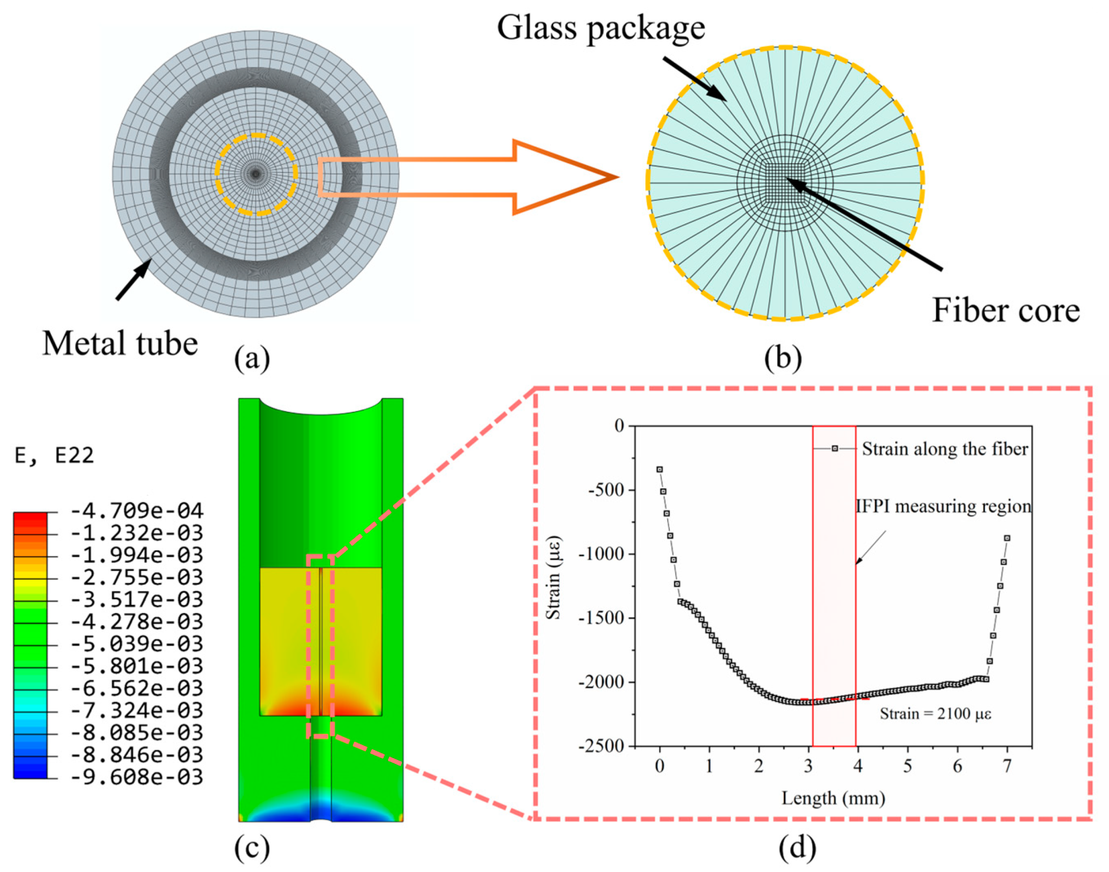
The pressure loads were imposed on the bottom end of the glass package to simulate the pressure experiments after the curing process. The strain distribution along the middle path of the fiber core was extracted, as shown in Figure 3c, which was also the measuring path in the experiments. Because the IFPI embedded in the glass package was less than 1 mm, the mean value of the strain on the F-P cavity was considered a theoretical comparison to the experimental results.

4. Results and Discussion

4.1. Fabrication Monitoring and Strain Measuring

The three IFPI started to monitor the whole fabrication process of the glass package after being embedded into the glass sealant, as shown in Figure 4a. The monitoring signal for all three IFPIs was steady. To describe and distinguish each measuring result, the IFPI sealed with a glass package was the strain sensor, and the other two IFPI beside the glass package were, respectively, temperature sensor 1 (cavity 1298.9 μm) and temperature sensor 2 (cavity 1611.5 μm).
The temperature sensing curves of both temperature sensors rise linearly from room temperature to 450 °C, hold for 30 min, and then cool down naturally to room temperature. The temperature measurement was calibrated according to the standard thermal couple installed, as shown in Figure 2a. Temperature sensor 1 and sensor 2 achieved accurate and consistent measurements during both the heating-up and cooling-down processes with a deviation of less than 0.001%. The temperature sensitivity of each (0.0137 for sensor 1 and 0.01672 for sensor 2) was close to the theoretical value (0.01298 and 0.01611, respectively), as proved by Equation (2). For the strain sensor, it also measured temperature precisely before fusing with the glass package, for which the sensitivity of 0.00943 was close to the theoretical value of 0.0905. As a result, the IFPI could achieve accurate and sensitive temperature measurements, which was a powerful method to adjust the fabrication process and improve the package quality.
The strain sensor started to sense the strain imposed by the glass package after the cooling temperature reached Td 370 °C. At the same time, the cavity length change was also affected by cooling down. Due to the fact that temperature and strain were independent, as stated by Equation (2), the cross-sensitivity could be demodulated based on the calibration result shown in Figure 4d because the temperature sensing was consistent during the heating-up and cooling-down processes. Thus, the cavity change (blue line) induced by strain could be obtained by subtracting the temperature-induced change (red line) from the whole change (black line).
The specific strain value increased to about 1675 με. The axial strain distribution was extracted from the cavity region (985 μm in the middle of the glass package) to make comparisons. The mean value of theoretical strain was 2100 με, and the deviation between the experimental and theoretical results was only 20%, which could prove the excellent performance of IFPI in measuring small-scale strain. In contrast to the measuring results of FBG, the IFPI could realize distinct monitoring without the effect of a chirped spectrum [29]. Therefore, the IFPI could be applied to the multi-point precise positions in the system/structure.

4.2. Leakage Detection and Pressure Monitoring

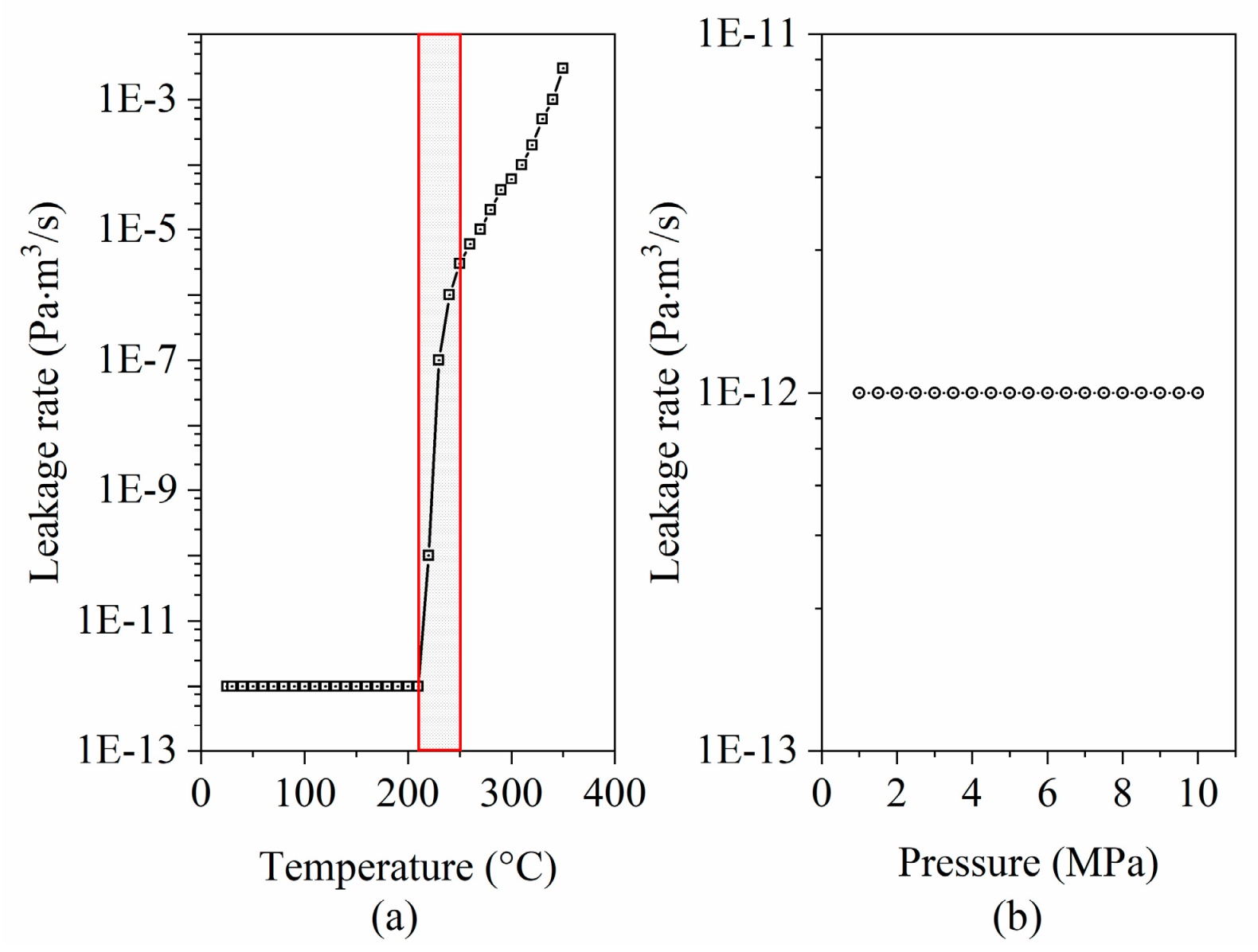
The leakage rate of the glass sealant package was detected under high temperature and high-pressure environments to prove the hermeticity of pressure boundaries. The metal shell of IFPI was welded to form a vacuum chamber. The chamber was, respectively, placed into the furnace and pipeline to experience the thermal and pressure loads. One side of the chamber was connected to the helium leak detector, and the other side was attached to a helium bag. The leakage rate would be determined under different temperatures and pressures, as shown in Figure 5.
The hermeticity of the glass sealant package was in good condition under 200 °C, and the leakage rate began to rise when the temperature reached 210 °C. The leakage rate could meet performance requirements (<1 × 10⁻⁷ Pa × m3/s) in nuclear power plants applied at a working temperature of 250 °C. Compared with the resistance to high temperatures, the glass sealant package had better endurance in high-pressure environments. There was no change in the leakage rate from 1 MPa to 10 MPa (<1 × 10⁻¹² Pa × m3/s), which proved the hermeticity of the glass sealant package could bear high-pressure working loads without destructive failure. As a result, the hermetic package was feasible to apply to pressure boundaries for energy systems.

5. Conclusions and Future Work

This research investigated a novel package technique used on IFPI to achieve multiple parameters under harsh environments based on glass sealant.
(1)
The temperature measuring results of IFPI were precise and consistent during the fabrication process, with a deviation of less than 0.001%, and the calibrated temperature sensitivity was almost the same as the theoretical value obtained from Equation (2).
(2)
The IFPI was able to measure the small-scale strain in the glass package during the curing process. The specific value of 1675 με was close to the numerical results of 1950 με obtained via finite element analysis (deviation less than 13%).
(3)
The hermeticity of the glass sealant package was demonstrated to be feasible at high temperatures (20~250 °C) and high pressure (1~10 MPa).

Author Contributions

Z.F. and S.Z. wrote the main manuscript text, and all authors K.Z., Q.W., Y.L., G.Z., G.M., J.Z., H.Y., Z.H., J.S. and K.P.C. reviewed the manuscript. All authors have read and agreed to the published version of the manuscript.

Funding

This research was funded by the Department of Energy (DE-NE0008994 and DE-NE0009153).

Institutional Review Board Statement

Not applicable.

Informed Consent Statement

Not applicable.

Data Availability Statement

Data is contained within the article.

Acknowledgments

The authors wanted to thank the reviewers for their valuable comments.

Conflicts of Interest

The authors declare no conflicts of interest.

References

  1. Kim, H.J.; Shin, H.Y.; Pyeon, C.H.; Kim, S.; Lee, B. Fiber-optic humidity sensor system for the monitoring and detection of coolant leakage in nuclear power plants. Nucl. Eng. Technol. 2020, 52, 1689–1696. [Google Scholar] [CrossRef]
  2. Berruti, G.M.; Vaiano, P.; Quero, G.; Das Neves, T.F.P.; Boniello, A.; Consales, M.; Petagna, P.; Cusano, A. Analysis of uncoated LPGs written in B-Ge doped fiber under proton irradiation for sensing applications at CERN. Sci. Rep. 2020, 10, 1344. [Google Scholar] [CrossRef] [PubMed]
  3. Goossens, S.; De Pauw, B.; Geernaert, T.; Salmanpour, M.S.; Khodaei, Z.S.; Karachalios, E.; Saenz-Castillo, D.; Thienpont, H.; Berghmans, F. Aerospace-grade surface mounted optical fiber strain sensor for structural health monitoring on composite structures evaluated against in-flight conditions. Smart Mater. Struct. 2019, 28, 065008. [Google Scholar] [CrossRef]
  4. Berri, P.C.; Dalla Vedova, M.D.L.; Maggiore, P.; Scolpito, T. Feasibility study of FBG-based sensors for prognostics in aerospace applications. J. Phys. Conf. Ser. 2019, 1249, 012015. [Google Scholar] [CrossRef]
  5. Zhong, S.; Zhao, K.; Fan, Z.; Wu, J.; Li, Y.; Wang, Q.; Chen, K.P. Hermetic fiber sensor packaging through pressure boundary for harsh environment applications. In Proceedings of the 27th International Conference on Optical Fiber Sensors, Alexandria, VA, USA, 29 August–2 September 2022. [Google Scholar]
  6. Wang, Q.; Zhao, K.; Badar, M.; Yi, X.; Lu, P.; Buric, M.; Mao, Z.H.; Chen, K.P. Improving OFDR distributed fiber sensing by fibers with enhanced Rayleigh backscattering and image processing. IEEE Sens. J. 2022, 22, 18471–18478. [Google Scholar] [CrossRef]
  7. Wang, Q.; Lalam, N.; Zhao, K.; Zhong, S.; Zhang, G.; Wright, R.; Chen, K.P. Simulation Analysis of Mode Hopping Impacts on OFDR Sensing Performance. Photonics 2024, 11, 580. [Google Scholar] [CrossRef]
  8. Yi, X.; Li, Y.; Zhao, K.; Wu, Z.; Wang, Q.; Liu, B.; Buric, M.; Wright, R.; Chen, K.P. CO2 laser tapering of intrinsic Fabry–Perot interferometers for sensing. IEEE Sens. J. 2023, 23, 5824–5830. [Google Scholar] [CrossRef]
  9. Zhao, K.; Zhong, S.; Li, Y.; Ahmed, Z.; Kawaji, M.; Chen, K.P. Multiplexable fiber Bragg grating flow sensor enabled by femtosecond laser. Proc. SPIE 2023, 12532, 125320H. [Google Scholar] [CrossRef]
  10. Li, Y.; Zhao, K.; Zhao, J.; Wang, J.; Wright, R.; Buric, M.; Chen, K.P. Super-resolution demodulation for fiber sensor arrays based on the MUSIC algorithm. Opt. Lett. 2022, 47, 2390–2393. [Google Scholar] [CrossRef]
  11. Cao, R.; Yang, Y.; Wang, M.; Yi, X.; Wu, J.; Huang, S.; Chen, K.P. Multiplexable intrinsic Fabry–Perot interferometric fiber sensors for multipoint hydrogen gas monitoring. Opt. Lett. 2020, 45, 3163–3166. [Google Scholar] [CrossRef]
  12. Domínguez-Flores, C.E.; Monzón-Hernández, D.; Minkovich, V.P.; Rayas, J.A.; Lopez-Cortes, D. In-Fiber Capillary-Based Micro Fabry-Perot Interferometer Strain Sensor. IEEE Sens. J. 2019, 20, 1343–1348. [Google Scholar] [CrossRef]
  13. Kanawade, R.; Kumar, A.; Pawar, D.; Late, D.; Mondal, S.; Sinha, R.K. Fiber optic Fabry–Perot interferometer sensor: An efficient and fast approach for ammonia gas sensing. JOSA B 2019, 36, 684–689. [Google Scholar] [CrossRef]
  14. Paixão, T.; Araújo, F.; Antunes, P. Highly sensitive fiber optic temperature and strain sensor based on an intrinsic Fabry–Perot interferometer fabricated by a femtosecond laser. Opt. Lett. 2019, 44, 4833–4836. [Google Scholar] [CrossRef] [PubMed]
  15. Peng, Z.; Wang, M.; Huang, S.; Zou, R.; Wu, J.; Wang, Q.; Chen, K.P. Intrinsic Fabry–Perot interferometer fiber sensor by femtosecond laser induced Rayleigh backscattering enhancement. In Proceedings of the Conference on Lasers and Electro-Optics (CLEO), San Jose, CA, USA, 5–10 May 2019. [Google Scholar]
  16. Zhao, J.; Dong, W.; Hinds, T.; Li, Y.; Splain, Z.; Zhong, S.; Wang, Q.; Bajaj, N.; To, A.; Ahmed, M.; et al. Embedded fiber Bragg grating (FBG) sensors fabricated by ultrasonic additive manufacturing for high-frequency dynamic strain measurements. IEEE Sens. J. 2024, 24, 2853–2862. [Google Scholar] [CrossRef]
  17. Biswas, P.; Bandyopadhyay, S.; Kesavan, K.; Parivallal, S.; Sundaram, B.A.; Ravisankar, K.; Dasgupta, K. Investigation on packages of fiber Bragg grating for use as embeddable strain sensor in concrete structure. Sens. Actuators A Phys. 2010, 157, 77–83. [Google Scholar] [CrossRef]
  18. Wang, Q.; Zhao, K.; Yi, X.; Zhao, J.; Zhong, S.; Chen, K.P. Low-Cost OFDR Distributed Sensing Based on Optical Fiber with Enhanced Rayleigh Backscattering Profiles and Median Filtering. In Proceedings of the 27th International Conference on Optical Fiber Sensors, Alexandria, VA, USA, 29 August–2 September 2022; paper Th4.48. [Google Scholar]
  19. Wang, Q.; Zhao, K.; Zhong, S.; Yi, X.; Zhao, J.; Gribok, A.V.; Chen, K.P. Detection of Ultrasonic Guided Waves Using Fiber Optical Sensors Toward Nondestructive Evaluation. In Proceedings of the 27th International Conference on Optical Fiber Sensors, Alexandria, VA, USA, 29 August–2 September 2022; paper Th4.55. [Google Scholar]
  20. Hernández-Romano, I.; Monzón-Hernández, D.; Moreno-Hernández, C.; Villatoro, J. Highly sensitive temperature sensor based on a polymer-coated microfiber interferometer. IEEE Photonics Technol. Lett. 2015, 27, 2591–2594. [Google Scholar] [CrossRef]
  21. Yan, W.; Ma, S.; Wang, H.; Zhang, X. Fiber Bragg grating online packaging technology based on 3D printing. Opt. Laser Technol. 2020, 131, 106443. [Google Scholar] [CrossRef]
  22. Sweeney, D.C.; Schrell, A.M.; Liu, Y.; Petrie, C.M. Metal-embedded fiber optic sensor packaging and signal demodulation scheme towards high-frequency dynamic measurements in harsh environments. Sens. Actuators A Phys. 2020, 312, 112075. [Google Scholar] [CrossRef]
  23. Yang, J.; Yuan, L. Package and installation of embeddable fiber optic sensors. Opt. Lasers Eng. 2009, 47, 1085–1090. [Google Scholar] [CrossRef]
  24. Li, X.C.; Prinz, F.; Seim, J. Thermal behavior of a metal embedded fiber Bragg grating sensor. Smart Mater. Struct. 2001, 10, 575. [Google Scholar] [CrossRef]
  25. Rosolem, J.B.; Penze, R.S.; Bassan, F.R.; Floridia, C.; Peres, R.; Dini, D.C.; Vasconcelos, D.; Junior, M.A.R. Electroless nickel-plating sealing in fbg pressure sensor for thermoelectric power plant engines applications. J. Light. Technol. 2019, 37, 4791–4798. [Google Scholar] [CrossRef]
  26. Kreutzmann, G. Solder glass-sealing technology for use in packaging of fiber optic sensors. Fiber Opt. Sens. IV 1990, 1267, 2–8. [Google Scholar]
  27. Yanez, J.; Kuznetsov, M.; Souto-Iglesias, A. An analysis of the hydrogen explosion in the Fukushima-Daiichi accident. Int. J. Hydrogen Energy 2015, 40, 8261–8280. [Google Scholar] [CrossRef]
  28. Fan, Z.; Diao, X.; Zhang, Y.; Liu, M.; Chen, F.; Huang, Z.; Yan, H. Analysis of Residual Stress in Electrical Penetration Assembly Based on a Fiber Bragg Grating Sensor. Sensors 2018, 19, 18. [Google Scholar] [CrossRef] [PubMed]
  29. Fan, Z.; Diao, X.; Hu, K.; Zhang, Y.; Huang, Z.; Kang, Y.; Yan, H. Structural health monitoring of metal-to-glass–ceramics penetration during thermal cycling aging using femto-laser inscribed FBG sensors. Sci. Rep. 2020, 10, 12330. [Google Scholar] [CrossRef]
  30. Zhong, S.; Sharma, J.; Chen, K. Optical fiber-based novel quasi-distributed pressure sensing. Proc. SPIE 2023, 12665, 126650K. [Google Scholar] [CrossRef]
  31. Fan, Z.; Diao, X.; Liu, M.; Zhang, Y.; Huang, Z.; Yan, H. On-line monitoring of sealing glass in electrical penetration assembly based on femto-laser inscribed fiber Bragg grating sensors. Opt. Express 2019, 27, 608–620. [Google Scholar] [CrossRef]
  32. Wang, M.; Yang, Y.; Huang, S.; Wu, J.; Zhao, K.; Li, Y.; Peng, Z.; Zou, R.; Lan, H.; Ohodnicki, P.R.; et al. Multiplexable high-temperature stable and low-loss intrinsic Fabry-Perot in-fiber sensors through nanograting engineering. Opt. Express 2020, 28, 20225–20235. [Google Scholar] [CrossRef] [PubMed]
  33. Li, Y.; Wang, J.; Zhao, K.; Zhao, J.; Wright, R.; Chen, K.P. Ultrasonic vibration sensing of intrinsic Fabry-Perot interferometer sensor array based on local spectral analysis. J. Lightwave Technol. 2023, 41, 3234–3240. [Google Scholar] [CrossRef]
  34. Yang, Y.; Wang, E.; Chen, K.; Yu, Z.; Yu, Q. Fiber-Optic Fabry–Perot Sensor for Simultaneous Measurement of Tilt Angle and Vibration Acceleration. IEEE Sens. J. 2019, 19, 2162–2169. [Google Scholar] [CrossRef]
  35. Shekoofa, O.; Wang, J.; Qi, J.; Zhang, J.; Yin, Z. Analysis of residual stress for mismatch metal–glass seals in solar evacuated tubes. Sol. Energy Mater. Sol. Cells 2014, 128, 421–426. [Google Scholar] [CrossRef]
  36. Dai, S.; Elisberg, B.; Calderone, J.; Lyon, N. Sealing glass-ceramics with near-linear thermal strain, part III: Stress modeling of strain and strain rate matched glass-ceramic to metal seals. J. Am. Ceram. Soc. 2017, 100, 3652–3661. [Google Scholar] [CrossRef]
  37. Jamison, R.D.; Buchheit, T.E.; Emery, J.M.; Romero, V.J.; Stavig, M.E.; Newton, C.S.; Brown, A. Validation Assessment of a Glass-to-Metal Seal Finite-Element Model; Sandia National Laboratories: Albuquerque, NM, USA, 2017. [Google Scholar]
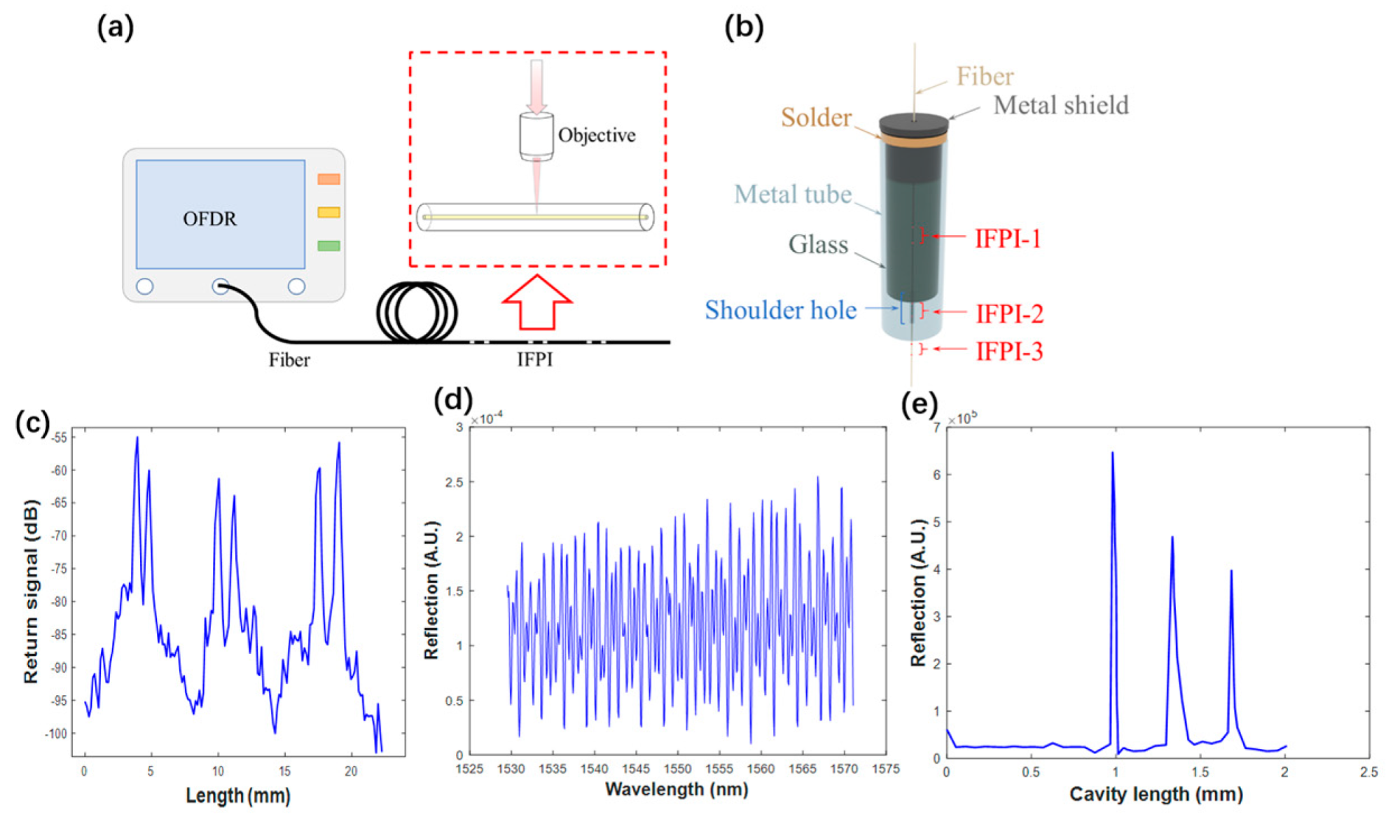
Figure 1. (a) The fabrication of IFPI; (b) The 3D-diagram of IFPI with the glass package installed in the metal tube; (c) the Rayleigh backscattering profile of the multiplexed IFPIs; (d) the spectrum of the multiplexed IFPI array; and (e) the FFT spatial domain of the spectrum.
Photonics 11 00792 g001
Figure 2. (a) The experimental setup of the glass package fabrication; (b) the pressure test setup for IFPI with the glass package.
Photonics 11 00792 g002
Figure 3. (a) The meshing grid of the fiber-glass-metal structure; (b) the fine grid and joint of the glass package and fiber core; (c) the contour of numerical results after the fabrication process; (d) the strain distribution in the fiber core.
Photonics 11 00792 g003
Figure 4. The monitored residual strain of IFPIs during the manufacturing process and corresponding finite element modeling (FEM) results. (a) overall sensors’ cavity change during the embedment process; (b) temperature sensor 2 cavity change during the embedment process; (c) temperature sensor 1 cavity change during the embedment; (d) strain sensor cavity change during the embedment process; (e) residual strain demodulation of the strain sensor.
Photonics 11 00792 g004
Figure 5. The leakage rate of IFPI with a glass sealant package under (a) high-temperature environments and (b) high-pressure environments.
Photonics 11 00792 g005
Table 1. Composition of GL1732P sealing glass powder.
CompoundComposition (mol%)
P2O567
ZnO10
K2O6
Disclaimer/Publisher’s Note: The statements, opinions and data contained in all publications are solely those of the individual author(s) and contributor(s) and not of MDPI and/or the editor(s). MDPI and/or the editor(s) disclaim responsibility for any injury to people or property resulting from any ideas, methods, instructions or products referred to in the content.