Communication

Temperature-Insensitive Ferrofluid-Clad Microfiber Bragg Grating for Magnetic Field Sensing

1
Key Laboratory of Optoelectronics and Telecommunication of Jiangxi Province, Department of Photoelectric Information Science and Engineering, Jiangxi Normal University, Nanchang 330022, China
2
School of Computer and Communication Engineering, Changsha University of Science and Technology, Changsha 410114, China
3
School of Mechatronic Engineering, China University of Mining and Technology, Xuzhou 221116, China
*
Author to whom correspondence should be addressed.
Photonics 2023, 10(3), 249; https://doi.org/10.3390/photonics10030249
Submission received: 23 January 2023 / Revised: 17 February 2023 / Accepted: 21 February 2023 / Published: 26 February 2023
(This article belongs to the Special Issue Optical Measurement Systems and Instruments)

Abstract

:
In this paper, a temperature-insensitive ferrofluid (FF)-clad microfiber Bragg Grating (MF-BG) magnetic field sensor is proposed. Through optimizing the diameter of MF-BG, we can effectively suppress its thermal property. The experimental research results show that when the diameter of MF-BG is ~2.94 μm, its reflection spectrum shift owing to ambient temperature change can be substantially small within the range of 20–80 °C. The thermal stable sensor has a magnetic field sensitivity of 0.667 pm/Gs with a linearity of more than 0.985 at 20 °C.

1. Introduction

Accurate monitoring of magnetic fields is of great importance in many application fields such as military, industrial, biomedical, controlled nuclear fusion and so on [1,2,3]. Magnetic field sensors based on optical fiber is highly attractive due to their unique advantages, including fast response, low attenuation, and high sensitivity. Ferrofluid (FF) is a kind of magnetic-sensitive material, which possesses remarkable optical properties such as tunable refractive index (RI) [4], birefringence effect [5], and Faraday effect [6]. Through incorporating FF, many of fiber-optic magnetic field sensors were demonstrated based on Sagnac loop interferometers [7,8], inline Mach–Zehnder interferometers [9], multimode interferometers [10], photonic crystal fibers (PCF) [11], microfiber knot resonator (MKR) [12], D-shaped fibers [13] and long period gratings [14].
Bragg gratings have been widely applied in the rapidly growing field of optical sensors [15,16,17,18]. As one of most popular sensing elements fiber Bragg grating (FBG) can measure a series of physical quantities including temperature [19], humidity [20], pressure [21], strain [22], etc. Profiting from the tunable RI of FF, several magnetic field sensors based on different FBG structures, such as normal FBG [23], etched FBG [24], tilted FBG [25,26], phase-shifted FBG [27], tapered FBG [28], and FBG written on a multi-clad fiber [29] have been proposed. However, since FBGs are sensitive to both ambient RI and temperature, this may lead to large cross-sensitivity and cause great errors in measurement. Therefore, removing the temperature instability is a concern associated with the developing FBG-based sensors for magnetic field measurement.
Recently, microfiber Bragg grating (MF-BG), which is an optical waveguide device with a diameter on the order of micrometers or nanometers, has attracted a lot of attention because there is a large evanescent field outside the fiber which make it very sensitive to the environment [30]. Additionally, temperature-insensitive MF-BG can be realized by the use of a cladding with a negative thermo-optic coefficient to compensate the RI change and thermal expansion of glass fiber through evanescent field interactions [31]. In this study, we theoretically designed and experimentally realized a temperature-insensitive MF-BG-based magnetic field sensor by adjusting the microfiber (MF) diameter properly. The advantages of the demonstrated sensor include high magnetic field sensitivity, good thermal stability, and compact size.

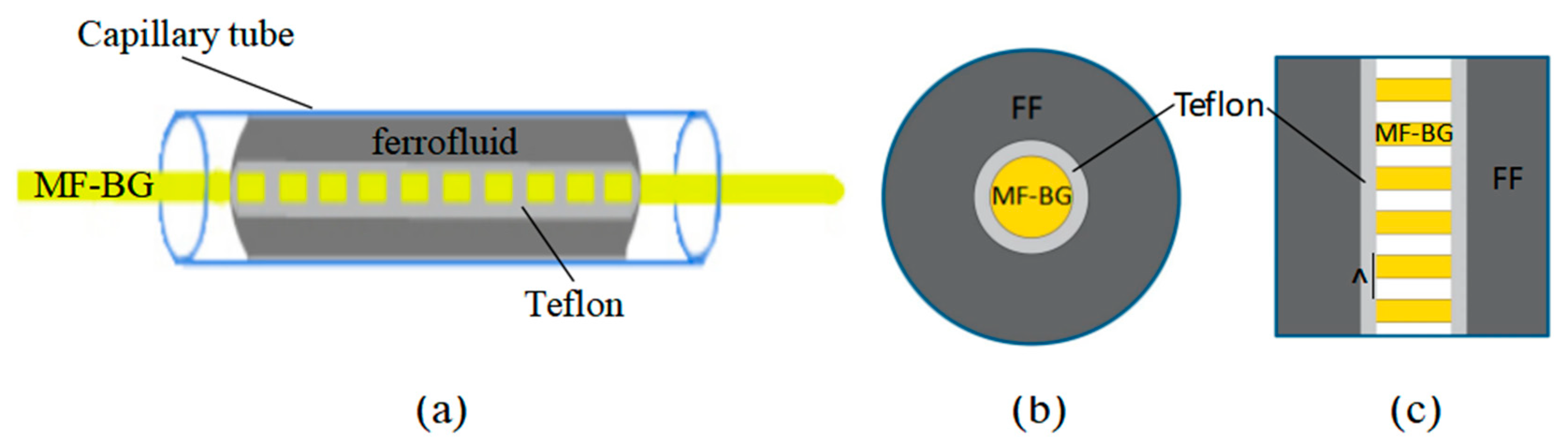
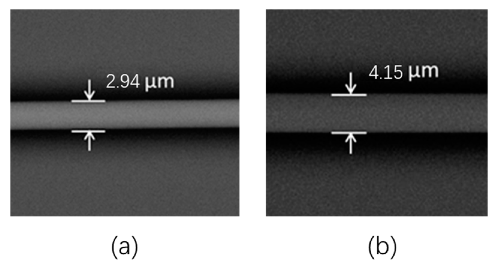
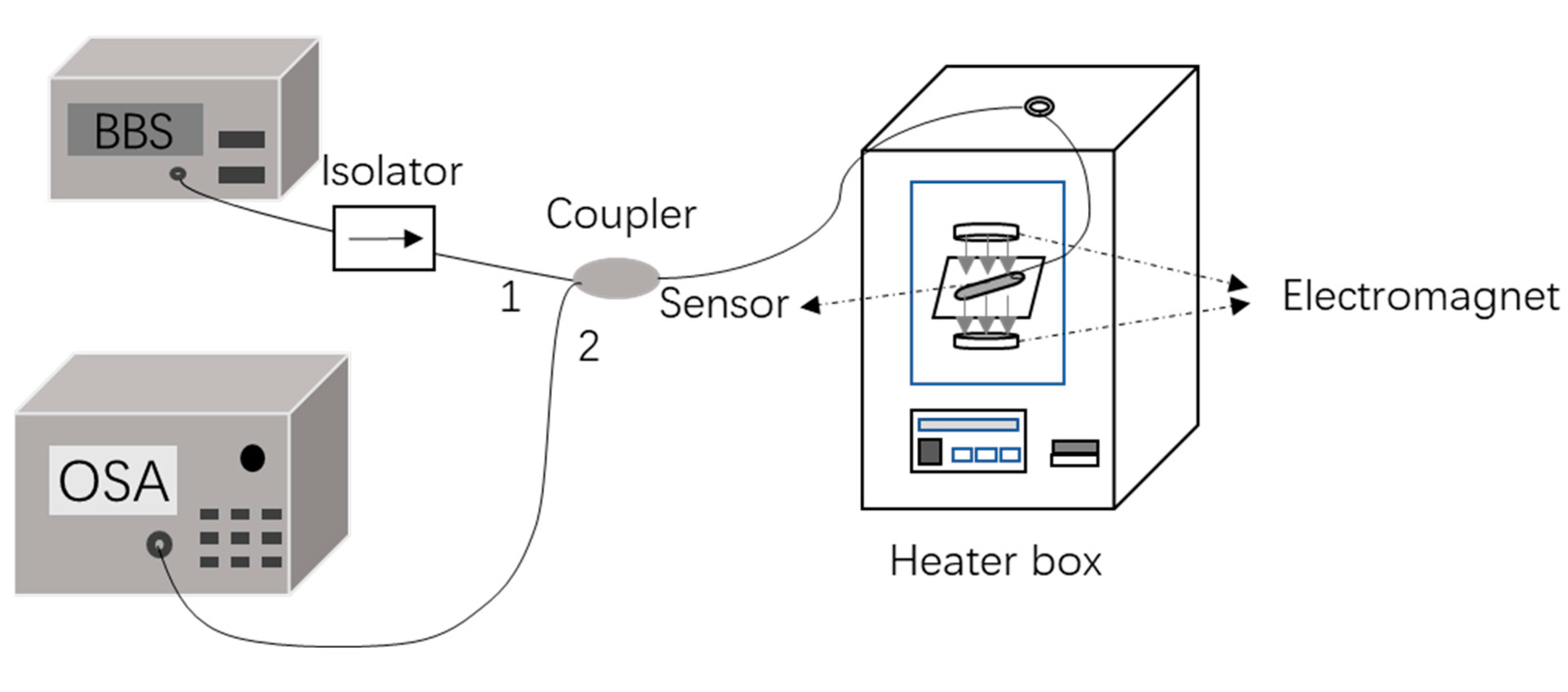
2. Device Fabrication and Working Principle

Figure 1 shows the construction of the proposed MF-BG-based magnetic field sensor. First, a standard single-mode fiber (SMF) was stretched to a MF with a specific diameter through flame heating technique [32]. Then, Bragg grating with a period of 550 nm was inscribed in the MF by ultraviolet (UV) laser radiation using the scanned phase-mask technique [30]. Through dip coating method [12], a uniform Teflon film was coated on the surface of the MF to protect the MF-BG. The dip coating method can be divided into three steps. First, immersing MF-BG in Teflon solution for a period of time, then quickly pulling out wet MF-BG and drying in an oven at 50 °C. After solvent evaporation, Teflon was deposited on the surface of MF-BG. The Teflon from DuPont has a low RI (about 1.31 at the wavelength of 1550 nm), that can prevent energy leakage of evanescent field. Figure 2a,b show SEM photographs of MF-BGs without and with Teflon coating, respectively. As we can see from the figure that the diameter of the MF-BG is 2.94 μm and the thickness of Teflon film is about 605 nm. Finally, the Teflon coated MF-BG was placed in an FF (EMG605, from Ferrotec, Hangzhou, China) filled capillary tube with length being 5 cm and inner diameter being 0.1 mm.
The reflected wavelength λB of a MF-BG can be expressed as [33]
λ B = 2 n e f f Λ
where neff represents the RI of the fundamental mode and Λ is the grating pitch. From Equation (1), we know that λB changes with neff.
When MF-BG is immersed in FF, the evanescent wave of MF-BG will be transmitted in FF. The RI of FF changes with the variations of external magnetic field strength, which will cause the change in the RI of the guided mode (neff) along MF-BG. According to Equation (1), it is obvious that the reflected wavelength λB will shift with the change in the applied magnetic field.
As well as external magnetic field, environmental temperature may also influence the RI of FF due to thermo-optic effects, which lead to cross-sensitivity and measurement errors. In order to solve the problem, the influence of the proposed sensor configuration parameters on its thermal effects was investigated.
The temperature sensitivity of the waveguide structure composed of the MF-BG “core”, Teflon “overlay”, and FF “cladding” can be expressed by
d λ B d T = λ B 1 Λ · d Λ d T + 1 n e f f · d n e f f d T
For Equation (2), we see
d n e f f d T = n e f f n M F η M F + n e f f n T e f l o n η T e f l o n + n e f f n F F η F F + n e f f d M F d M F σ M F + n e f f d T e f l o n d T e f l o n σ T e f l o n
and
d Λ Λ d T = σ M F + ξ σ T e f l o n
where n M F , n T e f l o n , and n F F are the RI of the MF, Teflon, and FF, respectively. d M F is the diameter of MF and d T e f l o n is the thickness of the Teflon overlay. η M F and σ T e f l o n are the thermal-optic and thermal expansion coefficients of the MF, respectively. η T e f l o n , η F F , and σ T e f l o n , σ F F are that of Teflon and FF, respectively. ξ represents the additional MF-BG length caused by the thermal expansion effects of Teflon, which are very small and can be ignored [12].
At 20 °C, the RI of MF-BG, Teflon, and FF are n M F = 1.4447 ,   n T e f l o n = 1.311 ,   a n d   n F F = 1.36 , respectively. The thermal–optic coefficients of MF-BG, Teflon, and FF are η M F = 1.1 × 10 5 / ,   η T e f l o n = 1.3 × 10 4 / ,   and   η F F = 2.4 × 10 4 / , respectively [12]. The thermal expansion coefficients of MF-BG and Teflon are σ M F = 5 × 10 7 / and σ T e f l o n = 8 × 10 5 / , respectively [12]. From Equations (2)–(4), we know that the value of d λ B / d T depends on n e f f / n M F , n e f f / n T e f l o n , n e f f / n F F , n e f f / d M F , n e f f / d T e f l o n , and σ M F , which are all positive. Note that the functional material FF and the packing material Teflon are both with negative thermal-optic coefficient, which can balance the positive thermal effects of MF-BG that contribute from the RI change of silica fiber and grating elongation. Based on the fiber mode theory, the value of n e f f / n M F , n e f f / n T e f l o n , and n e f f / n F F are determined by the transverse RI profile of the three-layer waveguide. Consequently, it is possible to obtain temperature insensitivity by optimizing the MF diameter.
We calculate the value of n e f f / n M F , n e f f / n T e f l o n , n e f f / n F F , n e f f / d M F , n e f f / d T e f l o n for different MF diameters as shown in Figure 3a. As the MF diameter increases from 2 μm to 9 μm, the derivative of n e f f with respect to n M F also increases until it approaches 1, whereas that the derivative of n e f f with respect to n T e f l o n , n F F , and d M F decreases until it approaches 0. When MF-BG diameter is larger than 9 μm, the derivative of n e f f with respect to all of the above parameters are almost unchanged. In the whole process, the derivative of n e f f with respect to d T e f l o n is approximately being zero. Thus, the thermal effect of the proposed sensor highly depends on the MF diameter when it is less than 9 μm. Substituting Equations (3) and (4) into Equation (2), the relationship between d λ B / d T and the MF diameter can be achieved in Figure 3b. When the MF-BG diameter is 2 μm, the temperature sensitivity is −33.98 pm/°C. As the diameter increases to 2.8896 μm, the sensitivity to temperature changes almost linearly to −1 pm/°C. In the diameter range of 2.8896–2.997 μm, the reflected wavelength shift is within ±1 pm/°C. When MF-BG diameter increases from 2.997 μm to 8.4 μm, the temperature sensitivity rises to 17.3 pm/°C. After that, the MF-BG diameter affects the temperature sensitivity little. Consequently, the MF-BG-based magnetic field sensor can be made temperature-insensitive in an inherent manner.
Furthermore, the reflected spectrum shift of the sensor from 0 °C to 80 °C with different diameters is also calculated in Figure 4. Consistent with the above theoretical analysis, the temperature sensitivity of 10 µm MF-BG is 17.7 pm/°C, showing that the temperature sensitivity has been overbalanced. In contrast, the temperature sensitivity of 2 µm MF-BG is −33.98 pm/°C, which is the underbalanced grating. When MF-BG diameter is 2.94 µm, the central wavelength of the reflection spectrum changes little.

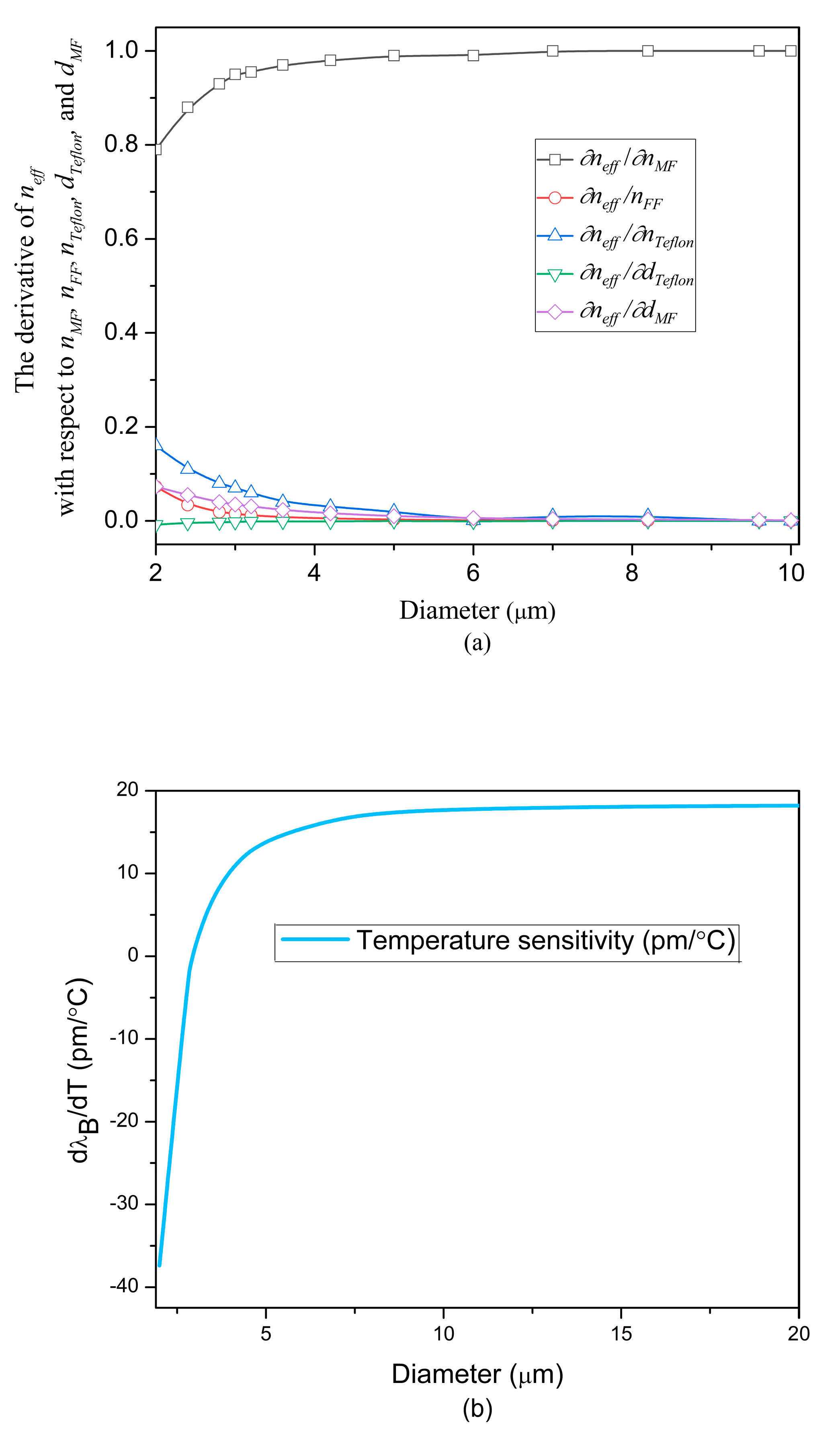
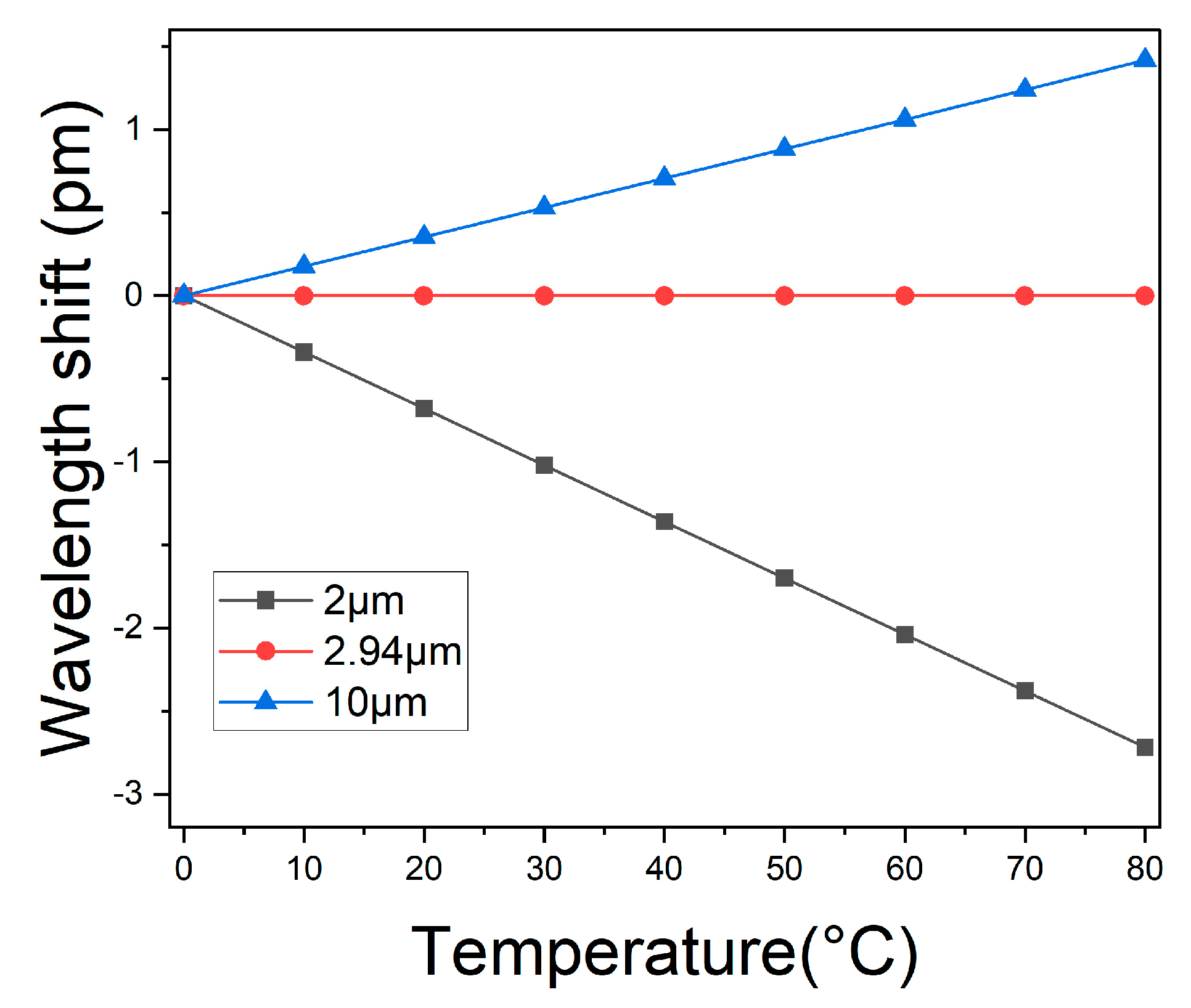
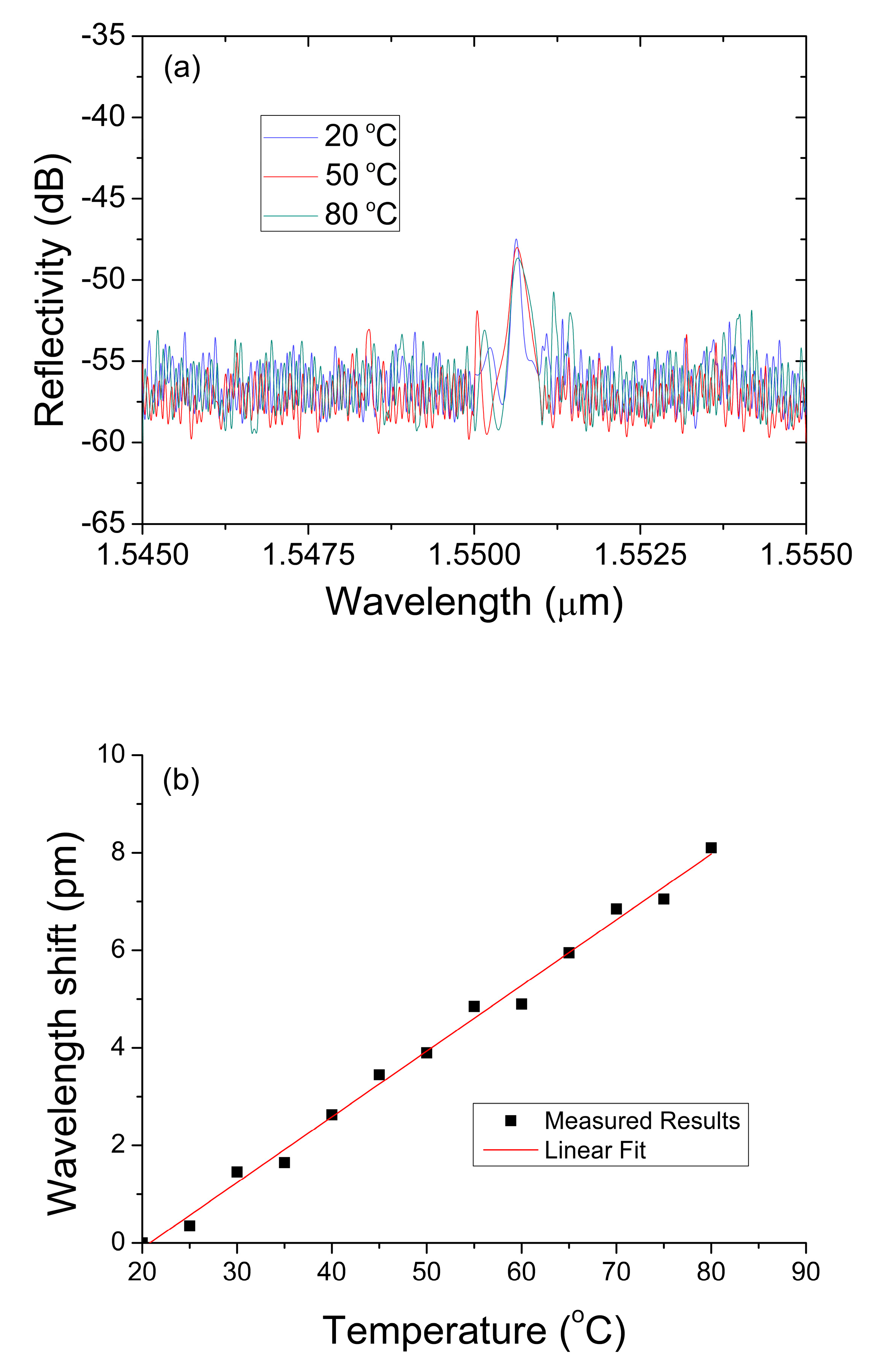
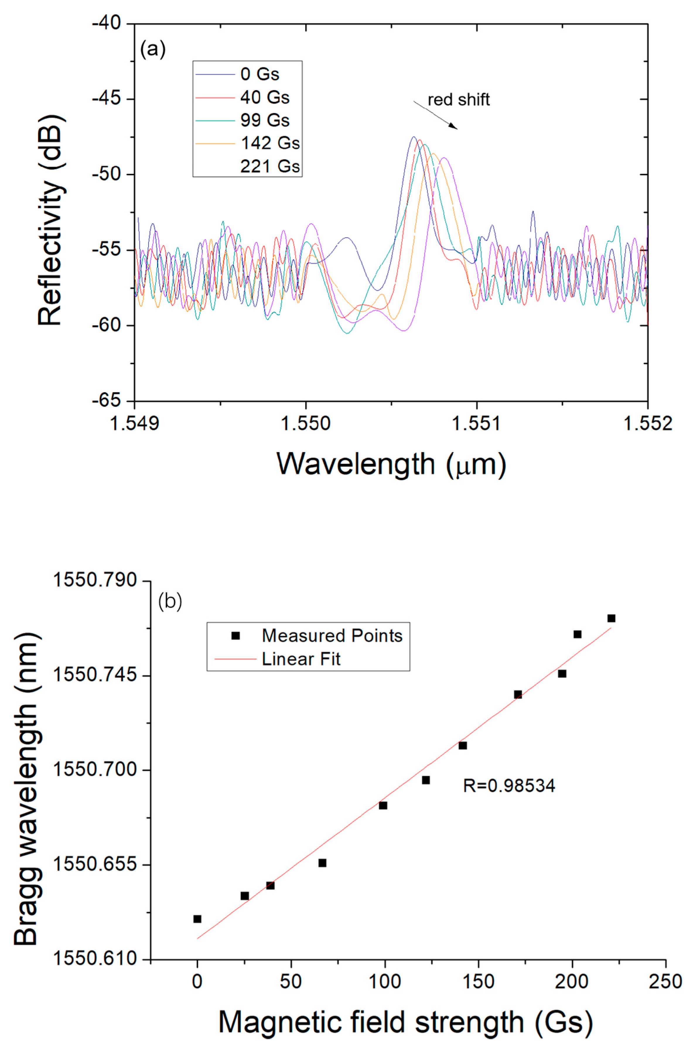
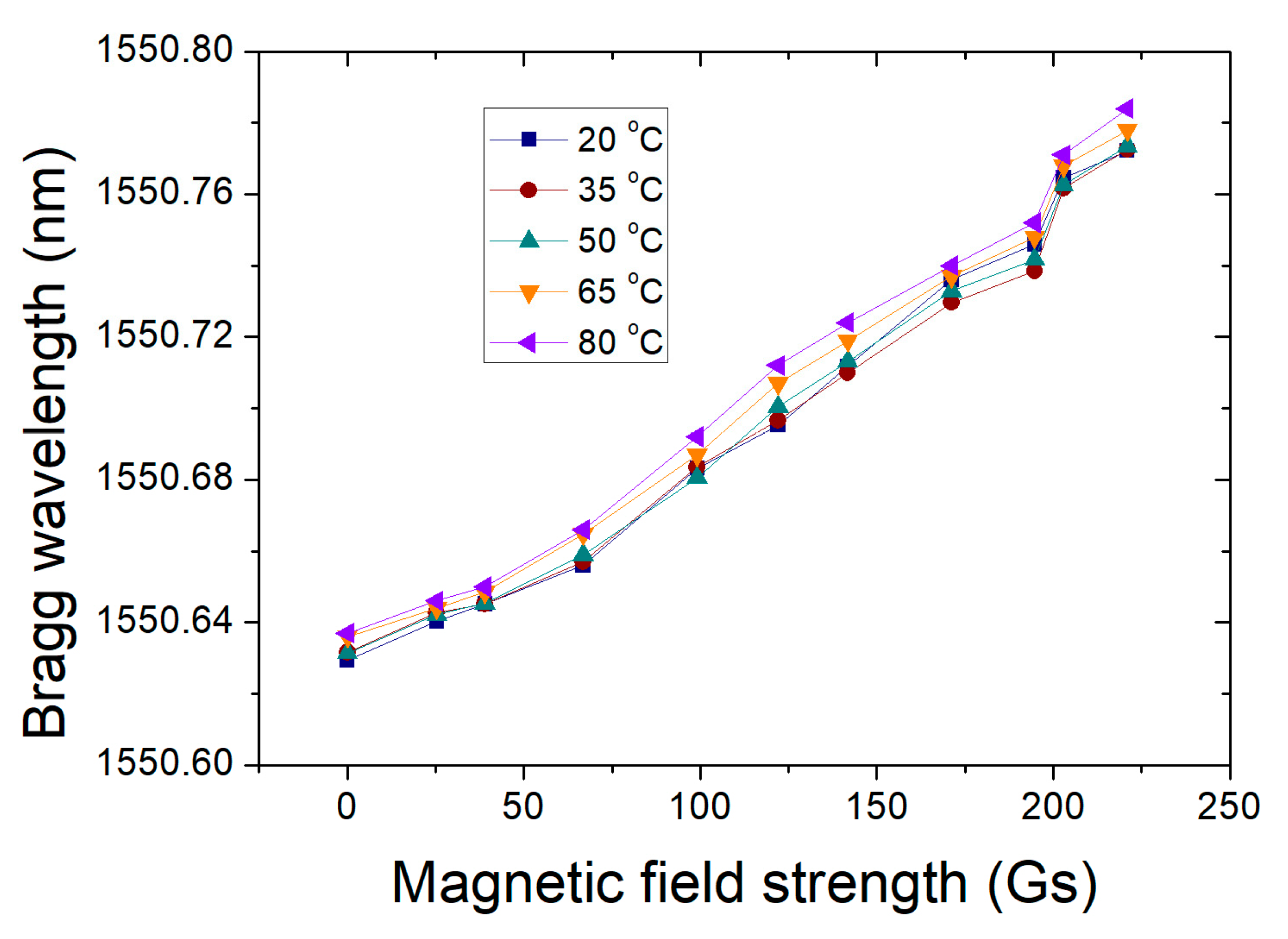
3. Experimental Results

Experiments were conducted to verify the proposed magnetic field sensor. A sensor with a MF-BG diameter of ~2.94 μm was fabricated and the reflected spectra responses to both the ambient temperature and the applied magnetic field were characterized. The experimental setup includes a broadband light source, an optical isolator, a 3-dB coupler, electromagnets, a heater box, and an optical spectrum analyzer, which is shown in Figure 5. The ambient temperature is controlled by the heater box and the magnetic field is generated by electromagnets.
The reflected spectrum shift of the sensor at different ambient temperature is shown in Figure 6. As we can see from the figure, the Bragg wavelength λB shifts slightly as the temperature went up. When the temperature increased from 20 °C to 80 °C, the reflected wavelength shifted only 8 pm. In other words, the temperature response sensitivity of the Bragg wavelength is about 0.13 pm/°C when the MF-BG diameter is 2.94 μm in our experiment.
Furthermore, we investigated the impact of the external magnetic field on the reflected spectra of the sensor when the environment temperature is 20 °C, as shown in Figure 7a. It indicates that the central wavelength of MF-BG reflected spectra shifts towards the longer wavelength with the increase in the external magnetic field. When the magnetic field is 0 Gs, 40 Gs, 99 Gs, 142 Gs, and 221 Gs, the corresponding Bragg wavelength is 1550.63 nm, 1550.66 nm, 1550.70 nm, 1550.73 nm, and 1550.78 nm, respectively. The linearity is more than 0.985, as shown in Figure 7b. In addition, the Bragg wavelength of the sensor versus the external magnetic field at different temperatures is observed in Figure 8. It is indicated that, under different temperatures, the response of the sensor to the applied magnetic field is almost consistent. It further verifies that the proposed magnetic field sensor can be made temperature-insensitive by adjusting the MF-BG diameter within an appropriate range. The reflected wavelength shifts almost linearly as the magnetic field increased 0 Gs to 221 Gs with the sensitivity of 0.667 pm/Gs. As a result, the temperature cross-sensitivity induced error in measurement can be calculated to be 0.2 Gs/°C.

4. Conclusions

We have presented a temperature-insensitive magnetic field sensor based on MF-BG coated with FF. The theoretical analysis show that the thermal effect of the sensor strongly depends on the MF-BG diameter. When MF-BG is in the range of 2.889–2.997 μm, the response of the sensor to temperature can be effectively suppressed. Experimental research results indicate that a MF-BG with diameter of 2.94 μm has an ultralow temperature sensitivity of ~0.13 pm/°C as the temperature changes within 20–80 °C. The Bragg wavelength of the sensor red-shifted by ~146 pm when the applied magnetic field increased from 0 Gs to 221 Gs. The temperature cross-sensitivity is as low as 0.2 Gs/°C. The performance comparison between the MF-BG magnetic field sensors in our work with other reported fiber structures is shown in Table 1. Since the FF did not generate additional birefringence due to environmental stress or temperature, the sensor has high stability and reproducibility. The proposed sensor has potential application in high-accuracy magnetic field measurement.

Author Contributions

Conceptualization and methodology, H.L., Y.L. and L.N.; software, validation and writing—original draft preparation, H.L., Z.W. and X.G.; data analysis, H.L.; investigation, L.N. and Y.W.; writing—review and editing, H.L., G.L. and J.Z.; funding acquisition, J.Z., S.X. and H.L.; All authors have read and agreed to the published version of the manuscript.

Funding

This work is supported by National Natural Science Foundation of China (Grants 51567011, 11804133), the Science and Technology Key Project of Education Department of Jiangxi Province (Grant No. GJJ2200306), the Science Research Fund of Hunan Provincial Education Department of China (Grant No. 22B0324).

Institutional Review Board Statement

Not applicable.

Informed Consent Statement

Not applicable.

Data Availability Statement

The data are available upon request.

Conflicts of Interest

The authors declare no conflict of interest.

References

  1. Zhou, B.; Lu, C.; Mao, B.-M.; Tam, H.-Y.; He, S. Magnetic field sensor of enhanced sensitivity and temperature self-calibration based on silica fiber Fabry-Perot resonator with silicone cavity. Opt. Express 2017, 25, 8108–8114. [Google Scholar] [CrossRef] [PubMed]
  2. Chen, Y.; Han, Q.; Liu, T.; Lan, X.; Xiao, H. Optical fiber magnetic field sensor based on single-mode-multimode-single-mode structure and magnetic fluid. Opt. Lett. 2013, 38, 3999–4001. [Google Scholar] [CrossRef] [PubMed]
  3. Tian, Q.; Feng, Z.; Rong, Q.; Wan, Y.; Qiao, X.; Hu, M.; Yang, H.; Wang, R.; Shao, Z.; Yang, T. A temperature-independent fibre-optic magnetic-field sensor using thincore fibre tailored fibre Bragg grating. Opt. Commun. 2017, 393, 169–172. [Google Scholar] [CrossRef]
  4. Horng, H.E.; Chen, C.S.; Fang, K.L.; Yang, S.Y.; Chieh, J.J.; Hong, C.-Y.; Yang, H.C. Tunable optical switch using magnetic fluids. Appl. Phys. Lett. 2004, 85, 5592–5594. [Google Scholar] [CrossRef] [Green Version]
  5. Zu, P.; Chan, C.C.; Koh, G.W.; Lew, W.S.; Jin, Y.; Liew, H.F.; Wong, W.C.; Dong, X. Enhancement of the sensitivity of magneto-optical fiber sensor by magnifying the birefringence of magnetic fluid film with Loyt-Sagnac interferometer. Sens. Actuators B Chem. 2013, 191, 19–23. [Google Scholar] [CrossRef]
  6. Yang, S.Y.; Horng, H.; Hong, C.; Yang, H.C. Structures, optical properties and properties and potentially electro-optical applications of magnetic fluid films. Tamkang J. Sci. Eng. 2002, 5, 85–93. [Google Scholar]
  7. Wei, F.; Liu, D.; Mallik, A.K.; Farrell, G.; Wu, Q.; Peng, G.-D.; Semenova, Y. Temperature-compensated magnetic field sensing with a dual-ring structure consisting of microfiber coupler-Sagnac loop and fiber Bragg grating-assisted resonant cavity. Appl. Opt. 2019, 58, 2334–2339. [Google Scholar] [CrossRef]
  8. Lv, F.; Han, C.; Ding, H.; Wu, Z.; Li, X. Magnetic Field Sensor Based on Microfiber Sagnac Loop Interferometer and Ferrofluid. IEEE Photon. J. 2015, 27, 2327–2330. [Google Scholar] [CrossRef]
  9. Li, Z.; Liao, C.; Song, J.; Wang, Y.; Zhu, F.; Dong, X. Ultrasensitive magnetic field sensor based on an in-fiber Mach–Zehnder interferometer with a magnetic fluid component. Photon. Res. 2016, 4, 197–201. [Google Scholar] [CrossRef] [Green Version]
  10. Zhu, R.-Z.; Wan, S.-J.; Xiong, Y.-F.; Feng, H.-G.; Chen, Y.; Lu, Y.; Xu, F. Magnetic Field Sensing Based on Multimode Fiber Specklegrams. IEEE J. Light. Technol. 2021, 39, 3614–3619. [Google Scholar] [CrossRef]
  11. Zu, P.; Chan, C.; Lew, W.; Hu, L.; Jin, Y.; Liew, H.; Chen, L.; Wong, W.; Dong, X. Temperature-insensitive magnetic field sensor based on nanoparticle magnetic fluid and photonic crystal fiber. IEEE Photon. J. 2012, 4, 491–498. [Google Scholar]
  12. Li, X.; Ding, H. Temperature Insensitive Magnetic Field Sensor Based on Ferrofluid Clad Microfiber Resonator. IEEE Photon. Technol. Lett. 2014, 26, 2426–2429. [Google Scholar] [CrossRef]
  13. Ying, Y.; Zhang, R.; Si, G.; Wang, X.; Qi, Y. D-shaped titled fiber Bragg grating using magnetic fluid for magnetic field sensor. Opt. Commun. 2017, 405, 228–232. [Google Scholar] [CrossRef]
  14. Zhang, N.M.Y.; Dong, X.; Shum, P.; Hu, D.; Su, H.; Lew, W.; Wei, L. Magnetic field sensor based on magnetic-fluid-coated long-period fiber grating. J. Opt. 2015, 17, 065402. [Google Scholar] [CrossRef]
  15. Sahu, S.; Ali, J.; Yupapin, P.P.; Singh, G.; Grattan, K.T.V. High-Q and temperature stable photonic biosensor based on grating waveguides. Opt. Quantum Electron. 2018, 50, 307. [Google Scholar] [CrossRef]
  16. Sahu, S.; Ali, J.; Yupapin, P.P.; Singh, G. Optical biosensor based on a cladding modulated grating waveguide. Optik 2018, 166, 103–109. [Google Scholar] [CrossRef]
  17. Prabhathan, P.; Murukeshan, V.M.; Jing, Z.; Ramana, P.V. Compact SOI nanowire refractive index sensor using phase shifted Bragg grating. Opt. Express 2009, 17, 15330–15341. [Google Scholar] [CrossRef]
  18. Sahu, S.; Ali, J.; Singh, G. Refractive index biosensor using sidewall gratings in dual-slot waveguide. Opt. Commun. 2017, 402, 408–412. [Google Scholar] [CrossRef]
  19. Gunawardena, D.S.; Cheng, X.; Cui, J.; Edbert, G.; Lu, L.; Ho, Y.T.; Tam, H.-Y. Regenerated polymer optical fiber Bragg gratings with thermal treatment for high temperature measurements. Photon. Res. 2022, 10, 1011–1021. [Google Scholar] [CrossRef]
  20. D’Amato, R.; Polimadei, A.; Terranova, G.; Caponero, M.A. Humidity sensing by chitosan-coated fiber Bragg gratings (FBG). Sensors 2021, 21, 3348. [Google Scholar] [CrossRef]
  21. Abro, Z.A.; Hong, C.; Zhang, Y.; Siddiqui, M.; Abbasi, A.; Abro, Z.; Tariq, S.Q.B. Development of FBG pressure sensors using FDM technique for monitoring sleeping postures. Sens. Actuators A Phys. 2021, 331, 112921. [Google Scholar] [CrossRef]
  22. Kuse, N.; Ozawa, A.; Kobayashi, Y. Static FBG strain sensor with high resolution and large dynamic range by dual-comb spectroscopy. Opt. Express 2013, 21, 11141–11149. [Google Scholar] [CrossRef] [PubMed]
  23. Zheng, J.; Dong, X.; Zu, P.; Ji, J.; Su, H. Intensity-modulated magnetic field sensor based on magnetic fluid and optical fiber gratings. Appl. Phys. Lett. 2013, 103, 183511. [Google Scholar] [CrossRef]
  24. Dai, J.; Yang, M.; Li, X.; Liu, H.; Tong, X. Magnetic field sensor based on magnetic fluid clad etched fiber Bragg grating. Opt. Fiber Technol. 2011, 17, 210–213. [Google Scholar] [CrossRef]
  25. Zheng, J.; Dong, X.; Zu, P.; Shao, L.Y.; Chan, C.; Cui, Y.; Shum, P.P. Magnetic field sensor using tilted fiber grating interacting with magnetic fluid. Opt. Express 2013, 21, 17863–17868. [Google Scholar] [CrossRef] [PubMed]
  26. Yang, D.; Xu, L.D.Z.; Jiang, Y.; Xu, J.; Wang, M.; Bai, Y.; Wang, H. Magnetic field sensing based on tilted fiber Bragg grating coated with nanoparticle magnetic fluid. Appl. Phys. Lett. 2014, 104, 061903. [Google Scholar] [CrossRef]
  27. Bao, L.; Dong, X.; Zhang, S.; Shen, C.; Shum, P.P. Magnetic Field Sensor Based on Magnetic Fluid-Infiltrated Phase-Shifted Fiber Bragg Grating. IEEE Sens. J. 2018, 18, 4008–4012. [Google Scholar] [CrossRef]
  28. Ruan, Z.; Pei, L.; Ning, T.; Wang, J.; Wang, J.; Li, J.; Xie, Y.; Zhao, Q.; Zheng, J. Simple structure of tapered FBG filled with magnetic fluid to realize magnetic field sensor. Opt. Fiber Technol. 2021, 67, 102698. [Google Scholar] [CrossRef]
  29. Bao, W.; Qiao, X.; Rong, Q.; Chen, F. Fiber-Optic Vector Magnetometer Based on Magnetic Fluid and Fiber Bragg Grating Written on a Multi-Clad Fiber. IEEE Sens. J. 2018, 18, 7486–7491. [Google Scholar] [CrossRef]
  30. Nie, L.; Wu, Y.; Gao, X.; Luo, H.; Li, X.; Wang, X.; Liu, G. Optimized optical tunable microfiber-Bragg grating. Optik 2022, 270, 170086. [Google Scholar] [CrossRef]
  31. Gao, S.; Jin, L.; Ran, Y.; Sun, L.-P.; Li, J.; Guan, B.-O. Temperature compensated microfiber Bragg gratings. Opt. Express 2012, 20, 18281–18286. [Google Scholar] [CrossRef] [PubMed]
  32. Luo, H.; Li, X.; Zou, W.; Jiang, W.; Chen, J. Modal Interferometer Based on a C-Shaped Ultrathin Fiber Taper for High-Sensitivity Refractive Index Measurement. Appl. Phys. Express 2012, 5, 012502. [Google Scholar] [CrossRef]
  33. Kersey, A.D.; Davis, M.A.; Patrick, H.J.; LeBlanc, M.; Koo, K.P.; Askins, C.G.; Friebele, E.J. Fiber grating sensors. IEEE J. Light. Technol. 1997, 15, 1442–1463. [Google Scholar] [CrossRef] [Green Version]
Figure 1. (a) The schematic diagram of the proposed MF sensor. (b,c) are the top view and cross-section of the structure.
Photonics 10 00249 g001
Figure 2. SEM photographs of the MF-BGs (a) without and (b) with the Teflon coating.
Photonics 10 00249 g002
Figure 3. (a) The derivative of n e f f with respect to n M F , n F F , n T e f l o n , d T e f l o n and d M F for different MF diameters. (b) λ B / d T versus different MF diameters.
Photonics 10 00249 g003
Figure 4. Spectrum shift of the sensor from 0 °C to 80 °C with different MF-BG diameters.
Photonics 10 00249 g004
Figure 5. Diagram of the magnetic field sensing system.
Photonics 10 00249 g005
Figure 6. (a) Spectrum shift of the sensor with the MF-BG diameter being 2.94 μm under different temperatures. (b) Relation between the wavelength shift and the temperature.
Photonics 10 00249 g006
Figure 7. (a) Reflected spectra versus different magnetic field intensity. (b) Relation between the Bragg wavelength and the magnetic field strength.
Photonics 10 00249 g007
Figure 8. The Bragg wavelength varies with the applied magnetic field at different temperatures.
Photonics 10 00249 g008
Table 1. Performance of FF-based fiber sensors compared with other works.
Ref.Sensor
Structure
Measurement
Range
SensitivityTemperature
Range
Temperature
Sensitivity
[11]PCF300–500 Gs2.367 pm/Gs30–100 °C3.2 pm/°C
[12]MKR0–220 Gs0.56 pm/Gs20–80 °C0.17 pm/°C
[25,26]Tilted FBG0–190 Gs0.451 pm/Gs20–60 °C8.4 pm/°C
Our workMF-BG0–221 Gs0.667 pm/Gs20–80 °C0.13 pm/°C
Disclaimer/Publisher’s Note: The statements, opinions and data contained in all publications are solely those of the individual author(s) and contributor(s) and not of MDPI and/or the editor(s). MDPI and/or the editor(s) disclaim responsibility for any injury to people or property resulting from any ideas, methods, instructions or products referred to in the content.

