Abstract
A digital micromirror device (DMD) has a wide range of applications in holographic display, light field manipulation, etc., due to its high-speed refresh rates. In order to precisely control the wavefront, the influence of the micromirror array structure of the DMD requires careful analysis. Based on an accurate three-dimensional phase model of DMD, we analyzed the diffraction characteristics of DMD. The model was established by accurately describing the phase distribution along each micromirror surface direction, and the distance between the point on the micromirror and the diffraction plane. The results showed that the orders of the DMD are the results of two groups of micromirrors interfering with each other, and a slight offset occurs when the incidence angle is twice the micromirror tilt angle, which can be removed by adjusting the incidence angle. The phase distribution results showed the main order of the DMD with all micromirrors in the on state can be approximated as a plane wave, which means that the hologram can be normally loaded on the DMD without worrying about phase disturbance from the micromirror array structure. This provides great convenience for computer holography based on DMD. Numerical simulations and experiments demonstrated the effectiveness of the work.
1. Introduction
Computer holography has widespread applications in many fields, such as three-dimensional (3D) displays [1,2,3], light field manipulation [4], and structured light generation [5]. The technology generates holograms based on diffraction algorithms, and uses a spatial light modulator (SLM) to modulate the incident wavefront. Two types of SLMs are often used in these works: liquid crystal on silicon (LCOS) SLM and a digital micromirror device (DMD) based on micro-electromechanical systems (MEMS). Although the LCOS-based SLM is currently the main device used in holography, its low refresh rate limits its application. In applications where high speed is required, such as high-resolution and large field-of-view holographic displays, high-speed light field manipulation, etc., the binary DMD has more advantages due to its extremely high refresh rate and high space-bandwidth product expansion capability [6,7,8,9,10,11]. Therefore, in these applications, it is highly necessary to extensively analyze the influence of DMD on the diffraction field. The phase DMD that has appeared in recent years makes it possible to realize multi-level phase modulation with ultra-high refresh rates. However, due to the immaturity of the technology, the reported phase DMD can only offer up to 16 discrete levels of phase control at a frame rate of 1440 Hz [12,13,14,15,16]. Therefore, the advantage of the binary amplitude DMD can be sustained for a period of time.
A DMD is an array of highly reflective aluminum micromirrors, and the mirrors can be individually rotated to an on or off state [17,18]. When a hologram is loaded on the DMD for reconstruction, the unique micromirror array structure of the DMD will affect the reconstructed wavefront [19,20,21]. One study analyzed the effect of different thresholding techniques on the diffraction field [22]. Different from introducing computer holography into the DMD, the influence of the micromirror array structure of the DMD on the diffraction field also needs to be carefully analyzed. Many previous studies have analyzed the diffraction properties of the DMD. Thomas Kreis described the results of DMD used for optical reconstruction, while the phase difference between the micromirrors was neglected [23]. Some studies have considered the phase difference; however, the diffraction envelopes described by the models in these works were not accurate enough [24,25]. Some studies have analyzed DMD by developing a two-dimensional (2D) reflectance function, while there were many inconsistencies in the details of the equations among them [26,27,28,29,30]. Most studies have focused on the intensity distribution of the diffraction field of DMD, while ignoring the phase properties of the diffraction field [23,24,25,26,27,28,29,30].
In this study, we analyzed the intensity and phase properties of the diffraction field of DMD based on an accurate 3D phase model. The 3D phase model is established by accurately describing the phase distribution along each micromirror surface direction, and the distance between the point on the micromirror and the diffraction plane. We use the discrete Rayleigh-Sommerfeld diffraction integral method to calculate the diffraction field. The intensity analysis results show the position and intensity relationship between each diffraction order. The orders are the results of two groups of micromirrors interfering with each other, and a slight offset appears when the incidence angle is twice the micromirror tilt angle. When the incidence angle is suitable, this offset can be removed and the main order of the diffraction field can be exactly located on the optical axis. The phase analysis of the diffraction field shows that the main order of the DMD could be approximated as a plane wave, which means that a desired wavefront could be reconstructed without additional phase disturbance from the DMD, and that the DMD can be treated as an amplitude-only SLM. Numerical simulations and optical experiments validate our research.
2. Diffraction Characteristics Analysis
When in use, each micromirror of the DMD has two possible states (on = 1 and off = 0) corresponding to micromirror tilt angle. Only the light reflected by the micromirrors in the on state contributes to the diffraction field. For simplicity, we first analyze the diffraction characteristics of the DMD with all micromirrors in the on state. When loading a hologram on the DMD causes some of the micromirrors to be in the off state, the modulation function of the DMD could be regarded as the multiplication of the reflection function of the DMD with all micromirrors in the on state and the modulation function of the hologram.
A DMD with all micromirrors in the on state is shown in Figure 1. Figure 1a shows the 2D structure of the DMD, and Figure 1b shows the structure of the DMD along the diagonal direction -axis. and denote the horizontal and vertical resolution of the DMD, respectively. The plane is the incidence plane, and the -axis is the optical axis. denotes the incidence angle, and denotes the diffraction angle. denotes the micromirror tilt angle (relative to -axis). denotes the micromirror pitch along the -axis or the -axis, and denotes the micromirror pitch along the diagonal direction -axis or the counter-diagonal direction -axis. denotes the wavelength of the incidence light. The micromirrors can be divided into two groups, Group (blue square in Figure 1a) and Group (red square in Figure 1a), according to the phase distribution on the micromirror surface. For a point on a micromirror of the DMD, the phase of can be described by Equation (1).
where % denotes the mod operation and denotes the floor operation. We have
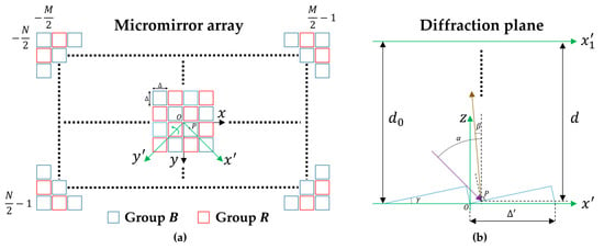
Figure 1.
The DMD with all micromirrors in the on state: (a) 2D structure; (b) 1D structure along the diagonal direction x′-axis.
The distance between the point and the diffraction plane along the direction can be described by Equation (6):
where denotes the distance between the plane and the diffraction plane along the optical axis. According to the Rayleigh-Sommerfeld diffraction theory, the diffraction field at the diffraction plane can be given by:
where denotes the amplitude of point . When the incident light is a uniform plane wave and all micromirrors of the DMD are in the on state, .
For a one-dimensional (1D) structure corresponding to the micromirrors belonging to Group along the -axis in Figure 1b, Equations (1)–(10) can be deduced as:
For a deeper understanding of the diffraction properties of the DMD, we also used the Fourier method to analyze the diffraction field of the DMD for the 1D case, and obtained similar results to the 3D phase model method. Base on the Fourier method, the modulation function of the DMD can be described by [31]:
where denotes the modulation function of a single micromirror, which can be given by:
The spectrum of the DMD can be obtained by Fourier transform:
where
3. Results and Discussion
We analyzed the amplitude and phase characteristics of the diffraction field of DMD based on the 3D phase model method. For comparison, we also show the results of the Fourier method for the 1D case. A DMD driven by the ViLUX V-9001 module is used in the research. The resolution is , and the pixel pitch is 7.56 μm.
Figure 2 shows the 1D diffraction field of the DMD with all micromirrors in the on state, corresponding to Figure 1b. The incidence angle is 24° as recommended by the DMD manufacturer, and is twice the micromirror tilt angle, 12°. The wavelength is 632.8 nm. The initial distance is 500 mm. The number of the micromirrors along the diagonal direction -axis is 1600, and the pitch is . The size of the analyzed diffraction field is five times the size of the DMD (for the 1D case), and it contains multiple diffraction orders. In order to calculate the correct diffraction field containing high order terms, encryption sampling is required in the DMD plane and the diffraction plane. The sampling intervals in the DMD plane and the diffraction plane are /10 and /4, respectively. Therefore, the number of samples in the DMD plane and the diffraction plane for the 1D case are , respectively. According to Equations (11)–(15), we calculated the diffraction fields based on the 3D phase model and the Fourier method, as shown in Figure 2. The blue dotted line and the purple dashed line represent the results of the Fourier method and the results of the 3D phase model method, respectively. The curves for the Fourier method are superposed onto the curves for the 3D phase model method, as shown in Figure 2a,c. It can be seen that the two methods obtain consistent results.
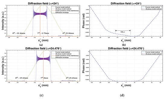
Figure 2.
The 1D diffraction field of DMD with all micromirrors in the on state: (a,b) the incidence angle α is 24°; (c,d) the incidence angle α is 24.476°.
According to the grating theory, the center position of the diffraction envelope on a micromirror is determined by the direction of the reflected light with respect to the normal state of the micromirror surface, and the envelope is symmetrically distributed around the z-axis when the incident angle is twice the micromirror tilt angle, as shown in Figure 2a. This envelope determines the relative intensities of the diffraction orders. The positions of the orders are determined by the interference field from the micromirror array. The zero order of the interference pattern is located in the direction of the reflected light with respect to the normal state of the DMD plane. Based on Equations (22) and (23), the theoretical position of the -order can be calculated, as shown in Table 1, and the order closest to the optical axis is the -order. Due to the position of the interference zero order and the interval between the interference patterns, the -order cannot be exactly located on the optical axis when the incident angle is twice the micromirror tilt angle, and there will be a slight offset, as shown in Figure 2a.

Table 1.
The center position of the -order.
Figure 2b shows the corresponding phase distribution. It can be seen that the phase distribution of the -order is close to a straight line. Table 2 shows the simulated phase difference of distance at the center of the -order, and the theoretical phase difference of a plane wave at the corresponding angle. The theoretical result can be calculated by Equation (24). It can be seen that the results are relatively consistent. This means that the main diffraction order of the DMD with all micromirrors in the on state can be approximated as a plane wave. This result is highly beneficial for computer holography, meaning that the DMD does not cause additional phase disturbances on the modulated wavefront. This also explains why the hologram calculated with a plane reference wave can be directly loaded onto the DMD and effectively work.

Table 2.
The phase difference of NΔ′ distance at the center of the Nth-order.
Computer holography systems are on-axis in many cases. However, using a DMD with an incident angle twice the micromirror tilt angle will result in a slight offset of the major diffraction order relative to the optical axis. This offset can sometimes seriously affect the reconstruction quality of the hologram. Therefore, the incident angle needs to be adjusted so that the main order can be exactly located on the optical axis, and the accurate incident angle to make -order located on the optical axis can be calculated by Equation (25). It is worth noting that the diffraction envelope will also shift when the incident angle changes. Figure 2c,d shows the diffraction field when the incident angle is adjusted to make the -order exactly located on the optical axis; the angle is 24.476°. The phase distribution becomes a horizontal line. This means that the -order could be approximated as a plane wave propagating along the optical axis.
Figure 3 shows the diffraction fields of the -order without/with considering the 3D phase model of the DMD when a rectangular aperture and a binary amplitude grating are displayed on the DMD for the 1D case. It can be seen that the micromirror array structure of the DMD does not severely disturb the diffraction field of the original object when we adjust the incident angle to make the -order exactly located on the optical axis.
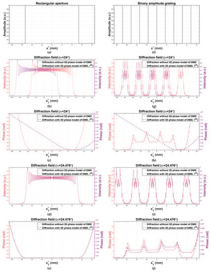
Figure 3.
The diffraction fields of the 7th-order without/with considering the 3D phase model of DMD: (a–e) the diffraction fields of a rectangular aperture; (f–j) the diffraction fields of a binary amplitude grating.
For the 2D case, the diffraction fields from Groups and micromirrors interfere with each other, resulting in a change in the diffraction field. We first show the interference results in the 1D case, as shown in Figure 4. It can be seen that the and other odd orders disappear due to interference, and the intensity of the -order becomes the highest, as shown in Figure 4a. Changing the incident angle according to Equation (25) can exactly locate the -order on the optical axis, as shown in Figure 4c. According to the phase distribution in Figure 4d, it can be seen that the -order can still be approximated as a plane wave, even in the case of Group interfering with Group . For the 2D case, the results are shown in Figure 5, and are similar to the results of the 1D case. The simulation results in Figure 5a–c and the experimental results in Figure 5d–f are in good agreement. In order to speed up the calculation, the resolution and the propagation distance in the simulation are reduced to 10% of their original values, so that the interval is also reduced to 10%. The diffraction fields of Groups and are similar, and the highest order closest to the optical axis is the -order when the incidence angle is 24°, as shown in Figure 4a,b,d,e. However, the diffraction field changes when all micromirrors are in the on state (Group Group ). The -order disappears, and the -order becomes the highest, as shown in Figure 4c,f. We can see that the diffraction order used in the holography system based on the DMD is the -order, other than the -order for the 2D case.
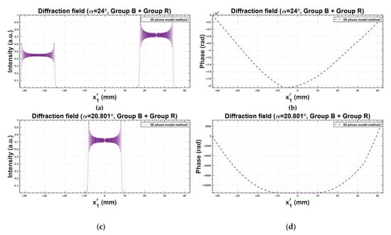
Figure 4.
The 1D diffraction fields of the Groups B and R interfering with each other: (a,b) the incidence angle α is 24°; (c,d) the incidence angle α is 20.801°.
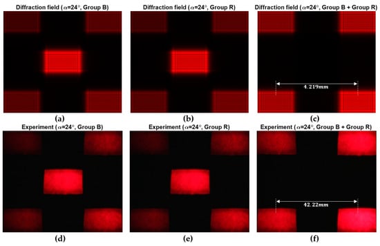
Figure 5.
The 2D diffraction fields of the Groups B, R, and B + R with the incidence angle 24°: (a–c) the simulation results; (d–f) the experiment results.
Figure 6 shows the diffraction field of the DMD with all micromirrors in the on state (Group Group ) when the -order is exactly located on the optical axis, with the incident angle 20.801° calculated by Equation (25). The offset is removed and the wavefront can be approximated as a plane wave. Figure 7 shows the diffraction fields when a rectangular aperture and a binary amplitude grating are displayed on the DMD, and the results are similar to the results of the 1D case.
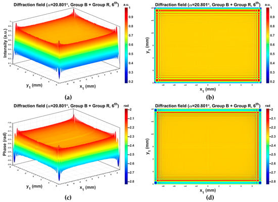
Figure 6.
The 2D diffraction field of the DMD with all micromirrors in the on state (Group B + Group R) when the 6th-order is exactly located on the optical axis: (a,b) the intensity distribution; (c,d) the phase distribution.
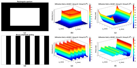
Figure 7.
The 2D diffraction fields of the 6th-order considering the 3D phase model of the DMD when the incidence angle is 20.801°: (a–c) the diffraction field of a rectangular aperture; (d–f) the diffraction field of a binary amplitude grating.
Another advantage of the DMD over the LCOS-based SLM is that it can work with non-monochromatic radiation, as shown in previous studies [32,33]. However, the 3D phase model is based on the condition that the incident light is a uniform plane wave. As a result of this, the model is not applicable when the incident light is quasi-monochromatic and spatially incoherent [32]. When the incident light contains several coherent radiation sources, the model can be used for analysis [33].
In our model, for the sake of simplification, we only analyzed the results when the DMD had no manufacturing errors (micromirror tilt angle variation, orientation of the micromirror axis-of-rotation variation, and window flatness), which made the model concise and easy to analyze. However, these manufacturing errors could cause significant deterioration of the diffraction field, as shown in [34]. The 3D phase model we proposed has the ability to accurately analyze the influence of these manufacturing errors by changing the tilt angle and other parameters. However, the analysis requires more careful work, and could be an independent research objective; we hope to study this influence in detail in the future.
4. Conclusions
We proposed an accurate 3D phase model of the DMD, and analyzed its amplitude and phase characteristics with the discrete Rayleigh-Sommerfeld diffraction integration method. We found that the main diffraction order of the DMD with all micromirrors in the on state had a slight offset from the optical axis when the DMD was illuminated at the angle twice the micromirror tilt angle, and the order we used was the result of the Groups and interfering with each other. We provided the exact incident angle for removing this offset. The phase analysis results showed that the main order of the DMD with all micromirrors in the on state could be approximated as a plane wave. It means that the micromirror array structure of the DMD will not bring additional phase disturbances in wavefront modulation. This provides great convenience for computer holography applications based on the DMD.
Author Contributions
Conceptualization, H.Z.; methodology, X.W.; investigation, X.W.; writing—original draft, X.W.; writing—review and editing, H.Z. All authors have read and agreed to the published version of the manuscript.
Funding
National Key Research and Development Program of China (No. 2021YFB2802100); National Natural Science Foundation of China (No. 62035003).
Institutional Review Board Statement
Not applicable.
Informed Consent Statement
Not applicable.
Data Availability Statement
Data underlying the results presented in this paper are not publicly available at this time but maybe obtained from the authors upon reasonable request.
Conflicts of Interest
The authors declare no conflict of interest.
References
- Benton, S.A.; Bove Jr, V.M. Holographic Imaging; John Wiley & Sons: Hoboken, NJ, USA, 2008. [Google Scholar]
- Zhang, H.; Zhao, Y.; Cao, L.; Jin, G. Three-dimensional display technologies in wave and ray optics: A review. Chin. Opt. Lett. 2014, 12, 060002. [Google Scholar] [CrossRef]
- Blinder, D.; Birnbaum, T.; Ito, T.; Shimobaba, T. The state-of-the-art in computer generated holography for 3D display. Light Adv. Manuf. 2022, 3, 572–600. [Google Scholar] [CrossRef]
- Sun, B.; Salter, P.S.; Roider, C.; Jesacher, A.; Strauss, J.; Heberle, J.; Schmidt, M.; Booth, M.J. Four-dimensional light shaping: Manipulating ultrafast spatiotemporal foci in space and time. Light Sci. Appl. 2018, 7, 17117. [Google Scholar] [CrossRef]
- Rubinsztein-Dunlop, H.; Forbes, A.; Berry, M.V.; Dennis, M.R.; Andrews, D.L.; Mansuripur, M.; Denz, C.; Alpmann, C.; Banzer, P.; Bauer, T.; et al. Roadmap on structured light. J. Opt. 2017, 19, 013001. [Google Scholar] [CrossRef]
- Fang, Z.-X.; Zhao, H.-Z.; Chen, Y.; Lu, R.-D.; He, L.-Q.; Wang, P. Accelerating polygon beam with peculiar features. Sci. Rep. 2018, 8, 8593. [Google Scholar] [CrossRef] [PubMed]
- Chlipala, M.; Kozacki, T. Color LED DMD holographic display with high resolution across large depth. Opt. Lett. 2019, 44, 4255–4258. [Google Scholar] [CrossRef] [PubMed]
- Wang, X.; Zhang, H.; Cao, L.; Jin, G. Generalized single-sideband three-dimensional computer-generated holography. Opt. Express 2019, 27, 2612–2620. [Google Scholar] [CrossRef]
- Lee, B.; Yoo, D.; Jeong, J.; Lee, S.; Lee, D.; Lee, B. Wide-angle speckleless DMD holographic display using structured illumination with temporal multiplexing. Opt. Lett. 2020, 45, 2148–2151. [Google Scholar] [CrossRef]
- Gao, H.; Wang, Y.; Fan, X.; Jiao, B.; Li, T.; Shang, C.; Zeng, C.; Deng, L.; Xiong, W.; Xia, J.; et al. Dynamic 3D meta-holography in visible range with large frame number and high frame rate. Sci. Adv. 2020, 6, eaba8595. [Google Scholar] [CrossRef]
- Li, J.; Smithwick, Q.; Chu, D. Holobricks: Modular coarse integral holographic displays. Light: Sci. Appl. 2022, 11, 57. [Google Scholar] [CrossRef]
- Bartlett, T.A.; McDonald, W.C.; Hall, J.N. Adapting Texas Instruments DLP technology to demonstrate a phase spatial light modulator. In Proceedings of the Emerging Digital Micromirror Device Based Systems and Applications XI, San Francisco, CA, USA, 4 March 2019. [Google Scholar]
- Bartlett, T.A.; McDonald, W.C.; Hall, J.N.; Oden, P.I.; Doane, D.; Ketchum, R.S.; Byrum, T. Recent advances in the development of the Texas Instruments phase-only microelectromechanical systems (MEMS) spatial light modulator. In Proceedings of the Emerging Digital Micromirror Device Based Systems and Applications XIII, Online, 9 March 2021. [Google Scholar]
- Ketchum, R.S.; Blanche, P.-A. Diffraction Efficiency Characteristics for MEMS-Based Phase-Only Spatial Light Modulator with Nonlinear Phase Distribution. Photonics 2021, 8, 62. [Google Scholar] [CrossRef]
- Douglass, M.R.; Hall, J.N.; Oden, P.I.; Byrum, T.M. Reliability assessment of the Texas Instruments phase light modulator. In Proceedings of the Emerging Digital Micromirror Device Based Systems and Applications XIV, San Francisco, CA, USA, 1 March 2022. [Google Scholar]
- Choi, S.; Gopakumar, M.; Peng, Y.; Kim, J.; O’Toole, M.; Wetzstein, G. Time-multiplexed Neural Holography: A Flexible Framework for Holographic Near-eye Displays with Fast Heavily-quantized Spatial Light Modulators. In Proceedings of the ACM SIGGRAPH 2022 Conference Proceedings, Vancouver, BC, Canada, 7–11 August 2022. [Google Scholar]
- Hornbeck, L. Deformable-Mirror Spatial Light Modulators; SPIE: Philadelphia, PA, USA, 1990; Volume 1150. [Google Scholar]
- Brennesholtz, M.S.; Stupp, E.H. Projection Displays; Wiley Publishing: Indianapolis, IN, USA, 2008. [Google Scholar]
- Son, J.-Y.; Lee, B.-R.; Chernyshov, O.O.; Moon, K.-A.; Lee, H. Holographic display based on a spatial DMD array. Opt. Lett. 2013, 38, 3173–3176. [Google Scholar] [CrossRef] [PubMed]
- Park, M.-C.; Lee, B.-R.; Son, J.-Y.; Chernyshov, O. Properties of DMDs for holographic displays Properties of DMDs for holographic displays. J. Mod. Opt. 2015, 62, 1600–1607. [Google Scholar] [CrossRef]
- Son, J.-Y.; Son, W.-H.; Kim, J.-H.; Choo, H. Image reconstruction in an electro-holographic display. J. Opt. 2017, 19, 055604. [Google Scholar] [CrossRef]
- Cheremkhin, P.A.; Kurbatova, E.A. Comparative appraisal of global and local thresholding methods for binarisation of off-axis digital holograms. Opt. Lasers Eng. 2019, 115, 119–130. [Google Scholar] [CrossRef]
- Kreis, T.; Aswendt, P.; Hoefling, R. Hologram reconstruction using a digital micromirror device. OPTICE 2001, 40, 926–933. [Google Scholar]
- Wang, D.; Wei, S. Characterization of a Digital Micromirror Device for Computer Generated Video Holography. In Proceedings of the Fourth International Conference on Image and Graphics (ICIG 2007), Chengdu, China, 22–24 August 2007; pp. 855–862. [Google Scholar]
- Scholes, S.; Kara, R.; Pinnell, J.; Rodríguez-Fajardo, V.; Forbes, A. Structured light with digital micromirror devices: A guide to best practice. OPTICE 2019, 59, 041202. [Google Scholar] [CrossRef]
- Chen, X.; Yan, B.-b.; Song, F.-j.; Wang, Y.-q.; Xiao, F.; Alameh, K. Diffraction of digital micromirror device gratings and its effect on properties of tunable fiber lasers. Appl. Opt. 2012, 51, 7214–7220. [Google Scholar] [CrossRef]
- Xiong, Z.; Liu, H.; Tan, X.; Lu, Z.; Li, C.; Song, L.; Wang, Z. Diffraction analysis of digital micromirror device in maskless photolithography system. J. Micro/Nanolithogr. MEMS MOEMS 2014, 13, 043016. [Google Scholar] [CrossRef]
- Ren, Y.-X.; Lu, R.-D.; Gong, L. Tailoring light with a digital micromirror device. Ann. Der Phys. 2015, 527, 447–470. [Google Scholar] [CrossRef]
- Han, Q.; Zhang, J.; Wang, J.; Sun, Q. Diffraction analysis for DMD-based scene projectors in the long-wave infrared. Appl. Opt. 2016, 55, 8016–8021. [Google Scholar] [CrossRef] [PubMed]
- Dong, X.; Shi, Y.; Xiao, X.; Zhang, Q.; Chen, F.; Sun, X.; Yuan, W.; Yu, Y. Non-paraxial diffraction analysis for developing DMD-based optical systems. Opt. Lett. 2022, 47, 4758–4761. [Google Scholar] [CrossRef] [PubMed]
- Casini, R.; Nelson, P.G. On the intensity distribution function of blazed reflective diffraction gratings. J. Opt. Soc. Am. A 2014, 31, 2179–2184. [Google Scholar] [CrossRef] [PubMed]
- Molodtsov, D.Y.; Rodin, V. Object recognition in non-coherent optical correlator based on DMD-modulator. In Proceedings of the Asia-Pacific Conference on Fundamental Problems of Opto-and Microelectronics, Khabarovsk, Russia, 14 December 2016. [Google Scholar]
- Stsepuro, N.; Kovalev, M.; Zlokazov, E.; Kudryashov, S. Wavelength-Independent Correlation Detection of Aberrations Based on a Single Spatial Light Modulator. Photonics 2022, 9, 909. [Google Scholar] [CrossRef]
- Molodtsov, D.Y.; Cheremkhin, P.A.; Krasnov, V.V.; Rodin, V.G. Impact of DMD-SLMs errors on reconstructed Fourier holograms quality. J. Phys. Conf. Ser. 2016, 737, 012074. [Google Scholar] [CrossRef]
Disclaimer/Publisher’s Note: The statements, opinions and data contained in all publications are solely those of the individual author(s) and contributor(s) and not of MDPI and/or the editor(s). MDPI and/or the editor(s) disclaim responsibility for any injury to people or property resulting from any ideas, methods, instructions or products referred to in the content. |
© 2023 by the authors. Licensee MDPI, Basel, Switzerland. This article is an open access article distributed under the terms and conditions of the Creative Commons Attribution (CC BY) license (https://creativecommons.org/licenses/by/4.0/).