Article

Mechanical Model and Kinematic Characteristics of the Particle Impacting Screen Plate During Flip-Flow Screening Process

1
State Key Laboratory of Mineral Processing Science and Technology, BGRIMM Technology Group, Beijing 102628, China
2
School of Chemical Engineering and Technology, China University of Mining and Technology, Xuzhou 221116, China
*
Authors to whom correspondence should be addressed.
Separations 2026, 13(4), 113; https://doi.org/10.3390/separations13040113
Submission received: 26 February 2026 / Revised: 28 March 2026 / Accepted: 3 April 2026 / Published: 5 April 2026

Abstract

Flip-flow screens are widely used for the efficient separations of wet fine materials. To explore the separation characteristics of the particle and screen plate in the flip-flow screening process, a flip-flow plate impact experimental system was built. The experimental system was based on a spherical inertial measurement device and a semi-industrial flip-flow screen system. In this study, we first derive the impact mechanics equation of the flip-flow screen plate on the particle and analyze the influence of the main parameters on the maximum impact force. Subsequently, we investigated the kinematic characteristics of the particle impacted by the screen plate at different moving positions, the variation of the centerline acceleration mechanism, and determined the angular velocity in the collision process. Additionally, we further clarified the alteration in the rules of translational and rotational kinetic energy of the particles in the collision process. This study addresses a research gap in the phenomenological modelling of particulate screening process. At the same time, it provides theoretical support for the accurate control of the flip-flow screening process.

1. Introduction

Screening is a key method for separating granular materials based on their particle size [1,2,3,4,5]. It is widely used in the field of bulk material separation in chemical engineering, metallurgy, mining, and other industries [6,7,8,9,10,11].
The traditional screening method is vibration screening. In this method, a motor generates vertical displacement excitation of the screen plate, which then acts on the particle group above the screen plate to realize particle loosening and screening [12,13]. During this process, as the lower limit of screening particle size decreases, the content of fine material increases, leading to the deterioration of the screening environment and poor screening effect. Therefore, the traditional vertical incentive method has yet to achieve efficient screening for the classification of fine materials, and the screening of fine materials has been a longstanding research hotspot [14,15,16].
In recent years, flip-flow screens have been increasingly used for the classification of fine materials [17,18,19,20,21]. The driving mechanism of this equipment achieves a high vibration intensity of the screen plate through its horizontal displacement excitation, which promotes the complete looseness of the fine particles and speeds up the stratification of the materials. In industrial applications, the structural reliability of flip-flow screens and the interaction mechanism between particles and screen plates markedly impact the screening process.
Research on the structural reliability of flip-flow screens mainly focuses on testing dynamic characteristics of screen body and the dynamic modeling of screen plate. Several models have been established to advance the understanding of the structural reliability of flip-flow screens. Those include a mathematical model for the vibration characteristics of an inclined relaxation screen plate based on catenary theory, a string vibration model for a flip-flow screen plate [22,23,24]. Furthermore, mathematical models were established to explore the dynamic characteristics of the screening equipment. A mathematical model was proposed by Zhao et al. for a double-layer vibrating inverted flow screen based on a vibration system with three degrees of freedom; and a nonlinear rubber shear spring model by Gong et al. [25,26]. Wu et al. established a complete dynamic model of the flip-flow screening system using the lumped mass method and deduced the relationship between the parameters of the material distribution model and the rotating speed using the least squares method [27]. Additionally, a steam coal separation process was proposed by Chen et al.; this process combined heavy medium vessel separation and a 3 mm dry flip-flow screening technology [28]. Yu et al. studied the 3 mm flip-flow screening technology of iron ore and explored the influence of screen plate length on screening effect [15]. Similarly, Wang et al. studied a 0.8 mm large-scale dry flip-flow screening technology for spodumene and proposed a dry wet combined desliming process for spodumene [29]. Finally, Akbari et al. optimized the separation performance technology by proposing a flip-flow screening technology based on airflow enhancement [30].
The phenomenological model of the flip-flow screening process was studied as follows: Wang et al. established a dynamic model of the flip-flow screen penetration process and explored the effects of structural parameters on the dynamic evaluation index [31]. A probability model of the flip-flow screening process was proposed, and the influence of the particle size effect on the screening effect was determined [32]. These phenomenological models are built around the screening process, and research on the interaction between the particles and screen plates is lacking. The interaction between particles and the screen plate dictates the particle motion, which is a fundamental determinant of the overall screening performance and the accuracy of the resulting phenomenological models.
On the other hand, some scholars use the discrete element method (DEM) to study the stratification of screening particles, the mechanism of screening and the influence of operating parameters, and model the particle-screen plate interaction in the process [33,34]. However, the DEM still faces inherent limitations when applied to the flip-flow screening process modeling. The computational cost of simulating the interaction between a large number of particles and a flexible screen surface under high-frequency vibration is high, and it depends on the calibration of contact parameters, which will affect the accuracy of the prediction model. Secondly, the existing DEM model usually adopts a simplified contact mechanics formula, such as Hertz-Mindlin contact model, which fails to clearly analyze the coupling mechanism between translational kinetic energy and rotational kinetic energy during a single particle-screen plate collision. Therefore, acquiring high-precision experimental data and subsequently establishing and analyzing models is the key to truly revealing the complex interactions between particles and flip-flow screen plates and providing theoretical support for the optimization and calibration of DEM contact models.
To fill this research gap, an experimental flip-flow plate impact system was built in this study. The system was based on a spherical inertial measurement device and a semi-industrial flip-flow screen system. First, the mechanical model of a particle impacted by a flip-flow screen plate was derived. The kinetic characteristics of the particle impacted by the screen plate at different positions were investigated, and the changes in the translational and rotational kinetic energies of the particle during the collision process were clarified. This study will provide theoretical support for the accurate control of the flip-flow screening process.

2. Materials and Methods

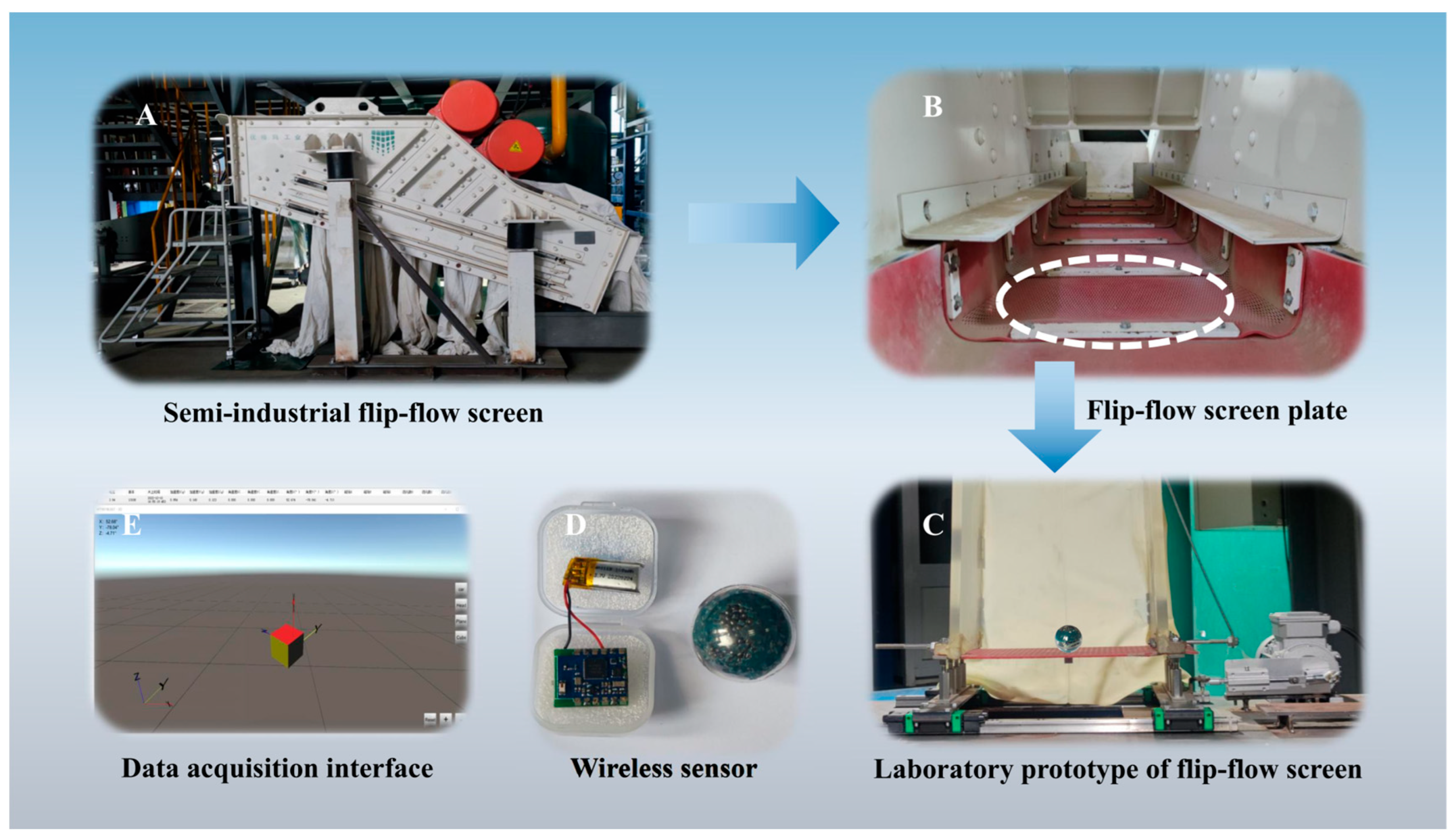
As shown in Figure 1, the experiment includes an impact experiment system and a semi-industrial flip-flow screen. The semi-industrial flip-flow screen was shown in Figure 1A. The screen is 1.8 m long and 0.6 m wide. Driven by the motor, the relative motion between the floating and fixed frames produces a displacement excitation of the screen plate. As shown in Figure 1B, the screen plate was composed of six flexible screen plates in succession. To explore the process of particle collision with the screen plate, a laboratory prototype screen consisting of a single section of the screen plate was built, and the displacement excitation of the screen plate was achieved through a motor, as shown in Figure 1C.
In this study, ilmenite was selected as the target screening material, to accurately replicate its dynamics, a tracer particle was developed using built-in inertial sensors to capture the mechanical and kinematic data. The tracer particle was mainly composed of an attitude sensor, a shell, and an internal filler, as shown in Figure 1D. By configuring the mass of the internal filler, the average density of the tracer particle was set to 4.5 g/cm3, which is consistent with the density of the ilmenite materials represented in this study. The integrated chip within the tracer particle utilized a nine-axis inertial measurement unit (IMU). This unit consists of a built-in 13-bit high-resolution triaxial accelerometer capable of measuring ±16 g with an accuracy of 0.0039 mg, a triaxial gyroscope equipped with a 16-bit analog-to-digital converter for measuring angular velocities of ±2000°/s at a sensitivity of 14.375 LSB/°/s, and a triaxial magnetometer for measuring magnetic field strengths of ±8 G with a 0.1° accuracy. During the data acquisition process, raw signals from the high-resolution accelerometer and gyroscope were first pre-processed to eliminate high-frequency noise. Numerical integration was then performed using the Trapezoidal rule within a synchronized program loop. To mitigate integration drift and error accumulation, an Extended Kalman Filter (EKF) fusion algorithm was adopted for real-time dynamic adjustment and compensation of sensor errors. Furthermore, the quaternion method was utilized to convert the body coordinate system to the reference coordinate system, ensuring the stability and accuracy of the kinematic data captured during the screening process.
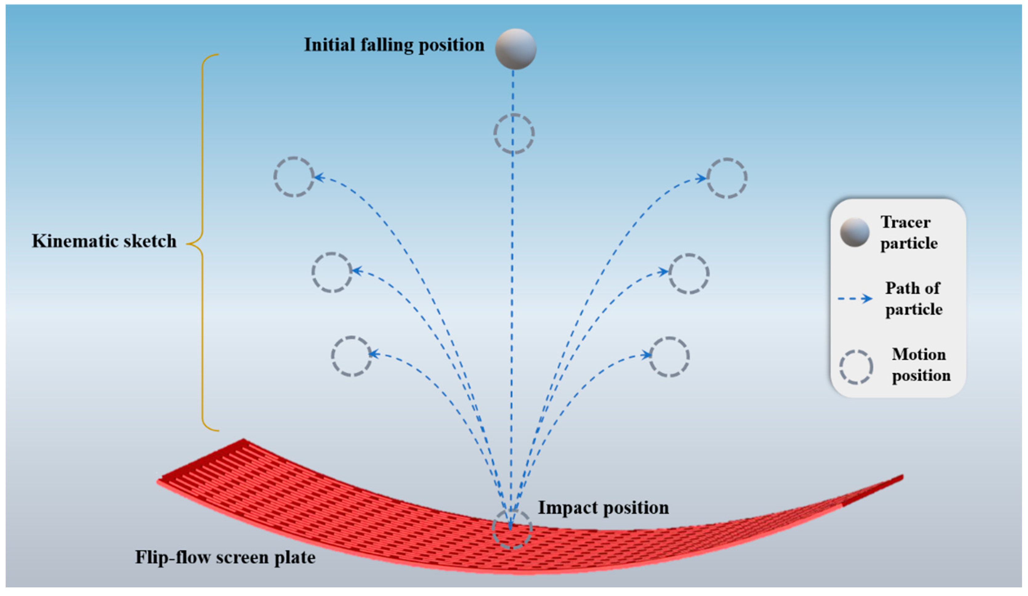
As shown in Figure 2, the tracer particle fell from above the screen plate; their initial position was 300 mm from the lowest position of the screen plate. The motor excitation frequency was set at 16.5 Hz, the amplitude of the screen plate was maintained at ±18 mm, and the tension of the screen plate is 3 mm. Due to the periodic movement of the screen plate, when the particle collided with it, its movement position was random. The mechanical behavior of the particle impacting the screen plate at different moving positions was also varied. When the screen plate center moved from the lowest position to the highest position, the time taken for particle to collide with the screen plate was also different. Based on this, this study used time data to reverse obtain the location of the screen plate center when particle hit the screen plate. Subsequently, the kinematic parameters of the particle impacting the screen plate at different moving positions were obtained.

3. Results

3.1. Mechanical Model of the Particle Impacted by Flip-Flow Screen Plate

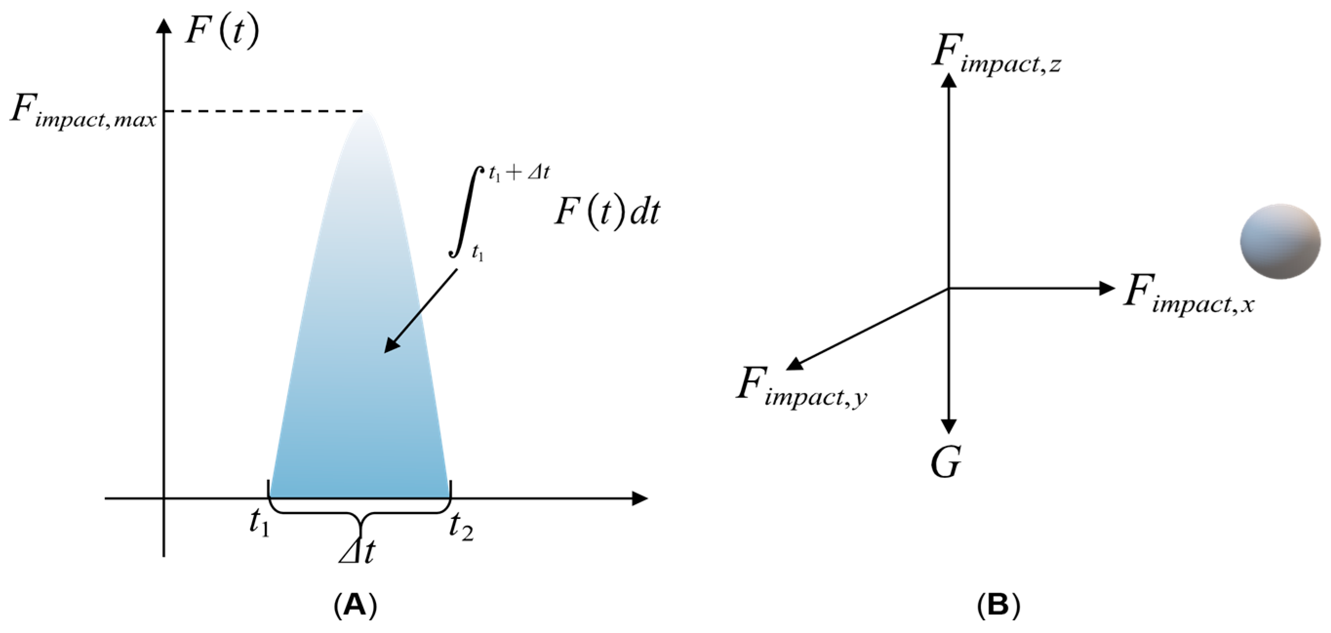
In the flip-flow screening process, the movement of the particle on the screen plate primarily considers the process of particle falling impact and throwing separation. As shown in Figure 3, the impact force of the screen plate on the particle acted in single-pulse mode, and its duration was short.
Before the collision, the impact force between the particle and screen plate was zero. However, at the moment of contact between the particle and screen plate, the screen plate produced an impact force on the particle. With the movement of the screen plate and the deepening of the collision, the particle began to rebound after the impact force reached its maximum. When the velocity between the particle and screen plate reached the same value with a difference in accelerations, they separate. The impact force of the particle on the screen plate was null at this moment. Therefore, taking the particle as the research object, the vector expression of the momentum theorem in the collision process between the particle and screen plate was established as follows:
m v 2 m v 1 = t 1 t 2 F i m p c t , i t d t + t 1 t 2 G d t
as shown in Table 1, where t1 is the initial moment of impact, s; t2 is the terminal moment of impact, s; t is the time history of the impact process, s; m is the mass of the particle, kg; v1, v2 are the velocity vectors before and after the collision, respectively; Fimpact,i is the impact force, N; and G is the gravity vector.
Owing to the large deflection and deformation of the flexible plate, its impact force on the particle was not completely along the normal direction of the screen plate. As shown on Figure 3B, the impact force of the screen plate on the particle was equivalent to the force along the x-, y-, and z-axes. Therefore, the scalar expressions of the three-directional momentum theorems were established as follows:
m v x 1 + m v x 2 = t 1 t 1 + Δ t F i m p a c t , x t d t m v y 1 + m v y 2 = t 1 t 1 + Δ t F i m p a c t , y t d t m v z 1 + m v z 2 = t 1 t 1 + Δ t F i m p a c t , z t d t t 1 t 1 + Δ t m g d t
where Fimpact,x, Fimpact,y, Fimpact,z are the maximum impact force exerted on the particle by the screen plate in different directions, N; Fimpact,max is the absolute maximum impact force, N.
The screen plate collision with the particle is of an elastic–plastic nature. During the screening process, the collision recovery coefficient e is related to the particle size and screen plate material, and the calculation method of e as follows:
e = v 2 v 1 = d 3 k s
where d is the relative particle size, dimensionless; ks is the relative stiffness of the screen surface, dimensionless.
As the impact force of the screen plate on the particle varied during collision, the average impact force was used to represent the impact force of the entire process. Furthermore, it was assumed that the average impact force was times the maximum impact force, as follows:
t 1 t 1 + Δ t F i m p a c t , i t d t = F ¯ i m p a c t , i Δ t
F ¯ i m p a c t , i = k e n , i F m a x i , i
Substituting Equations (3)–(5) into Equation (2), we obtained:
m v x 2 1 + e 1 = F i m a x , x k e n , x Δ t m v y 2 1 + e 1 = F i m a x , y k e n , y Δ t m v z 1 1 + e 1 = F i m a x , z k e n , z Δ t m g Δ t
The simplified results were:
F i m a x , x = m v x 2 k s + d 3 d 3 k e n , x Δ t F i m a x , y = m v y 2 k s + d 3 d 3 k e n , y Δ t F i m a x , z = m v z 2 k s + d 3 d 3 k e n , x Δ t + m g k e n , x
As the critical condition for the collision and separation of the particle and screen plates was that the relative velocity of these two was null, the accelerations of the two were inconsistent. Therefore, the final velocity vi2 of the collision separation can be obtained from the motion equation of the screen plate. Yang et al. proposed that for a screen plate with the same material property, the impact time history Δt of the particle mainly depends on the falling height of the particle h1, the upcast height of the particle h2, and the thickness of the screen plate l [35]:
Δ t = f h 1 , h 2 , l
It can be seen from Equations (7) and (8) that the impact force along the z-axis direction was significantly greater than that along the other two directions, indicating that the normal direction dominated the impact force of the screen plate on the particle. At the same time, the impact force of the screen plate on the particle depended on the particle mass, screen plate movement, screen plate thickness, screen plate stiffness, and other parameters. The parameters of particle mass, screen plate thickness, and stiffness were determined, but the motion of the screen plate was uncertain. Therefore, it was necessary to further explore the impact characteristics of the screen plate on the particle at different moving positions of the screen plate.

3.2. Kinematic Characteristics of the Particle Impacted by Flip-Flow Screen Plate

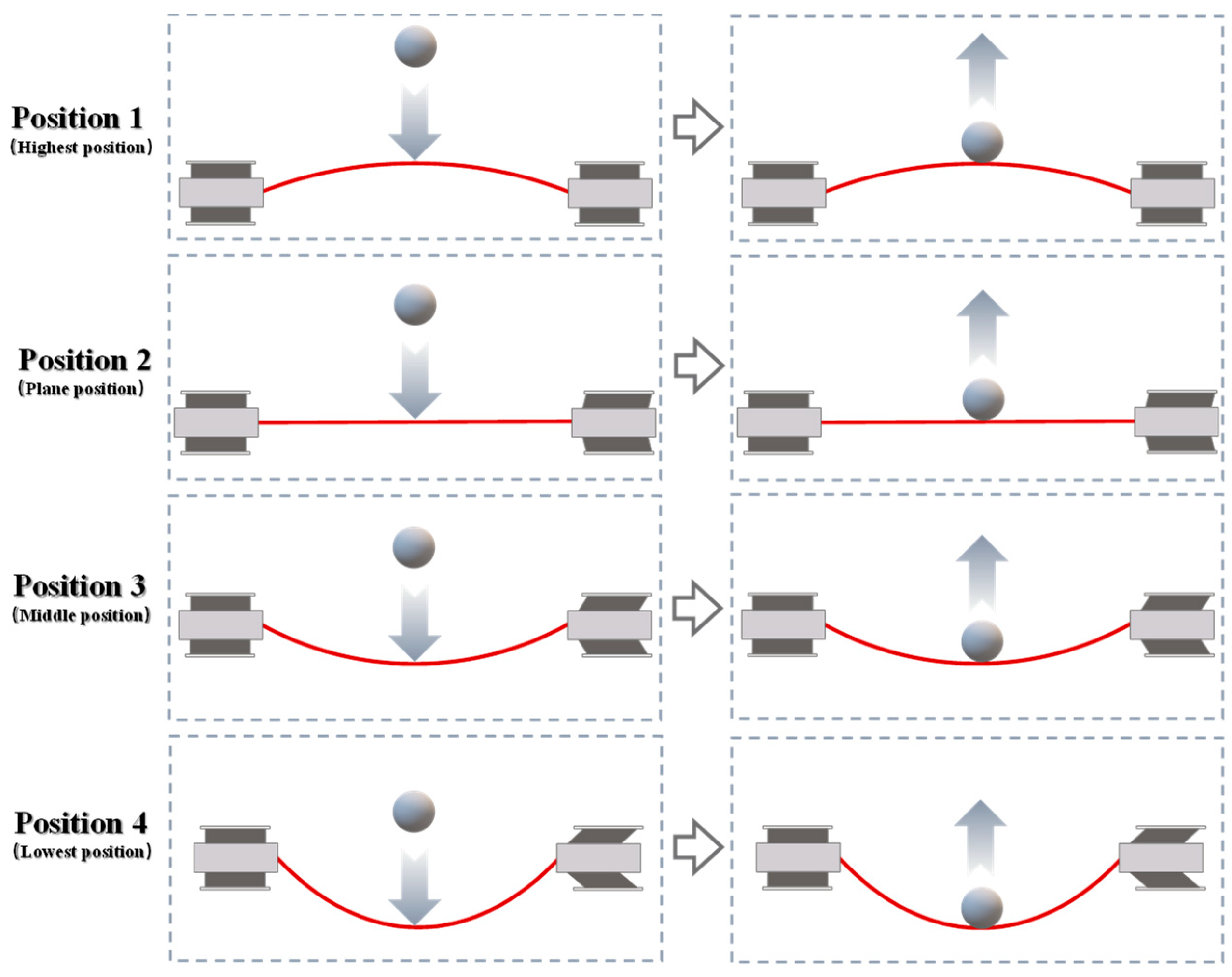
The movement of the flip-flow screen plate was periodic. To facilitate the investigation of the kinematic characteristics of the particle during collision, four representative screen plate movement positions were selected, as shown in Figure 4.
Position 1 indicates that the particle collided with the screen plate when it moved to the highest position. Position 2 indicates that the particle collided with the screen plate when the screen plate moved to the plane position. Position 3 indicates that when the screen plate moved to the intermediate positions, the particle collided with the screen plate. Finally, position 4 indicates that the particle collided with the screen plate when the screen plate moved to the lowest positions. The left side of Figure 4 is the diagram of particle motion before collision, and the right side of Figure 4 is a diagram of particle motion after collision.
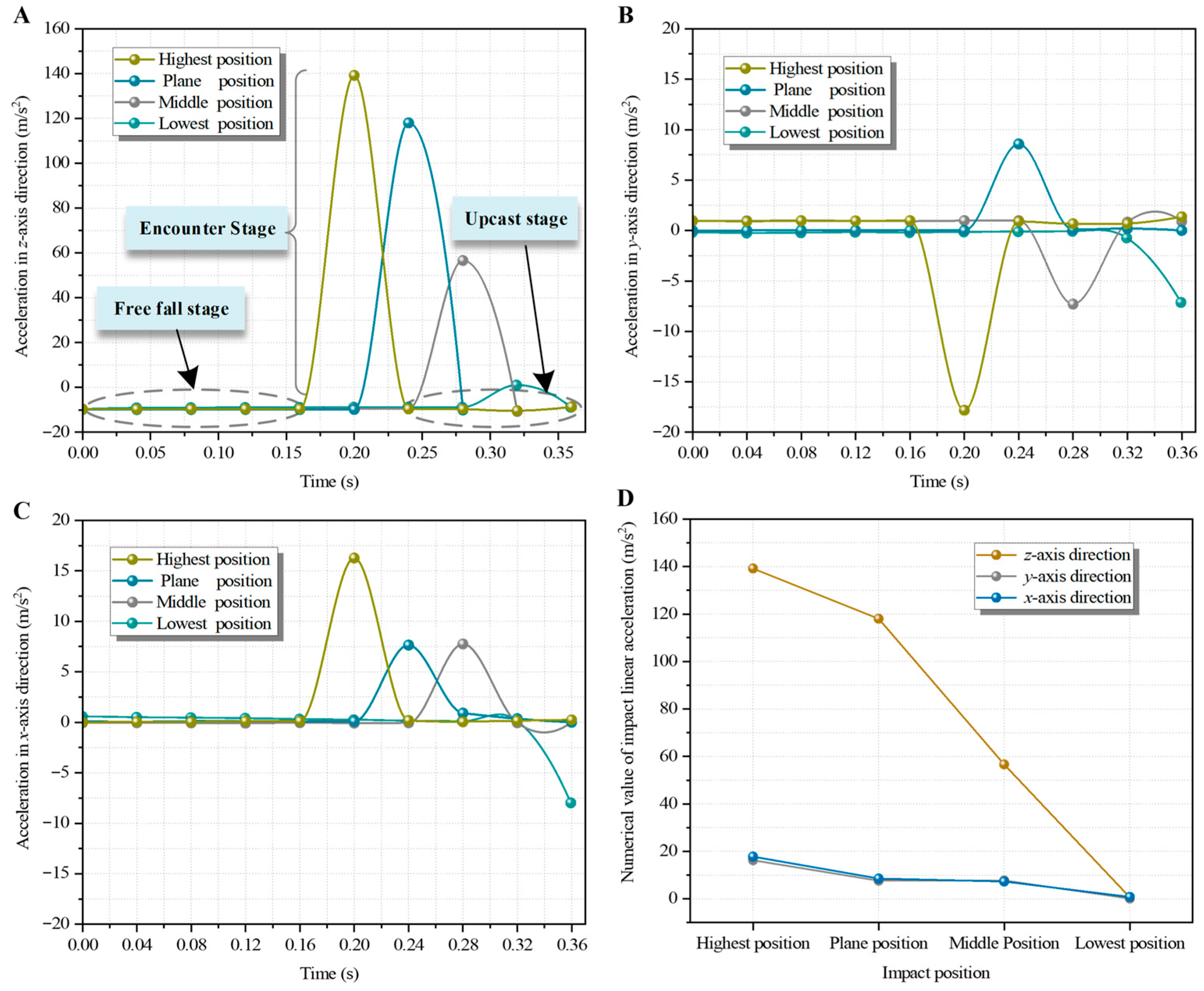
First, the Cartesian coordinate system was established, in which the z-axis was along the vertical direction (i.e., the direction of gravitational acceleration); the y-axis was along the screen plate displacement excitation direction, and the x-axis was along the horizontal direction perpendicular to the screen plate displacement excitation. Figure 5A–C show the linear acceleration changes along the z-axis, y-axis, and x-axis, respectively.
As shown in Figure 5A, taking Position 1 as an example, the particle movement process can be divided into the free-falling, collision, and throwing stages. In the free-falling and throwing stages, the linear acceleration of the particle was consistent with the gravitational acceleration. In the collision phase, the linear acceleration of the particle first increased and then decreased. When t was 0.20 s, the maximum value of linear acceleration was 139.18 m/s2. At this time, the particle completely collided with the screen plate, and this peak value is defined as the impact acceleration.
Similarly, the components of Figure 5A–C in each position and direction include the above three stages. At the same time, in Figure 5B, the direction of linear acceleration along the y-axis at each position was inconsistent. This inconsistency was due to the flip motion of the screen plate along its excitation direction. In this context, the particle could not maintain balance in this direction, leading to uncertainty in the direction of the impact acceleration.
As shown in Figure 5D, at each position, the linear acceleration along the z-axis was greater than that in the other two directions, indicating that the z-direction was the dominant direction of the linear acceleration. This phenomenon is attributed to the synergistic effect of gravitational potential energy conversion and the normal impact direction of the flexible plate. During the flip-flow screening process, the tensioned deformation of the screen plate concentrates the majority of the elastic restoring force in the normal direction (z-axis), which is significantly more intense than the tangential frictional forces along the x-axis or y-axis. This mechanism ensures that particles gain maximum vertical lift, which is essential for effective material loosening and stratification. From the highest to the lowest position of the screen plate movement, the impact acceleration along the z-axis gradually decreased. When the screen plate moved to the lowest position, the linear acceleration values in the x, y, and z directions were close to zero, which indicated that at this position, the screen plate was in a relaxed state and the force of the screen plate on the particle was small.
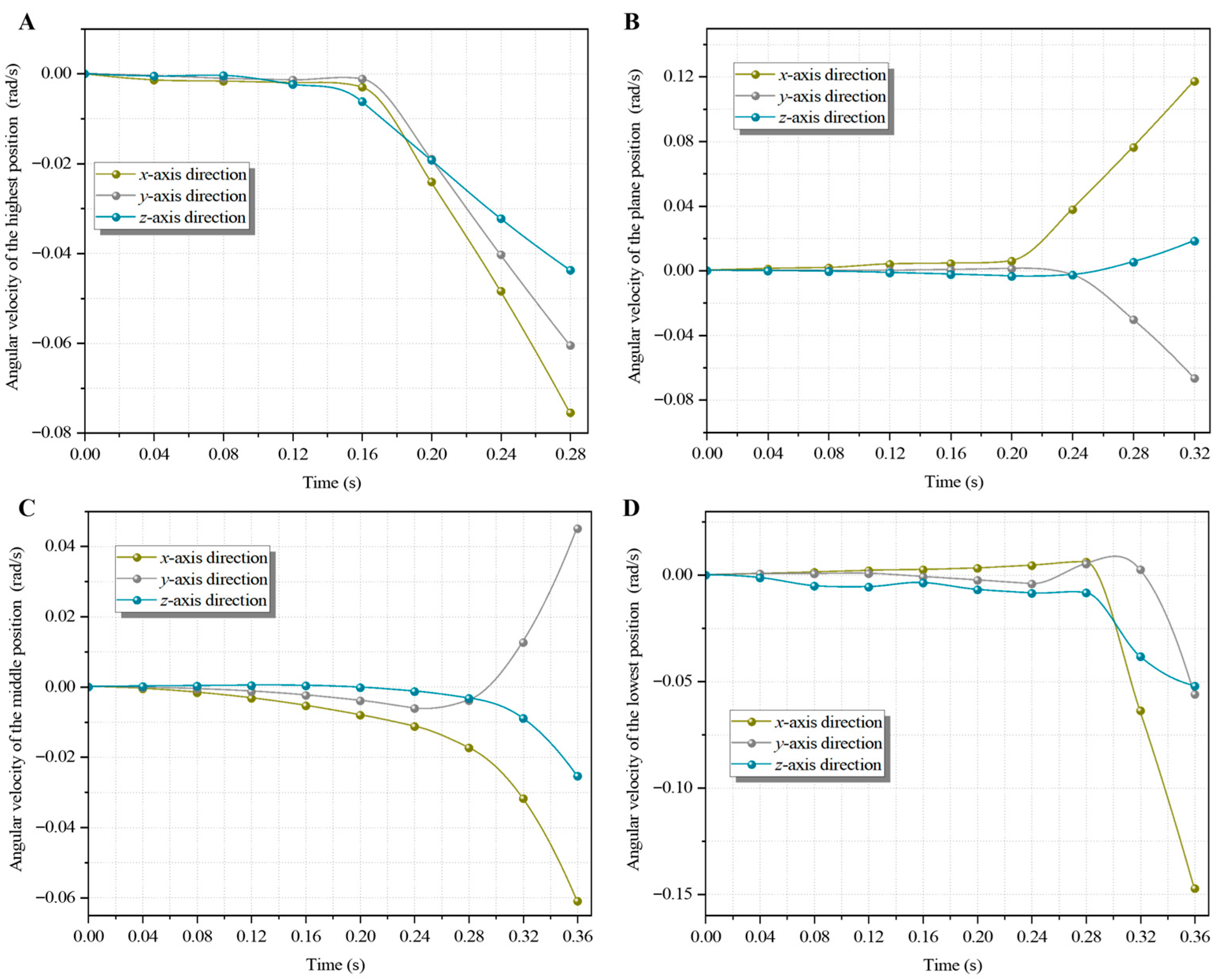
As shown in Figure 6, the angular velocity changed when the particle impacted the screen plate at different moving positions. The positive and negative components along each axis represent the positive and negative directions, respectively. Figure 6A–D represent the change in angular velocity with time when the screen plate moved to the highest, plane, middle, and lowest positions, respectively. It was found that in the free-falling stage, the particle rotated only in a small range or did not rotate. When the particle collided with the screen plate, they rotated rapidly, but their rotation was inconsistent when they collided with different positions of the screen plate. The above figure shows that the particle collided with the screen plate at different moving positions and that the change in amplitude of the components in the x-axis direction was greater than that in the other two directions. When the collision occurred at the lowest position, the change in the amplitude of the component in the x-axis direction was the most evident. This shows that when the particle collided with the screen plate, the force exerted on the particle by the screen plate mainly came from the normal direction of the screen plate, which also verified the conclusion of Section 3.1.

3.3. Kinetic Energy Variation of the Particle Impacted by Flip-Flow Screen Plate

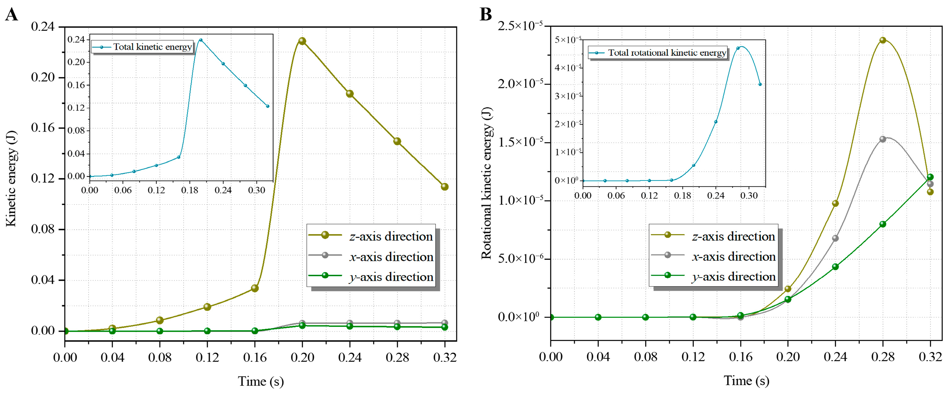
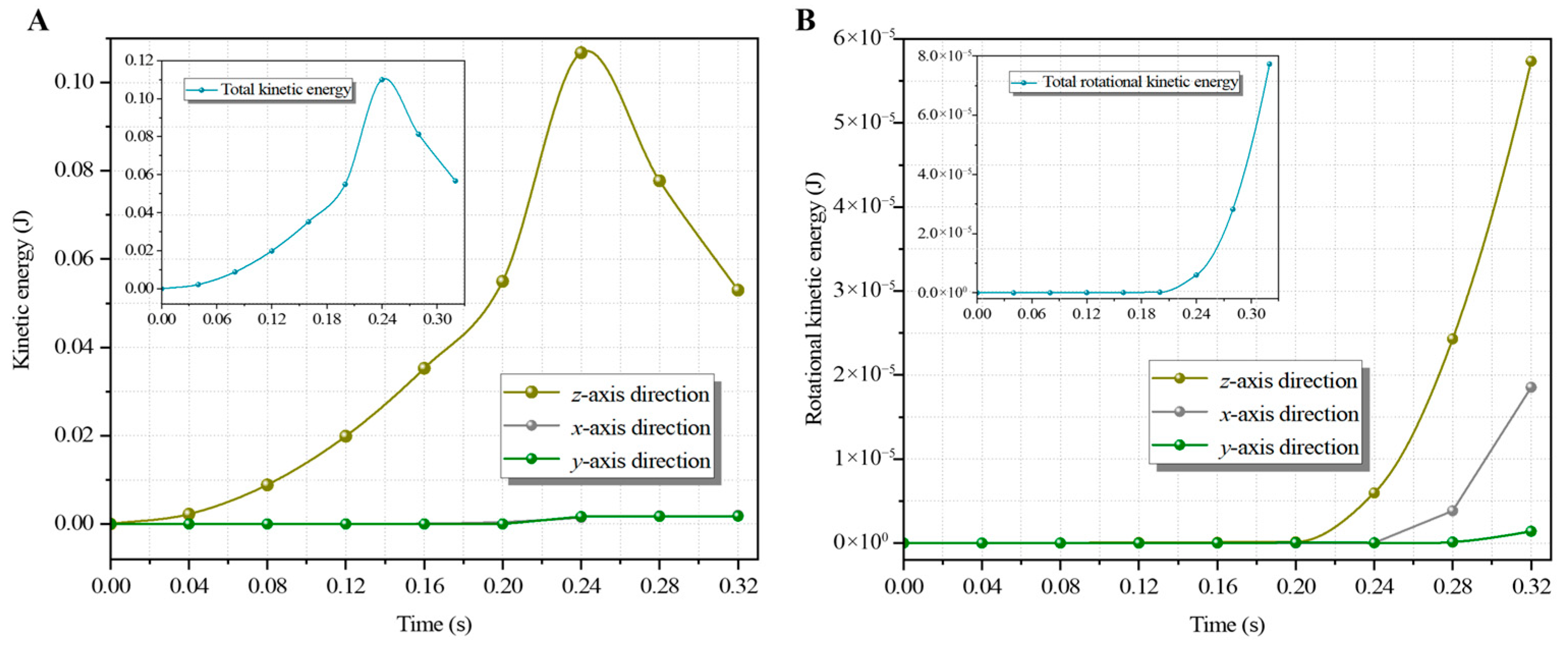
As shown in Section 3.1, the translational and rotational kinetic energies of the particle also change during the collision between the particle and the flip-flow screen plate. Therefore, the change in translational kinetic energy and rotational kinetic energy can be obtained by the integral conversion of the collected acceleration signal, as shown in Figure 7, Figure 8, Figure 9 and Figure 10.
As shown in Figure 7A, in the first 0.16 s, the translational kinetic energy of the particle along the z-axis increased uniformly, and the translational kinetic energy along the y-axis and x-axis remained at zero; this is the free-falling stage. At the collision stage between the particle and screen plate, from 0.16 s to 0.20 s, the translational kinetic energy in the z-axis direction rapidly increased to 0.229 J. After 0.20 s, at the throwing stage after collision separation, the translational kinetic energy in this direction decreases uniformly. In Figure 7B, the rotational kinetic energy of the particle in all directions stays unchanged in the first 0.16 s. Between 0.16 s and 0.20 s, the particle collided with the screen plate, and the kinetic energy of rotation in all directions increased. After 0.20 s, the rotational kinetic energy along the z-axis and x-axis decreased, and the rotational kinetic energy along the y-axis continued to increase. These results for the rotational kinetic energy were due to the change in the direction of the screen plate, excited by displacement (i.e., y-axis direction), when it reaches its highest position. While colliding with the screen plate in this state, the particle becomes unstable in the y-axis direction, resulting in a continued increase in the rotational kinetic energy in this direction.
Similarly, in Figure 8A, for the first 0.20 s (free-falling stage of the particle), the translational kinetic energy along the z-axis increased uniformly. In contrast, the kinetic energy along the x-and y-axes remained unchanged. At 0.20 s, the kinetic energy along the z-axis rapidly increased to 0.107 J and then gradually decreased. In Figure 8B, the rotational kinetic energy of the particle in all directions is maintained at zero in the first 0.20 s. However, after 0.20 s, the rotational kinetic energy along each axis gradually increased, and the change in amplitude along the z-axis was the largest. This increase is due to the collision of the particle with the screen plate along the z-axis, resulting in a force acting on the particle in this direction.
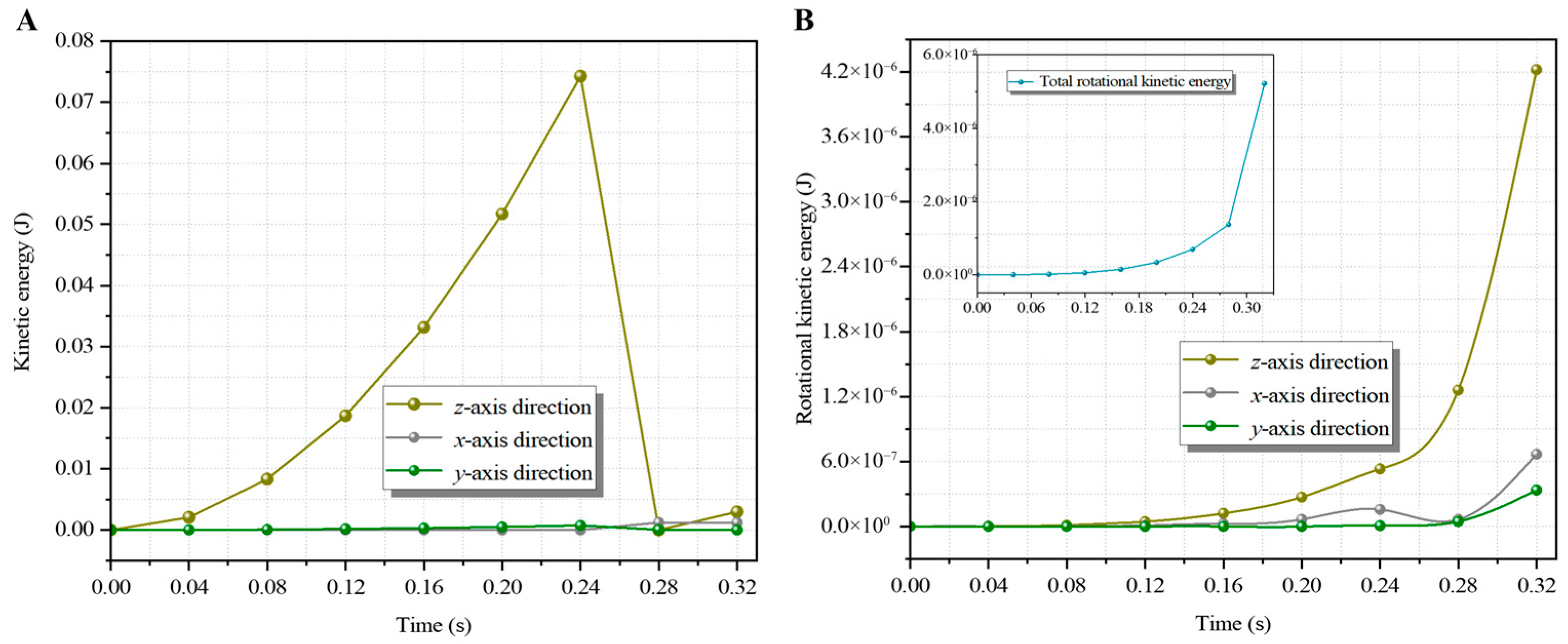
As shown in Figure 9A, before the particle collided with the screen plate at its middle position, it was in the free-falling stage. The translational kinetic energy components along the x-and y-axes were null, and the translational kinetic energy along the z-axis gradually increased. In the collision stage between the particle and the screen plate, the translational kinetic energy of the particle along the z-axis decreased rapidly, approaching zero. In Figure 9B, in the collision phase, the rotational kinetic energy in the three directions gradually increased. It had the largest change along the z-axis, indicating that the particle mainly rotated in this direction.
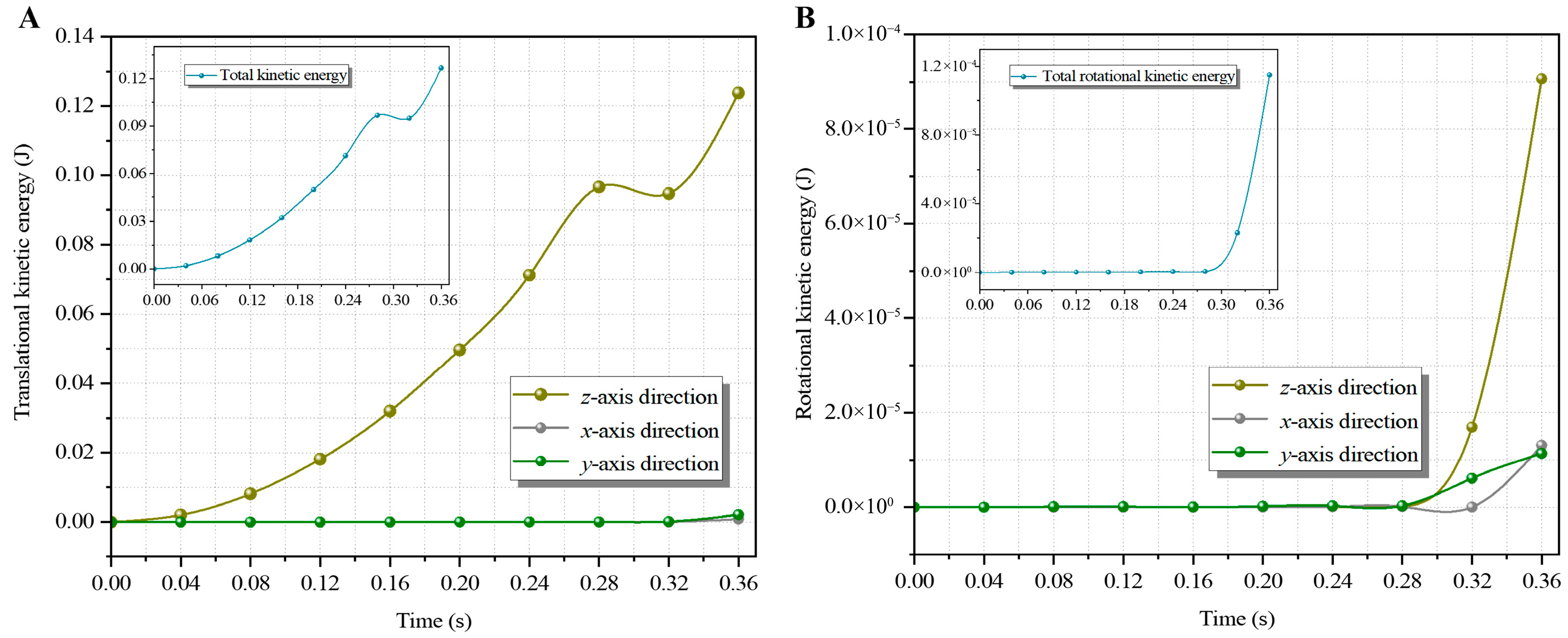
In Figure 10A, when the screen plate moved to the lowest position of the particle collision domain, the translational kinetic energy components along the x-and y-axes were null. The translational kinetic energy component along the z-axis initially increased gradually. However, at the moment of collision with the screen plate, the kinetic energy of the particle decreased momentarily and then continued to increase after the collision and separation. At the same time, the change in kinetic energy in this direction was consistent with the general trend in translational kinetic energy. In Figure 10B, the rotational kinetic energy of the particle remained unchanged during the free-fall phase and increased gradually in the collision and separation stages. In addition, the translational and rotational kinetic energies along the z-axis were dominant. These results indicate that when the particle collided with the lowest moving position of the screen plate, the change in the kinetic energy of the particle was maintained in the vertical direction and that the force of the screen plate on the particle was primarily from this direction.
In summary, the particle collided with the screen plate at different moving positions. In the free-falling stage, the translational kinetic energy of the particle increased uniformly, whereas the rotational kinetic energy remained unchanged. In the collision phase, the translational and rotational kinetic energies of the particle increased rapidly, and both components along the z-axis were dominant. Finally, in the upcast stage, the rotational kinetic energy of the particle continued to increase, and the translational kinetic energy resumed increasing after a slight decrease. At the same time, through comparison, at Position 1 (highest position), the plate reaches its state of maximum tension and peak instantaneous velocity, resulting in maximum instantaneous stiffness and the most efficient energy transfer to the ilmenite particle. Conversely, at the lowest position, the relaxed state of the membrane acts as a buffer, dissipating energy through damping and leading to minimal acceleration and kinetic energy gain. These results demonstrate that optimizing the excitation frequency to synchronize collisions with the periodic deformation of the screen plate, which enables particles to attain higher accelerations to overcome liquid bridge forces and adhesion between wet fine-grained materials, represents an effective measure to facilitate rapid loosening and stratification, ultimately enhancing screening efficiency.

4. Conclusions

In order to explore the impact mechanical behavior and kinematic characteristics of the particle and flip-flow screen plate collision, the following conclusions were obtained based on a spherical inertial measurement device and a semi-industrial flip-flow screen system.
  • The impact mechanics model of the screen plate on the particle was established as follows:
    F i m a x , x = m v x 2 k s + d 3 d 3 k e n , x Δ t F i m a x , y = m v y 2 k s + d 3 d 3 k e n , y Δ t F i m a x , z = m v z 2 k s + d 3 d 3 k e n , x Δ t + m g k e n , x
    The impact force of the screen plate on a particle depends, among other parameters, on the particle mass and the screen plate’s movement, thickness, and stiffness.
  • The linear acceleration amplitude along the z-axis gradually decreased from the highest to the lowest position of the screen plate movement. The maximum value of linear acceleration was 139.18 m/s2, at which position the particle completely collided with the screen plate, and the linear acceleration was the impact acceleration. When the particle collides with the screen plate at different moving positions, the angular velocity of acceleration along the displacement excitation direction changes significantly.
  • In the collision phase, the translational and rotational kinetic energies of the particle increase rapidly, and the vertical component dominates. The translational and rotational kinetic energies of the particle at the highest position of the screen plate were greater than those at the other positions. At this position, the translational kinetic energy of particles in the z-axis direction is 0.229 J, and the rotational kinetic energy is 2.26 × 10⁻⁵ J.

Author Contributions

Conceptualization, W.W. and X.H.; methodology, W.W. and J.P.; software, X.H.; validation, J.P. and W.S.; formal analysis, W.W.; investigation, W.S.; resources, W.S. and X.Y.; data curation, J.P.; writing—original draft preparation, W.W. and X.H.; writing—review and editing, W.W.; visualization, X.H. and J.P.; supervision, W.S. and X.Y.; project administration, W.W., W.S. and X.Y.; funding acquisition, W.W. All authors have read and agreed to the published version of the manuscript.

Funding

This research was funded by Open Foundation of State Key Laboratory of Mineral Processing (Grant No. BGRIMM-KJSKL-2024-20).

Data Availability Statement

The original contributions presented in the study are included in the article, further inquiries can be directed to the corresponding authors.

Conflicts of Interest

Authors Weinan Wang and Xiaolu Ye were employed by the State Key Laboratory of Mineral Processing Science and Technology, BGRIMM Technology Group. The remaining authors declare that the research was conducted in the absence of any commercial or financial relationships that could be construed as a potential conflict of interest. The authors declare that this study received funding from the Open Foundation of State Key Laboratory of Mineral Processing. The funder was not involved in the study design, collection, analysis, interpretation of data, the writing of this article, or the decision to submit it for publication.

References

  1. Ku, J.; Shi, X.; Wang, Q.; Lin, H.; Shang, H.; Shen, Z. Efficient exploitation of lepidolite resources: A review on beneficiation techniques, extraction methods, and synergistic optimization. Separations 2025, 12, 130. [Google Scholar] [CrossRef] [Scilit]
  2. Darius, M.; Harald, K.E. Coupled dem-sph simulations of wet continuous screening. Adv. Powder Technol. 2019, 30, 2997–3009. [Google Scholar] [CrossRef] [Scilit]
  3. Hou, X.; Mao, P.; Zhang, S.; Pan, J.; Wang, C.; Zhao, Y.; Wang, W.; Duan, C. Study on impact mechanical characteristics and screening performance of fine coal during flip-flow screening process. Int. J. Coal Prep. Util. 2024, 28, 648–657. [Google Scholar] [CrossRef] [Scilit]
  4. Arifuzzaman, S.M.; Dong, K.; Yu, A. Process model of vibrating screen based on dem and physics-informed machine learning. Powder Technol. 2022, 410, 117869. [Google Scholar] [CrossRef] [Scilit]
  5. Fan, M.; Tao, D.; Zhao, Y.; Honaker, R. Effect of nanobubbles on the flotation of different sizes of coal particle. Miner. Metall. Process. 2013, 30, 157–161. [Google Scholar] [CrossRef] [Scilit]
  6. Duan, C.; Yuan, J.; Pan, M.; Huang, T.; Jiang, H.; Zhao, Y.; Qiao, J.; Wang, W.; Yu, S.; Lu, J. Variable elliptical vibrating screen: Particles kinematics and industrial application. Int. J. Min. Sci. Technol. 2021, 31, 1013–1022. [Google Scholar] [CrossRef] [Scilit]
  7. Xu, N.; Huang, Z.; Guan, T.; Feng, X.; Guo, H.; Liu, J.; Song, X.; Shi, W.; Pan, M. Experimental study and industrial application of rigid–flexible coupling screening for difficult-to-screen sticky and moist gold ores. Separations 2026, 13, 6. [Google Scholar] [CrossRef] [Scilit]
  8. Li, S.; Liu, C.; Liu, H.; He, D. Prediction and optimization of screening performance of three-deck vibrating screen based on surrogate model. Int. J. Coal Prep. Util. 2024, 44, 626–645. [Google Scholar] [CrossRef] [Scilit]
  9. He, D.; Liu, C. Study on screening mechanism and numerical simulation for crashed concrete particles by using DEM. Separations 2022, 9, 153. [Google Scholar] [CrossRef] [Scilit]
  10. Hou, D.; Zhao, Q.; Cui, B.; Wei, D.; Song, Z.; Feng, Y. Geometrical configuration of hydrocyclone for improving the separation performance. Adv. Powder Technol. 2022, 33, 103419. [Google Scholar] [CrossRef] [Scilit]
  11. Zhao, Q.; Hou, D.; Cui, B.; Wei, D.; Song, T.; Feng, Y. Development of an integrated multichannel inlet for improved particle classification in hydrocyclones. Adv. Powder Technol. 2021, 32, 4546–4561. [Google Scholar] [CrossRef] [Scilit]
  12. Ogunmodimu, O.; Govender, I.; Mainza, A.N.; Franzidis, J. Development of a mechanistic model of granular flow on vibrating screens. Miner. Eng. 2021, 163, 106771. [Google Scholar] [CrossRef] [Scilit]
  13. He, D.; Liu, C.; Li, S. The nonlinear dynamic behavior of a particle on a vibrating screen based on the elastoplastic contact model. Separations 2022, 9, 216. [Google Scholar] [CrossRef] [Scilit]
  14. Yu, C.; Pu, K.; Geng, R.; Qiao, D.; Lin, D.; Xu, N.; Wang, X.; Li, J.; Gong, S.; Zhou, Q. Comparison of flip-flow screen and circular vibrating screen vibratory sieving processes for sticky fine particles. Miner. Eng. 2022, 187, 107791. [Google Scholar] [CrossRef] [Scilit]
  15. Yu, C.; Wang, X.; Pang, K.; Zhao, G.; Sun, W. Dynamic characteristics of a vibrating flip-flow screen and analysis for screening 3 mm iron ore. Shock. Vib. 2020, 2020, 1–12. [Google Scholar] [CrossRef] [Scilit]
  16. Jiang, H.; Yu, S.; Pan, M.; Duan, C.; Zhao, Y.; Zhou, Z.; Liu, C.; Wu, J.; Song, B. Effect of excitation parameters on motion characteristics and classification performance of rigid-flexible coupled elastic screen surface for moist coal. Adv. Powder Technol. 2020, 31, 196–1208. [Google Scholar] [CrossRef] [Scilit]
  17. Cao, P.; Tang, J.; Xiong, X.; Niu, L. Synchronous control strategy of double excitation motors inertial flip-flow screen. ISA Trans. 2022, 129, 581–593. [Google Scholar] [CrossRef] [Scilit]
  18. Gong, S.; Oberst, S.; Wang, X. Dynamic analysis of vibrating flip-flow screens equipped with support and shear rubber springs. J. Phys. Conf. Ser. 2019, 1264, 12061. [Google Scholar] [CrossRef] [Scilit]
  19. Lin, D.; Xu, N.; Yu, C.; Geng, R.; Wang, X.; Gong, S. Nonlinear model of vibrating flip-flow screens that considers the effects of screen panels. IEEE Access 2022, 10, 34246–34259. [Google Scholar] [CrossRef] [Scilit]
  20. Tang, J.; Niu, L.; Xiong, X.; Jie, S. Viscoelasticity of rubber springs affects vibration characteristics of a flip-flow screen with the high g value. IEEE Access 2020, 8, 26950–26965. [Google Scholar] [CrossRef] [Scilit]
  21. Wu, B.; Zhang, X.; Niu, L.; Xiong, X.; Dong, Z.; Tang, J. Research on sieving performance of flip-flow screen using two-way particles-screen panels coupling strategy. IEEE Access 2019, 7, 124461–124473. [Google Scholar] [CrossRef] [Scilit]
  22. Xiong, X.; Niu, L.; Gu, Y.; Wang, Y. Vibration characteristics of an inclined flip-flow screen panel in banana flip-flow screens. J. Sound Vib. 2017, 411, 108–128. [Google Scholar] [CrossRef] [Scilit]
  23. Chen, B.; Yu, C.; Gong, S.; Wang, X. Dynamic characteristics of liwell flip-flow screen panel and particle movement. Chem. Eng. Sci. 2021, 245, 116853. [Google Scholar] [CrossRef] [Scilit]
  24. Li, H.; Liu, C.; Shen, L.; Zhao, L. Vibration characteristics of an industrial-scale flip-flow screen with crank-link structure and parameters optimization. Shock. Vib. 2021, 2021, 1–16. [Google Scholar] [CrossRef] [Scilit]
  25. Zhao, G.; Wang, X.; Lin, D.; Xu, N.; Yu, C.; Geng, R. Study of double-deck vibrating flip-flow screen based on dynamic stiffness characteristics of shear springs. Minerals 2021, 11, 928. [Google Scholar] [CrossRef] [Scilit]
  26. Gong, S.; Oberst, S.; Wang, X. An experimentally validated rubber shear spring model for vibrating flip-flow screens. Mech. Syst. Signal Process. 2020, 139, 106619. [Google Scholar] [CrossRef] [Scilit]
  27. Wu, J.; Liu, C.; Jiang, H.; Zhang, B. A vibration-test-based calculation method of screening material mass of a mining crank-link type flip-flow screen. Energy Sources Part A Recovery Util. Environ. Eff. 2024, 46, 9655–9675. [Google Scholar] [CrossRef] [Scilit]
  28. Chen, Z.; Huang, L.; Jiang, H.; Zhao, Y.; Liu, C.; Duan, C.; Zhang, B.; Yang, G.; Chai, J.; Ban, H.; et al. Application of screening using a flip-flow screen and shallow groove dense-medium separation in a steam coal preparation plant. Int. J. Coal Prep. Util. 2022, 42, 2438–2451. [Google Scholar] [CrossRef] [Scilit]
  29. Wang, W.; Pan, M.; Duan, C.; Jiang, H.; Zhao, Y.; Lu, H. Dry deep screening of spodumene and its mineral processing technology. Miner. Eng. 2022, 179, 107445. [Google Scholar] [CrossRef] [Scilit]
  30. Akbari, H.; Ackah, L.; Mohanty, M. Performance optimization of a new air table and flip-flow screen for fine particle dry separation. Int. J. Coal Prep. Util. 2020, 40, 581–603. [Google Scholar] [CrossRef] [Scilit]
  31. Wang, W.; Hou, X.; Duan, C.; Mao, P.; Jiang, H.; Qiao, J.; Pan, M.; Fan, X.; Zhao, Y.; Lu, H. Dynamic model of the flip-flow screen-penetration process and influence mechanism of multiple parameters. Adv. Powder Technol. 2022, 33, 103814. [Google Scholar] [CrossRef] [Scilit]
  32. Wang, W.; Lu, J.; Wang, C.; Yuan, J.; Hou, X.; Pan, M.; Jiang, H.; Qiao, J.; Duan, C.; Dombon, E.; et al. Study on screening probability model and particle-size effect of flip-flow screen. Adv. Powder Technol. 2022, 33, 103668. [Google Scholar] [CrossRef] [Scilit]
  33. Zhang, S.; Wang, W.; Zhao, W.; Hou, X.; Mao, P.; Pan, J.; Duan, C. Kinetic screening process model under the gradual change of screen plate opening rate and its influence on the screening effect. Chem. Eng. Sci. 2026, 320, 122474. [Google Scholar] [CrossRef] [Scilit]
  34. Elskamp, F.; Kruggel-Emden, H. Review and benchmarking of process models for batch screening based on discrete element simulations. Adv. Powder Technol. 2015, 26, 679–697. [Google Scholar] [CrossRef] [Scilit]
  35. Yang, Q.; Guan, B. Test and research on calculating method of falling stone impulsive force. J. China Railw. Soc. 1996, 18, 101–106. [Google Scholar]
Figure 1. Impact experiment system of flip-flow plates based on a spherical inertial measurement device and a semi-industrial flip-flow screen system: (A) Semi-industrial flip-flow screen; (B) Flip-flow screen plate; (C) Laboratory prototype of flip-flow screen; (D) Wireless sensor; (E) Date acquisition interface.
Separations 13 00113 g001
Figure 2. Motion diagram of the particle colliding with a single screen plate during flip-flow screening.
Separations 13 00113 g002
Figure 3. (A) Schematic diagram of the screen plate impact force on the particle; (B) force analysis of the particle.
Separations 13 00113 g003
Figure 4. Schematic diagram of the particle colliding with the screen plate at different moving positions.
Separations 13 00113 g004
Figure 5. (A) Linear acceleration of the particle along the z-axis; (B) Linear acceleration of the particle along the y-axis; (C) Linear acceleration of the particle along the x-axis; (D) Comparison of linear accelerations of the particle at different screen positions.
Separations 13 00113 g005
Figure 6. (A) Angular velocity at the highest position of the screen plate; (B) Angular velocity at the plane position of the screen plate; (C) Angular velocity at the middle position of the screen plate; (D) Angular velocity at the lowest position of the screen plate.
Separations 13 00113 g006
Figure 7. (A) Particle translational kinetic energy change during screen plate impact (highest position); (B) Particle rotational kinetic energy change during screen plate impact (highest position).
Separations 13 00113 g007
Figure 8. (A) Particle translational kinetic energy change during screen plate impact (plane position); (B) Particle rotational kinetic energy change during screen plate impact (plane position).
Separations 13 00113 g008
Figure 9. (A) Particle translational kinetic energy change during screen plate impact (middle position); (B) Particle rotational kinetic energy change during screen plate impact (middle position).
Separations 13 00113 g009
Figure 10. (A) Particle translational kinetic energy change during screen plate impact (lowest position); (B) Particle rotational kinetic energy change during screen plate impact (lowest position).
Separations 13 00113 g010
Table 1. List of acronyms and symbols.
ParameterDefinitionUnitParameterDefinitionUnit
F(t)Function of impact forceNvi1Initial linear velocity of the particle at impactm/s
F impact , i Maximum impact forceNvi2Linear velocity of the particle during separationm/s
F - impact , i Average impact forceNeCollision recovery coefficient-
iDirection of coordinate axis-mMass of the particlekg
tTime of particle movementsdDiameter of the particlem
t1The moment of collisionsksStiffness of screen platem
t2The moment of separationsken,iAmplification factor of impact force-
t Time history of impact processsh1Height of the particle fallingm
GGravityNh2Throwing height of particlem
gGravitational accelerationm/s2lThickness of screen platem
Disclaimer/Publisher’s Note: The statements, opinions and data contained in all publications are solely those of the individual author(s) and contributor(s) and not of MDPI and/or the editor(s). MDPI and/or the editor(s) disclaim responsibility for any injury to people or property resulting from any ideas, methods, instructions or products referred to in the content.