Article

A Laser Shock-Based Disassembly Process for Adhesively Bonded Ti/CFRP Parts

1
Laboratory of Technology & Strength of Materials (LTSM), Department of Mechanical Engineering & Aeronautics, University of Patras, 26504 Patras, Greece
2
PIMM, UMR8006 ENSAM, CNRS, CNAM, 151 bd de l’Hôpital, 75013 Paris, France
*
Author to whom correspondence should be addressed.
Processes 2023, 11(2), 506; https://doi.org/10.3390/pr11020506
Submission received: 22 December 2022 / Revised: 31 January 2023 / Accepted: 3 February 2023 / Published: 7 February 2023
(This article belongs to the Special Issue Design of Adhesive Bonded Joints)

Abstract

:
The application of adhesively bonded joints in aerospace structural parts has increased significantly in recent years and the general advantages of their use are well-documented. One of the disadvantages of adhesive bonding is the relevant permanence, when compared to traditional mechanical fastening. End-of-life processes generally require the separation of the adherents for repair or recycling, and usually to achieve this, they combine large mechanical forces with a high temperature, thus damaging the adherents, while consuming large amounts of energy. In this work, a novel disassembly technique based on laser-induced shock waves is proposed for the disassembly of multi-material adhesively bonded structures. The laser shock technique can generate high tensile stresses that are able to break a joint, while being localized enough to avoid damaging the involved adherents. The process is applied to specimens made from a 3D-woven CFRP core bonded to a thin Ti layer, which is a common assembly used in state-of-the-art aircraft fan blades. The experimental process has been progressively developed. First, a single-sided shot is applied, while the particle velocity is measured at the back face of the material. This method proves ineffective for damage creation and led to a symmetric laser configuration, so that the tensile stress can be controlled and focused on the bond line. The symmetric approach is proved capable of generating a debonding between the Ti and the CFRP and propagating it by moving the laser spot. Qualitative assessment of the damage that is created during the symmetric experimental process indicates that the laser shock technique can be used as a material separation method.

1. Introduction

Recent aircraft construction has replaced nearly 50% of metallic parts with composite materials, as their specific properties are essential for weight reduction. While the weight decrease is accompanied by reduced fuel consumption, the broad application of composites has raised some different environmental challenges. The biggest environmental impact is the increasing generation of large amounts of waste and landfill material as more structures reach their end-of-life (EoL) [1].
Advancements in recycling have made it possible to recover carbon and glass fibers from composite materials that have reached their EoL, using strategies like pyrolysis [2] or solvolysis [3]. Furthermore, other strategies have been proposed to utilize shredding of the composite to be used as a filler in bio-based resins, thus delaying their landfill deposition [4]. To employ such strategies with sufficient efficiency, it is important that the different materials are well-separated and sorted.
General aircraft EoL processes have been designed for material separation before component recycling. Separation strategies are chosen based on a cost–benefit analysis, with the extreme cases being systematic disassembly and shredding. Systematic disassembly is the process of separating and sorting all the components based on material composition. It is a labor-intensive process and yields the best material segregation. On the other end of the cost–benefit spectrum, shredding is the process of cutting pieces of the aircraft containing a multitude of materials, such as aluminum, titanium, composites, glass, etc. This process is concentrated on quantity over quality [5,6]. The two extremes are not usually desirable because of the excessive cost or the poor material quality, respectively. Intermediate strategies, on the other hand, use the mapping of the aircraft and specific combinations of shredding, cutting, and disassembly are utilized, according to material homogeneity, as illustrated in Figure 1.
Bonded metal, composite, and multi-material structures are a common design choice of state-of-the art aircraft structural parts. EoL planning for such structures is a major challenge [7], since separation of adherent materials, often of dissimilar nature (titanium or aluminum bonded with a composite), is usually achieved by applying large mechanical forces and extremely high temperatures, both of which can damage the adherents and lower the quality of the recovered materials [8]. Thermally induced disassembly approaches can be achieved through both thermal softening (exceeding the adhesive’s Tg) and thermal decomposition (exceeding the temperature of flammability-in-air or auto-ignition point) [9]. The solutions provided by the literature are currently focused on the creation of reversible or dismantlable adhesives. These adhesives use thermally expandable particles and heat as an activation method of debonding [10,11]. While a joint design using such adhesives is promising, mechanical properties are inevitably decreasing [12], making the structures unappealing for aeronautical structural applications.
An interesting case of a multi-material bonded structure is modern aircraft fan blades, which consist of an advanced 3D-woven composite core bonded to a metallic leading edge, most commonly being titanium alloy. The described assembly has a complex end of life, since titanium is a valuable material that can be recycled, but not while it is bonded to the composite core. Additionally, the recycling process of the 3D-woven composite can recover the fibers to be reused. In the frame of the EC-funded project MORPHO, a novel disassembly process is developed for the separation of the two materials utilizing the laser-shock technique. The laser-shock technique can provide high precision in terms of tensile force application to separate bonded materials and, if it is calibrated correctly, it can avoid damaging the adherents. Additionally, minimum to no adhesive residue to at least one of the involved materials can be achieved when the process is optimized for adhesive failure of the bond. Moreover, in contrast to thermal methods for material separation, no harmful by-products are generated during the process.
The experimental work presented in this paper is composed of two parts. First, the single-sided configuration is used, while the particle velocity is measuredonthe free surface of the material. This configuration was not able to damage the bond between the Ti and CFRP. The second part uses a symmetric configuration; this approach creates two shockwaves that propagate in opposite directions, and their interference can be controlled by the time delay between them. The symmetric configuration was able to debond the Ti from the CFRP and propagate the debonding by moving the spot.
First, the laser-shock principle is described, as well as the different configurations of the technique to highlight the bases for the disassembly process. The materials and the different experimental procedures are then detailed to explain how the results were obtained. Finally, the results of the single-sided and symmetric configurations are presented and explained.

2. Materials and Methods

2.1. The Laser Shock Technique

Laser shock has been used in the industry for material processing, improving fatigue strength of metallic materials, by creating residual compressive stresses [13,14]. Recent research has been able to use the ability of the technique to generate high tensile stresses for non-destructive purposes in the form of an adhesion test called LASAT [15,16,17,18], and for the purpose of damage creation, as it is the case for selective paint stripping [19,20,21], and the formation of controlled delaminations in composites [22].

2.1.1. The Laser-Shock Principle

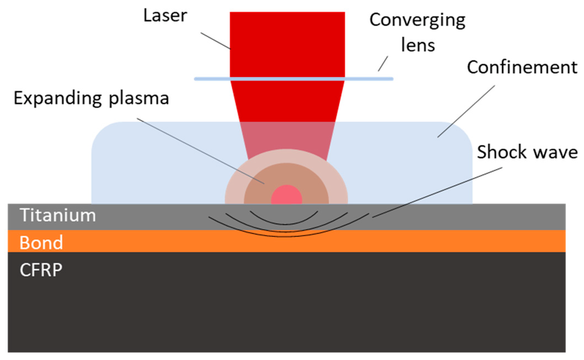
Laser shock is a technique based on laser–matter interaction. The plasma expansion that is obtained when a high-powered laser, with a duration in nanosecond range, is focused onto the surface of a target induces a pulsed pressure, which is the result of the recoil momentum of the ablated material [23]. If the plasma expansion occurs under a confinement regime, the pressure level and duration are increased significantly [24]. The confinement regime needs to be a dielectric material transparent to the laser, such as water, glass, or pliable polymer [14]. The pressure generated by the plasma expansion results in an elastic precursor shock followed by an elastic-plastic compression shock that propagates inside the material. After the plasma expansion, the surface is unloaded and a plastic-decompression shock alongside an elastic-plastic decompression shock begin to propagate and are described as a release wave. The interaction between the release wave and the elastic precursor shock wave develops high localized tensile stresses [25]. Figure 2 is an illustration of the laser-shock principle.

2.1.2. Laser-Shock Configurations

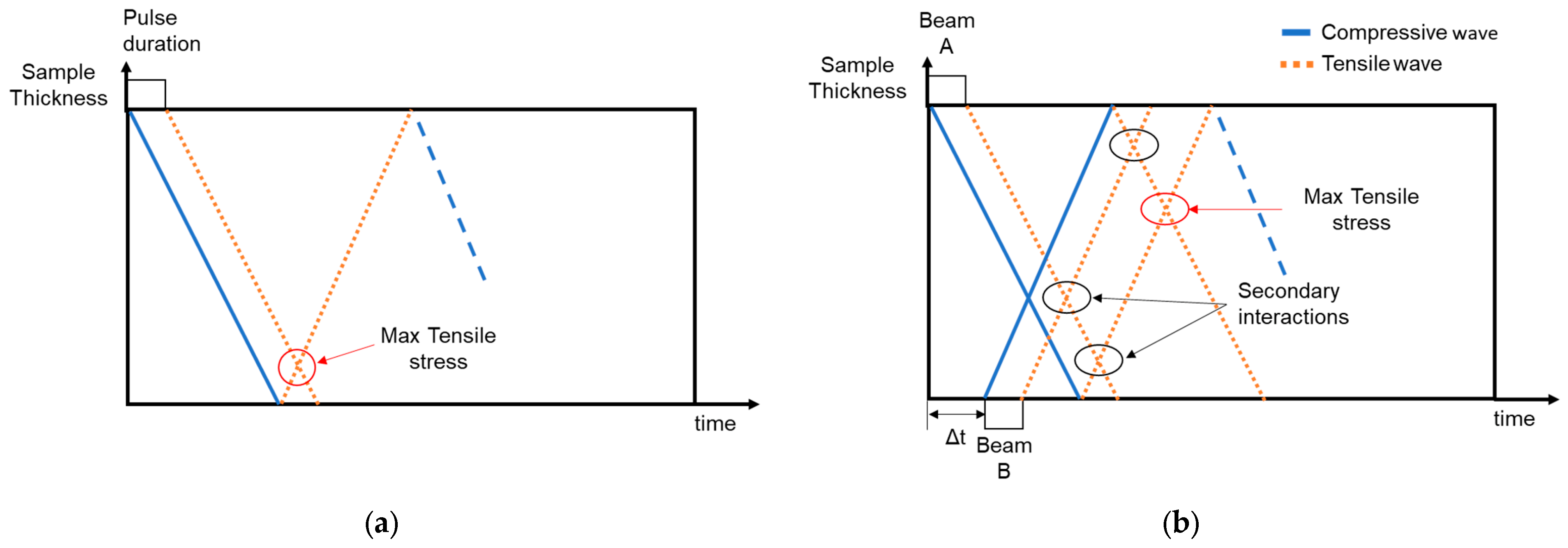
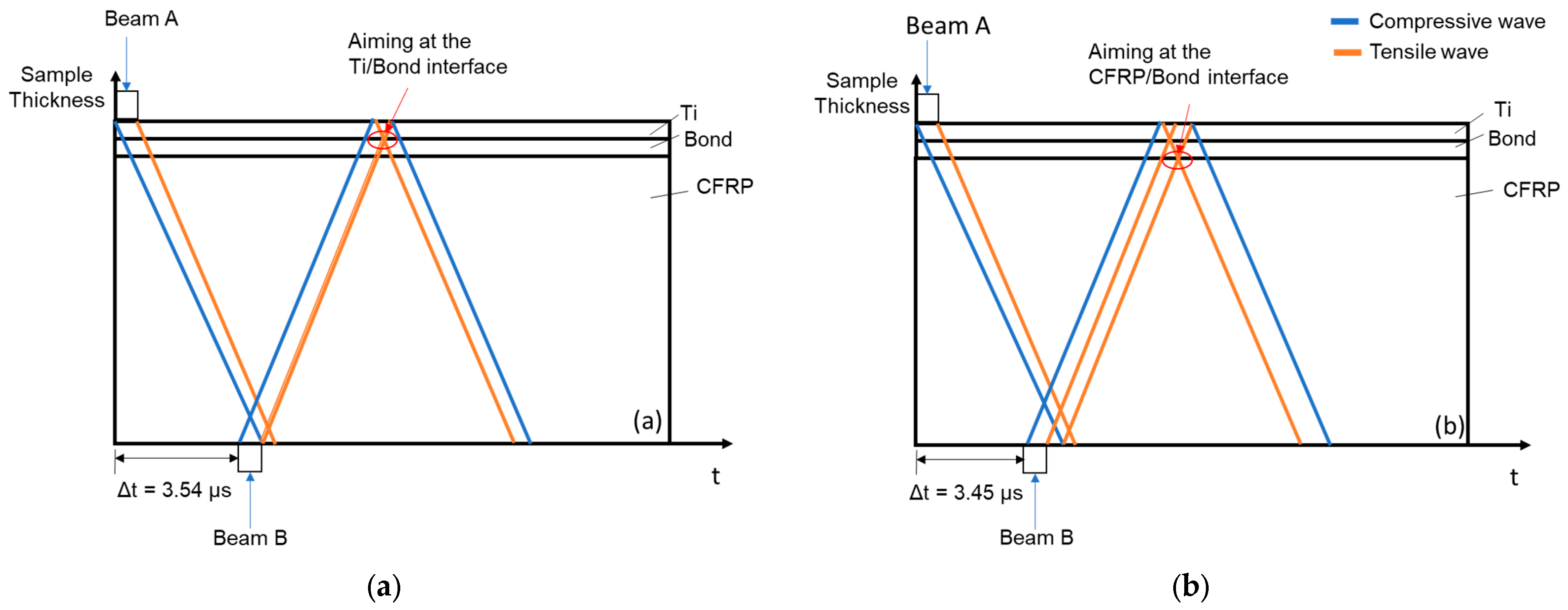
Depending on the configuration of the two beams, different set-ups are possible. To illustrate the wave interactions in the different configurations, it is common in the literature to use simplified space–time diagrams that present stresses, assuming a linear one-dimension propagation though the specimen thickness. Figure 3a demonstrates the standard single-sided shot configuration, where one beam is focused on the surface of the specimen; the high tensile stress area appears near the opposite side of the specimen caused by the interaction between the reflected release wave and the release wave resulting from surface unloading. This interaction is only dependent on specimen geometry and the pulse duration.
Additionally, when both sides of the specimen are irradiated, two shock fronts are created and allowed to propagate in opposite directions [16]. To achieve the symmetric configuration illustrated in Figure 3b, two polarized beams are separated using a 90° polarizer and transported to each side of the specimen using optics. Utilizing the symmetric technique, the maximum tensile stress does not exclusively rely on pulse duration; instead, shifting the location is possible by applying time delay (Δt) between the pulses. Tensile stress areas are still created by the interactions of each individual shock propagating inside the material and their location cannot be controlled; however, the maximum tensile stress is produced by the interference of the two reflected release waves and its position at the material’s thickness depends on the Δt.

2.2. Materials and Specimens

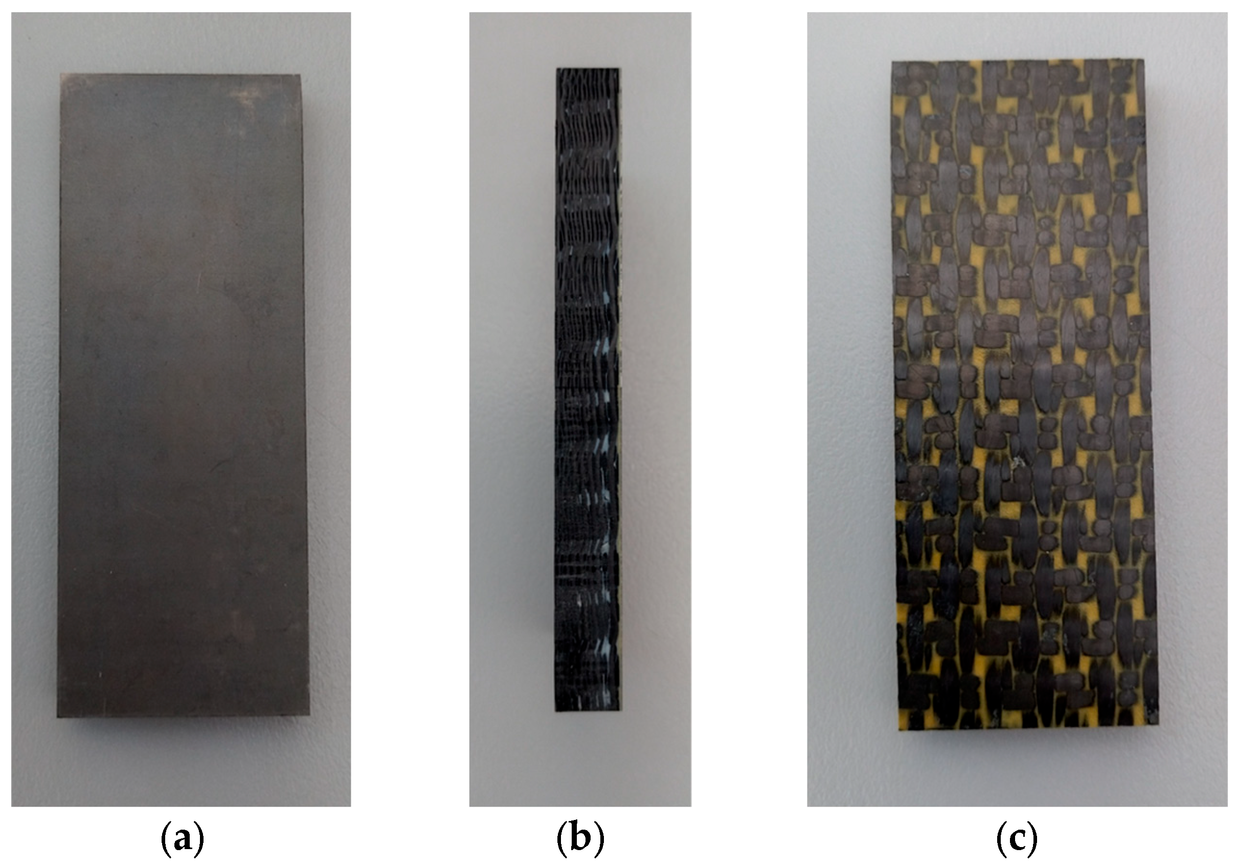
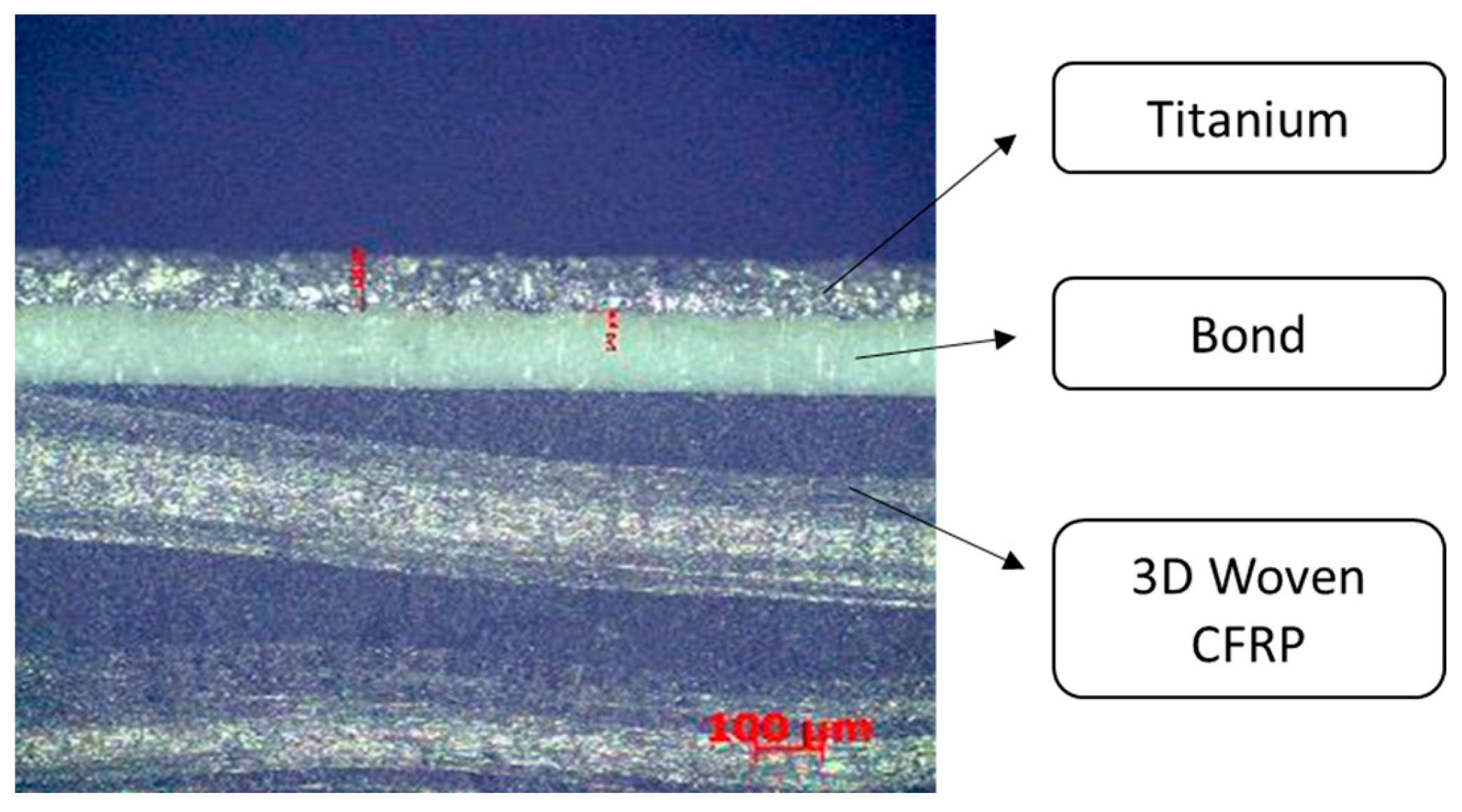
The specimens were provided by Safran in the frame of the MORPHO European project. The composition of the specimens is a 3D-woven CFRP core bonded to a thin Ti alloy edge using an adhesive film. Each specimen was cut by Safran from a single block and the final dimensions of the specimens are 100 mm × 40 mm with a thickness of 10.6 mm. The specimens tested are illustrated in Figure 4 and Figure 5. During all experiments, the composite side of the specimens was covered by a thin aluminum tape. The reasons are twofold: during direct shots on the composite the aluminum acts as an ablation layer, providing higher pressure while protecting the composite from the ablation effects; additionally, aluminum provides a reflective surface that can be used for optical measurements during Ti side-shots.

2.3. Laser Specifications

The experiments were conducted using the Hephaïstos facility located at the Laboratory for Processes and Engineering in Materials and Mechanics (PIMM), ENSAM, ParisTech. The facility uses two Nd:YAG (neodymium-doped yttrium aluminum garnet) Gaia HP lasers from THALES, which can emit synchronized or delayed pulses, at 532 nm with a repetition rate of 2 Hz. The pulse has a gaussian temporal profile with a duration of 7 ns and a maximum energy of 7 J each that can be combined into a 14 J pulse when both lasers are superposed. The beams are focused using an optical lens to control the focal diameter, with a range of 3 to 5 mm. After the focus, a diffractive optical element is used to obtain a uniform top-hat-shaped spatial profile.

2.4. Experimental

2.4.1. Single-Sided Shot Configuration

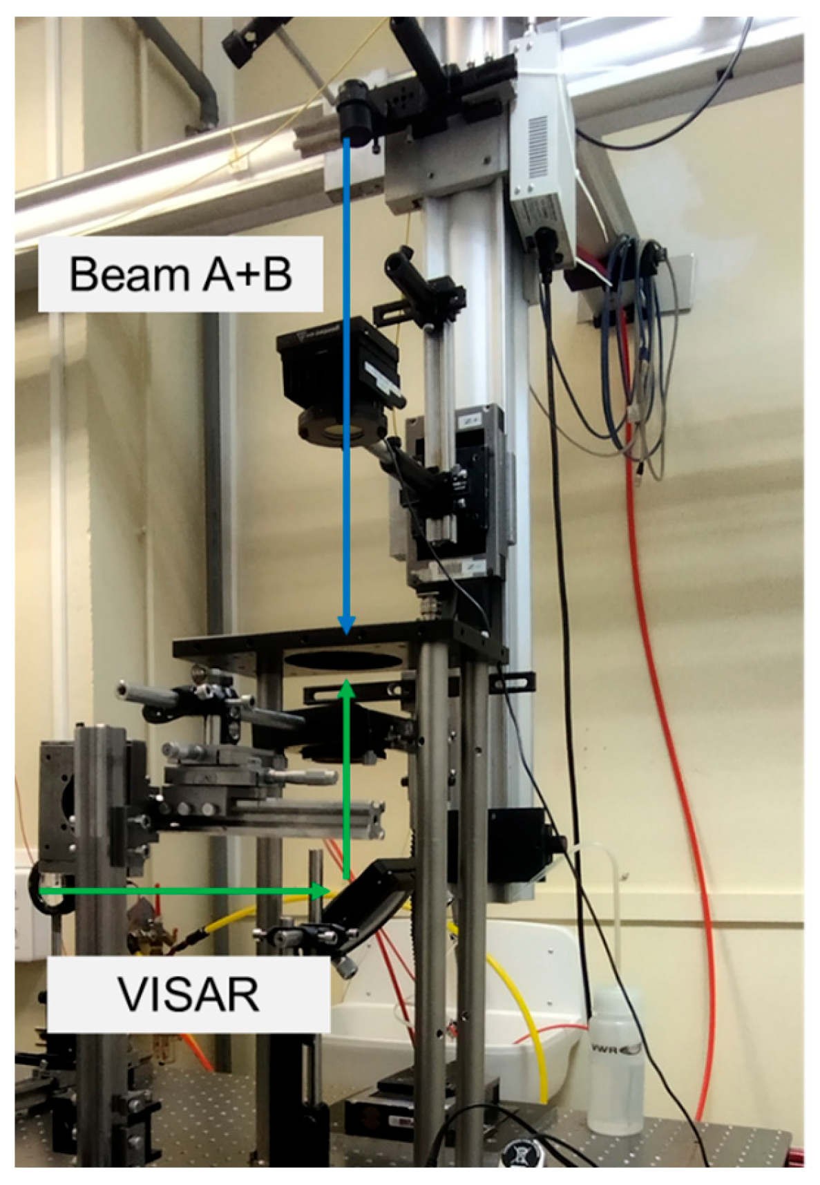
For the first part of the experiments, the single-sided shot configuration was used, as shown in Figure 6. During the experiments, the particle velocity of the free face of the material (opposite to the loading surface) is measured by an optical diagnostic tool called VISAR (Velocity Interferometer System for Any Reflector). VISAR is an interferometer that can measure the doppler shift of a 532 nm wavelength, low-power laser, when it is reflected by a free surface that is moving because of the arrival of a shock wave. The time resolution that the tool provides is 1 ns. The tool has been used in the study of shock waves in solids [18,19,20,23,26] as a method of damage identification during LASAT, or a way to validate numerical models for study and optimization.
This experimental series consists of single-sided shots on both the Ti and CFRP sides of the specimen with laser intensity varying from 1 GW/cm2 to 6 GW/cm2 using water as the confinement regime and a spot diameter of 4 mm. Due to the nature of the 3D-woven composite, it is expected that the VISAR measurements have an increased location dependent variability. This is attributed to the inhomogeneity of the material that results in local stiffness and thickness variations, influencing the particle velocity. To account for the variability of the measurements, each laser intensity experiment was repeated 10 times. Table 1 contains all the single-side shot experiments.

2.4.2. Symmetric Laser Configuration

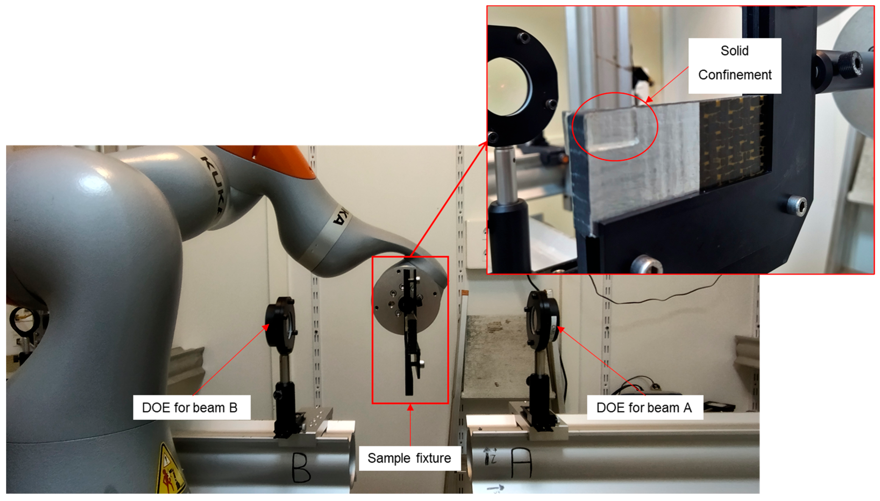
The symmetric configuration uses the same two Nd:YAG lasers, splitting the beams using a polarizer to deliver one beam at each side of the specimen. The symmetric experimental set-up is shown in Figure 7. For this configuration to work, it is important that the two beams are perfectly aligned. To maintain the alignment, movement of the spot is achieved by placing the specimen on a robotic arm (Figure 6). The water confinement regime is challenging in this set-up, and thus, it was replaced by a solid pliable polymer. The shots were focused on the edge of the specimen so that the damage that is created can be visible through an electronic microscope. The energy of each beam was set to 100%, meaning 3.49 J and 5.14 J for beam A and B, respectively. Using a 3.2 mm spot diameter, the resulting laser intensity is 5.45 GW/cm2 for beam A and 7.99 GW/cm2 for beam B.
During the experiments, the delay time can be set between beam A and B with an accuracy of 1 ns. The delay times that were calculated for the specimen are 3.45 μs and 3.55 μs when the tensile zone created by the shock-wave propagation aims to damage the interface between the bond line and the titanium or the bond line and the CFRP, respectively. Shots using a delay between the two mentioned values did not produce any damage; thus, the effort was focused on the creation of debonding caused by adhesive failure, aiming at the interface instead of cohesive failure. Figure 8 illustrates the wave propagation for each time delay.
Previous work [27,28] has shown that damage can be progressively created in a two-step loading. If the first shot provides enough energy to weaken the bond, then a second shot can initiate the debonding. Utilizing this strategy, each spot was shot two times, the first to weaken the bond and the second one to damage it.

3. Results

3.1. Single-Sided Configuration Results

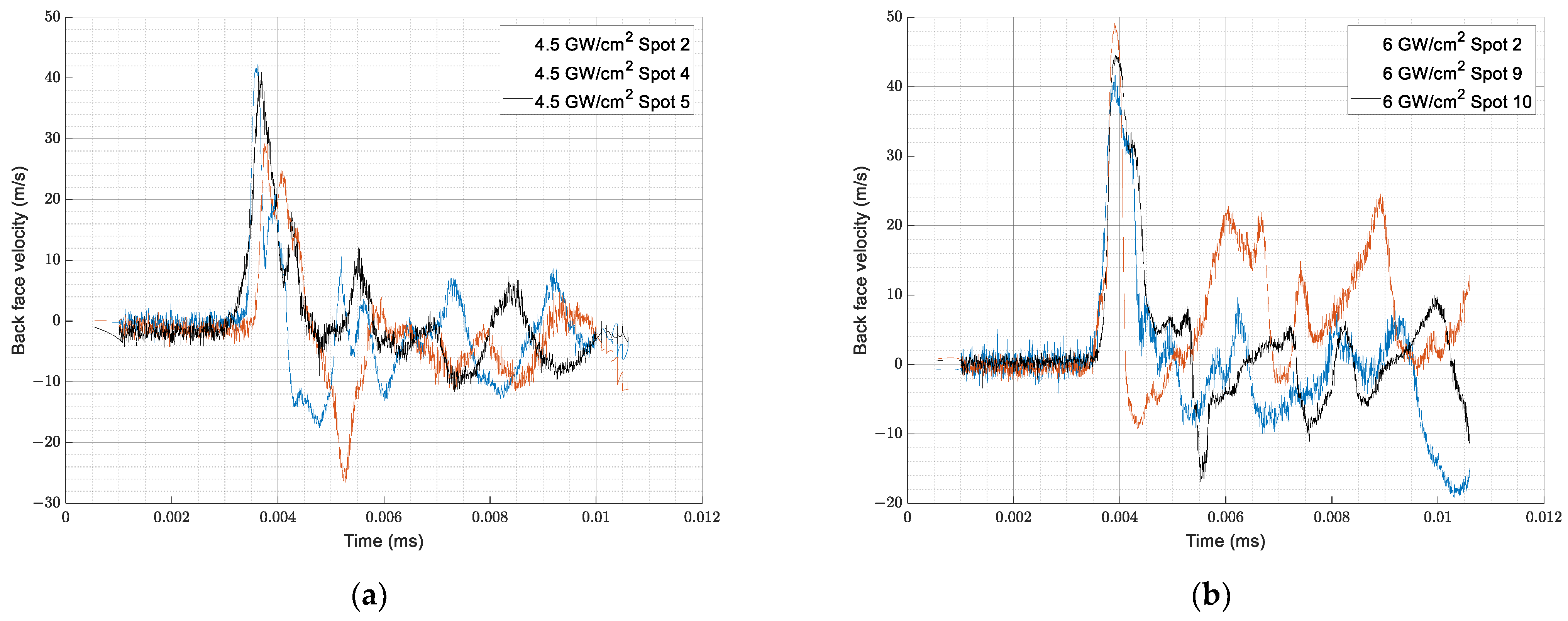
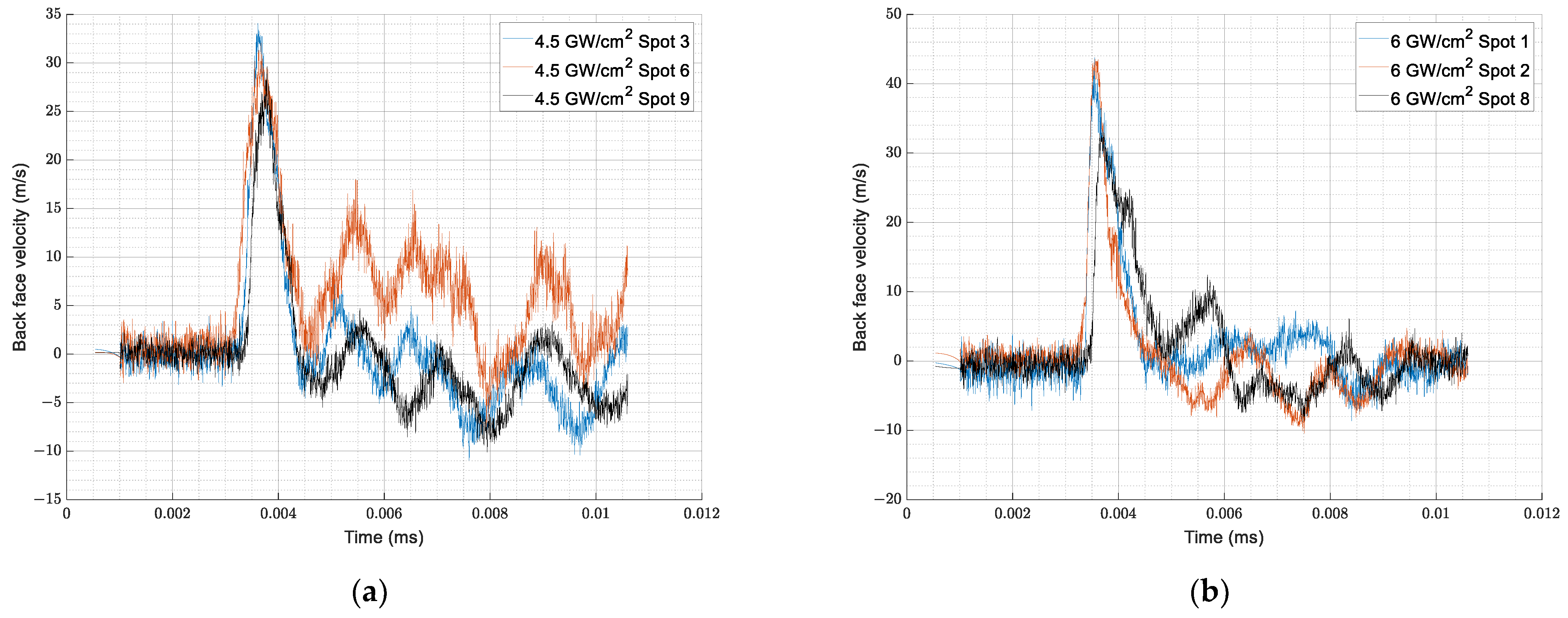
The shots conducted using the single-sided configuration were expected to show a shift in the back-face velocity measurements as the intensity increased, indicating damage at higher energies. Figure 9 and Figure 10 show the back-face velocities of the specimens shot with 4.5 GW/cm2 and 6 GW/cm2 for the Ti side and composite side shots, respectively. Each curve corresponds to a different spot using the same intensity to observe the variability of the measurements. The response of the specimens was identical for lower and higher laser intensities, differentiating only on the peak value of the velocity; this is an indication that no damage was created. It is interesting to mention that Ti side shots have increased variability for the same experimental parameters. Measurements for the Ti side shots are conducted at the surface of the composite, so the inhomogeneous nature of the 3D-woven structure is more dominant for those measurements. On the other hand, the shots conducted at the surface of the CFRP show less variability because the measurements were taken at the surface of the titanium, which is homogenous.
To validate the absence of damage to the specimens, ultrasound tests were used in the form of a C-scan. Observing the C-scan of the 6 GW/cm2, it is clear that no damage was created during the shots. Figure 11 shows the result for the Ti and composite side shots.

3.2. Symmetric Configuration Results

3.2.1. Symmetric Shots Targeted at the Adhesive/CFRP Interface

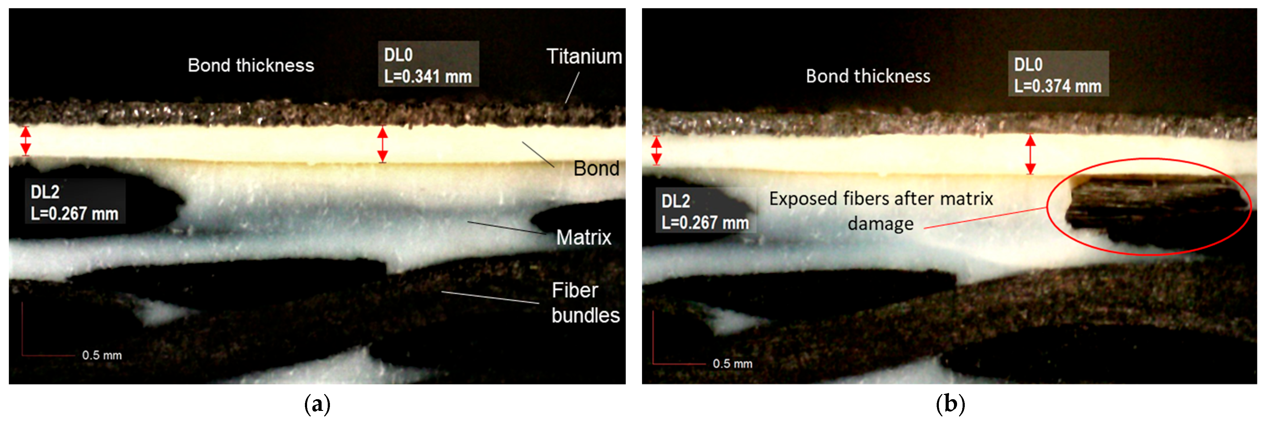
The shots conducted with a delay between pulse A and B of 3.45 μs were aimed at the adhesive/CFRP interface. Figure 12 and Figure 13 are images of an electronic microscope, where the Ti adhesive and CFRP layers are visible. Measurements of the adhesive’s thickness outside and inside the spot area indicate an increase in thickness inside the spot area that is due to plastic deformation of the adhesive. The second shot at the same spot resulted in matrix damage in the composite material. This is visible in Figure 12b where the fibers have been exposed underneath the adhesive layer. The experiment was repeated with the same results in Figure 13.

3.2.2. Symmetric Shots Targeted at the Adhesive/Ti Interface

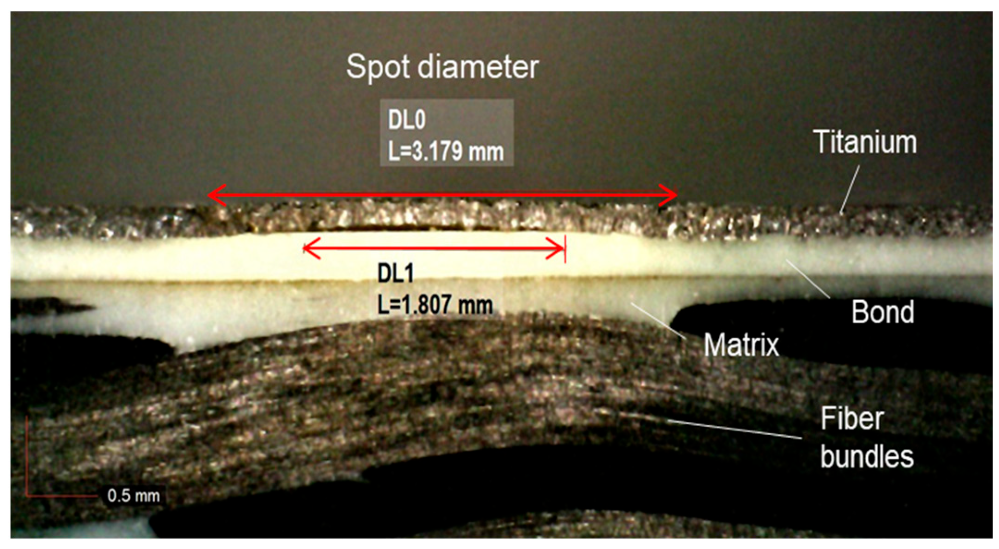
The shots that were conducted using the 3.54 μs delay time between beam A and B have led to adhesive failure at the adhesive/Ti interface, using the same two-shot methodology. After the first shot, the adhesive developed plastic deformation, like the experiments using delay time of 3.45 μs, and the second shot created the debonding, as shown in Figure 14. No other damage was visible other than the debonding.
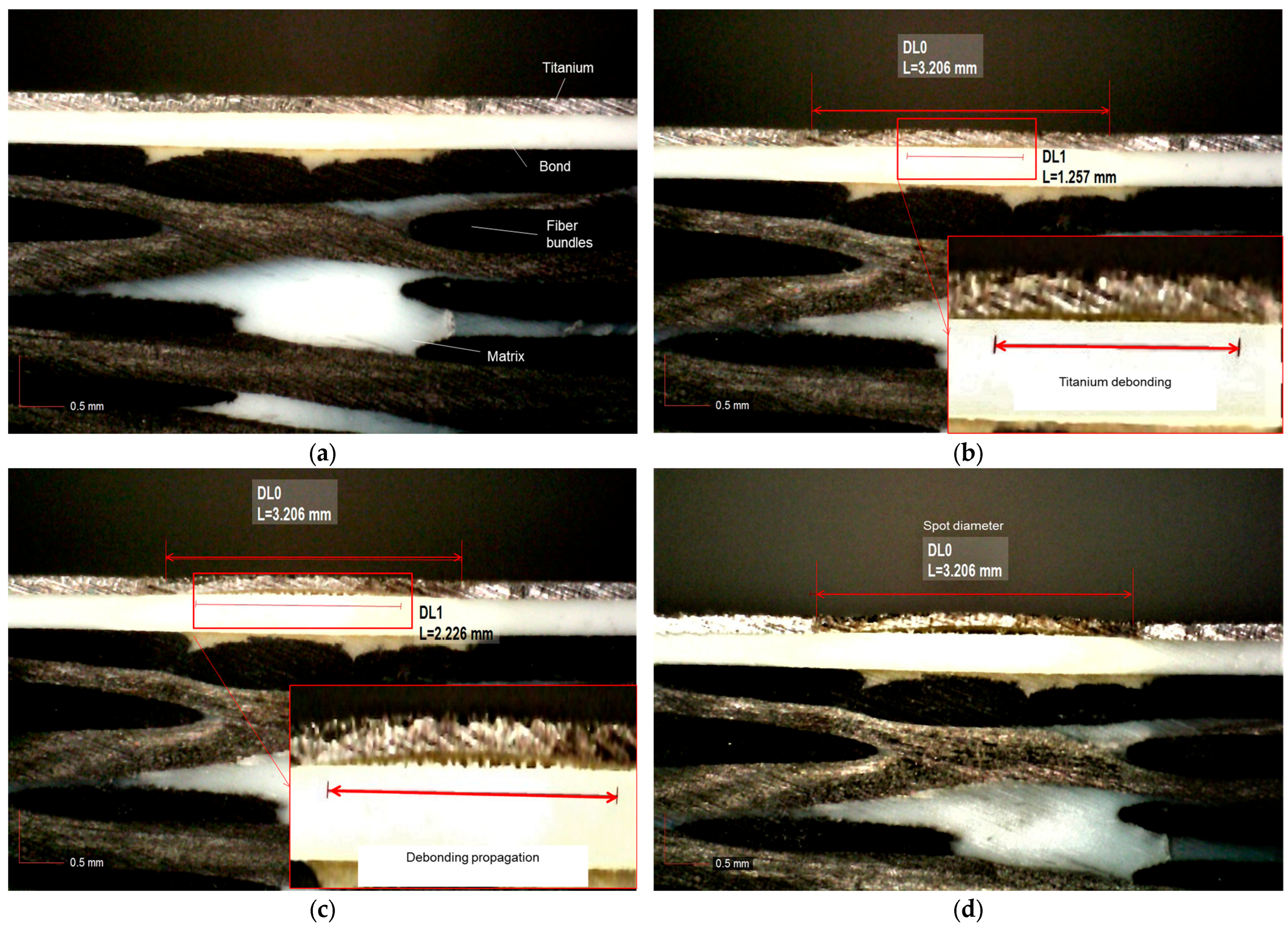
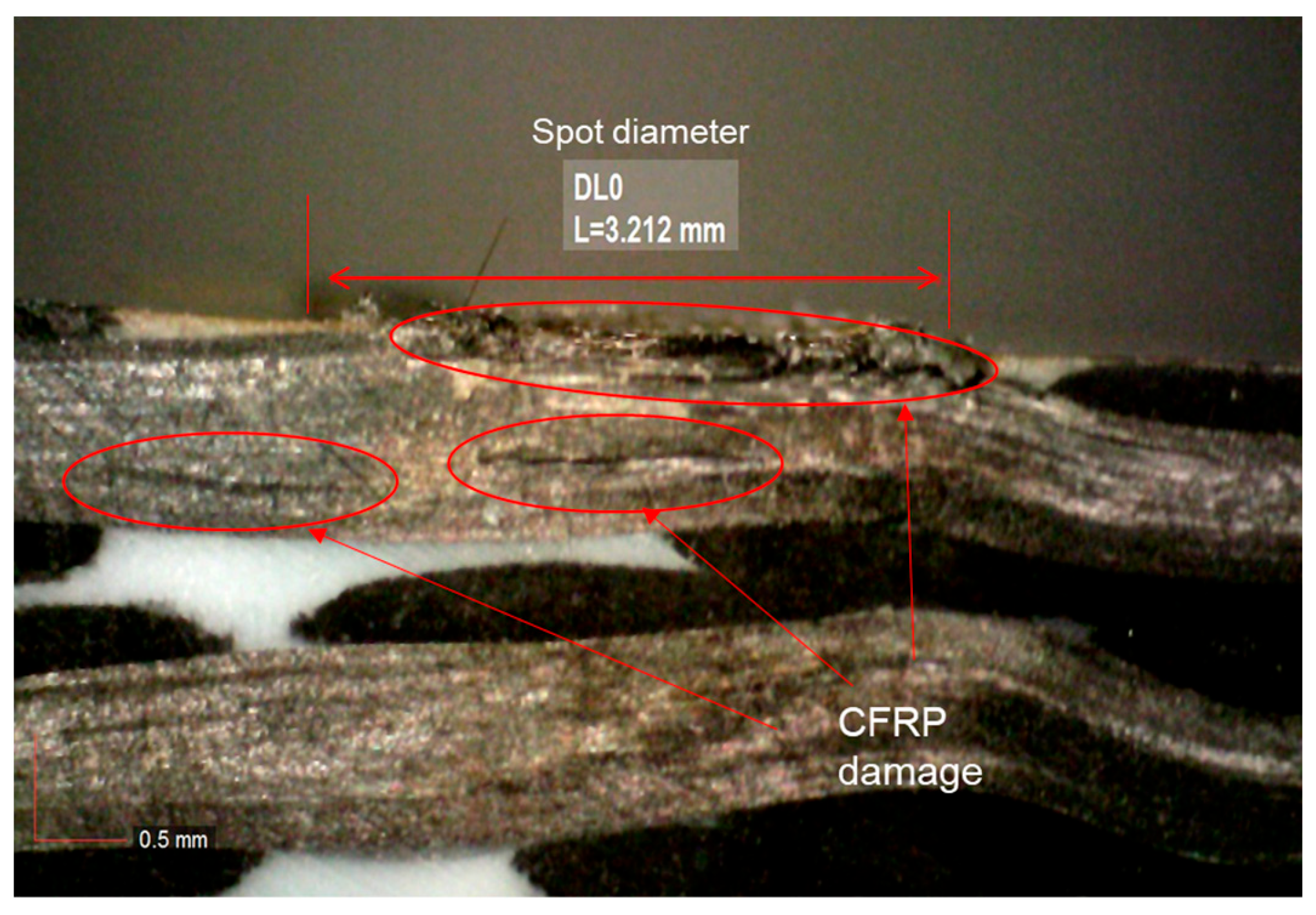
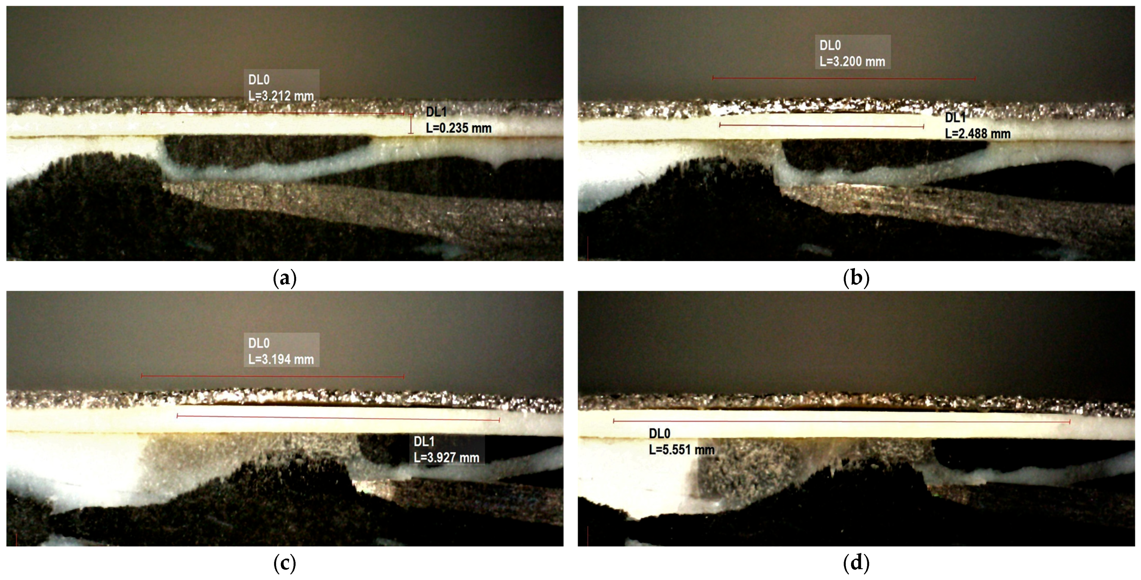
After establishing the capability of the method to create the debonding, two propagation techniques were tested. The first experimental trial employed repeated shots at the same spot. Each consecutive shot increased the debonded area until it became equal to the spot diameter at the fourth shot. Figure 15 shows the propagation of the debonding after each shot. This method, although effective, produced fiber damage to the CFRP close to the free surface of the composite. Figure 16 is a microscope picture of the damaged CFRP.
The second approach for the propagation of the debonding is the moving spot. The sequence of shots during this trial is the following: the first two shots initiate the debonding; then, the spot is moved by 2 mm and two more shots are used to propagate the debonding. Finally, the spot is moved by another 2 mm in the same direction, and after two more shots, the final debonding was measured as 5.5 mm. The progression of damage is shown in Figure 17. Visual inspection of the specimen using the electronic microscope did not show any indication of damage to the CFRP.

4. Discussion

The symmetric laser-shock configuration shows that it is possible to create a debonding between the Ti and CFRP by carefully calibrating the delay time of the two shots. This work proved experimentally the hypothesis that was investigated numerically in previous work [27,28] that the laser-shock technique can progressively create damage by shooting multiple times at the same spot. Additionally, the propagation of the debonding can be also achieved using repetitive shots at the same spot but also by moving the spot. The experiments indicated that repetitive shots at the same spot have an upper limit in their effectiveness because they can damage the involved adherents, as is the case of the first trial, which damaged the CFRP at the area where secondary tensile interactions are predicted to occur. Furthermore, this was the first time that a specimen of this thickness was tested, and although challenging, it is possible to disassemble even thick structures like an aircraft engine fan blade.
Although the first steps of the process development show promise, the implementation of the technique to a full-scale industrial disassembly application needs improvement. First, the symmetric process is tedious and should be streamlined for automation used in industrial-scale disassembly. This can be achieved using a continuous water stream as the confinement regime instead of the single-use solid polymer. In addition, the symmetric configuration, although effective, is restrictive in its use as both faces of the material should be accessible and taken into account during the implementation of the process. Furthermore, the shot sequence can be optimized for maximizing the debonded area. That, as well as the calculation of the optimal time delay, can be achieved by a simulation of the process using the data created by this experimental series to validate a digital twin of the specimen.

5. Conclusions

A novel disassembly process of adhesively bonded structures is being developed using the laser-shock technique. Two experimental trials were conducted to prove the method’s ability to debond a thin titanium leading edge from a 3D-woven composite core. The single-shot configuration experiments revealed that it is not possible to create a debonding on the specimen. The method’s inability is attributed to the fact that the required stress field near the bond line cannot be created by one shot. Nevertheless, the experimental series provided useful back-face velocity measurements that can be used to validate numerical models for further optimization of the method. The second experimental series that was conducted using the symmetric configuration succeeded to create and propagate a debonding between the composite and the titanium leading edge. Two methods of propagation were tested; on the one hand, subsequent shots at the same spot, although successful for propagation of the debonding, caused severe damage to the CFRP, something the process is aiming to avoid. On the other hand, moving the spot proved to be the most sufficient methodology for the debonding propagation. Additionally, using the symmetric configuration, it is possible to control with accuracy the concentration of tensile stresses by shifting the delay between the beams. This is showcased by the damage creation differences once the wave interference was aimed at the interface between the Ti/adhesive and CFRP/adhesive, respectively. Finally, although the results are promising in creating and propagating a debonding, to use the technique as a disassembly process both the damage initiation and the propagation need optimization.

Author Contributions

Conceptualization, L.B. and K.T.; methodology, P.K., S.U., K.T. and L.B.; investigation, P.K. and S.U.; resources, K.T. and L.B.; writing—original draft preparation, P.K. and K.T.; writing—review and editing, K.T., S.U. and L.B.; visualization, P.K. All authors have read and agreed to the published version of the manuscript.

Funding

The research leading to these results is part of the MORPHO project and has received funding from the European Union’s Horizon 2020 research and innovation program under grant agreement No. 101006854.

Data Availability Statement

Not applicable.

Conflicts of Interest

The authors declare no conflict of interest.

References

  1. Liu, W.; Huang, H.; Zhu, L.; Liu, Z. Integrating Carbon Fiber Reclamation and Additive Manufacturing for Recycling CFRP Waste. Compos. Part B Eng. 2021, 215, 108808. [Google Scholar] [CrossRef]
  2. Meyer, L.O.; Schulte, K.; Grove-Nielsen, E. CFRP-Recycling Following a Pyrolysis Route: Process Optimization and Potentials. J. Compos. Mater. 2009, 43, 1121–1132. [Google Scholar] [CrossRef]
  3. Dauguet, M.; Mantaux, O.; Perry, N.; Zhao, Y.F. Recycling of CFRP for High Value Applications: Effect of Sizing Removal and Environmental Analysis of the SuperCritical Fluid Solvolysis. Procedia CIRP 2015, 29, 734–739. [Google Scholar] [CrossRef]
  4. Moslehi, A.; Ajji, A.; Heuzey, M.; Rahimizadeh, A.; Lessard, L. Polylactic Acid/Recycled Wind Turbine Glass Fiber Composites with Enhanced Mechanical Properties and Toughness. J. Appl. Polym. Sci 2022, 139, 51934. [Google Scholar] [CrossRef]
  5. Sabaghi, M.; Cai, Y.; Mascle, C.; Baptiste, P. Sustainability Assessment of Dismantling Strategies for End-of-Life Aircraft Recycling. Resour. Conserv. Recycl. 2015, 102, 163–169. [Google Scholar] [CrossRef]
  6. Zhao, X.; Verhagen, W.J.C.; Curran, R. Disposal and Recycle Economic Assessment for Aircraft and Engine End of Life Solution Evaluation. Appl. Sci. 2020, 10, 522. [Google Scholar] [CrossRef]
  7. Tserpes, K. Adhesive Bonding of Aircraft Structures. In Revolutionizing Aircraft Materials and Processes; Pantelakis, S., Tserpes, K., Eds.; Springer: Cham, Switzerland, 2020; pp. 337–357. ISBN 978-3-030-35346-9. [Google Scholar]
  8. Sato, C.; Carbas, R.J.C.; Marques, E.A.S.; Akhavan-Safar, A.; da Silva, L.F.M. Effect of Disassembly on Environmental and Recycling Issues in Bonded Joints. In Adhesive Bonding; Elsevier: Amsterdam, The Netherlands, 2021; pp. 407–436. ISBN 978-0-12-819954-1. [Google Scholar]
  9. Hutchinson, A.; Liu, Y.; Lu, Y. Overview of Disbonding Technologies for Adhesive Bonded Joints. J. Adhes. 2017, 93, 737–755. [Google Scholar] [CrossRef]
  10. Banea, M.D. Debonding on Demand of Adhesively Bonded Joints: A Critical Review. Rev. Adhes Adhes. 2019, 7, 33–50. [Google Scholar] [CrossRef]
  11. Banea, M.D.; da Silva, L.F.M.; Carbas, R.J.C. Debonding on Command of Adhesive Joints for the Automotive Industry. Int. J. Adhes. Adhes. 2015, 59, 14–20. [Google Scholar] [CrossRef]
  12. Piazza, G.; Burczyk, M.; Gerini-Romagnoli, M.; Belingardi, G.; Nassar, S.A. Effect of Thermally Expandable Particle Additives on the Mechanical and Reversibility Performance of Adhesive Joints. J. Adv. Join. Process. 2022, 5, 100088. [Google Scholar] [CrossRef]
  13. Ivetic, G. Three-Dimensional FEM Analysis of Laser Shock Peening of Aluminium Alloy 2024-T351 Thin Sheets. Surf. Eng. 2011, 27, 445–453. [Google Scholar] [CrossRef]
  14. Le Bras, C.; Rondepierre, A.; Seddik, R.; Scius-Bertrand, M.; Rouchausse, Y.; Videau, L.; Fayolle, B.; Gervais, M.; Morin, L.; Valadon, S.; et al. Laser Shock Peening: Toward the Use of Pliable Solid Polymers for Confinement. Metals 2019, 9, 793. [Google Scholar] [CrossRef]
  15. Ecault, R.; Touchard, F.; Boustie, M.; Berthe, L.; Dominguez, N. Numerical Modeling of Laser-Induced Shock Experiments for the Development of the Adhesion Test for Bonded Composite Materials. Compos. Struct. 2016, 152, 382–394. [Google Scholar] [CrossRef]
  16. Sagnard, M.; Ecault, R.; Touchard, F.; Boustie, M.; Berthe, L. Development of the Symmetrical Laser Shock Test for Weak Bond Inspection. Opt. Laser Technol. 2019, 111, 644–652. [Google Scholar] [CrossRef]
  17. Arrigoni, M. Inputs of Numerical Simulation into the Development of Shock Adhesion Tests on Advanced Materials. Int. J. Struct. Glass Adv. Mater. Res. 2020, 4, 1–9. [Google Scholar] [CrossRef]
  18. Ecault, R.; Touchard, F.; Berthe, L.; Boustie, M. Laser Shock Adhesion Test Numerical Optimization for Composite Bonding Assessment. Compos. Struct. 2020, 247, 112441. [Google Scholar] [CrossRef]
  19. Tserpes, K.; Papadopoulos, K.; Unaldi, S.; Berthe, L. Development of a Numerical Model to Simulate Laser-Shock Paint Stripping on Aluminum Substrates. Aerospace 2021, 8, 233. [Google Scholar] [CrossRef]
  20. Ünaldi, S.; Papadopoulos, K.; Rondepierre, A.; Rouchausse, Y.; Karanika, A.; Deliane, F.; Tserpes, K.; Floros, G.; Richaud, E.; Berthe, L. Towards Selective Laser Paint Stripping Using Shock Waves Produced by Laser-Plasma Interaction for Aeronautical Applications on AA 2024 Based Substrates. Opt. Laser Technol. 2021, 141, 107095. [Google Scholar] [CrossRef]
  21. Papadopoulos, K.; Tserpes, K. Analytical and Numerical Modeling of Stress Field and Fracture in Aluminum/Epoxy Interface Subjected to Laser Shock Wave: Application to Paint Stripping. Materials 2022, 15, 3423. [Google Scholar] [CrossRef]
  22. Ghrib, M.; Berthe, L.; Mechbal, N.; Rébillat, M.; Guskov, M.; Ecault, R.; Bedreddine, N. Generation of Controlled Delaminations in Composites Using Symmetrical Laser Shock Configuration. Compos. Struct. 2017, 171, 286–297. [Google Scholar] [CrossRef]
  23. Fabbro, R.; Peyre, P.; Berthe, L.; Scherpereel, X. Physics and Applications of Laser-Shock Processing. J. Laser Appl. 1998, 10, 265–279. [Google Scholar] [CrossRef]
  24. Fairand, B.P.; Clauer, A.H. Laser Generation of High-amplitude Stress Waves in Materials. J. Appl. Phys. 1979, 50, 1497–1502. [Google Scholar] [CrossRef]
  25. Davison, L.W. Fundamentals of Shock Wave Propagation in Solids; Shock wave and high pressure phenomena; Springer: Berlin/Heidelberg, Germany, 2008; ISBN 978-3-540-74568-6. [Google Scholar]
  26. Scius-Bertrand, M.; Videau, L.; Rondepierre, A.; Lescoute, E.; Rouchausse, Y.; Kaufman, J.; Rostohar, D.; Brajer, J.; Berthe, L. Laser Induced Plasma Characterization in Direct and Water Confined Regimes: New Advances in Experimental Studies and Numerical Modelling. J. Phys. D Appl. Phys. 2021, 54, 055204. [Google Scholar] [CrossRef]
  27. Kormpos, P.; Tserpes, K.; Floros, G. Towards Simulation of Disassembly of Bonded Composite Parts Using the Laser Shock Technique. IOP Conf. Ser. Mater. Sci. Eng. 2022, 1226, 012081. [Google Scholar] [CrossRef]
  28. Kormpos, P.; Unaldi, S.; Ayad, M.; Berthe, L.; Tserpes, K. Towards the Development of a Laser Shock-Based Disassembly Process for Adhesively Bonded Structural Parts: Experiments and Numerical Simulation. In Proceedings of the 20th European Conference on Composite Materials—Composites Meet Sustainability B, Lausanne, Switzerland, 26–30 June 2022; pp. 873–880. [Google Scholar] [CrossRef]
Figure 1. Current EOL strategies sorted based on their cost–benefit ratio.
Processes 11 00506 g001
Figure 2. Schematic representation of laser-generated shockwave.
Processes 11 00506 g002
Figure 3. Space–time diagram for single shot (a) and symmetric (b) configuration.
Processes 11 00506 g003
Figure 4. Specimen used for laser-shock experiments. (a) Top view; (b) side view; (c) bottom view.
Processes 11 00506 g004
Figure 5. Microscope image of the interface between CFRP and Ti.
Processes 11 00506 g005
Figure 6. Single-sided laser experimental set-up.
Processes 11 00506 g006
Figure 7. Symmetric experimental set-up.
Processes 11 00506 g007
Figure 8. Space–time diagrams showcasing the wave propagation for delay times of (a) 3.54 μs and (b) 3.45 μs.
Processes 11 00506 g008
Figure 9. Back-face velocity measurements for Ti side shots for (a) 4.5 GW/cm2 and (b) 6 GW/cm2.
Processes 11 00506 g009
Figure 10. Back-face velocity measurements for CFRP side shots for (a) 4.5 GW/cm2 and (b) 6 GW/cm2.
Processes 11 00506 g010
Figure 11. C-scan for the 6 GW/cm2 specimen: composite side (a) and Ti side (b).
Processes 11 00506 g011
Figure 12. Symmetric shot aiming at the interface between CFRP and adhesive. (a) Plastic deformation caused by the first shot; (b) matrix damage caused by the second shot.
Processes 11 00506 g012
Figure 13. Repeated experiments for matrix damage. (a) Deformation after the first shot; (b) exposed fibers after the second shot.
Processes 11 00506 g013
Figure 14. Debonding between titanium and adhesive after two symmetric shots with delay of 3.54 μs.
Processes 11 00506 g014
Figure 15. Consecutive shots at the same spot: (a) healthy specimen; (b) debonding initiation after two shots; (c) debonding propagation after the third shot; (d) debonding equal to the spot diameter.
Processes 11 00506 g015
Figure 16. Fiber damage at the free surface of the composite after four consecutive shots at the same spot.
Processes 11 00506 g016
Figure 17. Damage propagation using a moving spot: (a) healthy specimen; (b) debonding initiation after two shots; (c) debonding propagation, after moving the spot by 2 mm and shooting two times; (d) final damage after repeating the previous step.
Processes 11 00506 g017
Table 1. Experiments with the single-sided laser configuration.
ExperimentNumber of SpecimensLaser IntensityNumber of Shots
Titanium side shots with VISAR41.2 GW/cm240
(10/specimen)
3 GW/cm2
4.5 GW/cm2
6 GW/cm2
CFRP side shots with VISAR41.2 GW/cm240
(10/specimen)
3 GW/cm2
4.5 GW/cm2
6 GW/cm2
Disclaimer/Publisher’s Note: The statements, opinions and data contained in all publications are solely those of the individual author(s) and contributor(s) and not of MDPI and/or the editor(s). MDPI and/or the editor(s) disclaim responsibility for any injury to people or property resulting from any ideas, methods, instructions or products referred to in the content.