
Design and Experimental Analysis of an Adhesive Joint for a Hybrid Automotive Wheel

 ,
,
Abstract
:
1. Introduction
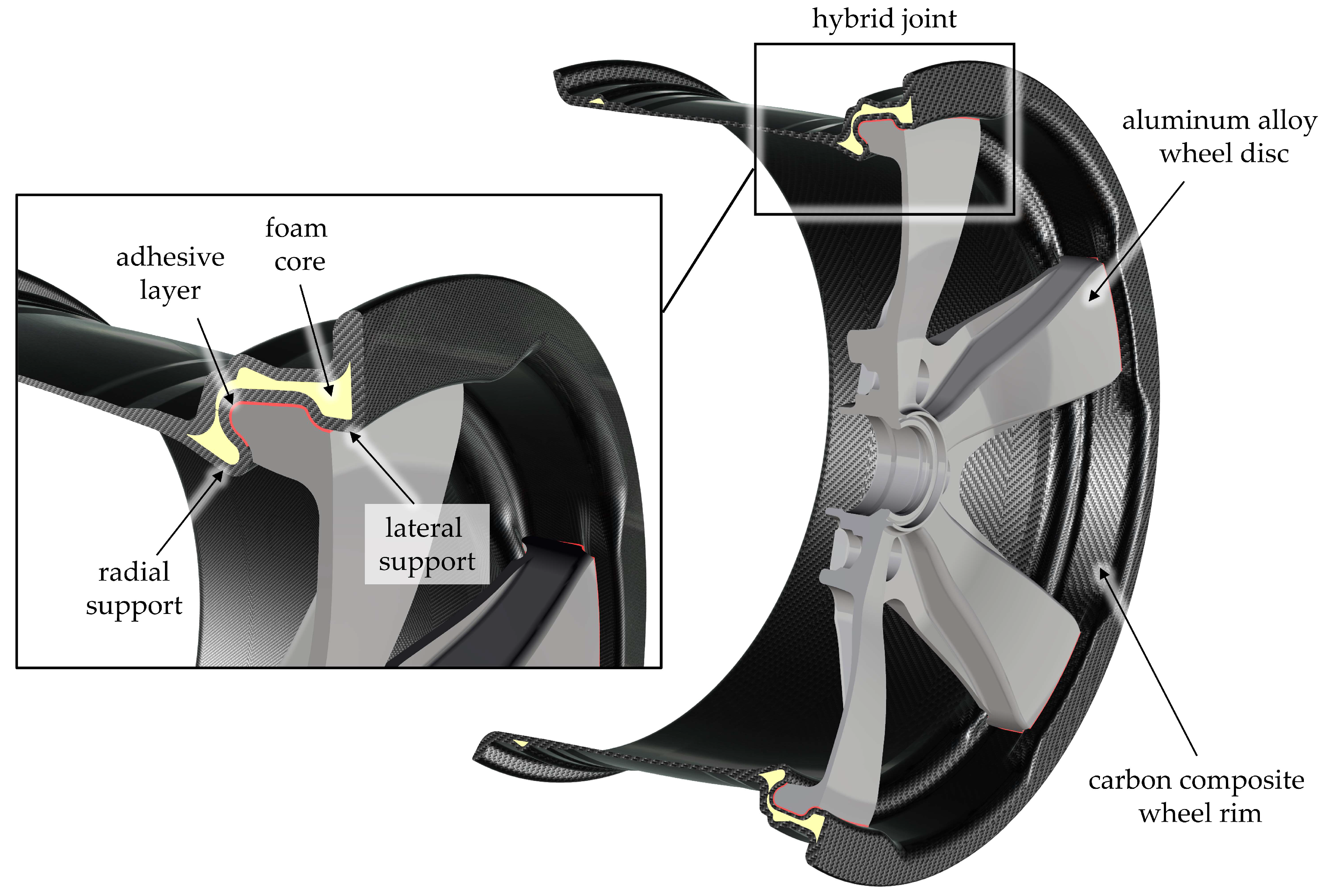
2. Design of an Adhesive Joint for the Hybrid Wheel
2.1. Wheel Requirements
2.2. Material Selection
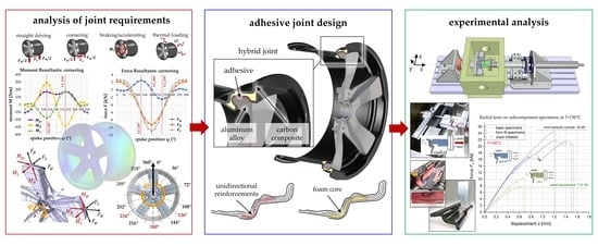
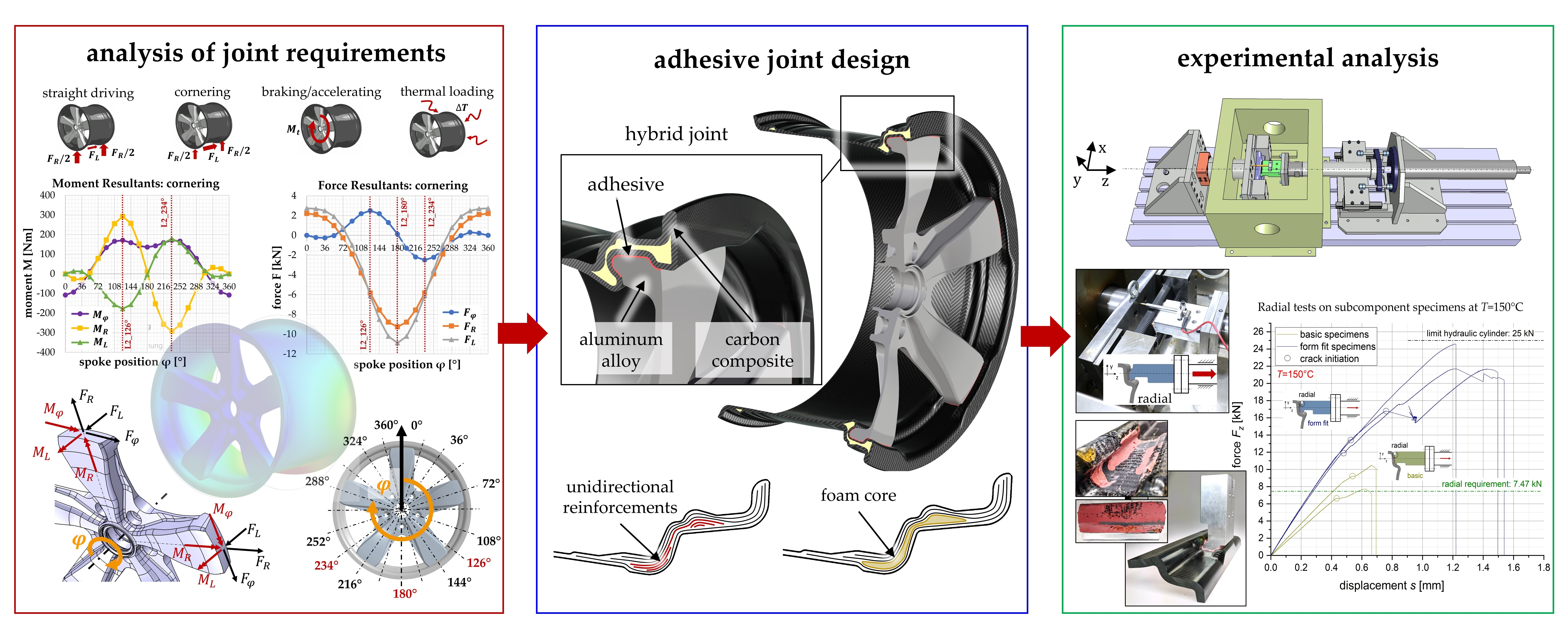
2.3. Analysis of Joint Requirements
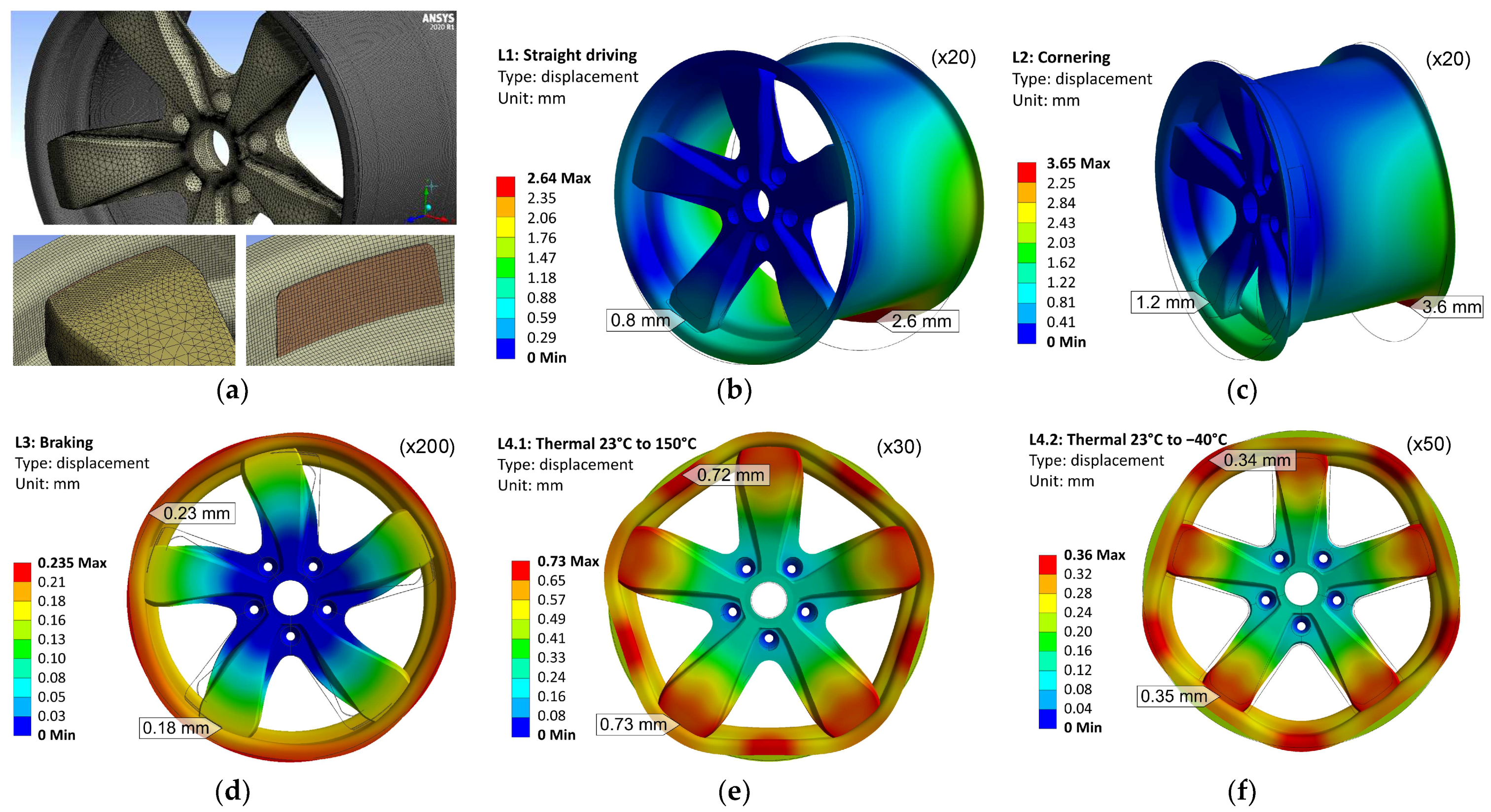
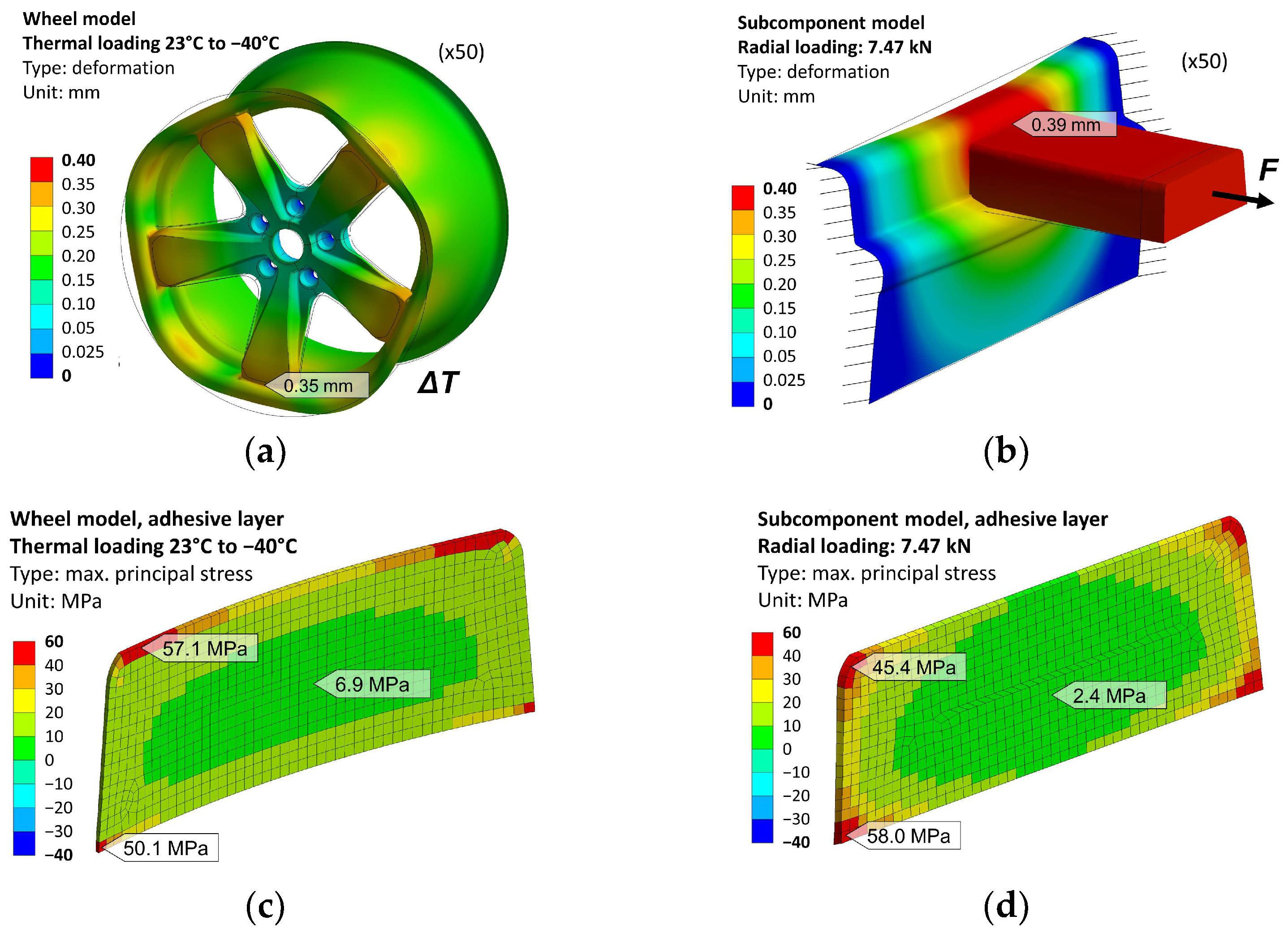
2.3.1. Finite Element Model
2.3.2. Wheel Deformation in Different Load Cases
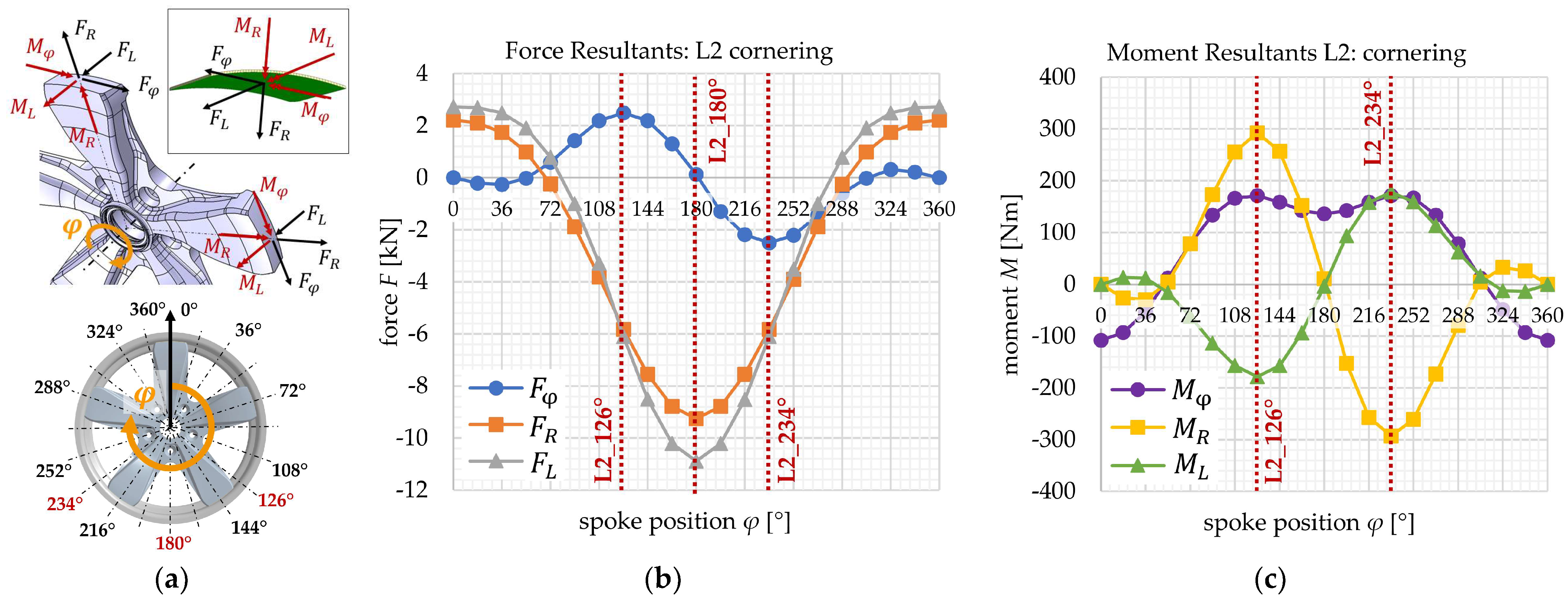
2.3.3. Force and Moment Resultants within the Joint
- The high radial force resultant of +14.08 kN in L4.2 leads to critical tensional loading of the joint, due to the significantly lower tensional strength compared to the compressional strength of the adhesive.
- The high lateral force resultant of −10.89 kN in L2 leads to critical shear loading.
- The circumferential and lateral moment resultants and can be considered more critical than the radial moment resultant , because they lead to out-of-plane pealing stresses rather than in-plane shear stresses within the adhesive layer.
- The braking/accelerating load case can be considered as the least critical load case, resulting in rather low stress states.
2.4. Joint Design
- the adaption of the fiber layup in the composite rim flange;
- the geometrical joint design with a form-fitted radial and lateral support.
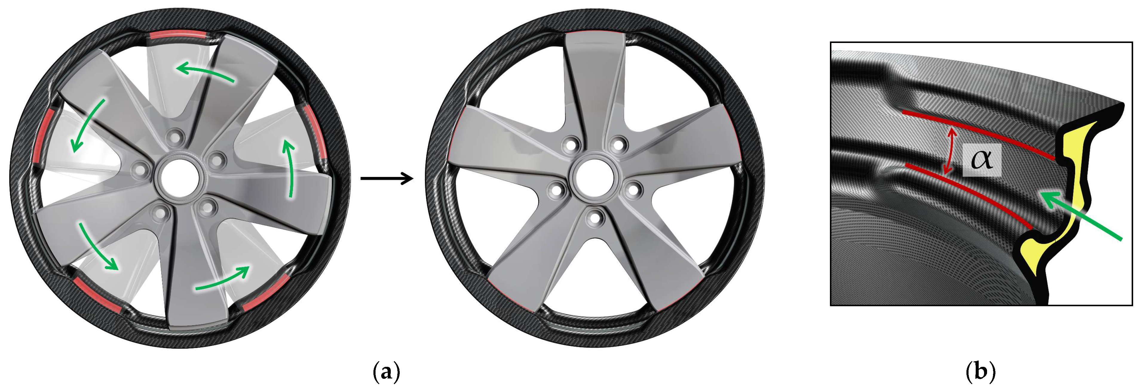
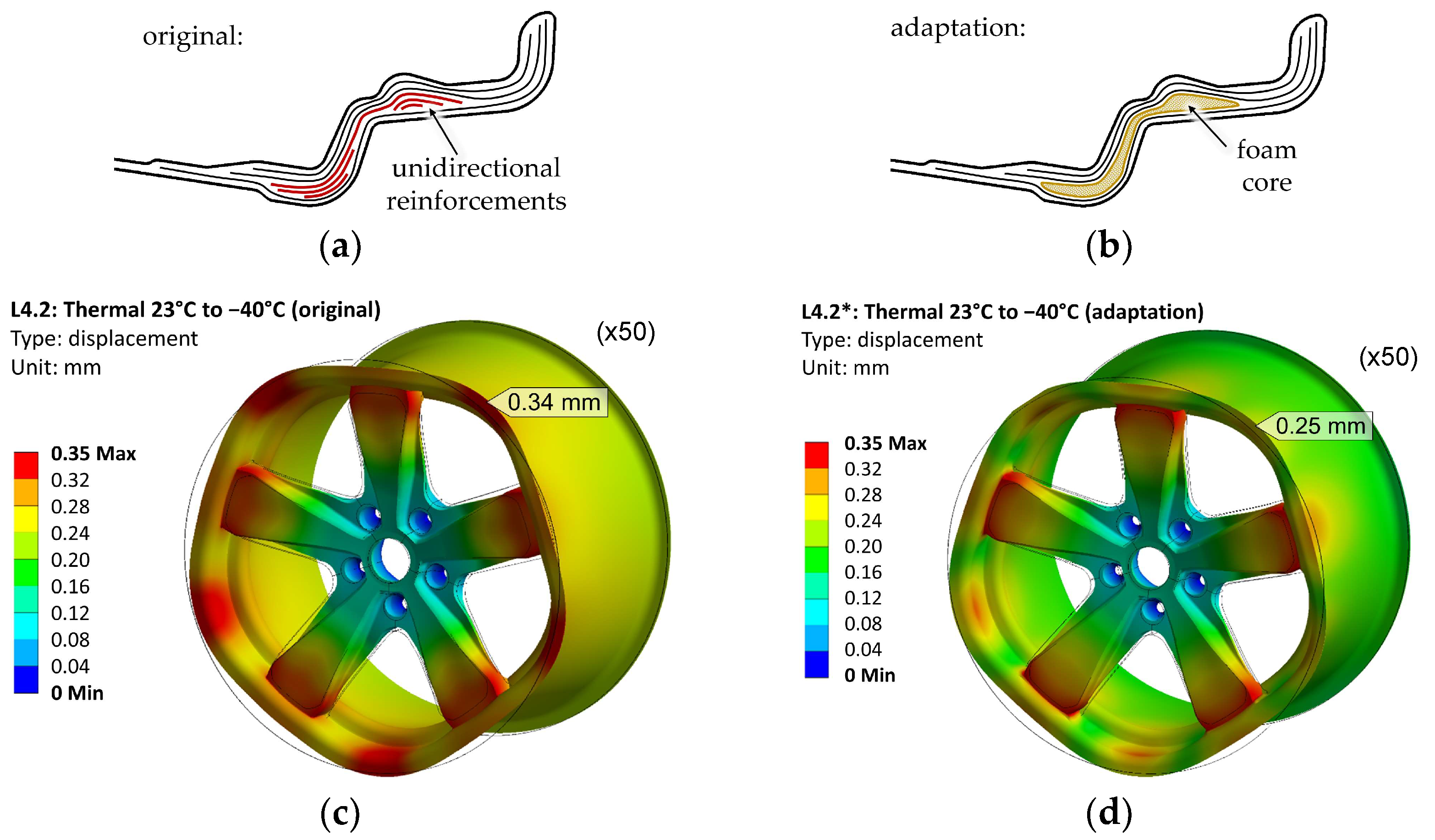
2.4.1. Adaption of the Fiber Layup for the Composite Rim
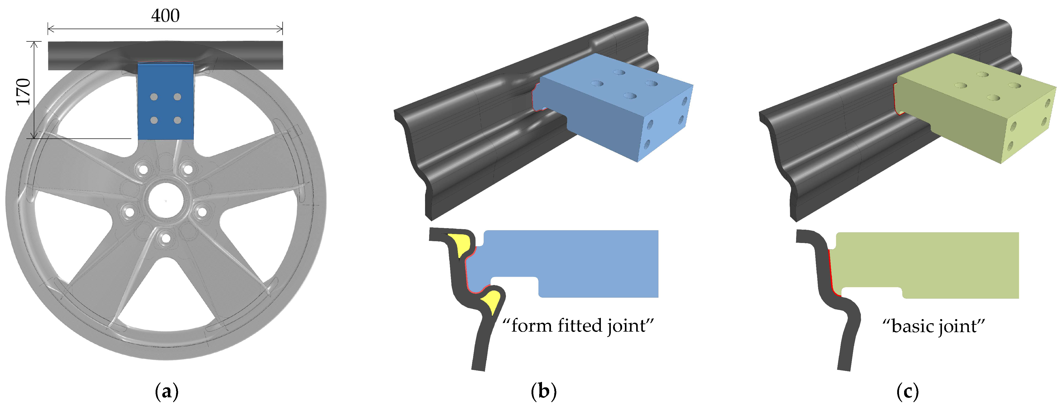
2.4.2. Geometrical Joint Design
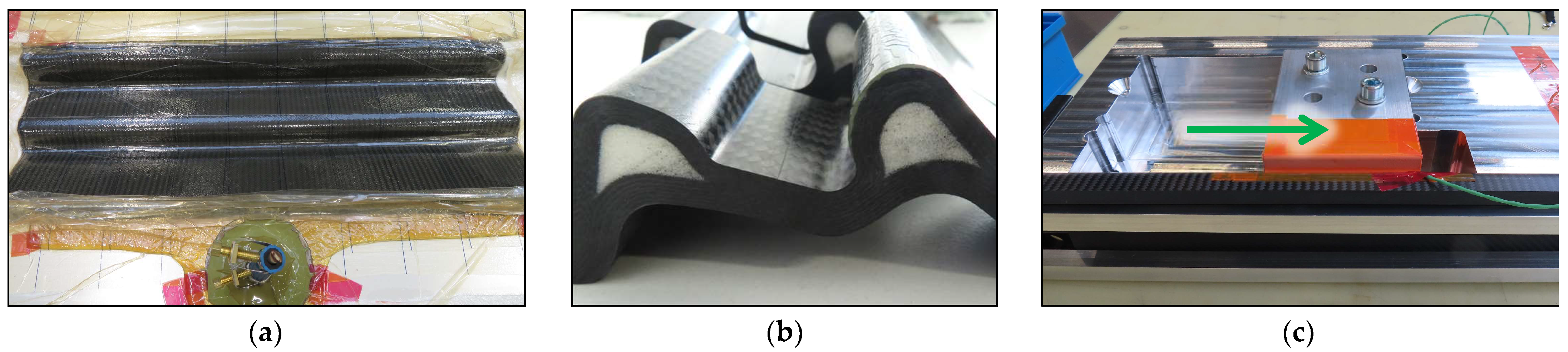
2.4.3. Manufacturing Concept
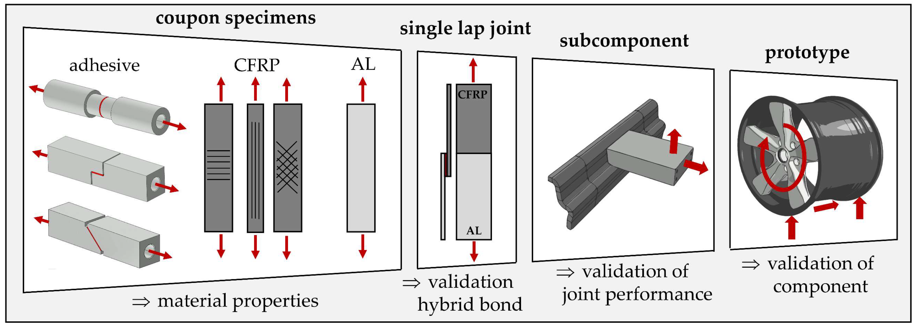
3. Design and Manufacturing of Subcomponent Specimens
3.1. Design of Subcomponent Specimens
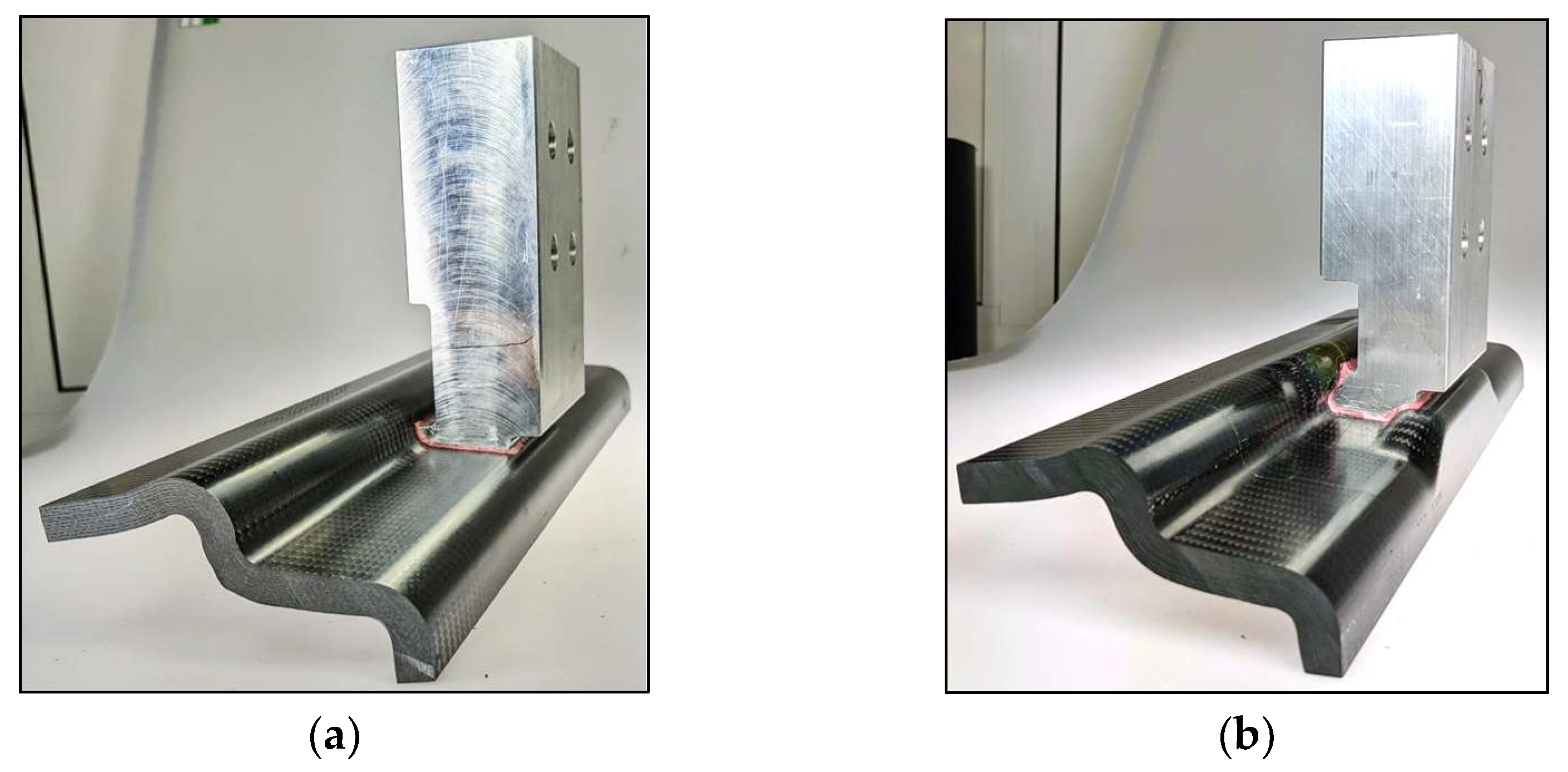
3.1.1. Geometrical Design of Subcomponent Specimen
3.1.2. Comparative Evaluation of the Subcomponent Design
3.2. Manufacturing of Subcomponent Specimens
4. Experimental Analysis of Subcomponent Specimens
- Can the joint withstand the required maximum loading?
- What are the failure modes of the joint?
- How does the “form-fitted joint” perform compared to the “basic joint”?
- What is the influence of temperature on the joint performance?
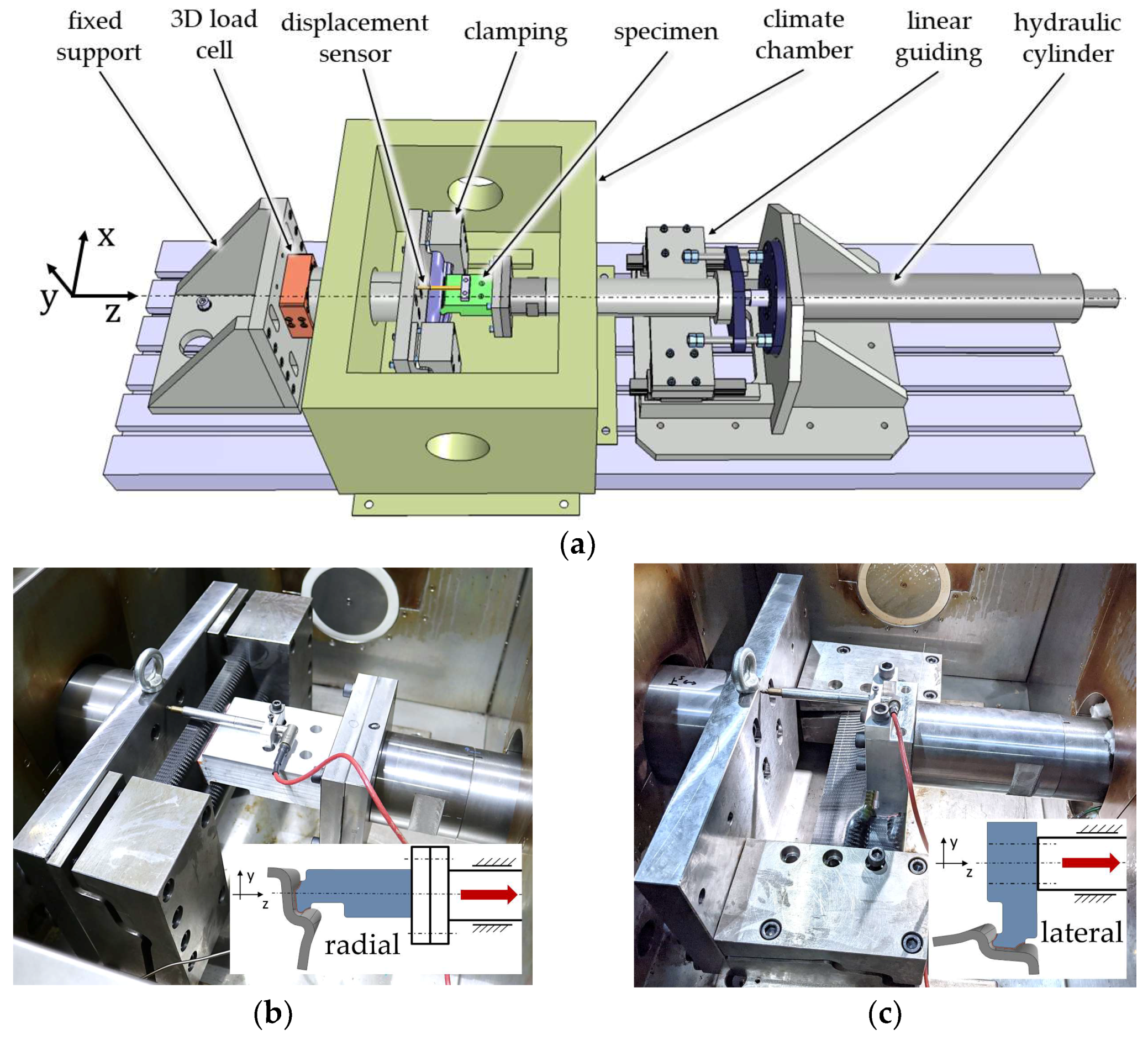
4.1. Test Bench
4.2. Test Program
4.3. Test Results and Discussion
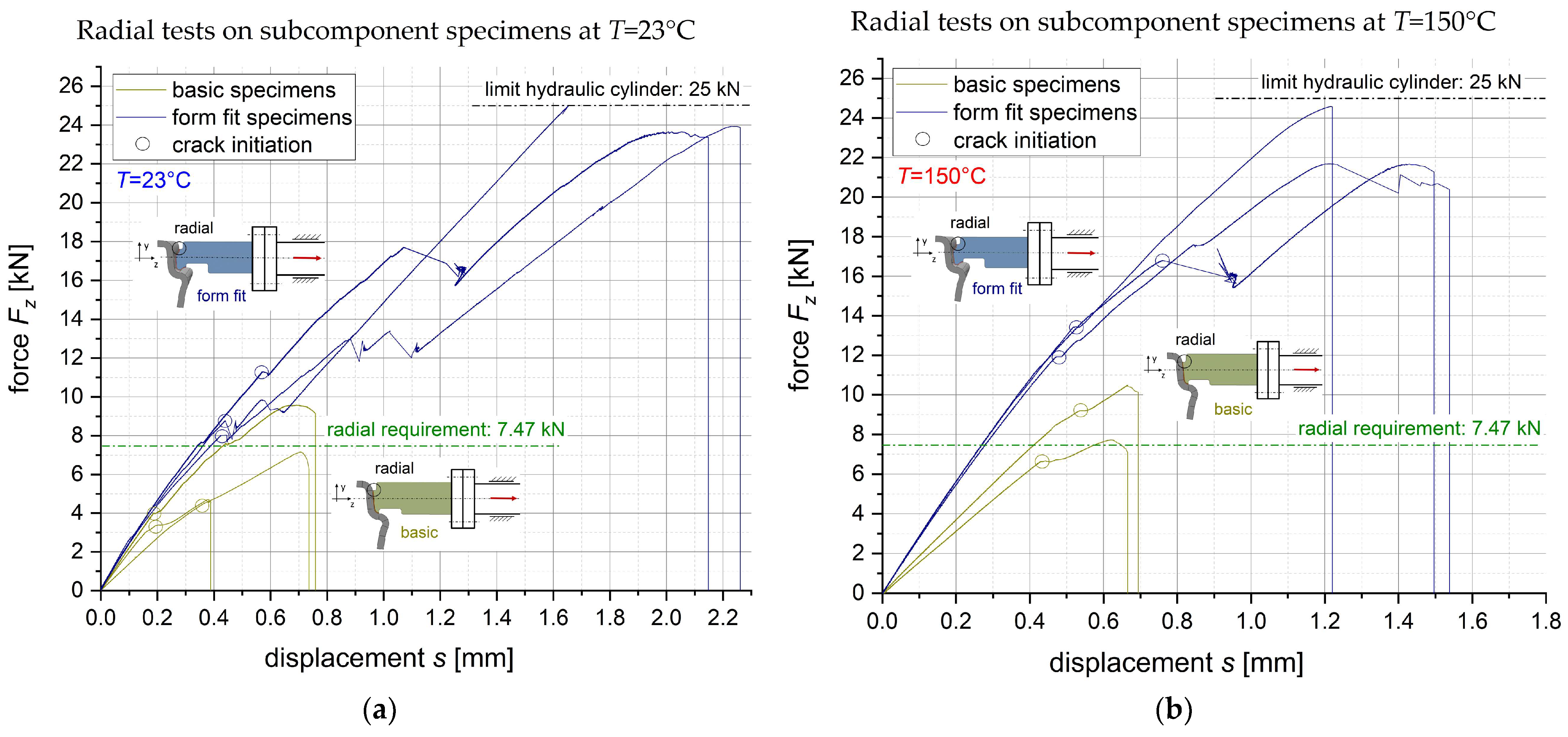
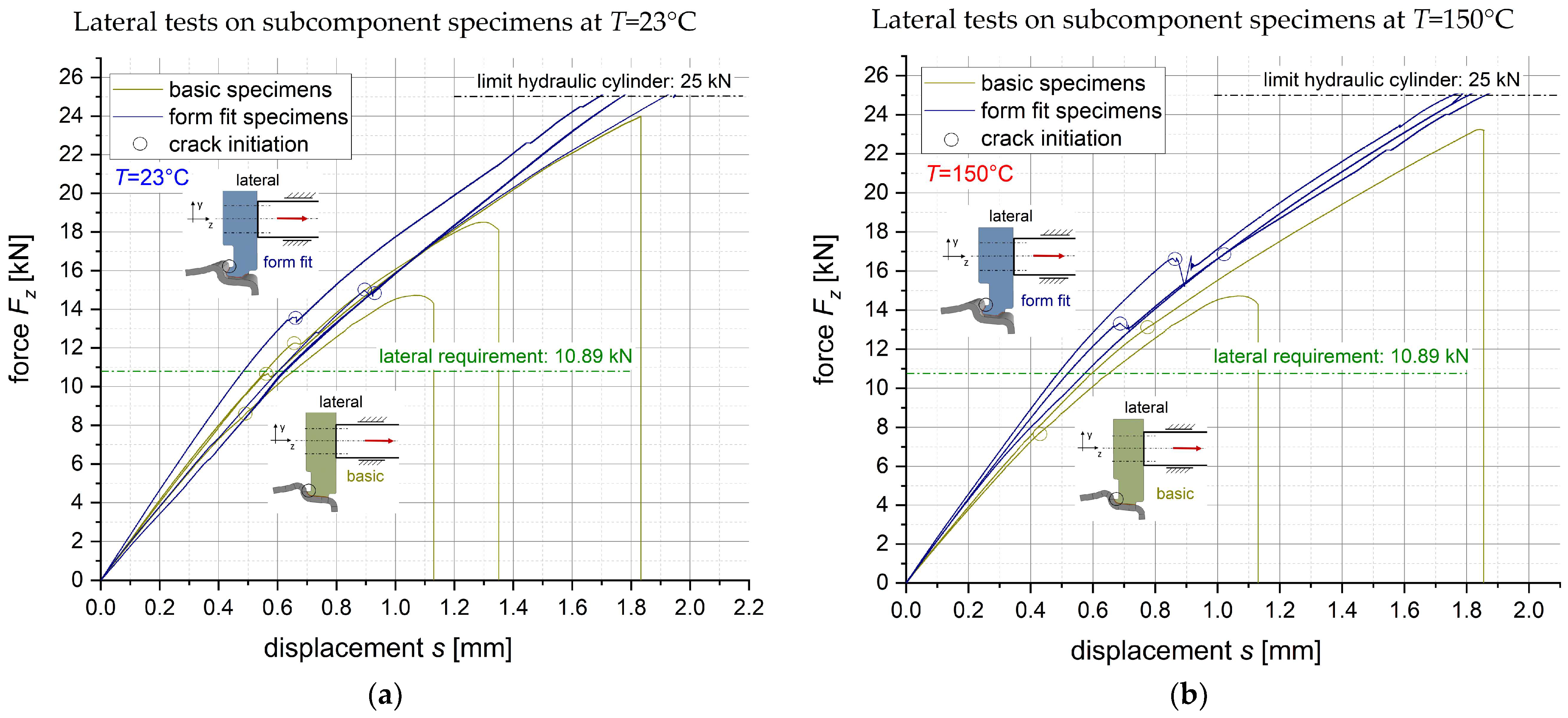
4.3.1. Quasi-Static Tests
4.3.2. Residual Fatigue Tests
5. Conclusions
- The adaption of the fiber layup in the composite rim flange, which reduces the radial force resultants during the thermal load cases significantly;
- The geometrical joint design with a form-fitted radial and lateral support
- The newly developed “form-fitted joint” meets the required critical radial and lateral load and shows significant strength increasement compared to the “basic joint”.
- After a first-crack initiation, the joint shows a distinctive crack propagation phase before final rupture, offering advantages regarding safety design.
- The variation in temperature influences the failure mode of the joint, with a predominant failure of the composite surface layer at 23 °C and a more pronounced cohesive failure within the adhesive layer at 150 °C.
- Residual fatigue tests on the subcomponent specimens indicate good fatigue strength.
- optimization via detailed structural analyses of adhesive and adherend failure;
- optimization of the joint design regarding crack initiation at the edge of the adhesive;
- further evaluation of critical load cases in multiaxial loading at different temperatures with a larger sample size of specimens;
- fatigue tests on wheel prototypes.
Author Contributions
Funding
Acknowledgments
Conflicts of Interest
References
- Hybrid Composite Wheel Reduces Fuel Consumption. Available online: https://www.reinforcedplastics.com/content/products/hybrid-composite-wheel-reduces-fuel-consumption/ (accessed on 4 January 2023).
- Every Gram Counts-M Carbon Compound Wheels for the BMW M4 GTS. Available online: https://www.bmw-m.com/en/topics/magazine-article-pool/every-gram-counts.html (accessed on 4 January 2023).
- Wheels from the Highest Standard-Mubea Performance Wheels. Available online: https://www.mubea.com/en/mubea-performance-wheels (accessed on 4 January 2023).
- CFK-Räder Gehen 2016 in Serie. Available online: https://www.kfz-betrieb.vogel.de/cfk-raeder-gehen-2016-in-serie-a-505562/ (accessed on 4 January 2023).
- Porsche and the Braided Carbon Fiber Wheel. Available online: https://www.compositesworld.com/articles/porsche-and-the-braided-carbon-fiber-wheel (accessed on 4 January 2023).
- Rondina, F.; Taddia, S.; Mazzocchetti, L.; Donati, L.; Minak, G.; Rosenberg, P.; Bedeschi, A.; Dolcini, E. Development of full carbon wheels for sport cars with high-volume technology. Compos. Struct. 2018, 192, 368–378. [Google Scholar] [CrossRef]
- Wacker, J.-D.; Laveuve, D.; Contell Asins, C.; Büter, A. Design of a composite nose wheel for commercial aircraft. IOP Conf. Ser. Mater. Sci. Eng. 2021, 1024, 012018. [Google Scholar] [CrossRef]
- The Fuchsfelge-Forged, Not Cast. Available online: https://www.fuchsfelge.com/en/the-fuchsfelge.html (accessed on 4 January 2023).
- Thyssenkrupp Carbon Components GmbH. Vehicle Wheel Comprising a Wheel Rim and a Wheel Disc. Patent WO2016/037611A1, 17 March 2016.
- Mubea Carbo Tech GmbH. Wheel for a Vehicle. Patent WO2016/066769A1, 6 May 2016.
- GOHybrid-Gestaltung und Optimierung von Hybridverbindungen unter Besonderer Berücksichtigung der Unterschiedlichen Wärmedehnungen der Werkstoffpartner. Available online: https://www.werkstoffplattform-hymat.de/Group/GOHybrid/Pages (accessed on 4 January 2023).
- Da Silva, L.F.M.; Öchsner, A.; Adams, R.D. Handbook of Adhesion, 2nd ed.; Springer: Berlin/Heidelberg, Germany, 2011; pp. 2–4. [Google Scholar]
- Marques, E.A.S.; da Silva, L.F.M.; Banea, M.D.; Carbas, R.J.C. Adhesive Joints for Low- and High-Temperature Use: An Overview. J. Adhes. 2015, 7, 556–585. [Google Scholar] [CrossRef]
- Mubea Carbo Tech GmbH. Heat Shield Structure for a Wheel. Patent WO2016/097159A1, 17 March 2016.
- Carbon Revolution PTY Ltd. Method of Producing Thermally Protected Composite. Patent WO2016/168899A1, 27 October 2016.
- Shang, X.; Marques, E.A.S.; Machado, J.J.M.; Carbas, R.J.C.; Jiang, D.; da Silva, L.F.M. Review on techniques to improve the strength of adhesive joints with composite adherends. Compos. Part B Eng. 2019, 177, 107363. [Google Scholar] [CrossRef]
- Wacker, J.-D.; Tittmann, K.; Koch, I.; Laveuve, D.; Gude, M. Fatigue life analysis of carbon fiber reinforced polymer (CFRP) components in hybrid adhesive joints. Mater. Sci. Eng. Technol. 2021, 52, 1230–1247. [Google Scholar] [CrossRef]
- Qin, G.; Na, J.; Tan, W.; Mu, W.; Ji, J. Failure prediction of adhesively bonded CFRP-Aluminum alloy joints using cohesive zone model with consideration of temperature effect. J. Adhes. 2019, 95, 723–746. [Google Scholar] [CrossRef]
- ASTM D5573−99; Standard Practice for Classifying Failure Modes in Fiber-Reinforced-Plastic (FRP) Joints. ASTM International: West Conshohocken, PA, USA, 2019.
- ISO 11003-2:2019-06; Adhesives-Determination of Shear Behaviour of Structural Adhesives-Part 2: Tensile Test Method Using Thick Adherends. International Organization for Standardization: London, UK, 2019.
- ISO 527-5:2009; Plastics-Determination of Tensile Properties-Part 5: Test Conditions for Unidirectional Fibre-Reinforced Plastic Composites. DIN Deutsches Institut für Normung e.V.: Berlin, Germany, 2009.
- ISO 4587:2003-03; Adhesives-Determination of Tensile Lap-Shear Strength of Rigid-to-Rigid Bonded Assemblies. DIN Deutsches Institut für Normung e.V.: Berlin, Germany, 2003.
- OTTO FUCHS KG. EN AW-6082 nach DIN EN 573 FUCHS AS15/AS11. Product Data Sheet, Rev. 1. Available online: https://www.otto-fuchs.com/fileadmin/user_upload/Infocenter/Werkstoffinformationen/Al-Datenblaetter/AS10-15.pdf (accessed on 4 January 2023).
- WELA Handelsgesellschaft mbH. Kohlefasergewebe WELA GG-245-1000T (AKSA A-38). Product Data Sheet. 2020. Available online: https://wela-hamburg.de/wp-content/uploads/2019/01/datenblatt.pdf (accessed on 4 January 2023).
- WELA Handelsgesellschaft mbH. UD-Kohlefasergewebe WELA GV-303-0500UTFX. Product Data Sheet. 2013. Available online: https://wela-hamburg.de/faserverstaerkungen/ (accessed on 4 January 2023).
- Huntsman Advanced Materials. Araldite® LY 1560/Aradur® 917-1/Accelerator DY 079. Product Data Sheet. 2016. Available online: https://www.huntsman-transportation.com/EN/products/all-products/composite-resin-systems.html/ (accessed on 4 January 2023).


| No. | Load Case | Load | Value | Unit | Sketch |
|---|---|---|---|---|---|
| L1 | straight driving (incl. rough road driving) | max. radial load | 14.02 | kN |  |
| max. lateral load | 3.84 | kN | |||
| L2 | cornering | max. radial load | 10.59 | kN |  |
| max. lateral load | 12.71 | kN | |||
| L3 | braking/ accelerating | max. torsional moment | ±1.91 | kNm |  |
| L4.1 | thermal loading | max. temperature joint | 150 | °C |  |
| L4.2 | min. temperature joint | −40 | °C | ||
| L4.3 | max. temperature wheel rim | 200 | °C |
| Carbon/Epoxy Composite Orthotropic Ply WELA GG-245 [24]/ Araldite® LY 1560 [26] | Carbon/Epoxy Composite Unidirectional Ply WELA GV-303-0500 [25]/ Araldite® LY 1560 [26] | Aluminum Alloy, Isotropic EN AW-6082 T6 [23] | Adhesive, Isotropic BETAMATE™ HTG | ||||||||
|---|---|---|---|---|---|---|---|---|---|---|---|
| Property | Value | Unit | Property | Value | Unit | Property | Value | Unit | Property | Value | Unit |
| 66.39 1 | GPa | 124.24 1 | GPa | 70.00 3 | GPa | 2.54 1 | GPa | ||||
| 66.39 1 | GPa | 8.78 1 | GPa | 0.33 3 | - | 0.40 4 | - | ||||
| 15.76 1 | GPa | 4.70 2 | GPa | 23.4 3 | /K | 40.0 4 | /K | ||||
| 0.30 1 | - | 0.27 2 | - | ||||||||
| 2.2 2 | /K | −0.5 2 | /K | ||||||||
| 2.2 2 | /K | 30.0 2 | /K | ||||||||
| No. | Load Case | Spoke Position | Force Resultants | Moment Resultants | ||||
|---|---|---|---|---|---|---|---|---|
| (kN) | (kN) | (kN) | (Nm) | (Nm) | (Nm) | |||
| L1 | straight driving | 126° | 0.87 | −3.67 | −2.84 | 88 | 193 | −205 |
| 180° | 0.08 | −8.39 | −6.64 | 43 | 8 | −5 | ||
| 234° | −0.87 | −3.67 | −2.84 | 88 | −193 | 205 | ||
| L2 | cornering | 126° | 2.50 | −5.83 | −6.10 | 171 | 293 | −178 |
| 180° | 0.13 | −9.25 | −10.89 | 136 | 11 | −3 | ||
| 234° | −2.50 | −5.83 | −6.10 | 171 | −293 | 178 | ||
| L3 | braking | all pos. | −1.52 | 0 | 0 | 0 | −78 | 9 |
| L4.1 | 23 to 150 °C | all pos. | 0 | −28.61 | 0.02 | −67 | 0 | 0 |
| L4.2 | 23 to −40 °C | all pos. | 0 | 14.08 | −0.01 | 33 | 0 | 0 |
| No. | Load Case | Spoke Position | Force Resultants | Moment Resultants | ||||
|---|---|---|---|---|---|---|---|---|
| (kN) | (kN) | (kN) | (Nm) | (Nm) | (Nm) | |||
| L4.1 * | 23 °C to 150 °C | all pos. | 0 | −15.18 | −0.10 | 53 | 0 | 0 |
| L4.2 * | 23 °C to −40 °C | all pos. | 0 | 7.47 | 0.05 | 26 | 0 | 0 |
| Model | Load Case | Force Resultants | Moment Resultants | ||||
|---|---|---|---|---|---|---|---|
| (kN) | (kN) | (kN) | (Nm) | (Nm) | (Nm) | ||
| subcomponent | radial loading: 7.47 kN | 0 | 7.47 | 0.09 | 5 | 0 | 0 |
| wheel | thermal: 23 °C to −40 °C | 0 | 7.47 | 0.05 | 26 | 0 | 0 |
| subcomponent | lateral loading: 10.89 kN | 0.20 | −0.86 | −10.89 | 63 | 0 | 0 |
| wheel | cornering: 180° position | 0.13 | −9.25 | −10.89 | 136 | 11 | −3 |
| Specimens | Type of Test | Load Case | Number of Specimens | |
|---|---|---|---|---|
| 23 °C | 150 °C | |||
“basic specimen” | quasi-static test | radial | 3 | 2 |
| lateral | 3 | 2 | ||
“form-fitted specimen” | quasi-static test | radial | 3 | 3 |
| lateral | 3 | 3 | ||
| residual fatigue test | radial | 1 | ||
| lateral | 1 | |||
| T = 23 °C | T = 150 °C | |
|---|---|---|
| basic joint | 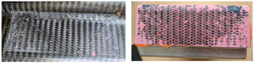 | 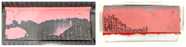 |
| form-fitted joint | 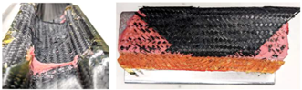 |  |
| T = 23 °C | T = 150 °C | |
|---|---|---|
| basic joint |  |  |
Disclaimer/Publisher’s Note: The statements, opinions and data contained in all publications are solely those of the individual author(s) and contributor(s) and not of MDPI and/or the editor(s). MDPI and/or the editor(s) disclaim responsibility for any injury to people or property resulting from any ideas, methods, instructions or products referred to in the content. |
© 2023 by the authors. Licensee MDPI, Basel, Switzerland. This article is an open access article distributed under the terms and conditions of the Creative Commons Attribution (CC BY) license (https://creativecommons.org/licenses/by/4.0/).
Share and Cite
Wacker, J.-D.; Kloska, T.; Linne, H.; Decker, J.; Janes, A.; Huxdorf, O.; Bose, S. Design and Experimental Analysis of an Adhesive Joint for a Hybrid Automotive Wheel. Processes 2023, 11, 819. https://doi.org/10.3390/pr11030819
Wacker J-D, Kloska T, Linne H, Decker J, Janes A, Huxdorf O, Bose S. Design and Experimental Analysis of an Adhesive Joint for a Hybrid Automotive Wheel. Processes. 2023; 11(3):819. https://doi.org/10.3390/pr11030819
Chicago/Turabian StyleWacker, Jens-David, Tobias Kloska, Hannah Linne, Julia Decker, Andre Janes, Oliver Huxdorf, and Sven Bose. 2023. "Design and Experimental Analysis of an Adhesive Joint for a Hybrid Automotive Wheel" Processes 11, no. 3: 819. https://doi.org/10.3390/pr11030819
APA StyleWacker, J.-D., Kloska, T., Linne, H., Decker, J., Janes, A., Huxdorf, O., & Bose, S. (2023). Design and Experimental Analysis of an Adhesive Joint for a Hybrid Automotive Wheel. Processes, 11(3), 819. https://doi.org/10.3390/pr11030819