
Utilization of Carbon Dioxide via Catalytic Hydrogenation Processes during Steam-Based Enhanced Oil Recovery

 ,
,  ,
,  ,
, 

Abstract
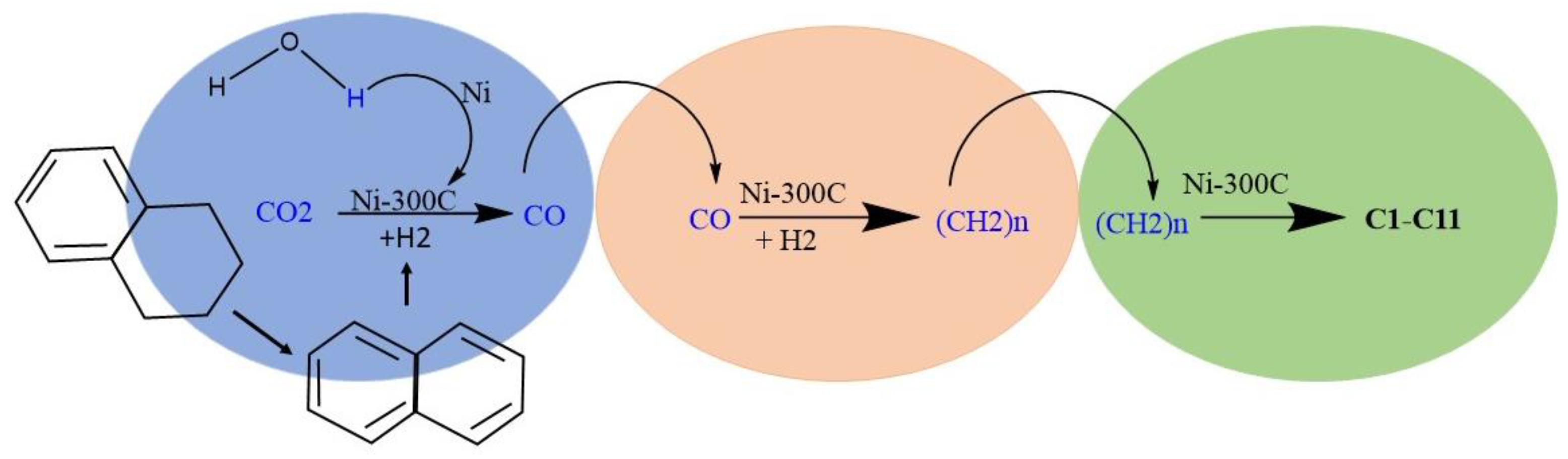
1. Introduction
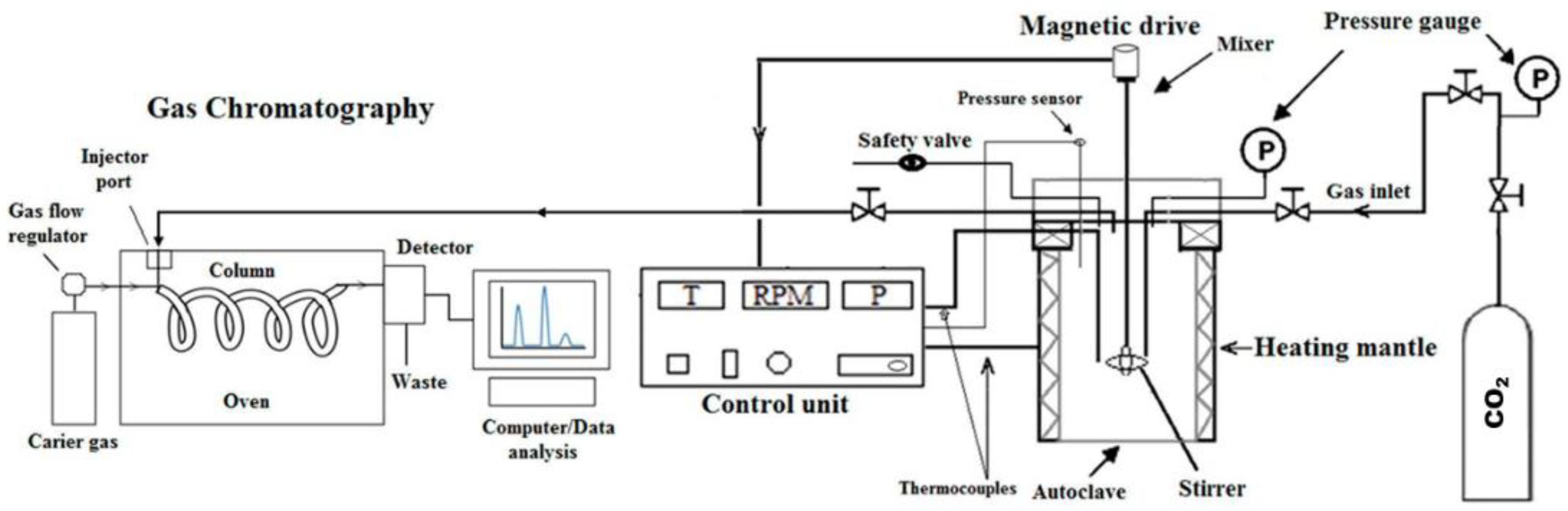
2. Materials and Methods
3. Results and Discussion
3.1. The Composition of Evolved Gases
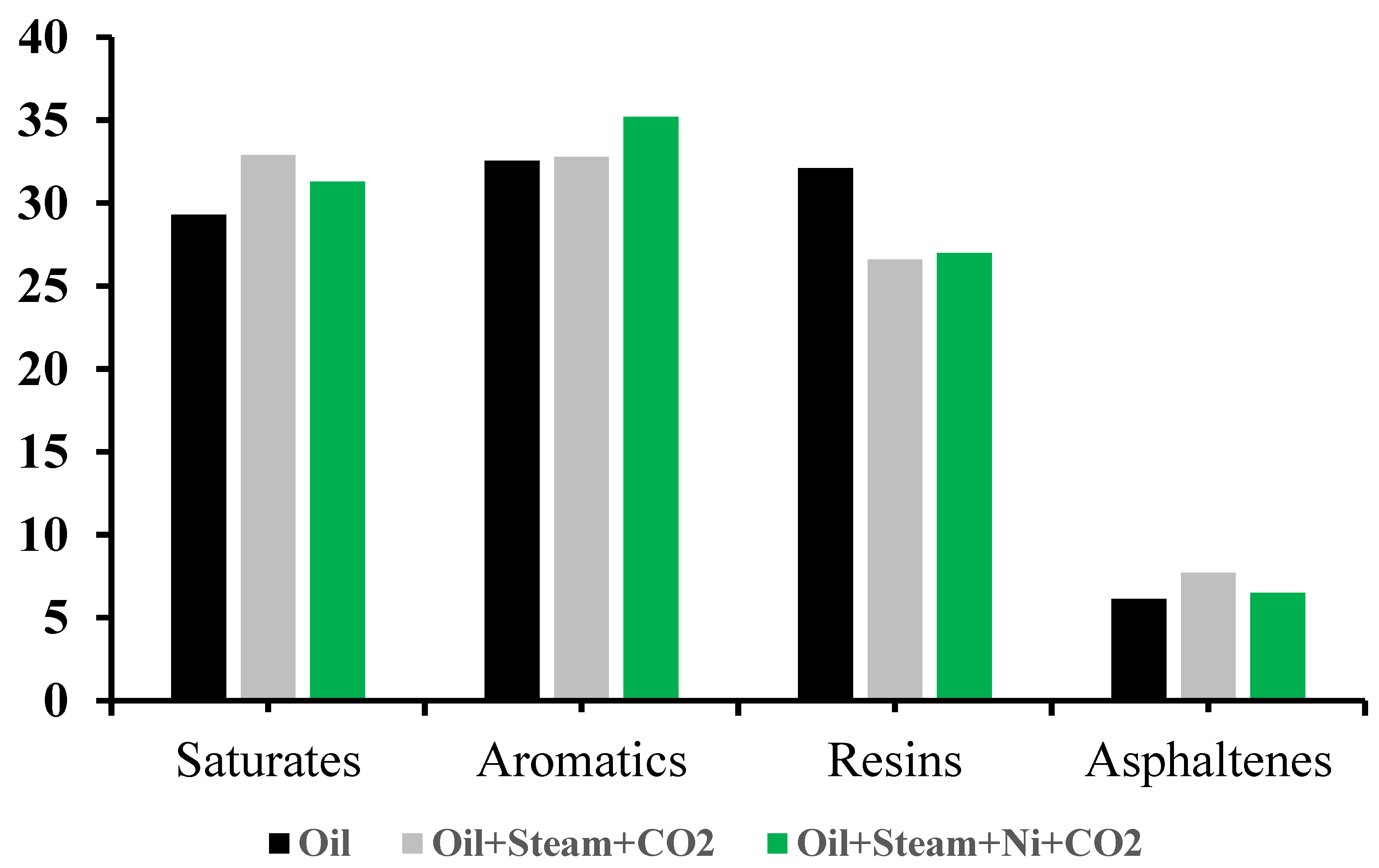
3.2. The Group Composition of Upgraded Crude Oil
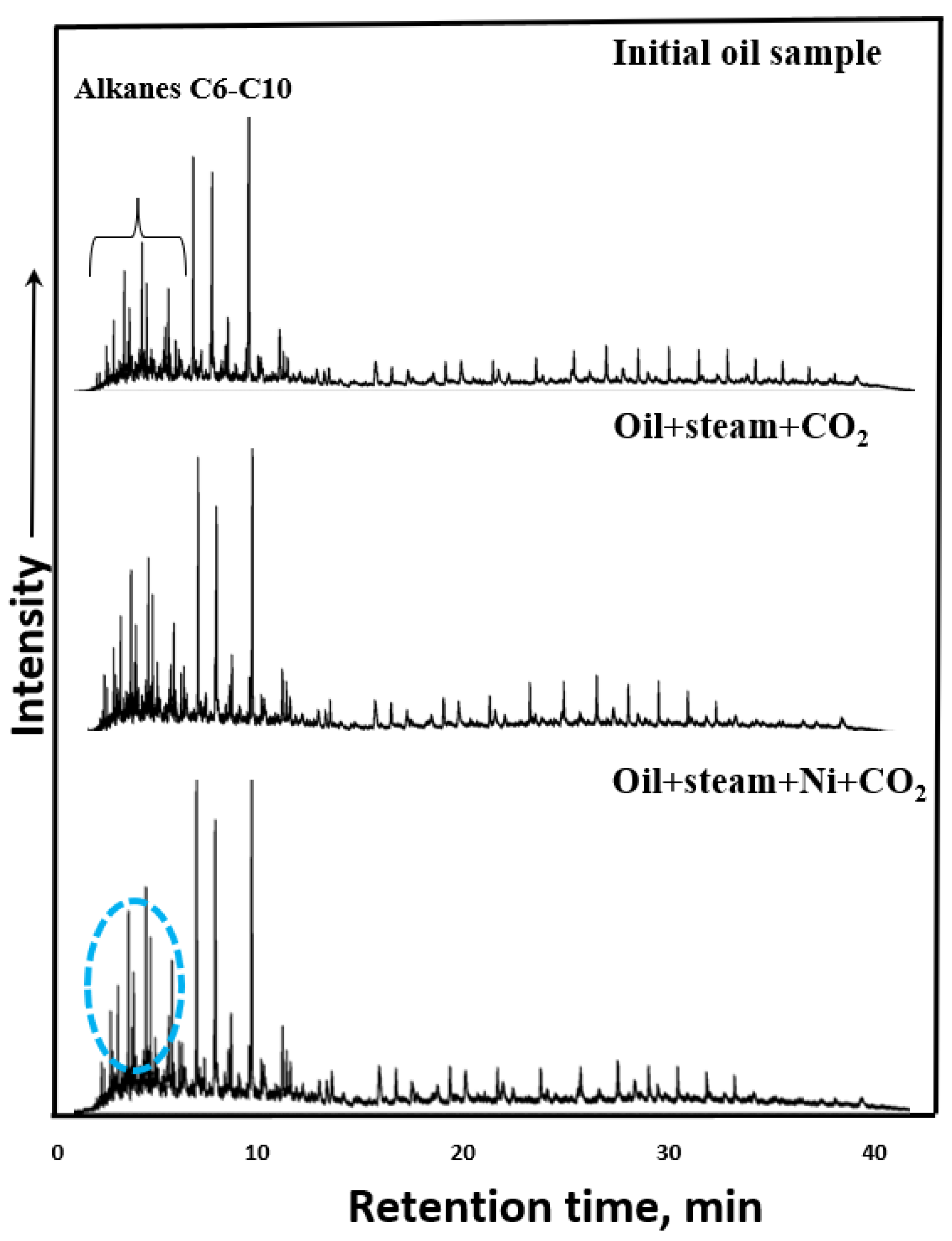
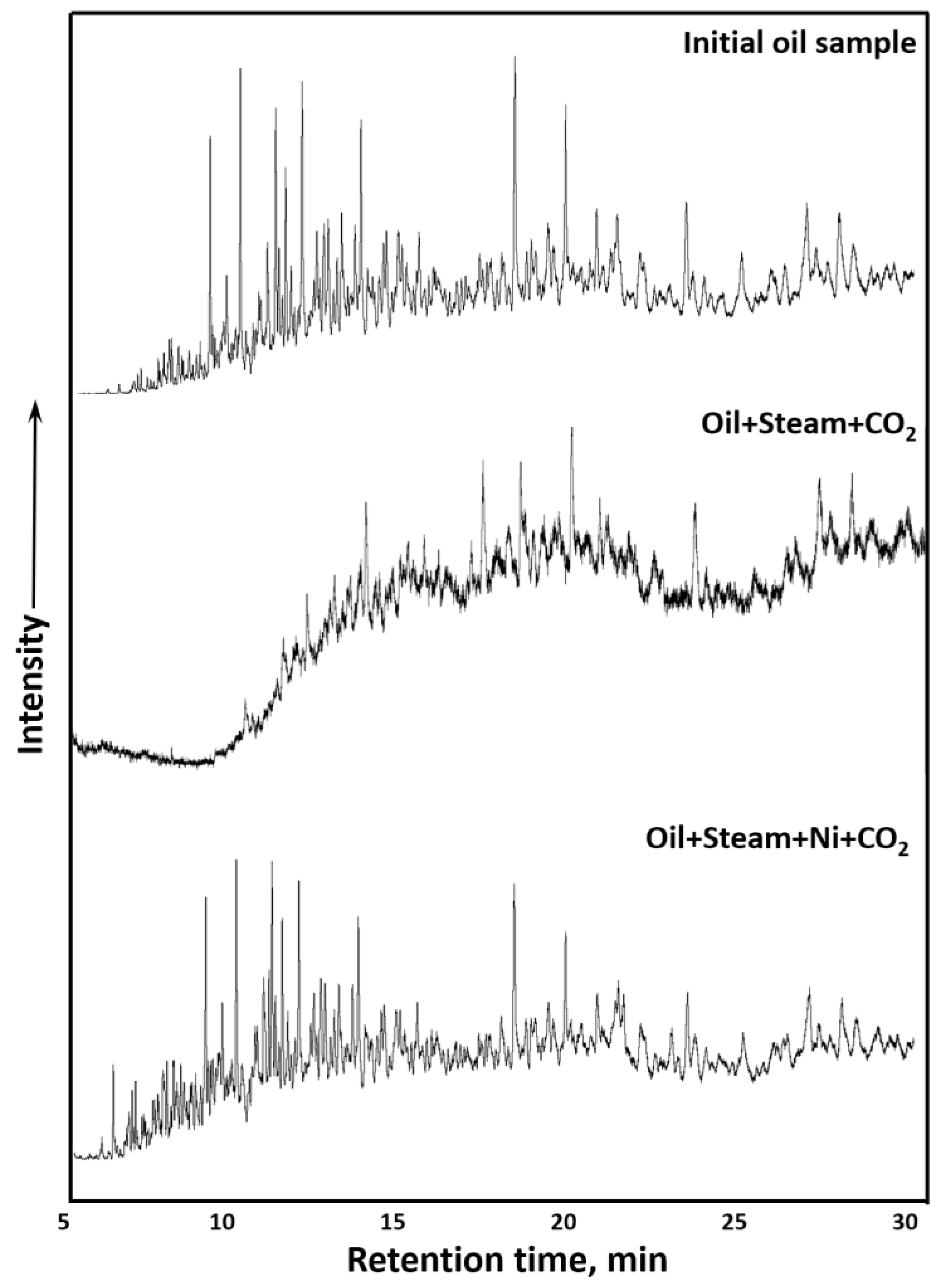
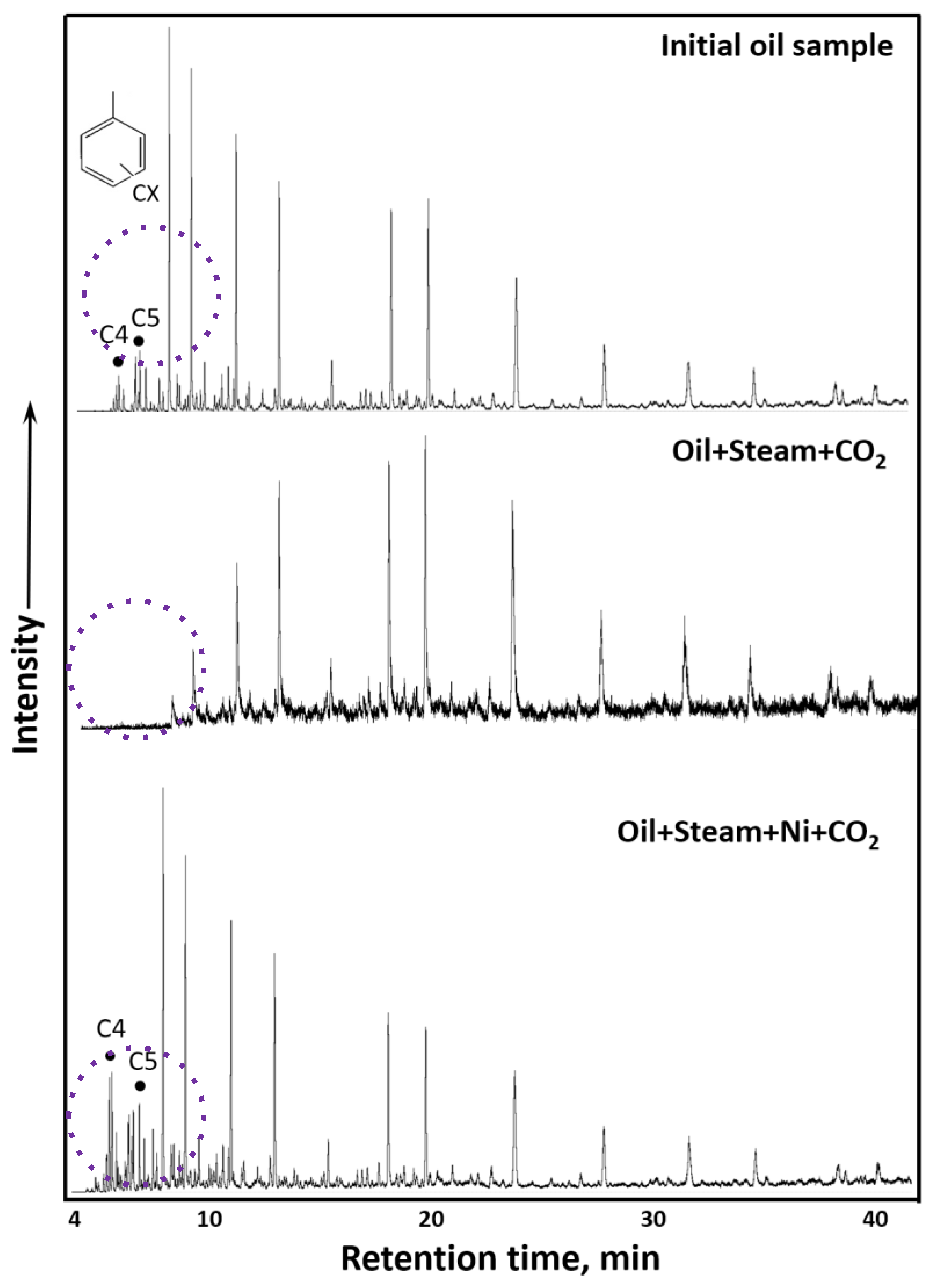
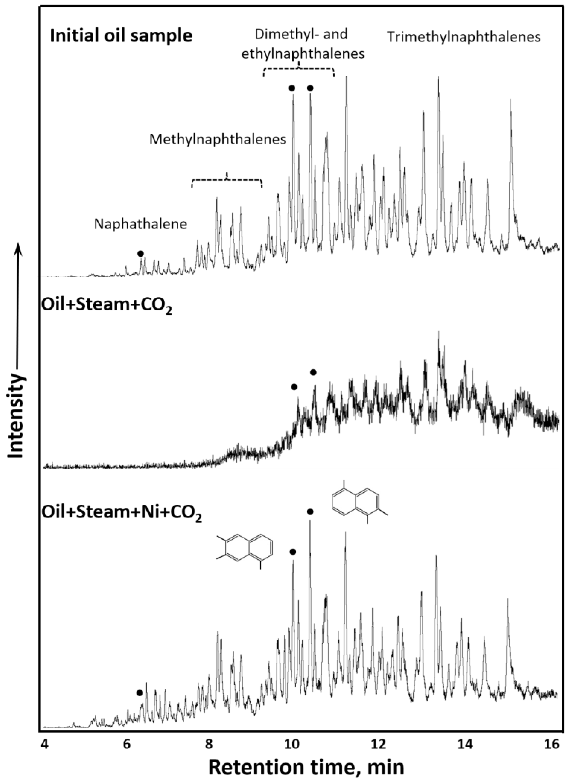
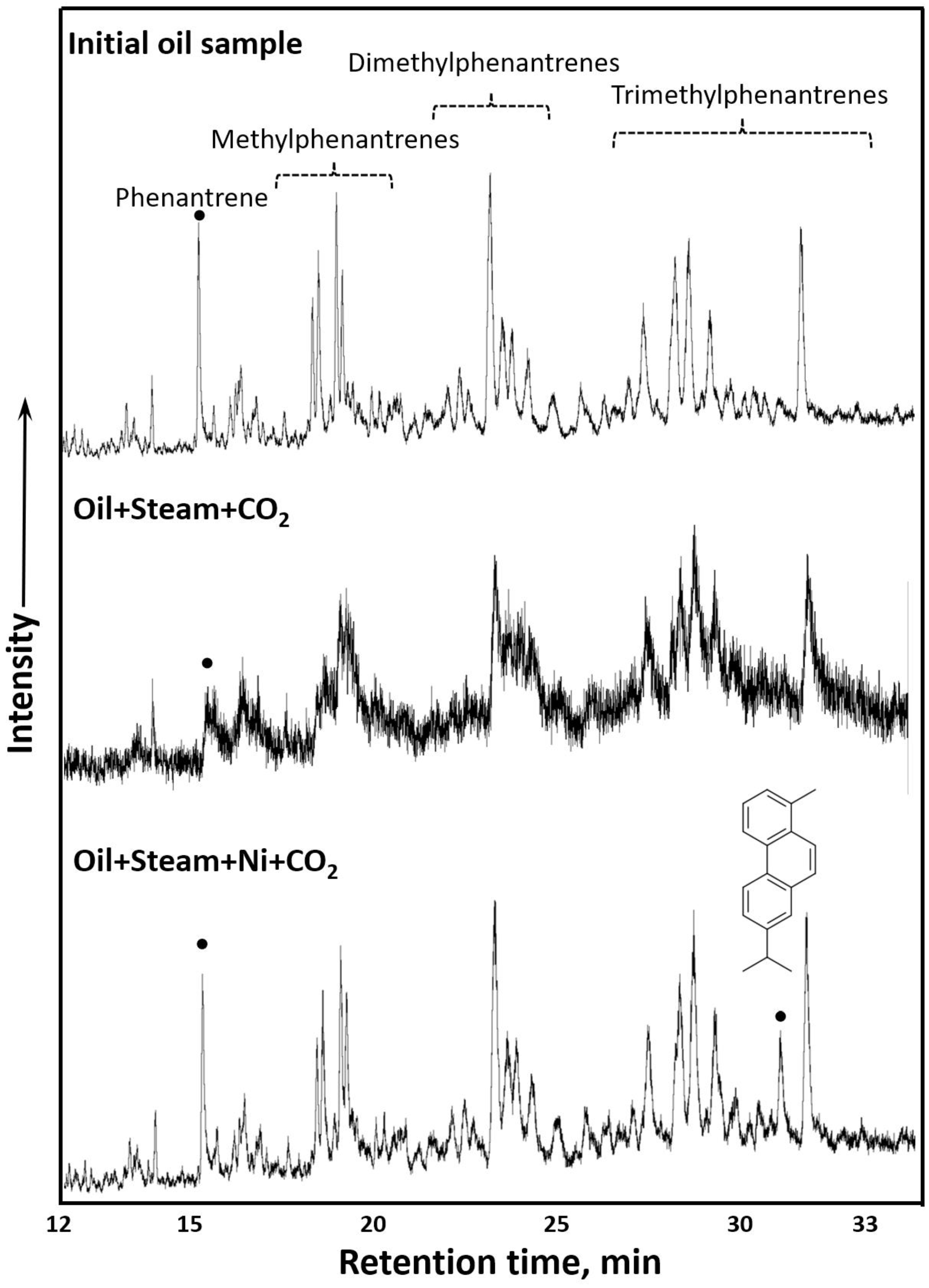
3.3. GC-MS Results of Saturates and Aromatics
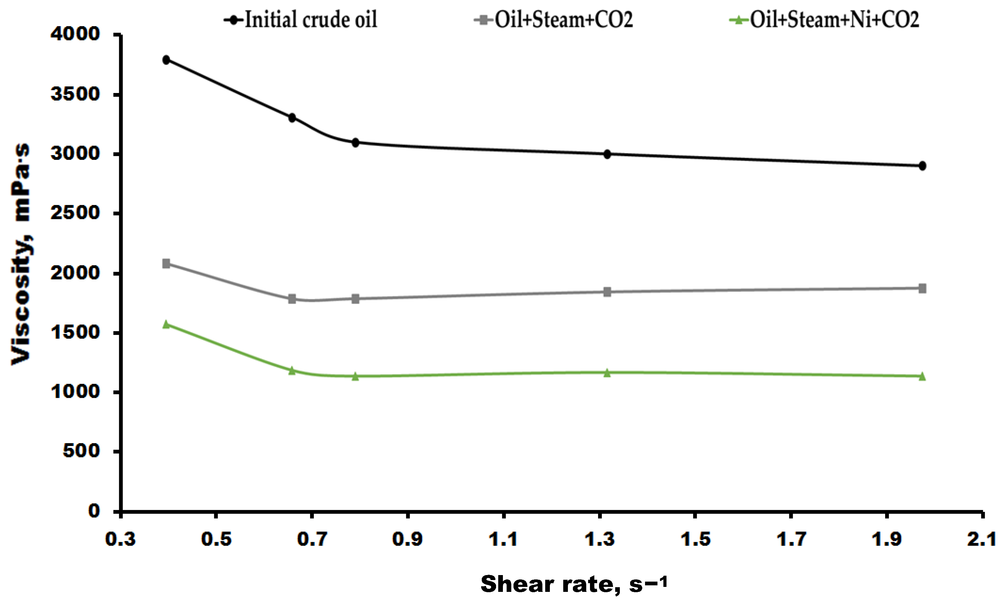
3.4. Viscosity Measurements of Oil Samples
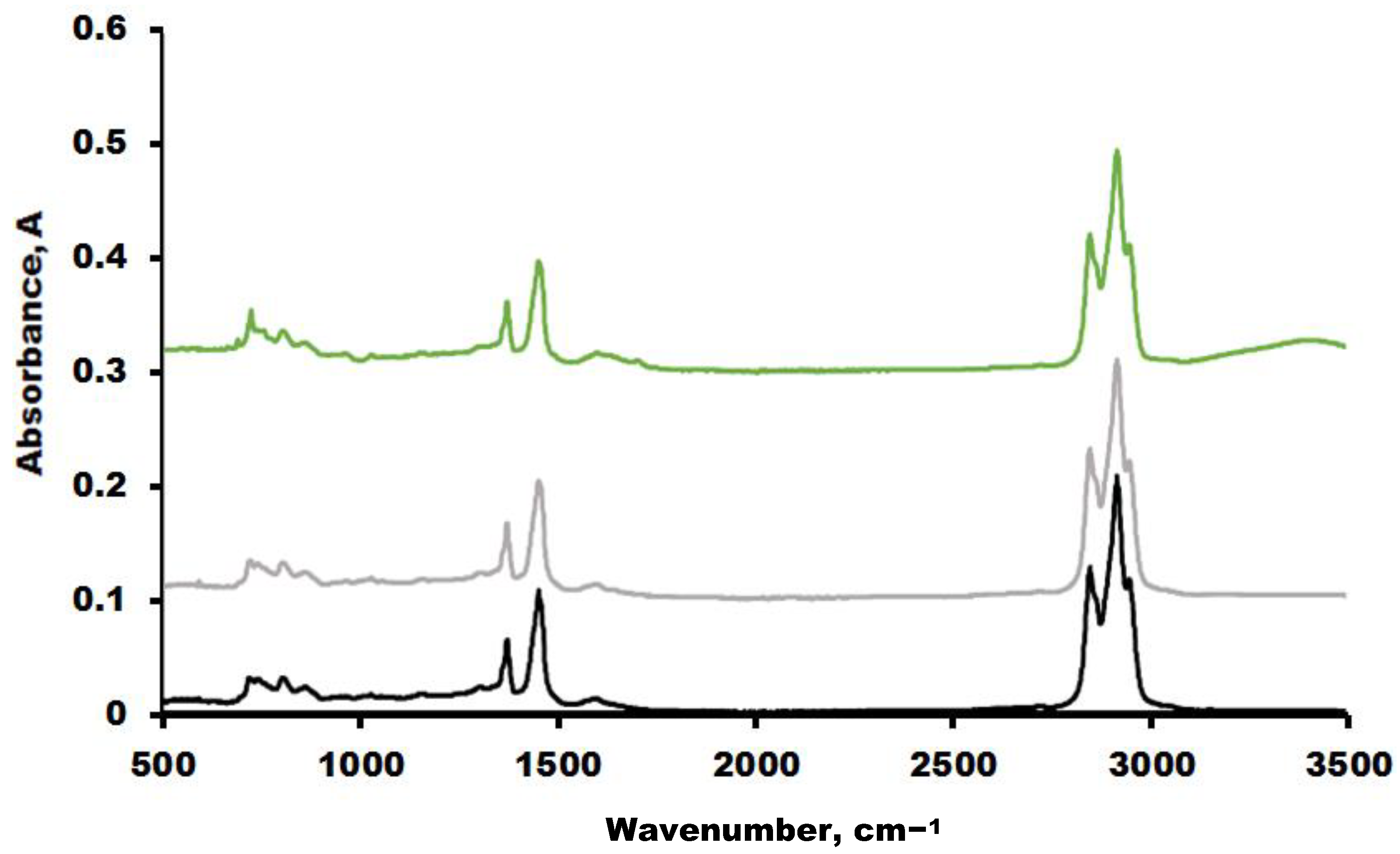
3.5. FTIR Spectroscopy Results of Oil Samples
4. Conclusions
Author Contributions
Funding
Institutional Review Board Statement
Informed Consent Statement
Data Availability Statement
Conflicts of Interest
References
- Rogelj, J.; den Elzen, M.; Höhne, N.; Fransen, T.; Fekete, H.; Winkler, H.; Schaeffer, R.; Sha, F.; Riahi, K.; Meinshausen, M. Paris Agreement Climate Proposals Need a Boost to Keep Warming Well below 2 C. Nature 2016, 534, 631–639. [Google Scholar] [CrossRef] [PubMed]
- Tarkowski, R.; Uliasz-Misiak, B.; Tarkowski, P. Storage of Hydrogen, Natural Gas, and Carbon Dioxide–Geological and Legal Conditions. Int. J. Hydrogen Energy 2021, 46, 20010–20022. [Google Scholar] [CrossRef]
- Raza, A.; Gholami, R.; Rezaee, R.; Rasouli, V.; Rabiei, M. Significant Aspects of Carbon Capture and Storage—A Review. Petroleum 2019, 5, 335–340. [Google Scholar] [CrossRef]
- Aminu, M.D.; Nabavi, S.A.; Rochelle, C.A.; Manovic, V. A Review of Developments in Carbon Dioxide Storage. Appl. Energy 2017, 208, 1389–1419. [Google Scholar] [CrossRef]
- Alcorn, Z.P.; Fredriksen, S.B.; Sharma, M.; Rognmo, A.U.; Føyen, T.L.; Fernø, M.A.; Graue, A. An Integrated Carbon-Dioxide-Foam Enhanced-Oil-Recovery Pilot Program with Combined Carbon Capture, Utilization, and Storage in an Onshore Texas Heterogeneous Carbonate Field. SPE Reserv. Eval. Eng. 2019, 22, 1449–1466. [Google Scholar] [CrossRef]
- Bondor, P.L. Applications of Carbon Dioxide in Enhanced Oil Recovery. Energy Convers. Manag. 1992, 33, 579–586. [Google Scholar] [CrossRef]
- Blunt, M.; Fayers, F.J.; Orr, F.M., Jr. Carbon Dioxide in Enhanced Oil Recovery. Energy Convers. Manag. 1993, 34, 1197–1204. [Google Scholar] [CrossRef]
- Wei, J.; Zhou, J.; Li, J.; Zhou, X.; Dong, W.; Cheng, Z. Experimental Study on Oil Recovery Mechanism of CO2 Associated Enhancing Oil Recovery Methods in Low Permeability Reservoirs. J. Pet. Sci. Eng. 2021, 197, 108047. [Google Scholar] [CrossRef]
- Gunasekar, G.H.; Park, K.; Jung, K.-D.; Yoon, S. Recent Developments in the Catalytic Hydrogenation of CO2 to Formic Acid/Formate Using Heterogeneous Catalysts. Inorg. Chem. Front 2016, 3, 882–895. [Google Scholar] [CrossRef]
- Zhou, G.; Dai, B.; Xie, H.; Zhang, G.; Xiong, K.; Zheng, X. CeCu Composite Catalyst for CO Synthesis by Reverse Water–Gas Shift Reaction: Effect of Ce/Cu Mole Ratio. J. CO2 Util. 2017, 21, 292–301. [Google Scholar] [CrossRef]
- Lee, M.-D.; Lee, J.-F.; Chang, C.-S. Hydrogenation of Carbon Dioxide on Unpromoted and Potassium-Promoted Iron Catalysts. Bull. Chem. Soc. Jpn. 1989, 62, 2756–2758. [Google Scholar] [CrossRef]
- Prieto, G. Carbon Dioxide Hydrogenation into Higher Hydrocarbons and Oxygenates: Thermodynamic and Kinetic Bounds and Progress with Heterogeneous and Homogeneous Catalysis. ChemSusChem 2017, 10, 1056–1070. [Google Scholar] [CrossRef] [PubMed]
- Nakayama, T.; Ichikuni, N.; Sato, S.; Nozaki, F. Ni/MgO Catalyst Prepared Using Citric Acid for Hydrogenation of Carbon Dioxide. Appl. Catal. A Gen. 1997, 158, 185–199. [Google Scholar] [CrossRef]
- Ayodele, O.B. Eliminating Reverse Water Gas Shift Reaction in CO2 Hydrogenation to Primary Oxygenates over MFI-Type Zeolite Supported Cu/ZnO Nanocatalysts. J. CO2 Util. 2017, 20, 368–377. [Google Scholar] [CrossRef]
- Su, X.; Yang, X.; Zhao, B.; Huang, Y. Designing of Highly Selective and High-Temperature Endurable RWGS Heterogeneous Catalysts: Recent Advances and the Future Directions. J. Energy Chem. 2017, 26, 854–867. [Google Scholar] [CrossRef]
- Ma, J.; Sun, N.; Zhang, X.; Zhao, N.; Xiao, F.; Wei, W.; Sun, Y. A Short Review of Catalysis for CO2 Conversion. Catal. Today 2009, 148, 221–231. [Google Scholar] [CrossRef]
- Guo, R.; Fu, W.; Qu, L.; Li, Y.; Yuan, W.; Chen, G. Methanol-Enhanced Fe (III) Oleate-Catalyzed Aquathermolysis of Heavy Oil. Processes 2022, 10, 1956. [Google Scholar] [CrossRef]
- Kattel, S.; Liu, P.; Chen, J.G. Tuning Selectivity of CO2 Hydrogenation Reactions at the Metal/Oxide Interface. J. Am. Chem. Soc. 2017, 139, 9739–9754. [Google Scholar] [CrossRef]
- Ma, L.; Zhang, S.; Zhang, X.; Dong, S.; Yu, T.; Slaný, M.; Chen, G. Enhanced Aquathermolysis of Heavy Oil Catalysed by Bentonite Supported Fe (III) Complex in the Present of Ethanol. J. Chem. Technol. Biotechnol. 2022, 97, 1128–1137. [Google Scholar] [CrossRef]
- Beuls, A.; Swalus, C.; Jacquemin, M.; Heyen, G.; Karelovic, A.; Ruiz, P. Methanation of CO2: Further Insight into the Mechanism over Rh/γ-Al2O3 Catalyst. Appl. Catal. B 2012, 113, 2–10. [Google Scholar] [CrossRef]
- da Silva, D.C.D.; Letichevsky, S.; Borges, L.E.P.; Appel, L.G. The Ni/ZrO2 Catalyst and the Methanation of CO and CO2. Int. J. Hydrogen Energy 2012, 37, 8923–8928. [Google Scholar] [CrossRef]
- Razzaq, R.; Li, C.; Usman, M.; Suzuki, K.; Zhang, S. A Highly Active and Stable Co4N/γ-Al2O3 Catalyst for CO and CO2 Methanation to Produce Synthetic Natural Gas (SNG). Chem. Eng. J. 2015, 262, 1090–1098. [Google Scholar] [CrossRef]
- Pastor-Pérez, L.; Baibars, F.; le Sache, E.; Arellano-Garcia, H.; Gu, S.; Reina, T.R. CO2 Valorisation via Reverse Water-Gas Shift Reaction Using Advanced Cs Doped Fe-Cu/Al2O3 Catalysts. J. CO2 Util. 2017, 21, 423–428. [Google Scholar] [CrossRef]
- Zhu, M.; Wachs, I.E. Resolving the Reaction Mechanism for H2 Formation from High-Temperature Water–Gas Shift by Chromium–Iron Oxide Catalysts. ACS Catal. 2016, 6, 2827–2830. [Google Scholar] [CrossRef]
- Loiland, J.A.; Wulfers, M.J.; Marinkovic, N.S.; Lobo, R.F. Fe/γ-Al2O3 and Fe–K/γ-Al2O3 as Reverse Water-Gas Shift Catalysts. Catal. Sci. Technol. 2016, 6, 5267–5279. [Google Scholar] [CrossRef]
- Park, S.-W.; Joo, O.-S.; Jung, K.-D.; Kim, H.; Han, S.-H. ZnO/Cr2O3 Catalyst for Reverse-Water-Gas-Shift Reaction of CAMERE Process. Korean J. Chem. Eng. 2000, 17, 719–722. [Google Scholar] [CrossRef]
- Feng, K.; Tian, J.; Guo, M.; Wang, Y.; Wang, S.; Wu, Z.; Zhang, J.; He, L.; Yan, B. Experimentally Unveiling the Origin of Tunable Selectivity for CO2 Hydrogenation over Ni-Based Catalysts. Appl. Catal. B 2021, 292, 120191. [Google Scholar] [CrossRef]
- Sengupta, S.; Jha, A.; Shende, P.; Maskara, R.; Das, A.K. Catalytic Performance of Co and Ni Doped Fe-Based Catalysts for the Hydrogenation of CO2 to CO via Reverse Water-Gas Shift Reaction. J. Environ. Chem. Eng. 2019, 7, 102911. [Google Scholar] [CrossRef]
- Wang, C.; Tian, Y.; Wu, R.; Li, H.; Yao, B.; Zhao, Y.; Xiao, T. Bimetallic Synergy Effects of Phyllosilicate-Derived NiCu@ SiO2 Catalysts for 1,4-Butynediol Direct Hydrogenation to 1,4-Butanediol. ChemCatChem 2019, 11, 4777–4787. [Google Scholar] [CrossRef]
- Vakhin, A.V.; Aliev, F.A.; Mukhamatdinov, I.I.; Sitnov, S.A.; Sharifullin, A.V.; Kudryashov, S.I.; Afanasiev, I.S.; Petrashov, O.V.; Nurgaliev, D.K. Catalytic Aquathermolysis of Boca de Jaruco Heavy Oil with Nickel-Based Oil-Soluble Catalyst. Processes 2020, 8, 532. [Google Scholar] [CrossRef]
- Al-Muntaser, A.A.; Varfolomeev, M.A.; Suwaid, M.A.; Feoktistov, D.A.; Yuan, C.; Klimovitskii, A.E.; Gareev, B.I.; Djimasbe, R.; Nurgaliev, D.K.; Kudryashov, S.I. Hydrogen Donating Capacity of Water in Catalytic and Non-Catalytic Aquathermolysis of Extra-Heavy Oil: Deuterium Tracing Study. Fuel 2021, 283, 118957. [Google Scholar] [CrossRef]
- Sitnov, S.A.; Mukhamatdinov, I.I.; Vakhin, A.V.; Ivanova, A.G.; Voronina, E.V. Composition of Aquathermolysis Catalysts Forming in Situ from Oil-Soluble Catalyst Precursor Mixtures. J. Pet. Sci. Eng. 2018, 169, 44–50. [Google Scholar] [CrossRef]


| Model System * | Temp., C | Gas Yield (vol.%) | ||||||||||
|---|---|---|---|---|---|---|---|---|---|---|---|---|
| C1 | C2 | C3 | C4 | H2 | CO2 | H2S | CO | O2 | N2 | Unidentified HC Gases | ||
| 2 | 300 | 1.44 | 0.42 | 0.33 | 0.16 | 0.13 | 94.25 | 1.29 | - | 0.01 | 0.67 | 1.3 |
| 3 | 300 | 0.46 | 0.46 | 0.42 | 0.13 | 0.18 | 89.26 | 0.32 | 0.25 | 0.87 | 4.68 | 2.97 |
| Samples | Oil | Oil + Steam + CO2 | Oil + Steam + Ni + CO2 |
|---|---|---|---|
| n-alkanes C10–C20 | 6.30 | 10.93 | 11.80 |
| n-alkanes C21–C34 | 20.80 | 17.96 | 19.12 |
| isoalkanes | 72.90 | 71.11 | 69.08 |
| * Spectral Coefficients | Subject of Research | ||
|---|---|---|---|
| Initial Crude Oil | Oil + Steam + CO2 | Oil + Steam + Ni + CO2 | |
| C1 | 0.43 | 0.43 | 0.44 |
| C2 | 0.03 | 0.05 | 0.12 |
| C3 | 0.62 | 0.62 | 0.63 |
| C4 | 6.80 | 6.54 | 5.31 |
| C5 | 0.17 | 0.20 | 0.18 |
Publisher’s Note: MDPI stays neutral with regard to jurisdictional claims in published maps and institutional affiliations. |
© 2022 by the authors. Licensee MDPI, Basel, Switzerland. This article is an open access article distributed under the terms and conditions of the Creative Commons Attribution (CC BY) license (https://creativecommons.org/licenses/by/4.0/).
Share and Cite
Aliev, F.; Mirzaev, O.; Kholmurodov, T.; Slavkina, O.; Vakhin, A. Utilization of Carbon Dioxide via Catalytic Hydrogenation Processes during Steam-Based Enhanced Oil Recovery. Processes 2022, 10, 2306. https://doi.org/10.3390/pr10112306
Aliev F, Mirzaev O, Kholmurodov T, Slavkina O, Vakhin A. Utilization of Carbon Dioxide via Catalytic Hydrogenation Processes during Steam-Based Enhanced Oil Recovery. Processes. 2022; 10(11):2306. https://doi.org/10.3390/pr10112306
Chicago/Turabian StyleAliev, Firdavs, Oybek Mirzaev, Temurali Kholmurodov, Olga Slavkina, and Alexey Vakhin. 2022. "Utilization of Carbon Dioxide via Catalytic Hydrogenation Processes during Steam-Based Enhanced Oil Recovery" Processes 10, no. 11: 2306. https://doi.org/10.3390/pr10112306
APA StyleAliev, F., Mirzaev, O., Kholmurodov, T., Slavkina, O., & Vakhin, A. (2022). Utilization of Carbon Dioxide via Catalytic Hydrogenation Processes during Steam-Based Enhanced Oil Recovery. Processes, 10(11), 2306. https://doi.org/10.3390/pr10112306