Article

Multiphysics Mathematical Modeling and Flow Field Analysis of an Inflatable Membrane Aeroshell in Suborbital Reentry

1
Faculty of Mechanical and Precision Instrument Engineering, Xi’an University of Technology, Xi’an 710048, China
2
Division of Mechanical and Space Engineering, Hokkaido University, Sapporo 060-8628, Japan
*
Author to whom correspondence should be addressed.
Mathematics 2022, 10(5), 832; https://doi.org/10.3390/math10050832
Submission received: 14 February 2022 / Revised: 3 March 2022 / Accepted: 3 March 2022 / Published: 5 March 2022
(This article belongs to the Section Mathematical Physics)

Abstract

:
In the present study, a multiphysics mathematical model for reproducing the flow field characteristics of an inflatable aeroshell was developed to study the aerodynamic properties of the flow around a membrane reentry vehicle. Firstly, the configuration and flight sequence of a membrane reentry vehicle used in the experiment were introduced. Secondly, mathematical equations of multiphysics fields, such as the Navier–Stokes equations, the heat conduction equation, and the membrane deformation equation, were introduced and numerically solved. The variation characteristics of the flow properties during the aerodynamic heating of a membrane vehicle were studied and discussed in detail under the conditions of different flight altitudes. The results showed that for the membrane vehicle, the high-temperature flow field at the front of its capsule was in a state of thermal non-equilibrium with the decrease of flight altitude and its membrane deformation degree was proportional to the pressure. The translational temperature and electron number density of the plasma flow around the aeroshell remained at a relatively low level for the membrane vehicle so that the blackout phenomenon scarcely occurred during its atmospheric reentry.

1. Introduction

Recently, countries all over the world have proposed new missions for deep space exploration with the development of space technology, which means that they have higher requirements for reentry vehicles. The flexible inflatable reentry vehicle is expected to be widely used as a new type of reentry vehicle due to the advantage of its low ballistic coefficient. During the whole entry, descent, and landing (EDL) process, compared with the traditional reentry vehicle, the flexible reentry vehicle can decelerate at a higher altitude, which effectively reduces the surface heat flux of the vehicle, decreases the plasma density of the shock layer, and increases the communication possibility between ground and aerospace [1,2,3,4,5,6,7,8,9].
Recently, the Japan Aerospace Exploration Agency (JAXA) and many universities have cooperated to develop a membrane reentry vehicle with an inflatable torus. The target vehicle is sent into a predetermined orbit by a sounding rocket, and the membrane expands rapidly and is maintained by the inflatable torus under vacuum and microgravity conditions. After the highest point of the orbit, the vehicle returns to the atmosphere. It is worth noting that the expanded membrane has a flotation effect during the descent, so vehicle does not need to install a parachute, which can ensure the vehicle maintains a low ballistic coefficient flight during the whole EDL process by the advantage of its large area and small weight, and reduce the speed when landing to achieve a soft landing.
As a new type of return vehicle with multiple reentry advantages in the future, aerospace agencies of various countries have been successively launching a series of studies on this type of reentry vehicle since the 1960s. Yamada et al. [10,11] used scientific balloons for free flight tests in 2004 and 2009, respectively. The first experiment aimed to establish that the flexible membrane technology could effectively achieve a soft landing of the vehicle without a parachute, which was the primary goal for the development of a flexible inflatable vehicle. The final results showed that the flexible membrane aeroshell has a stable deceleration effect in the free-flight condition. The second experiment focused on understanding the behavior of the inflatable torus attached to the flexible membrane. This experiment obtained a series of initial data, including the structural strength of the inflatable torus. Kusano et al. [12] focused on the factors affecting the structural strength of inflatable membrane by using a low-speed wind tunnel. The results showed that the tours scale rate and the initial plane deformation of the membrane are the major factors that affect its structural strength. Yamada et al. [13] investigated the effects of different flare angles on the performance and aerodynamic thermal characteristics of an inflatable vehicle by using a combination of numerical simulations and hypersonic wind tunnel experiments. The results show that a reasonable choice of the flare angle can effectively increase the stability of the flow field within the shock wave layer and improve the heat flux distribution around the vehicle. Yamada et al. [14] performed the first reentry flight experiment by using a sounding rocket with a thin membrane vehicle, which verified the conclusions obtained from previous experiments and elucidated issues such as the low ballistic coefficient flight of thin membrane vehicles, which is of great importance. After that, they conducted several related experiments using sounding rockets [15,16,17] to investigate the flight attitude, drag coefficient, and other characteristics of the membrane vehicle. Takahashi et al. [18,19] demonstrated that a membrane vehicle can effectively mitigate the aerodynamic heating phenomenon during reentry by way of numerical simulations, and obtained the trend of drag coefficients in the supersonic transonic and subsonic regions, which is consistent with Yamada’s experimental results [15]. Meanwhile, Takahashi et al. [20,21] also studied the propagation characteristics of electromagnetic waves in the plasma sheath layer around membrane vehicles and provided several measures to effectively reduce the RF blackout. In addition, the European Space Agency (ESA), through cooperation with Russia, successfully developed a new inflatable reentry technology in 2000 [22,23] and several experimental flights were carried out by using this technology. NASA conducted several experiments using rockets with inflatable vehicles as well [24] to verify the aerodynamic stability and packaging efficiency of the inflatable vehicles.
In summary, due to the influences of low ballistic coefficient and membrane deformation, the flow field characteristics of the membrane reentry vehicle are quite different from the traditional rigid vehicle. Thus, it is necessary and important to make clear the flow field characteristics and the optimal design principles of the inflatable membrane vehicle. So, the purpose of this paper is to reveal the flow field characteristics of the inflatable membrane vehicle by solving multiphysics field coupled equations, such as Navier–Stokes equations, the membrane deformation equation, and the heat conduction equation. The variation characteristics of the flow field properties of the membrane vehicle at different flight altitudes during the atmosphere reentry will be discussed and analyzed in detail below.

2. Inflatable Membrane Aeroshell

2.1. Configuration of the Membrane Reentry Vehicle

Figure 1 shows the physical model of the membrane vehicle and its main dimensions. There are three main components of the membrane vehicle: the main body, membrane aeroshell, and inflatable torus, as shown in Figure 1a. The mass and diameter of the vehicle are 15.6 kg and 1200 mm, respectively. Note that when the torus is completely pressurized, the diameter can reach 1250 mm. The main dimensions of the vehicle are shown in Figure 1b.
The main body consists of an aluminum capsule and a cuboidal body, with a maximum diameter and length of 228 mm and 540 mm, respectively. The main body is equipped with all kinds of equipment, including sensors, telemetry systems, and gas injection devices. The aluminum hemispherical capsule is composed of an antenna cover, space capsule body, and antenna. The antenna cover is made of polyimide resin and has a bottom radius of 50 mm. The antenna is fixed inside the capsule body by a brass plate. As shown in Figure 1b, the width of the cuboidal body is 110 mm, which is much smaller than the bottom radius of the aluminum capsule. This is because the space inside the fairing of the sounding rocket is limited and the volume of the inflatable membrane vehicle when it is not deployed must be reduced as much as possible.
The membrane aeroshell consists of a thin-membrane flare with a flare angle of 70° and six thin lamellas, as shown in Figure 1a, which are fixed on the main body with the instrument. The thin-membrane flare is made of 12 fan-shaped ZYLON filamentous fabrics with high heat resistance and tensile strength. There are six thin lamellas connected to the main body on the back of the membrane aeroshell, which are used to improve the aerodynamic stability of the vehicle.
The inflatable torus’s envelope is double-layered, as shown in Figure 1a. The outer part is connected with the membrane aeroshell and is made of ZYLON, which can be subdivided from the outside to the inside into a thermal insulation layer and an aeroshell cover. This double-layer structure can withstand the tensile stress caused by internal pressure and high temperature. The inner layer is an airtight tube made of silicon rubber sheet, and the exterior of it is wrapped by a strength layer, a protective layer, and an air tight layer, which is designed to ensure that the experimental gas cannot overflow under full pressure. In this experiment, the gas was set as CO2, and we injected it into the inflatable torus by the gas injection device. The maximum internal pressure of the torus can reach up to 140 kPa due to the pressure in the torus always being higher than the external pressure. The torus does not require any pressure device to maintain its shape during the entire reentry process.
ZYLON is a kind of linear polymer structural fiber that is sensitive to ultraviolet rays, with high heat resistance and tensile strength. Its decomposition temperature is about 800 K. During the reentry process, due to the atmospheric accumulation and the existence of the ozone layer, the influence of ultraviolet radiation on the vehicle can be effectively reduced.

2.2. Flight Sequence

A sounding rocket was used to obtain the reentry trajectory of experimental flight vehicle. It was confirmed that the predicted trajectory obtained by numerical simulation was consistent with the measured trajectory. In 2012, the sounding rocket was launched at the Uchinoura Space Center, Kagoshima, Japan. The rocket was launched according to the original plan and sent the target vehicle into scheduled orbit. At an altitude of 100 km, the membrane was expanded under microgravity and vacuum conditions. After 5 s, CO2 was injected into the torus to adjust the shape of the membrane. Afterward, the ejection mechanism was used to separate the vehicle from the sounding rocket.
After the launch time of 191 s, the vehicle reached the highest point of the orbit at an altitude of 150 km. Then, under the action of gravity, the membrane vehicle accelerated to the reentry of the atmosphere. Starting from 70 km altitude, the influence of aerodynamic friction gradually strengthened, resulting in a gradual decrease in the acceleration of the vehicle. The velocity of the vehicle reached its peak at 65 km, which is about 1320 m/s, and the acceleration of the vehicle was 0 at this time. Finally, the velocity landed at a speed of 15 m/s and sank in the Pacific Ocean. Table 1 specifically lists the flight sequence of this experiment.

2.3. Attitude Motion

The attitude motion of the membrane vehicle is one of the key issues to ensuring the safety and reliability of the reentry system. It has a great impact on the evaluation of the subsequent deceleration performance of the vehicle and the transmission of the flight data. However, since there are still differences between ground experiments and the actual flight, it is difficult to assess the attitude motion of the vehicle by wind tunnel alone, so it is necessary to use sounding rockets to study the attitude motion of the experimental vehicle during free flight.
The membrane vehicle is designed in a way that its center of gravity is set at the front of the vehicle, which can ensure that the directional stability is achieved [17]. Since an attitude control system is not available for the vehicle, the vehicle will enter the atmosphere at a high angle of attack at approximately 60° and will experience a series of intense attitude motions (such as the precession motion and the nutation motion) caused by aerodynamic force. Finally, the attitude motion of the vehicle will stabilize before sequential deceleration stages; in other words, the attitude of the vehicle will be almost stable after entering the atmosphere.

3. Simulation Framework

3.1. Heat Conduction Equations

To describe the thermal characteristics of the flare-type membrane and the capsule, a heat conduction equation is introduced in this paper as follows:
( ρ C p T ) t = x j ( κ T x j ) ,
where ρ , C p , T, κ and t represent the density, specific heat, temperature, heat conductivity, and time, respectively. Here, j is a tensor and represents x and y spaces. When establishing the inlet conditions for the boundary heat, the heat fluxes from solar radiation and forced convection should be considered in addition to aerodynamic heating and blackbody radiation, which play an important role in high altitude and low altitude regions, respectively.
Table 2 specifically lists the properties of the materials used in the vehicle. Due to their different features, the flare-type membrane and the capsules need to be defined by different forms of Equation (1) under different assumptions.

3.1.1. Capsule Part

The capsule is an axisymmetric configuration, so it adopts the two-dimensional axisymmetric form of the unsteady heat conduction equation. At the inlet boundary, the surface heat flux of the vehicle is given by:
Q = q conv ε σ ( T 4 T b 4 ) + a solar I solar
Q = ε σ ( T 4 T b 4 ) + a solar I solar h ( T T atm ) ,
where q conv represents the convective heat flux on the surface of the capsule by aerodynamic heating. I solar , σ, T atm , h, Tb, and ε represent solar constant, Stefan–Boltzmann constant, atmospheric temperature, heat transfer coefficient, background temperature [25], and emissivity, respectively. Equation (2) is the calculation formula of capsule surface heat flux during aerodynamic heating, and Equation (3) is the calculation formula of other time heat flux.
Since the flight direction of the vehicle is at an angle with the solar rays, reflection is generated on the surface of the flare-type membrane. So, we considered the coefficient ( a solar ) to calculate the net solar radiation. To simplify the calculation, we set a solar to 0.25. Except for aerodynamic heating, the forced convection term occurs at high altitude. The heat transfer coefficient is calculated by the following equation:
h = N u κ atm L ,
N u = 2 + ( 0.4 R e 1 / 2 + 0.06 R e 2 / 3 ) P r 0.4 ( μ μ s ) 1 / 4
where Nu, L, and κ atm represent the Nusselt number, characteristic length of the vehicle, and heat conductivity of air, respectively. Pr, μ s , and Re represent Prandtl number, viscosity at the capsule surface, and the Reynolds number, respectively.
Figure 2a shows the computational grid system of the capsule heat conduction model. Through the contact surface of each block, the properties’ information between the two blocks was exchanged in each time step. We solved the heat conduction equation of the capsule by the multi-block method. Figure 2b shows the boundary conditions and computational domain. We considered the heat flux density based on the aerodynamic heating, forced convection, solar radiation, and blackbody radiation along the inflow area; the adiabatic condition on the back of the whole aluminum capsule and the axisymmetric condition were applied along the central axis of the capsule.

3.1.2. Membrane Part

Since the flare-type membrane is relatively thin, it was assumed that there was no temperature gradient in the thickness direction. Therefore, the prediction in this paper was the average temperature in the thickness direction of the membrane. The zero-dimensional form of Equation (1) in the spatial direction was used:
( ρ C p T ) t = Q · ,
Considering the blackbody radiation before and after the membrane, it was assumed that the background temperatures T b on both sides were the same. At the inlet boundary, there was a slight difference between the heat flux on the surface of the flare-type membrane and the heat flux of the capsule part. Their heat fluxes were calculated as follows, respectively.
Q = q conv 2 ε σ ( T 4 T b 4 ) + a solar I solar ,
Q = 2 ε σ ( T 4 T b 4 ) + a solar I solar 2 h ( T T atm ) ,
Compared with Formula (3), only the Nusselt number is different in Formula (8). The formula for calculating the Nusselt number is as follows:
N u = { 0.664 R e 1 / 2 P r 1 / 3 ,                             if           R e < 10 5 0.037 R e 4 / 5 P r 1 / 3 ,                             if         R e 10 5 ,

3.2. Flow Field Equations

Different from the flow field simulation of a traditional vehicle, the membrane reentry vehicle must consider the influence of the membrane aeroshell deformation on the flow field characteristics.
This article adopted the following assumptions: (1) the flow is continuous, steady, laminar, and axisymmetric; (2) the entire process ignores chemical reactions; (3) the inflow gas is set to air; and (4) when each temperature is equilibrated, the rotation, translation, and vibration of the internal energy freedom are considered.
Considering that molecular nitrogen and oxygen are the main components of the gas, the Navier–Stokes equations and the equation of state were used to describe the flow field. Among them, the Navier–Stokes equation is composed of the conservations of total energy, momentum, and total mass. The expressions are as follows:
ρ t + x j ( ρ u j ) = 0 ,
( ρ u j ) t + x j ( ρ u i u j + δ i j s ) = τ i j x j ,
E t + x j [ ( E + s ) u j ] = x j ( u j τ i j ) + q j x j ,
where δ i j is the Kronecker delta. In addition, q j and τ i j represent heat flux and the stress tensor, respectively, which can be given by:
τ i j = μ ( u i x j + u j x i 2 3 u k x k δ i j ) ,
q j = λ T x j ,
The equation of state and the total energy E are given by the following formulas:
s = s = 1 n s ρ s R s T = ρ R T ,
E = s = 1 n s 5 2 ρ s R s T + s = 1 n m ρ s R s Θ vib , s exp ( Θ vib , s / T ) + 1 2 ρ u j u j ,
where Θ vib , s represents the vibrational characteristic temperature. Transport properties were evaluated by the Yos’s formula [26]. Gupta et al. [27] provides the collision cross section.
For the flow field equations, discretization was performed by the finite volume method, and all the fluid properties were set in the center of a control volume. The SLAU algorithm was used to evaluate the inviscid fluxes in the equations [28], and the second-order central difference method was used to calculate the viscous terms. For the unsteady physical flow, to obtain the steady flow field, in addition to the space advance solution, it is also necessary to solve the unsteady flow field in time. In this article, the implicit time method was used for time integration. Using the upper and lower symmetric Gauss–Seidel (LU–SGS) method [29], the governing equations were converted into delta form, while updating the solution at each time step.

3.3. Boundary and Calculation Conditions

The free stream parameters are given by the orbital data at the inflow. As for the outflow condition, the zeroth extrapolation method was used to determine all flow properties. The non-slip condition of velocity was applied to the surface of the vehicle. It was assumed that there was no pressure gradient in the vertical direction of the wall. The surface temperature of the vehicle was kept at 300 K. We added axisymmetric conditions along the central axis of the vehicle model.
Four cases were calculated in the range from 304–356 s, the basic known parameters of these four cases are shown in Table 3.
With the decrease of altitude, the atmospheric density increased gradually, and the aeroshell deformed to different degrees with the change of aerodynamic pressure. A vehicle of different altitudes needs to use different computational grid systems with different initial states. Figure 3 shows the calculation grid of the membrane vehicle at 58 km altitude as an example.
During the atmospheric flight, the membrane will deform due to external force. In this paper, a particle-based model was used to represent membrane deformation [30]. Suppose that the flare-type membrane is composed of virtual particles, and the particles are connected by springs. The position of a particle (“r”) can be given by Equation (17):
ρ h 0 S 0 d 2 r d t 2 = F E + F A ,
where the ( j + 1 / 2 ) th components of the elastic force F E and the aerodynamic force F A are given, respectively.
F E , j + 1 / 2 = E h j + 1 / 2 l j + 1 / 2 ε j ( j + 1 / 2 ) + ν ε k ( j + 1 / 2 ) 1 v 2 ,
F A , j + 1 / 2 = p j + 1 / 2 S j + 1 / 2 ,
Strains ε are expressed with length l j and initial length l j 0 between virtual particles as:
ε j ( j + 1 / 2 ) = l j ( j + 1 / 2 ) l j 0 ( j + 1 / 2 ) l j 0 ( j + 1 / 2 ) ,
ε k ( j + 1 / 2 ) = l k ( j + 1 / 2 ) l k 0 ( j + 1 / 2 ) l j 0 ( j + 1 / 2 ) ,
Young’s modulus E and Poisson’s ratio ν of ZYLON were set to 30 MPa and 0.3, respectively. By adjusting these parameters, it is easy for the vehicle aeroshell stretching caused by membrane deformation to correspond with the flight experiment results of the image construction of the JPEG camera installed on the back of the vehicle. Therefore, it was assumed that the material of the vehicle aeroshell is isotropic. The parameter CAE represents the ratio of aerodynamic force to the elastic force of membrane and is defined as follows:
C A E = ρ U 2 L E h 0 ,
where the thickness of ZYLON fabric h 0 is 0.155 mm. Therefore, the value of CAE is about 10−1 order during aerodynamic heating.

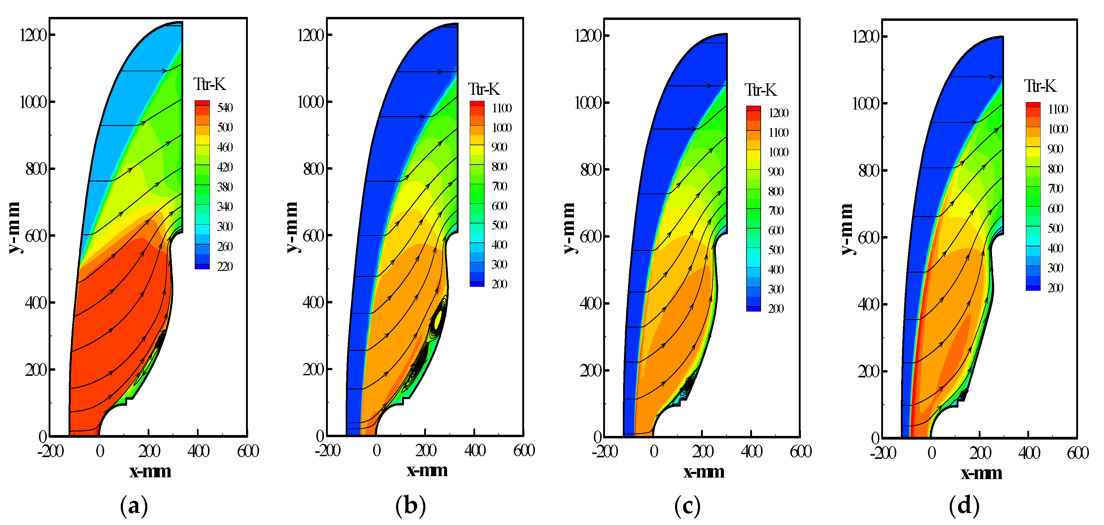
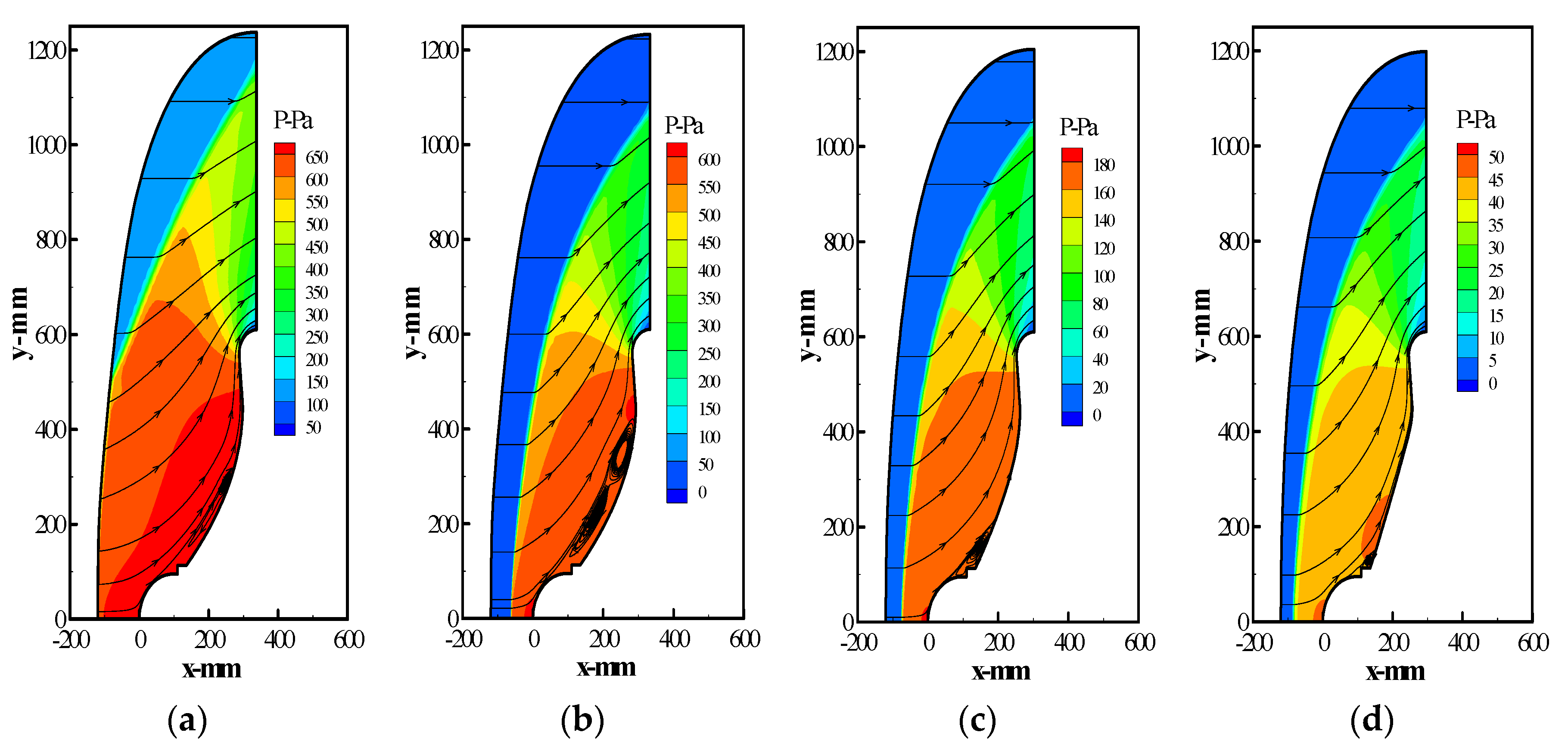
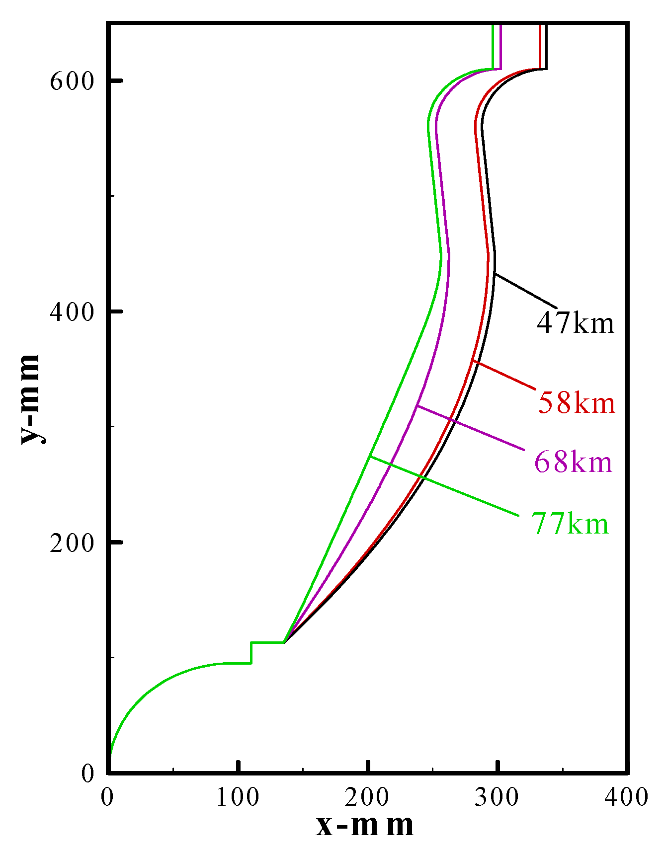
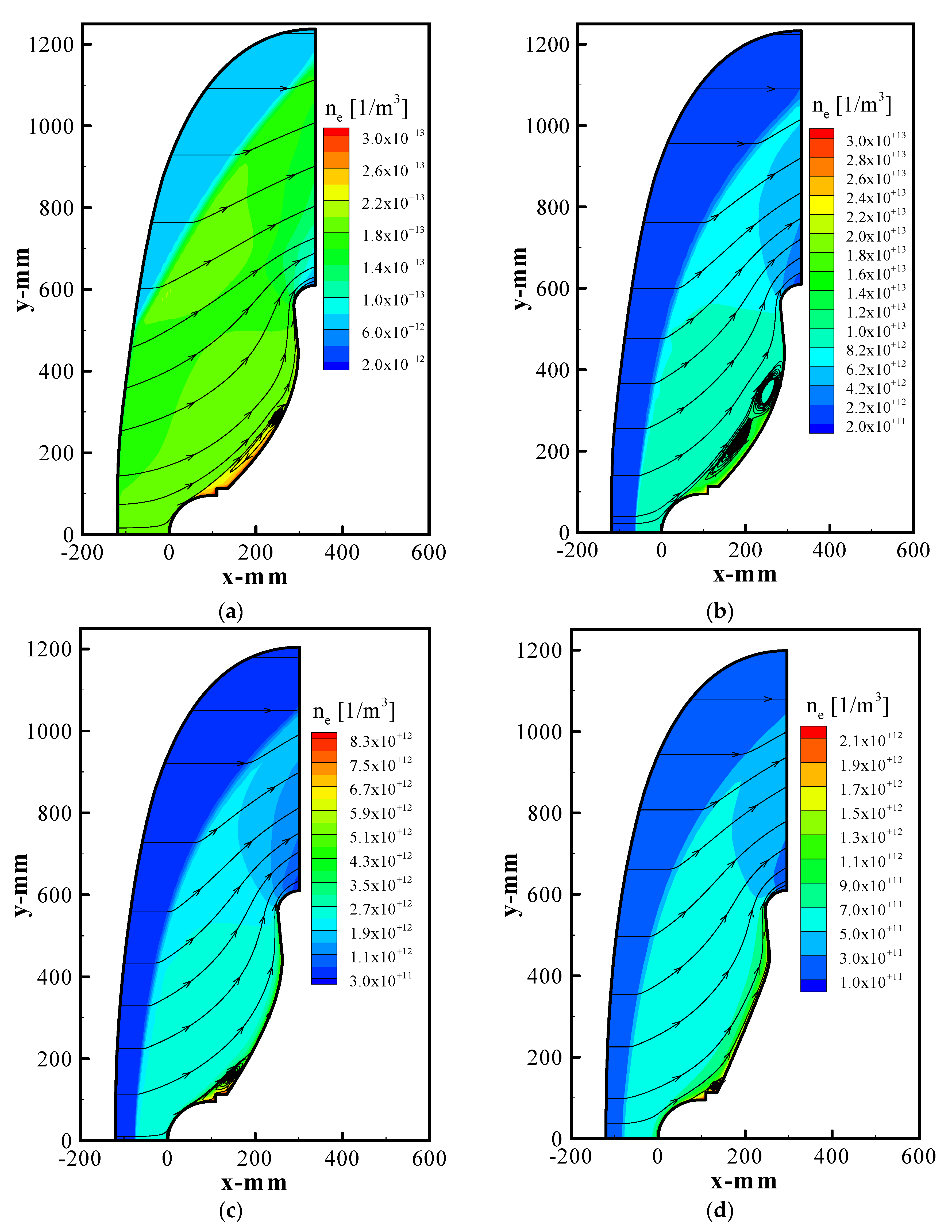
4. Results and Discussion

In this section, we will first discuss and analyze the basic flow features around the inflatable membrane vehicle at the flight altitude of 58 km. The distributions of the translational, rotational, vibrational, and electronic temperatures, pressure, deformation degree, and electron number density are analyzed in detail. Thereafter, these flow properties of the membrane vehicle at different flight altitudes from 47 km–77 km are provided and discussed, respectively.
Figure 4 shows the axial profiles of the translational, vibrational, rotational, and electron temperatures at the stagnation point of the capsule at the flight altitude of 58 km. Because the heat flux at the stagnation point of the capsule reaches the maximum at 58 km, it is necessary to analyze the temperature change along the central axis of the capsule. As shown in Figure 4, the translational temperature seems always equilibrium with the rotational temperature, but substantially differs from the electron temperature. Thus, it indicates that the plasma flow near the stagnation point of the capsule is in a thermal non-equilibrium state. However, the maxim thermal nonequilibrium degree is as small as 1.95, because of the relatively high density of air and the relatively frequent elastic collisions between heavy particles and electrons.
Figure 5 shows distributions of the translational temperature and airflow trajectories around the membrane vehicle at different flight altitudes e.g., at 47, 58, 68, and 77 km. During the reentry of the atmosphere, because viscous friction and strong compression occur between the membrane vehicle and the atmosphere, a bow shock wave with thousands of degrees Celsius usually appears in the front of the capsule’s head in a short time. Subsequently, the thermodynamic heats diffuse from the stagnation point to the torus gradually. In the layer of this shock wave, the atmospheric air dissociated and ionized severely.
In addition, with the decrease of altitude, the translational temperature increases first and then decreases around the capsule. According to the simulation results given in Figure 5c,d, the translational temperature around the membrane vehicle continues to rise under the action of aerodynamic heating and gas viscosity from the flight altitude from 77 km to 68 km. The maximum temperature reaches 1231.61 K. In the 68–58 km range, the translational temperature decreases slowly, and the maximum temperature drops to 1107 K. Within the 58–47 km range, the maximum translational temperature falls from 1107 K to 541.19 K, it proves that the membrane vehicle can effectively reduce the aerodynamic heating. When the altitude is 47 km, the shock layer at the front of the vehicle is incomplete, it is caused by the low relative ground velocity and the weak shock wave effect in the flow field.
According to the trajectory of the flow field around the vehicle, the vortex first appears at the junction of the capsule and the membrane. With the decrease of the altitude, the vortex position gradually moves to the side of the torus, and finally there is a large recirculation zone formed along the membrane. Because of the poor diffusivity, it is difficult for high temperature gases to flow into the recirculation zone, so the translational temperature of the flow field in this zone is at a low level, which satisfies the temperature requirement of the membrane material.
Figure 6 shows distributions of pressure around the membrane vehicle at different altitudes. Comparing the pressure values of the four altitudes, it can be seen that at altitude of 77–68 km, the pressure value at the front flow field of the vehicle is relatively small, which is the result of the lower atmospheric density of the flow field at high altitude. In the range of 68–47 km, the speed of the vehicle is kept above 800 m/s, and the atmospheric density increases gradually with the decrease of the altitude, which causes the pressure value at the front flow field of the vehicle to increase rapidly. From the distribution of pressure, the local pressure in the front of the capsule is higher than that of the other parts, it is because the atmospheric friction and extrusion on the front of the capsule are the most serious. Meanwhile, the flow field pressure is distributed evenly along the membrane surface during the aerodynamic heating.
Figure 7 shows the deformation degree of the membrane at different altitudes. It can be seen that with the decrease of altitude, the deformation degree of the membrane increases with the increase of the dynamic pressure acting on the membrane. Specifically, when the pressure on the membrane surface increases, the flare angle of the vehicle decreases significantly and the inflation torus moves backward, resulting in the membrane being stretched and the degree of deformation increasing.
Figure 8 shows distributions of the electron density around the membrane vehicle at different flight altitudes. According to the simulation results given in Figure 8a–d, the flight altitude is reduced from 77 km to 47 km, and the electron number density of the flow field at the front of the vehicle increases with the decrease in altitude, but its maximum value is much less than the critical electron number density 3.167 × 10¹⁶ (1/m3) for the blackout. This may result from the characteristics of the low ballistic coefficient of the vehicle, which can effectively reduce the ionization and dissociation reaction rates of gas molecules and vehicle materials in the shock layer, and finally reduce the electron number density. In addition, it can be seen from the electron density distribution that the region with higher electron number density is the junction of the capsule and the membrane, and there is even distribution along the radial direction of the membrane. Finally, it forms an electron layer with a small thickness on the surface of the vehicle.
In this paper, the variation characteristics of the flow field parameters around the inflatable membrane vehicle with height are given computationally through multiphysics field coupling equations. Nevertheless, there are still some aspects that can be improved and continued to be studied. Since the uncertain of the elasticity, i.e., Young’s modulus, is one of the important factors affecting the prediction of the reentry environment of inflatable membrane vehicles, additional parametric studies on Young’s modulus could be conducted in the future to analyze and discuss the effect of various elasticities on the aerodynamic heating of inflatable reentry vehicles, which would be an interesting research topic for the selection of membrane materials.

5. Conclusions

In this paper, the flow field characteristics around the membrane vehicle, including the translational temperature, vortex, pressure, and electron number density were investigated by solving the coupled multiphysics field equations. The results of the study are as follows:
(1) The thermodynamic heat in the flow field gradually spread from the vehicle’s stagnation point to the inflatable torus as the reentry altitude decreased, and its translational temperature showed a trend in first increasing and then decreasing numerically, with a maximum temperature of 1231.61 K. This proved that the aerodynamic heating during the reentry process was alleviated.
(2) The vortex in the flow field first appeared at the junction of the capsule and the membrane, gradually moving to the side of the torus, and finally forming a recirculation region along the whole membrane. The poor diffusion of the high-temperature gas made it difficult to flow into this region and ensured a low surface heat flux of the membrane.
(3) The flow field pressure was uniformly distributed along the surface of the membrane, and the value tended to increase gradually. The degree of deformation of the membrane was proportional to the pressure, which acted on the membrane.
(4) The electron number density was uniformly distributed along the radial direction of the membrane, and its value increased with decreasing altitude, but the maximum value was much less than the critical electron number density of 3.167 × 10¹⁶ (1/m3) for the blackout to occur.
In summary, this paper has presented a numerical simulation and study of the flow field characteristics of a membrane vehicle, which not only proves that this type of vehicle can effectively mitigate the aerodynamic heating and communication interruptions during reentry, but also provides a feasible mathematical model for future research on flexible vehicles by introducing the membrane deformation equation.

Author Contributions

Conceptualization, Y.T.; data curation, Z.Q.; formal analysis, B.L.; funding acquisition, M.Y.; investigation, Z.Q.; methodology, Y.T.; resources, B.L.; writing—original draft preparation, M.Y. All authors have read and agreed to the published version of the manuscript.

Funding

This research was funded by the National Natural Science Foundation of China (Grant No. 12175177) and the China Postdoctoral Science Foundation (Grant No. 2021M693889).

Institutional Review Board Statement

Not applicable.

Informed Consent Statement

Not applicable.

Data Availability Statement

The data presented in this study are available on request from the corresponding author. The data are not publicly available due to privacy.

Acknowledgments

All the calculations involved in this study were carried out on Tianhe-2 Supercomputer at the National Supercomputer Center in Guangzhou, China.

Conflicts of Interest

The authors declare no conflict of interest.

References

  1. Wang, R.X.; Wang, Z.W.; Zheng, H.W.; Song, H.W. Comparison of Strategies for Coupled Flow-Thermal Analysis of Thermal Protection System at Hypersonic Flight Condition. Int. J. Aeronaut. Space Sci. 2019, 21, 347–362. [Google Scholar] [CrossRef]
  2. Takahashi, Y.; Koike, T.; Oshima, N.; Yamada, K. Aerothermodynamic analysis for deformed membrane of inflatable aeroshell in orbital reentry mission. Aerosp. Sci. Technol. 2019, 92, 858–868. [Google Scholar] [CrossRef]
  3. Kim, Y.; Lee, J.H.; Kim, K. A Numerical Study on the Effect of the Umbilical Plate on Longitudinal Controllability of a Low Aspect Ratio Launch Vehicle. Int. J. Aeronaut. Space Sci. 2019, 20, 870–878. [Google Scholar] [CrossRef]
  4. Yang, M.F.; Zhang, W.; Peng, J.; Zhang, G. Technical advancements and significance of circumlunar return and reentry spacecraft. Sci. China Technol. Sci. 2015, 58, 738–745. [Google Scholar] [CrossRef]
  5. Wei, J.Z.; Tan, H.F.; Wang, W.Z.; He, X.D. New Trends in Inflatable Re-Entry Aeroshell. J. B. Univ. Aeronaut. Astronaut. 2013, 34, 881–890. [Google Scholar]
  6. Hong, Y.; Xue, G. The feasibility analysis of the application of TPV system in reentry. Sci. China Technol. Sci. 2010, 53, 3310–3315. [Google Scholar]
  7. Reynier, P.; Evans, D. Postflight Analysis of Inflatable Reentry and Descent Technology Blackout During Earth Reentry. J. Spacecr. Rockets 2009, 46, 800–809. [Google Scholar] [CrossRef]
  8. Clark, I.G.; Hutchings, A.L.; Tanner, C.L.; Braun, R.D. Supersonic Inflatable Aerodynamic Decelerators for Use On Future Robotic Missions to Mars. J. Spacecr. Rockets 2009, 46, 340–352. [Google Scholar] [CrossRef] [Green Version]
  9. Rohrschneider, R.R.; Braun, R.D. Survey of Ballute Technology for Aerocapture. J. Spacecr. Rocket. 2007, 44, 10–23. [Google Scholar] [CrossRef] [Green Version]
  10. Yamada, K.; Abe, T.; Suzuki, K.; Honma, N.; Koyama, M.; Nagata, Y.; Abe, D.; Kimura, Y.; Hayashi, A.K.; Akita, D.; et al. Deployment and Flight Test of Inflatable Membrane Aeroshell Using Large Scientific Balloon. In Proceedings of the 21st AIAA Aerodynamic Decelerator Systems Technology Conference and Seminar, Dublin, Ireland, 23–26 May 2011. [Google Scholar]
  11. Yamada, K.; Akita, D.; Sato, E.; Suzuki, K.; Narumi, T.; Abe, T. Flare-Type Membrane Aeroshell Flight Test at Free Drop from a Balloon. J. Spacecr. Rockets 2009, 46, 606–614. [Google Scholar] [CrossRef]
  12. Kusano, Y.; Nakashino, K. Experimental and Numerical Study of Structural Strength of Flare-Type Membrane Aeroshell with Inflatable Ring. Trans. JSASS Aerosp. Tech. Jpn. 2014, 12, 99–105. [Google Scholar] [CrossRef]
  13. Yamada, K.; Koyama, M.; Kimura, Y.; Suzuki, K.; Abe, T.; Hayashi, A.K. Hypersonic Wind Tunnel Test of a Flare-type Membrane Aeroshell for Atmospheric Entry Capsules. Trans. JSASS Aerosp. Tech. Jpn. 2010, 8, 27–32. [Google Scholar] [CrossRef]
  14. Yamada, K.; Abe, T.; Suzuki, K.; Imamura, O.; Akita, D. Reentry Demonstration Plan of Flare-type Membrane Aeroshell for Atmospheric Entry Vehicle Using a Sounding Rocket. In Proceedings of the 21st AIAA Aerodynamic Decelerator Systems Technology Conference and Seminar, Dublin, Ireland, 23–26 May 2011. [Google Scholar]
  15. Yamada, K.; Nagata, Y.; Abe, T.; Suzuki, K.; Imamura, O.; Akita, D. Suborbital Reentry Demonstration of Inflatable Flare-Type Thin-Membrane Aeroshell Using a Sounding Rocket. J. Spacecr. Rockets 2015, 52, 275–284. [Google Scholar] [CrossRef]
  16. Yamada, K.; Nagata, Y.; Abe, T.; Suzuki, K.; Imamura, O.; Akita, D. Reentry Demonstration of Flare-type Membrane Aeroshell for Atmospheric Entry Vehicle using a Sounding Rocket. In Proceedings of the AIAA Aerodynamic Decelerator Systems (ADS) Conference, Daytona Beach, FL, USA, 25–28 March 2013. [Google Scholar]
  17. Nagata, Y.; Yamada, K.; Abe, T.; Suzuki, K. Attitude Dynamics for Flare-type Membrane Aeroshell Capsule in Re-entry Flight Experiment. In Proceedings of the AIAA Aerodynamic Decelerator Systems (ADS) Conference, Daytona Beach, FL, USA, 25–28 March 2013. [Google Scholar]
  18. Takahashi, Y.; Ha, D.; Oshima, N.; Yamada, K.; Abe, T.; Suzuki, K. Aerodecelerator Performance of Flare-Type Membrane Inflatable Vehicle in Suborbital Reentry. J. Spacecr. Rockets 2017, 54, 993–1004. [Google Scholar] [CrossRef] [Green Version]
  19. Takahashi, Y.; Yamada, K.; Abe, T.; Suzuki, K. Aerodynamic Heating Around Flare-Type Membrane Inflatable Vehicle in Suborbital Reentry Demonstration Flight. J. Spacecr. Rockets 2015, 52, 1530–1541. [Google Scholar] [CrossRef] [Green Version]
  20. Takahashi, Y.; Yamada, K.; Abe, T. Examination of Radio Frequency Blackout for an Inflatable Vehicle During Atmospheric Reentry. J. Spacecr. Rockets 2014, 51, 430–441. [Google Scholar] [CrossRef] [Green Version]
  21. Takahashi, Y.; Yamada, K.; Abe, T. Radio Frequency Blackout Possibility for an Inflatable Reentry Vehicle. In Proceedings of the 42nd AIAA Fluid Dynamics Conference and Exhibit, New Orleans, LA, USA, 25–28 June 2012. [Google Scholar]
  22. Gilbert, C.; Mazoue, F.; Ortega, G.; Pichkhadze, K.; Costa, R.D. New Space Application Opportunities Based on the Inflatable Reentry & Descent Technology IRDT. In Proceedings of the Aiaa International Air & Space Symposium & Exposition: The Next 100 Years, Dayton, OH, USA, 14–17 July 2013. [Google Scholar]
  23. Marraffa, L.; Vennemann, D.; Anschuetz, U.; Walther, S.; Stelter, C.S.; Pitchkhadze, K.M.; Finchenko, V.S. IRDT—Inflatable Re-entry and Descent Technology. Hot Struct. Therm. Prot. Syst. Space Veh. 2003, 521, 19–28. [Google Scholar]
  24. Litton, D.K.; Bose, D.M.; Cheatwood, F.M.; Hughes, S.; Wright, H.S.; Lindell, M.C.; Derry, S.D.; Olds, A. Inflatable Reentry Vehicle Experiment (IRVE)—4 Overview. In Proceedings of the 21st AIAA Aerodynamic Decelerator Systems Technology Conference and Seminar, Dublin, Ireland, 23–26 May 2011. [Google Scholar]
  25. Carlson, L.A.; Horn, W.J. New thermal and trajectory model for high-altitude balloons. J. Aircr. 1983, 20, 500–507. [Google Scholar] [CrossRef]
  26. Yos, J. Transport properties of nitrogen, hydrogen, oxygen, and air to 30,000 K. In Proceedings of the Research and Advanced Developm Ent Division Avco Corporation, Wilmington, NC, USA, 22 March 1963. [Google Scholar]
  27. Gupta, R.N.; Yos, J.M.; Thompson, R.A. A review of reaction rates and thermodynamic and transport properties for the 11-species air model for chemical and thermal nonequilibrium calculations to 30,000 K. NTRS 1990, 1, 1–68. [Google Scholar]
  28. Shima, E.; Kitamura, K. Parameter-Free Simple Low-Dissipation AUSM-Family Scheme for All Speeds. AIAA J. 2011, 49, 1693–1709. [Google Scholar] [CrossRef]
  29. Jameson, A.; Yoon, S. Lower-upper implicit schemes with multiple grids for the Euler equations. AIAA J. 1987, 25, 929–935. [Google Scholar] [CrossRef]
  30. Yamada, K.; Suzuki, K. A Particle-Based Model and Its Validation for Deformation Analysis of Membrane Aeroshell. J. Jpn Soc. Aeronaut. Space Sci. 2005, 53, 51–60. [Google Scholar]
Figure 1. Physical model of the membrane vehicle and its main dimensions: (a) compositions of the membrane vehicle and (b) the main dimensions of the membrane vehicle.
Mathematics 10 00832 g001
Figure 2. Calculation conditions of heat conduction model for the capsule: (a) computational grid and (b) boundary conditions and computational domain.
Mathematics 10 00832 g002
Figure 3. Computational grid system of the membrane vehicle at 58 km altitude.
Mathematics 10 00832 g003
Figure 4. Axial distributions of the translational, vibrational, rotational, and electron temperatures at the stagnation point of the capsule at the flight altitude of 58 km.
Mathematics 10 00832 g004
Figure 5. Distributions of translational temperature and airflow trajectory around the vehicle at different altitudes: (a) 47 km, (b) 58 km, (c) 68 km, and (d) 77 km.
Mathematics 10 00832 g005
Figure 6. Distributions of pressure around the membrane vehicle at different altitudes: (a) 47 km, (b) 58 km, (c) 68 km, and (d) 77 km.
Mathematics 10 00832 g006
Figure 7. Relationship between the deformation degree of the membrane and the altitudes.
Mathematics 10 00832 g007
Figure 8. Distributions of the electron density around the vehicle at different altitudes: (a) 47 km, (b) 58 km, (c) 68 km, and (d) 77 km.
Mathematics 10 00832 g008
Table 1. Flight sequence of the experiment.
Time, sAltitude, kmCase
00The rocket launched as planned
6070The front cone of the rocket opened automatically
90100The aeroshell cover was deployed under external conditions
95106CO2 was injected into the torus
100111The aircraft disengaged from the rocket
191150The vehicle reached the highest point of the orbit
32070The acceleration of the vehicle decreases gradually
40032Velocity became less than 150 m/s and attained equilibrium
13200Splashdown
Table 2. Material properties of the vehicle.
Polyimide ResinAluminum
Density, kg/m314002700
Specific heat, J/(kg·K)1050900
Heat conductivity, W/(m·K)0.290237
Emissivity0.90.3
Table 3. Calculation conditions.
Elapsed Time, s316324332344
Altitude, km77.068.058.047.0
Velocity, m/s1284.51324.51249.5749.7
Density, kg/m33.03 × 10−51.12 × 10−44.24 × 10−41.67 × 10⁻³
Temperature, K203.7221.5248.3263.0
Publisher’s Note: MDPI stays neutral with regard to jurisdictional claims in published maps and institutional affiliations.

