Heavy Ion Induced Single Event Effects Characterization on an RF-Agile Transceiver for Flexible Multi-Band Radio Systems in NewSpace Avionics

 , ,
, ,
Abstract
1. Introduction
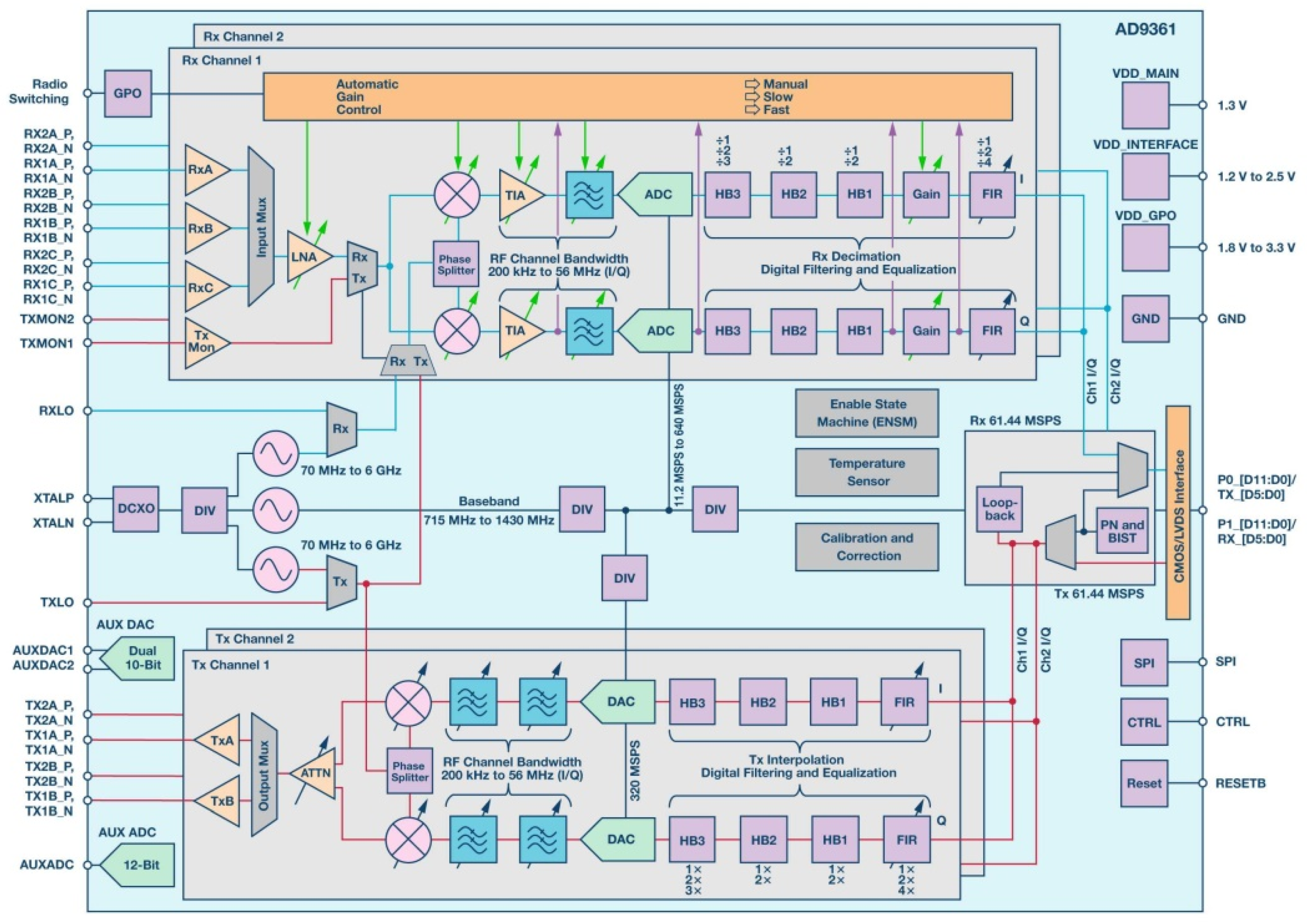
2. The Highly Integrated Radio Frequency (RF)-Agile Transceiver
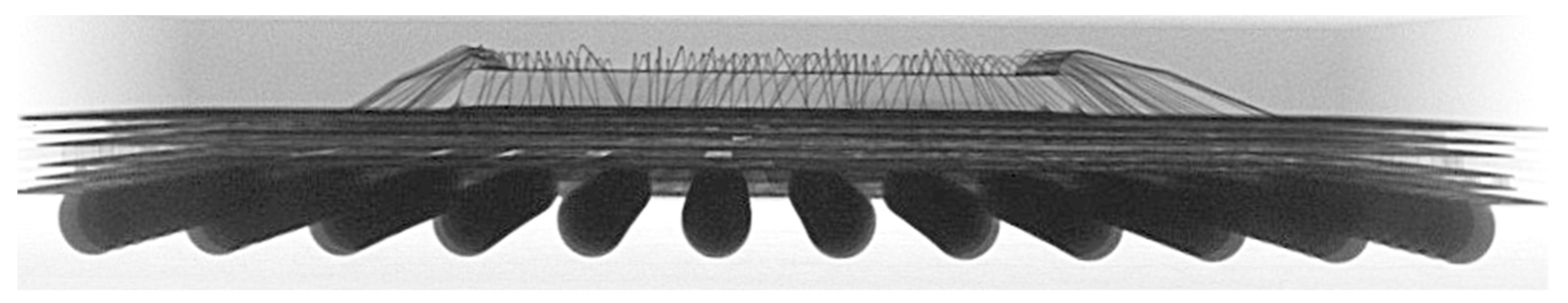
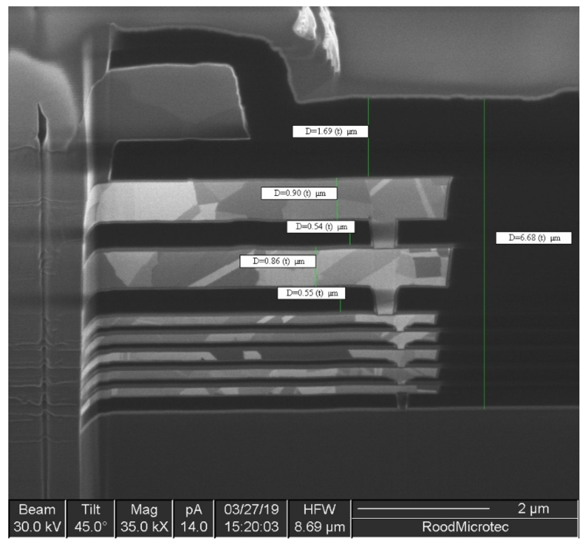
2.1. Device Packaging and Chip Technology
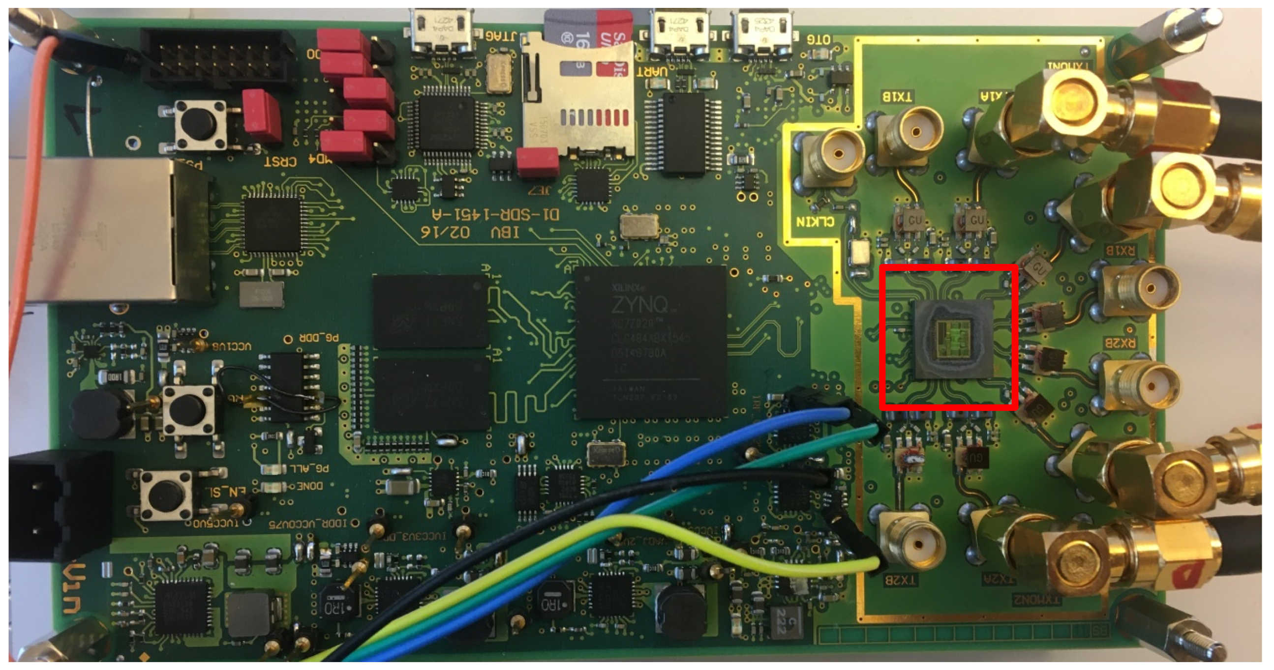
2.2. Test Setup Preparation and Sample Information
3. Test Conditions and Requirements
3.1. Test Site
3.2. Test Requirements
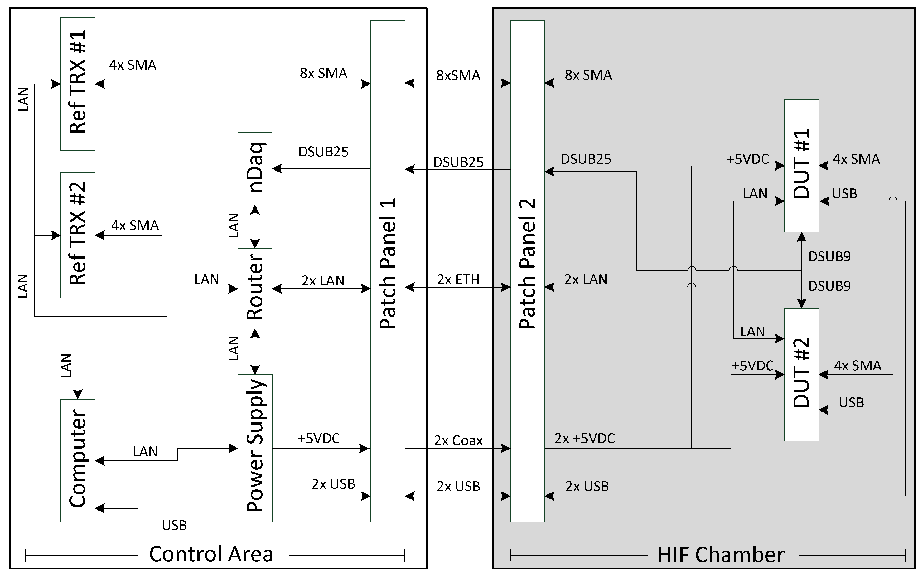
4. Test Setup and Procedures
4.1. Test Setup
4.2. Failure Classification
4.2.1. Upsets in the Device Functional Registers
4.2.2. Single Event Functional Interrupts
4.2.3. Corrupted Transmitted and Received RF Data
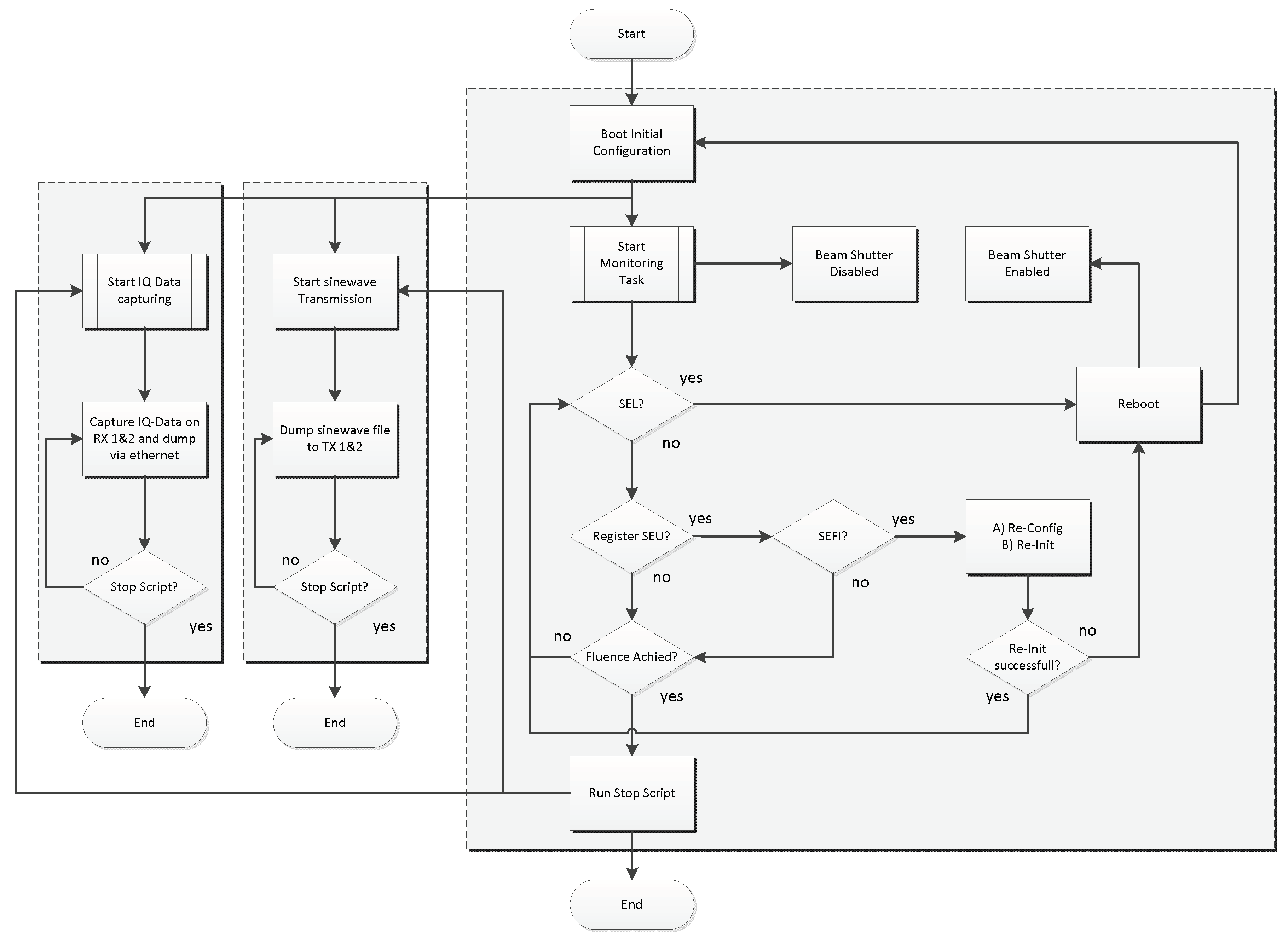
4.3. Test Procedures
5. Experimental Results
5.1. Destructive Events
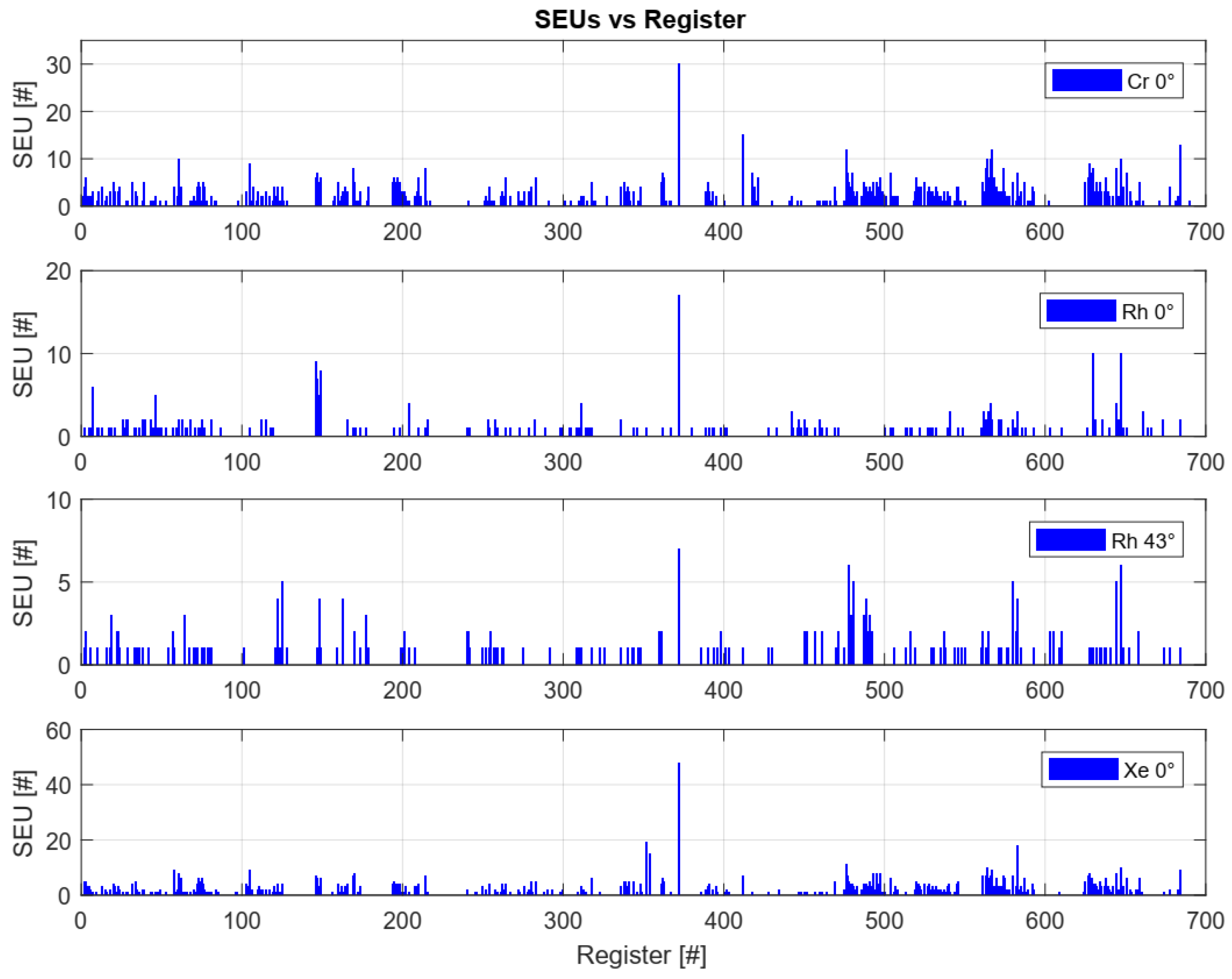
5.2. Functional Register Upsets
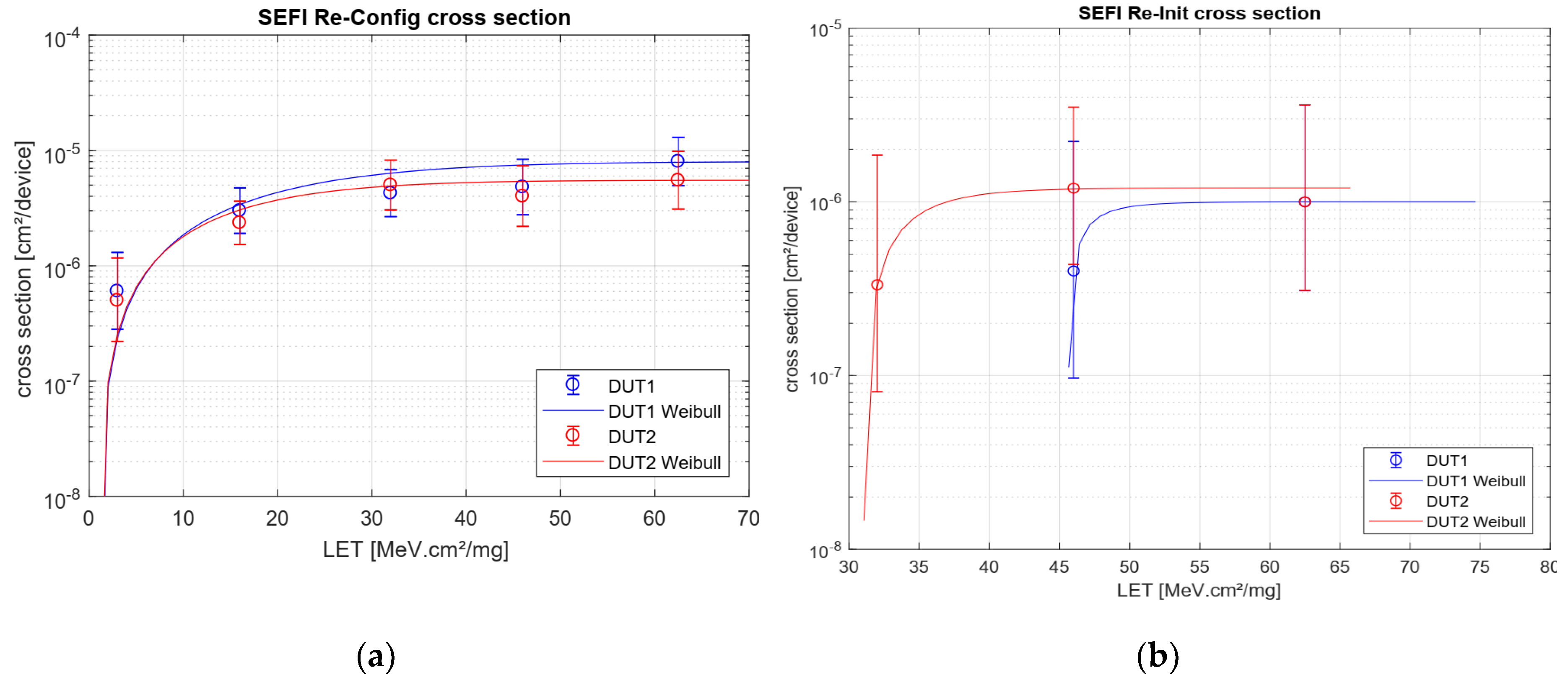
5.3. Single Event Functional Interrupts
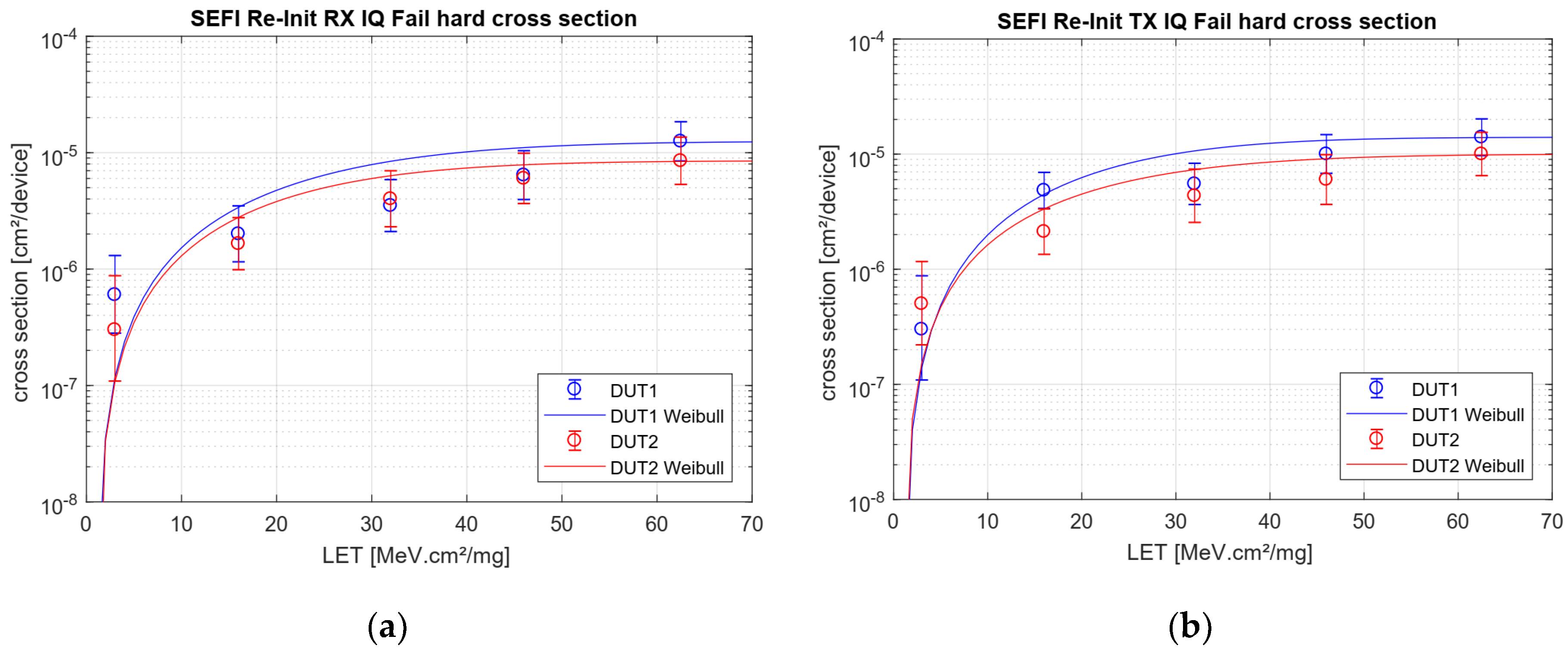
5.4. Corrupted Transmitted and Received RF Data
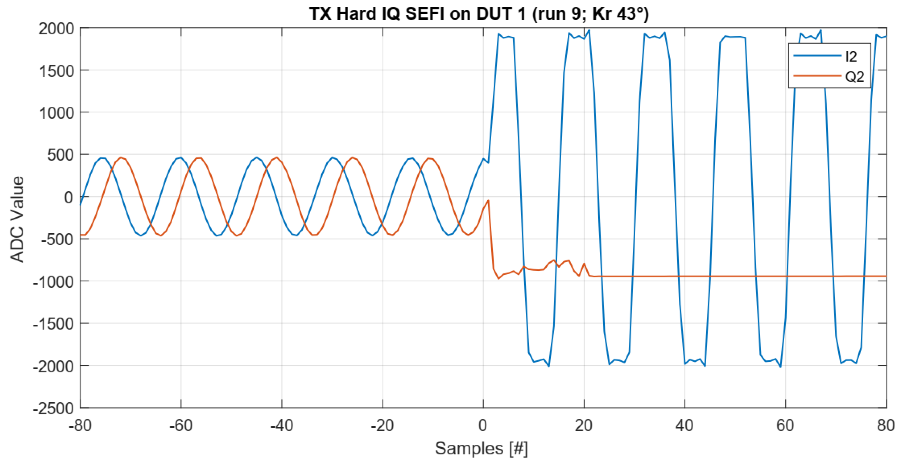
5.4.1. Hard IQ SEFI
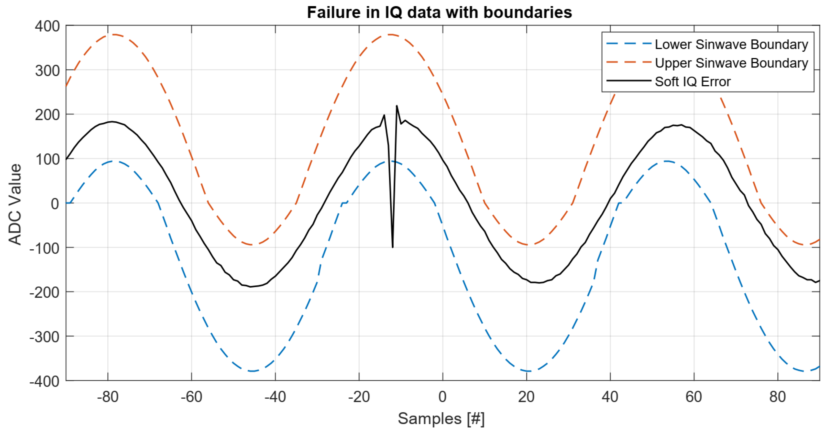
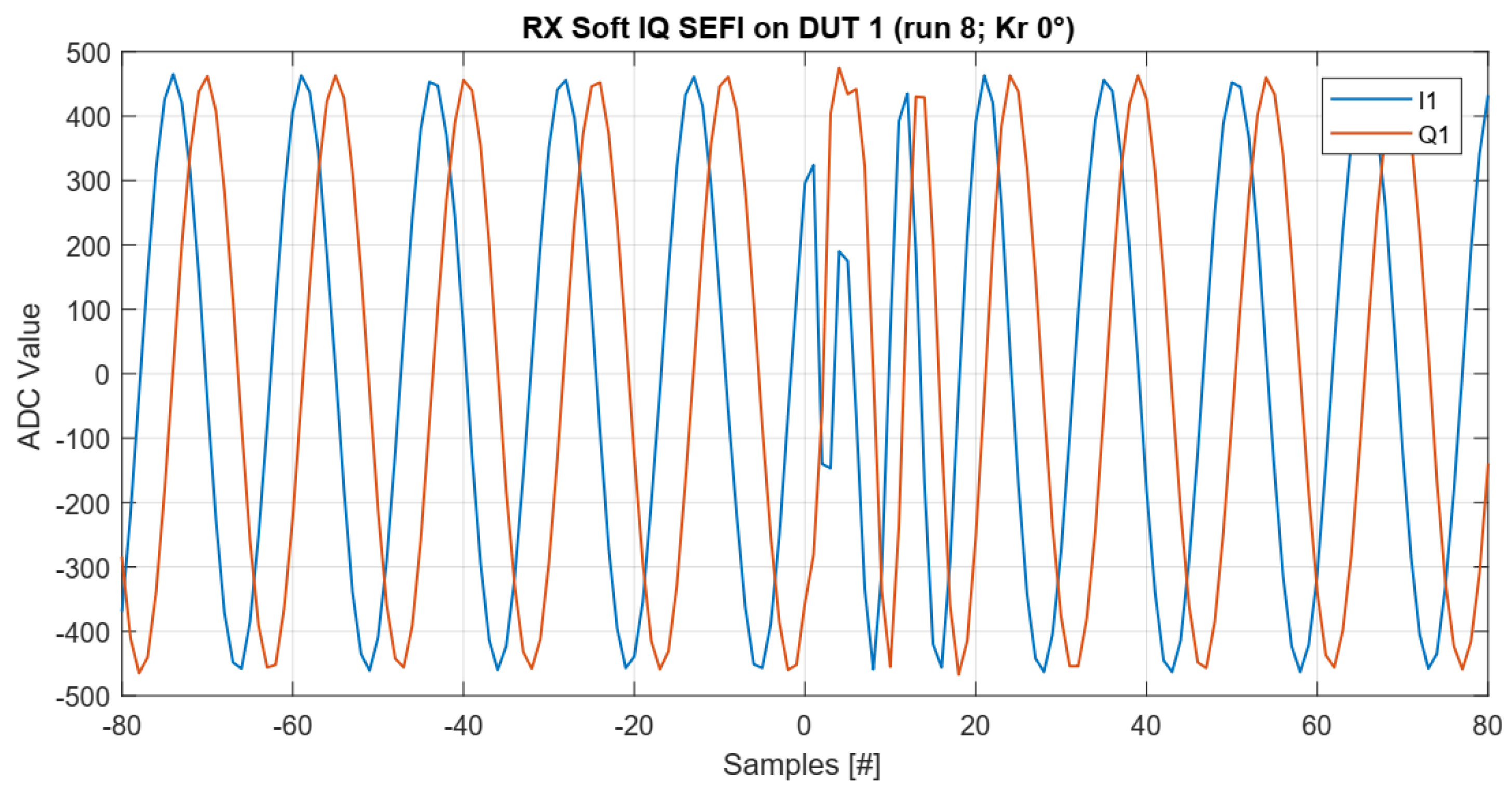
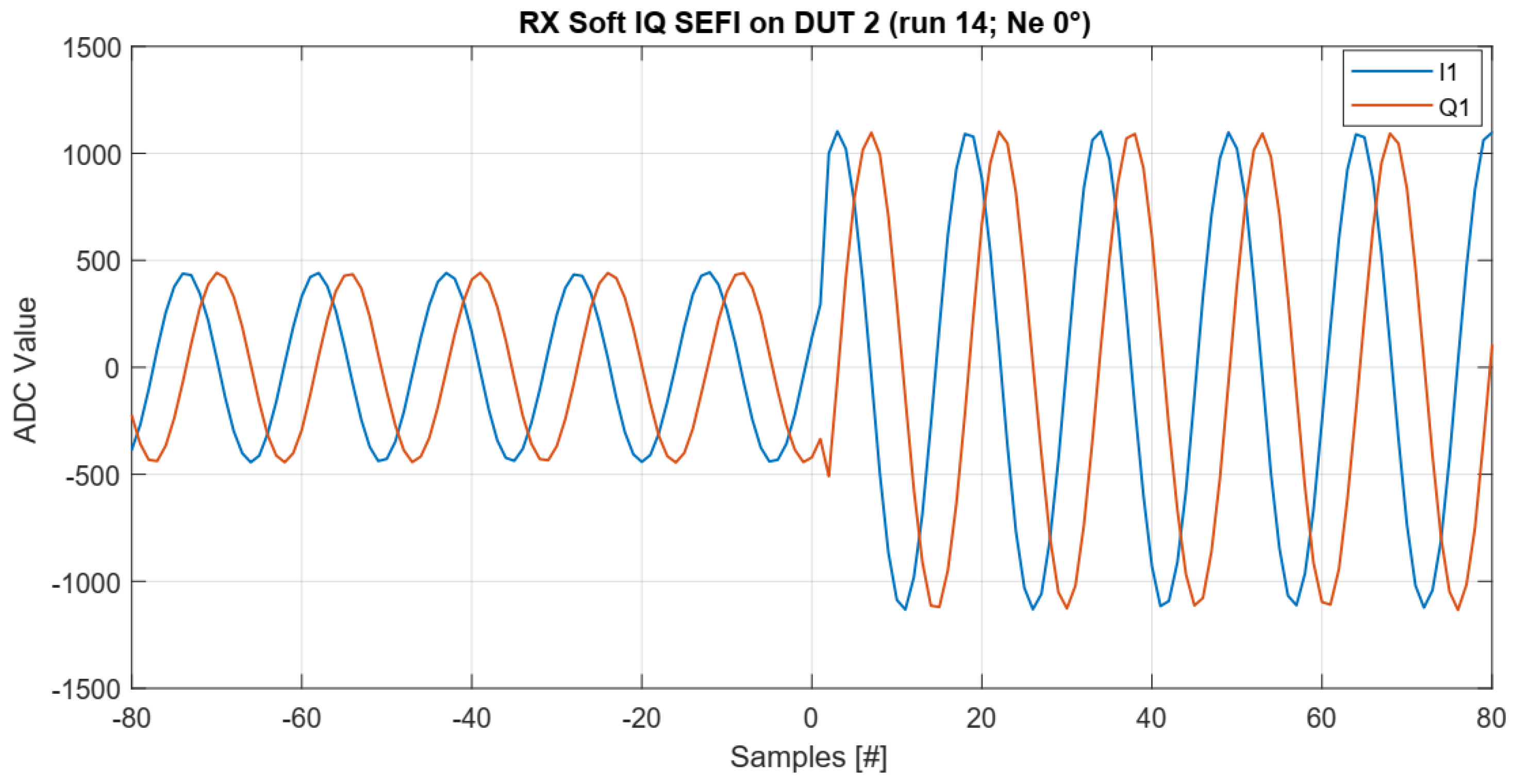
5.4.2. Soft IQ SEFI
6. Analysis and Discussion
6.1. High Current States
6.2. SEFIs in the IQ Data
6.2.1. Soft IQ SEFIs
6.2.2. Hard IQ SEFIs
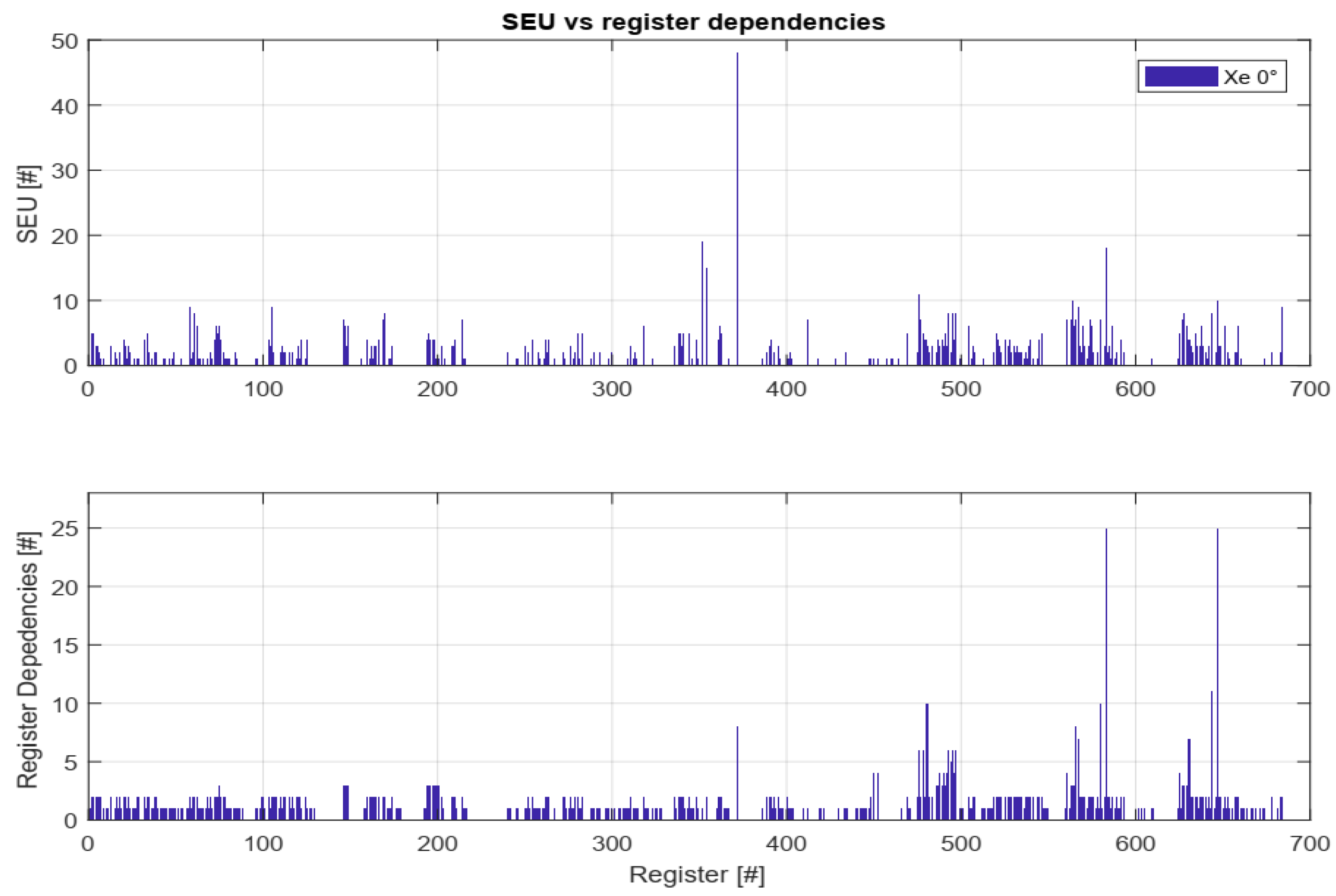
6.3. SEU and Functional Register Dependencies
6.4. Correlation of SEUs to IQ SEFIs
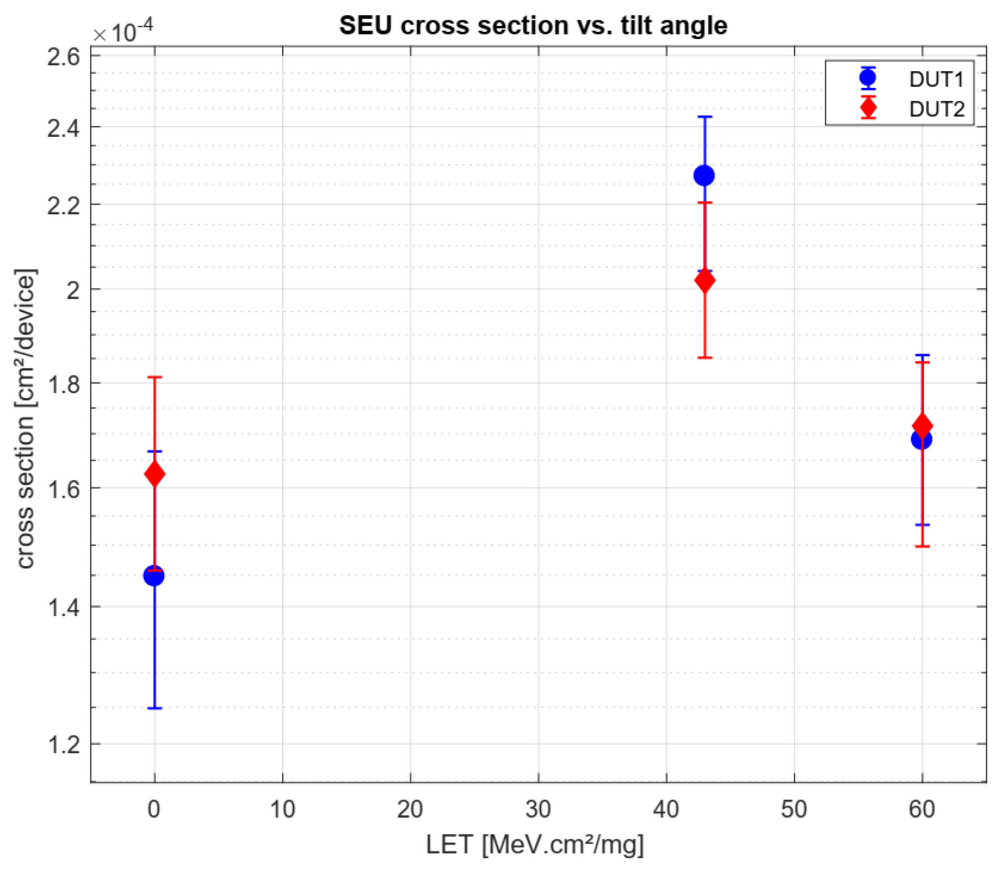
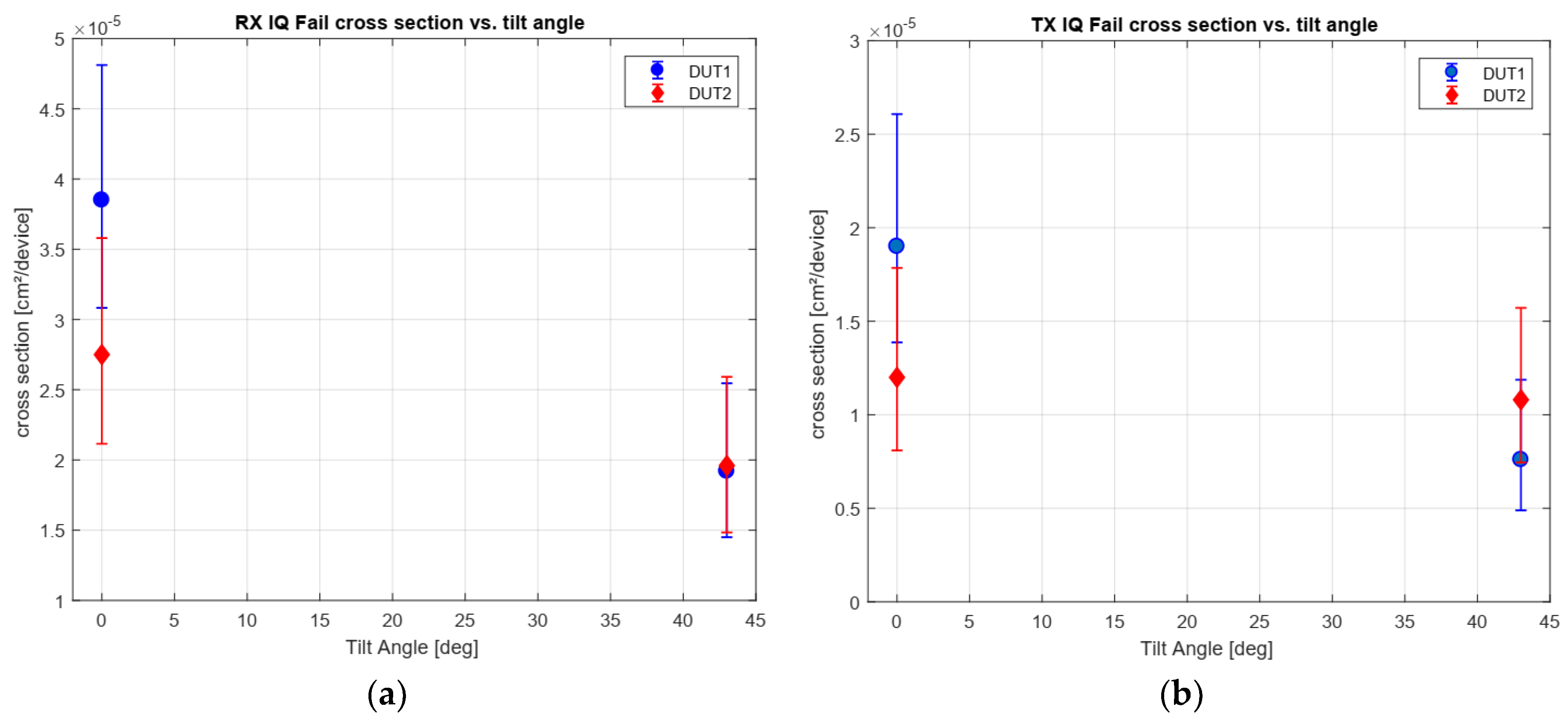
6.5. Tilt Angle Dependicies
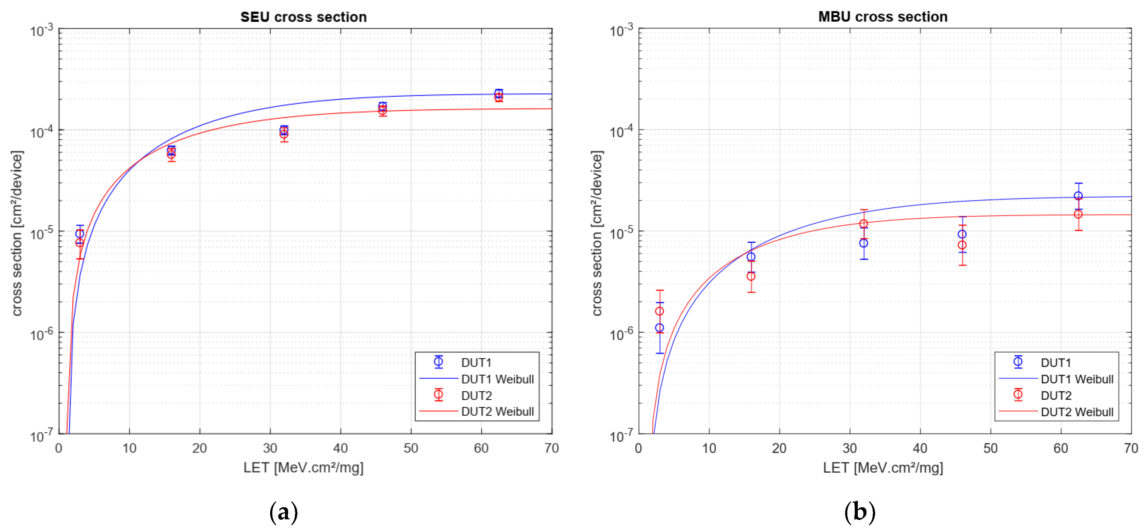
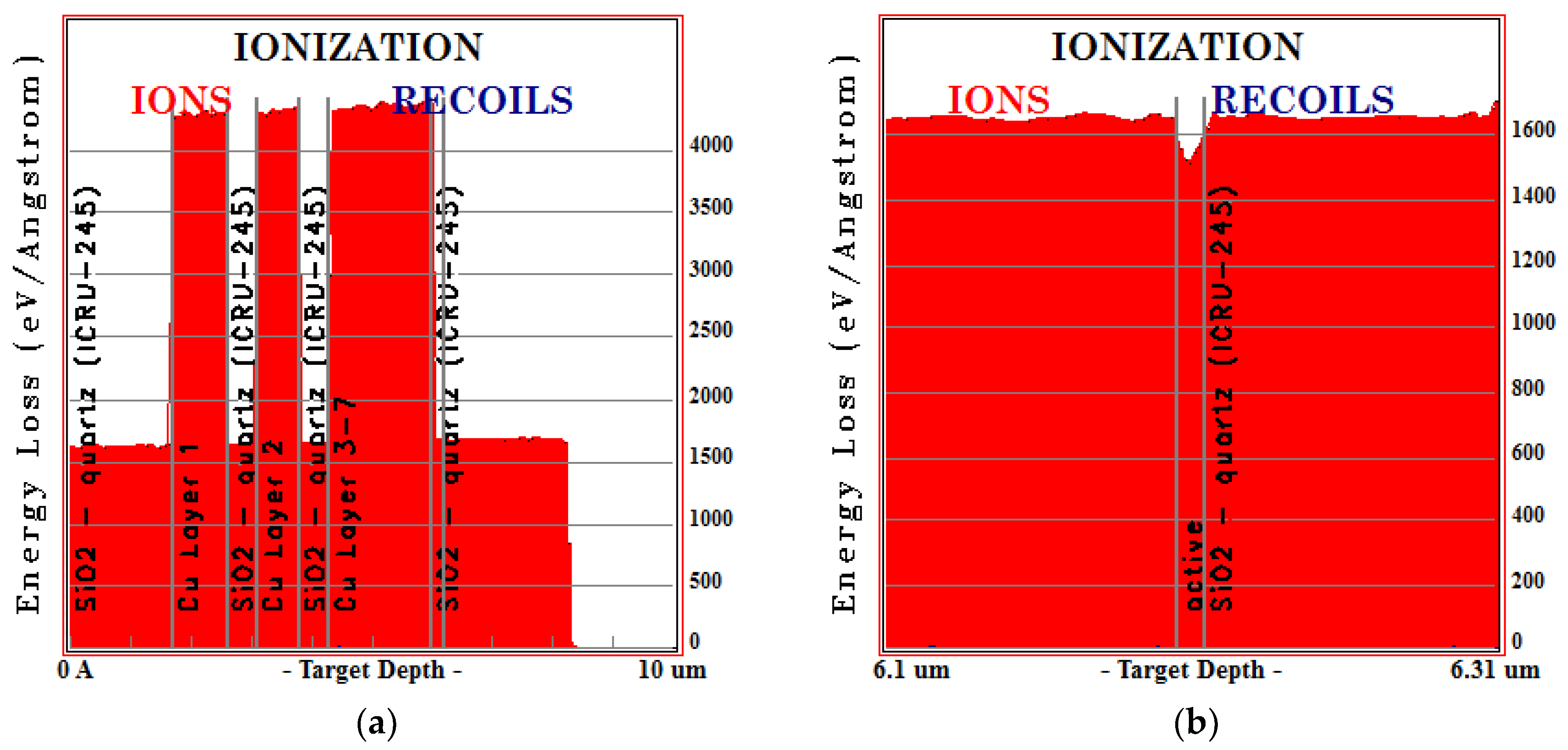
6.6. LET on Active Region
6.7. Error Rate Prediction for Reference Missions
7. Conclusions
Author Contributions
Funding
Conflicts of Interest
References
- Budroweit, J. Design of a Highly Integrated and Reliable SDR Platform for Multiple RF Applications on Spacecraft. In Proceedings of the GLOBECOM 2017—2017 IEEE Global Communications Conference, Singapore, 4–8 December 2017; pp. 1–6. [Google Scholar]
- Budroweit, J.; Koelpin, A. Design challenges of a highly integrated SDR platform for multiband spacecraft applications in radiation environments. In Proceedings of the 2019 IEEE Topical Workshop on Internet of Space (TWIOS), Anaheim, CA, USA, 14–17 January 2018; pp. 9–12. [Google Scholar]
- Budroweit, J.; Jaksch, M.M. In-Situ TID Testing and Characterization of a Highly Integrated RF Agile Transceiver for Multi-Band Radio Applications in a Radiation Environment. In Proceedings of the 2019 IEEE International Conference on Wireless for Space and Extreme Environments (WiSEE), Ottawa, ON, Canada, 16–18 October 2019; pp. 1–6. [Google Scholar]
- Budroweit, J.; Jaksch, M.P.; Sznajder, M. Proton Induced Single Event Effect Characterization on a Highly Integrated RF-Transceiver. Electronics 2019, 8, 519. [Google Scholar] [CrossRef]
- Pu, D.; Cozma, A.; Hill, T. Four Quick Steps to Production: Using Model-Based Design for Software-Defined Radio. Analog. Dialogue 2015, 49, 1–5. [Google Scholar]
- AD9361 Data Sheet. Available online: https://www.analog.com/media/en/technical-documentation/data-sheets/AD9361.pdf (accessed on 6 December 2019).
- AD9361 Material Declaration. Available online: https://www.analog.com/media/en/package-pcbresources/material-declaration/cspbga/cspbga_10x10(bc-144-7).pdf (accessed on 6 December 2019).
- Single Event Effects Test Method and Guidelines, ESCC Basic Specification No. 25100; ESA: Paris, France, 2014; Issue 2.
- Gruermann, K.; Walter, D.; Herrmann, M.; Gliem, F.; Kettunen, H.; Ferlet Cavrois, V. SEU and MBU angular dependence of Samsung and Micron 8-Gbit SLC NAND-Flash memories under heavy-ion irradiation. In Proceedings of the IEEE Radiation Effects Data Workshop, Las Vegas, NV, USA, 25–29 July 2011; pp. 1–5. [Google Scholar]
- Cellere, G.; Paccagnella, A.; Visconti, A.; Bonanomi, M.; Harboe-Sorensen, R.; Virtanen, A. Angular dependence of heavy-ion effects in floating gate memory arrays. IEEE Trans. Nucl. Sci. 2007, 54, 2371–2378. [Google Scholar] [CrossRef]
- Zhang, H.; Jiang, H.; Assis, T.R.; Ball, D.R.; Narasimham, B.; Anvar, A.; Massengill, L.W.; Bhuva, B.L. Angular Effects of Heavy-Ion Strikes on Single-Event Upset Response of Flip-Flop Designs in 16-nm Bulk FinFET Technology. IEEE Trans. Nucl. Sci. 2017, 64, 491–496. [Google Scholar] [CrossRef]
- Chen, D.; Mondy, T.; Phan, A. Heavy Ion Test Report for the AD9364 RF Transceiver. Available online: https://ntrs.nasa.gov/archive/nasa/casi.ntrs.nasa.gov/20170009007.pdf (accessed on 2 December 2019).
- SRIM-2013 Professional Software. Available online: http://www.srim.org/ (accessed on 18 December 2019).
- The OMERE Software. Available online: http://www.trad.fr/en/space/omere-software/ (accessed on 20 December 2019).


| Sample Number | Test Board ID | Full Part Number | Lot Date Code (LDC) | Part Serial Number | Fabrication Site |
|---|---|---|---|---|---|
| 1 | 01 | AD9364BBCZ | #1350 | 2769606.1 | Singapore |
| 2 | 02 | AD9364BBCZ | #1350 | 2769606.1 | Singapore |
| Ion Type | Ion Element | Energy on Device | Range on Device (Si) | LET on Device | Adjustable Flux |
|---|---|---|---|---|---|
| (MeV) | (um) | (MeV.cm²/mg) | (#/cm²/s) | ||
| Neon | 22Ne7+ | 238 | 202 | 3.3 | <1 × 101 to 1.5 × 10⁴ |
| Chrom | 53Cr16+ | 505 | 105.5 | 16.1 | <1 × 101 to 1.5 × 10⁴ |
| Krypton | 84Kr25+ | 769 | 94.2 | 32.4 | <1 × 101 to 1.5 × 10⁴ |
| Rhodium | 103Rh31+ | 957 | 87.3 | 46.1 | <1 × 101 to 1.5 × 10⁴ |
| Xenon | 124Xe35+ | 995 | 73.1 | 62.5 | <1 × 101 to 1.5 × 10⁴ |
| Ion | LET (MeV.cm²/mg) | SEUs (#) | IQ Hard SEFIs (TX + RX) (#) | SEFI/SEU Ratio (%) |
|---|---|---|---|---|
| Ne | 3.30 | 93 | 6 + 8 | 15.1 |
| Cr | 16.00 | 375 | 6 + 15 | 5.6 |
| Kr | 32.00 | 395 | 9 + 14 | 5.9 |
| Rh | 46.00 | 422 | 6 + 8 | 3.3 |
| Xe | 62.50 | 454 | 10 + 14 | 5.3 |
| Orbit | SEE Type | Heavy Ion SEE Rate (failure/device/day) | Years for Failure |
|---|---|---|---|
| LEO | SEU | 3.98 × 10⁻⁴ | 6.88 |
| GEO | SEU | 1.17 × 10⁻³ | 2.34 |
| LEO | SEFI re-config. | 2.22 × 10⁻⁵ | 123 |
| GEO | SEFI re-config. | 6.43 × 10⁻⁵ | 43 |
| LEO | Hard RX IQ SEFI | 1.26 × 10⁻⁵ | 217 |
| GEO | Hard RX IQ SEFI | 3.77 × 10⁻⁵ | 73 |
| LEO | Hard TX IQ SEFI | 1.55 × 10⁻⁵ | 176 |
| GEO | Hard TX IQ SEFI | 4.64 × 10⁻⁵ | 61 |
| Orbit | SEE Type | Heavy Ion SEE Rate (failure/device/day) | Hours for Failure |
|---|---|---|---|
| LEO | SEU | 3.06 × 100 | 7.78 |
| GEO | SEU | 1.33 × 101 | 1.8 |
| LEO | SEFI re-config. | 2.02 × 10⁻¹ | 120 |
| GEO | SEFI re-config. | 8.79 × 10⁻¹ | 27.4 |
| LEO | Hard RX IQ SEFI | 6.50 × 10⁻² | 370 |
| GEO | Hard RX IQ SEFI | 2.84 × 10⁻¹ | 85 |
| LEO | Hard TX IQ SEFI | 6.19 × 10⁻² | 387 |
| GEO | Hard TX IQ SEFI | 3.11 × 10⁻¹ | 77 |
© 2020 by the authors. Licensee MDPI, Basel, Switzerland. This article is an open access article distributed under the terms and conditions of the Creative Commons Attribution (CC BY) license (http://creativecommons.org/licenses/by/4.0/).
Share and Cite
Budroweit, J.; Jaksch, M.; Alía, R.G.; Coronetti, A.; Kölpin, A. Heavy Ion Induced Single Event Effects Characterization on an RF-Agile Transceiver for Flexible Multi-Band Radio Systems in NewSpace Avionics. Aerospace 2020, 7, 14. https://doi.org/10.3390/aerospace7020014
Budroweit J, Jaksch M, Alía RG, Coronetti A, Kölpin A. Heavy Ion Induced Single Event Effects Characterization on an RF-Agile Transceiver for Flexible Multi-Band Radio Systems in NewSpace Avionics. Aerospace. 2020; 7(2):14. https://doi.org/10.3390/aerospace7020014
Chicago/Turabian StyleBudroweit, Jan, Mattis Jaksch, Rubén Garcia Alía, Andrea Coronetti, and Alexander Kölpin. 2020. "Heavy Ion Induced Single Event Effects Characterization on an RF-Agile Transceiver for Flexible Multi-Band Radio Systems in NewSpace Avionics" Aerospace 7, no. 2: 14. https://doi.org/10.3390/aerospace7020014
APA StyleBudroweit, J., Jaksch, M., Alía, R. G., Coronetti, A., & Kölpin, A. (2020). Heavy Ion Induced Single Event Effects Characterization on an RF-Agile Transceiver for Flexible Multi-Band Radio Systems in NewSpace Avionics. Aerospace, 7(2), 14. https://doi.org/10.3390/aerospace7020014