3.1. System Modeling
The methods for establishing the mathematical model of turboshaft engines mainly include analytical methods and experimental methods [
27]. The analytical method, also known as the component-level modeling method, is based on the theory of aerothermodynamics and uses mathematical formulas to analyze the working characteristics of each sub-component of the turboshaft engine, respectively. The test method, also known as the system identification method, mainly processes the real test data of the turboshaft engine and uses the mathematical expressions obtained by the identification method to describe the engine characteristics, thereby obtaining the whole-machine model [
28].
At present, in China and abroad, the analytical method is mostly adopted to establish the component-level mathematical model of the turboshaft engine. The established model has relatively high accuracy and can simulate the dynamic and steady-state characteristics of the engine within the full envelope range. However, the difficulty of refined modeling is relatively high. Researchers [
29,
30,
31] have partially linearized the modeling process to reduce the dimension of the nonlinear equation system. Although the model accuracy has been reduced to a certain extent, the computational efficiency has been significantly improved, and the accuracy is still considerable.
This study also adopts the analytical method for modeling and refers to the experience of predecessors. On the basis of not significantly affecting the performance accuracy of the engine, the following assumptions are specially made to simplify the modeling process:
(1) The dynamic process of the engine mainly considers the influence of rotor inertia;
(2) Thermal inertia, heat storage, volumetric effect, etc., are not taken into account, and the changes in component efficiency and total pressure loss coefficient during the dynamic processes are ignored.
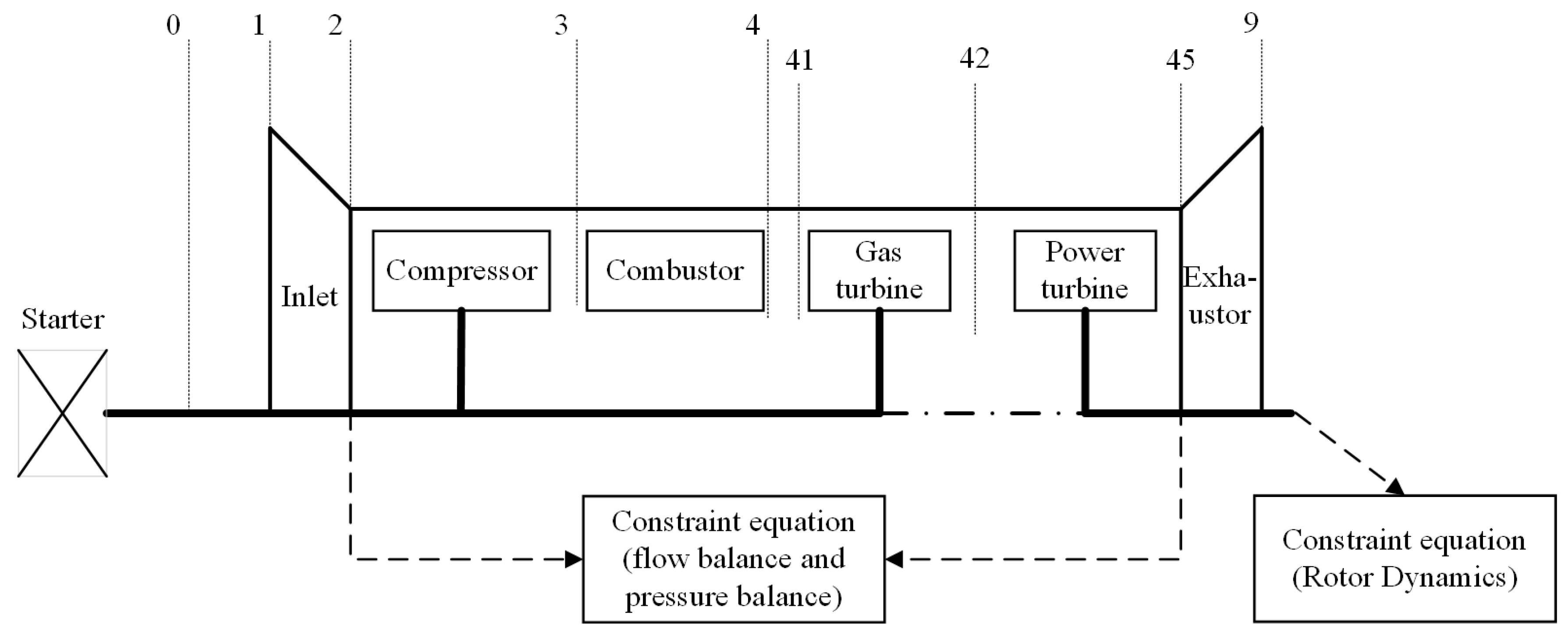
When modeling, first, based on the real structure of the turboshaft engine in the test system, the model is divided into sub-components such as the intake port, compressor, combustion chamber, gas turbine, power turbine and exhaust pipe, as shown in
Figure 3, and the cross-sectional positions of different components are divided. Secondly, each relatively independent component is described, respectively, with the corresponding aerothermodynamic equations. Among them, the compressor, gas turbine and power turbine play a key role in the overall performance of the turboshaft engine, especially involving complex aerothermodynamic processes, and it is particularly necessary to introduce additional characteristic diagrams for description [
32]. However, precise component-level characteristic data is difficult to obtain and is replaced by general characteristic maps during the modeling process. Among them, Section 0: Airflow far in front of the engine; Section 1: Inlet of the air inlet; Section 2: Compressor inlet; Section 3: Compressor outlet/combustion chamber inlet; Section 4: Outlet of the combustion chamber; Section 41: Inlet of gas turbine; Section 42: Gas turbine outlet; Section 45: Power turbine outlet; Section 9: Tail nozzle outlet.
Then, the steady-state co-working equations of each sub-component are established based on the balance of flow rate, pressure and power. Based on the flow rate and pressure balance, and combined with rotor dynamics, a dynamic co-working equation is established. Finally, by using the Newton–Raphson algorithm [
33] to iteratively solve the common working equations, the steady-state model and dynamic model of the turboshaft engine were established, respectively. Among them, the common working conditions that the engine needs to meet to maintain stable operation mainly include:
(1) Gas turbine inlet flow balance;
(2) Inlet flow balance of the power turbine;
(3) Gas pressure balance at the exhaust pipe outlet;
(4) Power balance between the gas turbine and the compressor;
(5) Power balance between the power turbine and the load;
The turboshaft engine under steady state needs to simultaneously meet all the conditions (1) to (5) above. When the turboshaft engine is in a dynamic process, only (1) to (3) needs to be satisfied, but the power balance condition is not met. The power difference among them changes the rotational speed of the rotating components through rotor dynamics.
Based on the real test data of the turboshaft engine in the early stage, comparisons between simulated and experimental data show that the maximum deviation between the two does not exceed 7%, indicating that the simulation model has relatively high accuracy. Data deviations may stem from certain discrepancies between the working characteristics of the components of the real engine and the general characteristic diagrams used in the modeling process, as well as some condition assumptions made during the modeling process. In the future, the model can be iteratively corrected based on the test data to improve its accuracy.
The generator, motor and battery models in the simulation were developed based on the Simscape Electrical Specialized Power Systems (SPSs) components built into the Simulink simulation platform. The generator and motor adopt the Permanent Magnet Synchronous Machine (PMSM) in the SPS library, and the lithium-ion battery is selected for the power battery. The specific parameters of the generator model, the motor model and the power battery model are, respectively, shown in
Table 4,
Table 5 and
Table 6.
The motor and power battery models should also, respectively, include the corresponding AC/DC rectifiers, DC/DC choppers, DC/AC inverters and their control strategies. Among them, insulated gate bipolar transistors (IGBTs) are uniformly selected as switching devices, and the control strategy will be further analyzed in the following text.
3.2. Simulation Analysis
Bus voltage stability is the foundation for the stable operation of DC microgrid systems. This requires that in TSE systems and power battery systems, there must be exactly one energy system responsible for maintaining a constant DC bus voltage. Therefore, the control strategy of the integrated system should include two main forms: “ turboshaft-electric system voltage stabilization” or “power battery voltage stabilization”. Owing to the order-of-magnitude difference in time scales between the turboshaft engine’s thermodynamic system and power-electronic devices, adopting the “turboshaft-electric system voltage stabilization” strategy may prolong transition times during dynamic processes. “Power battery voltage stabilization”, on the other hand, has a faster response speed and is relatively more conducive to enhancing the dynamic stability of the system.
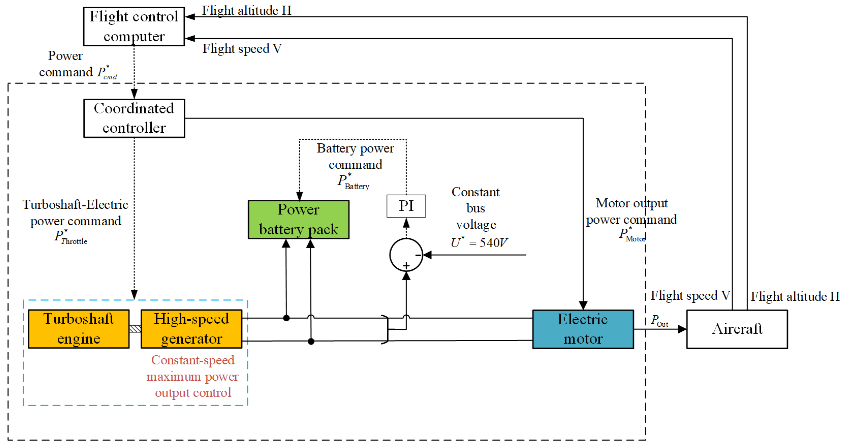
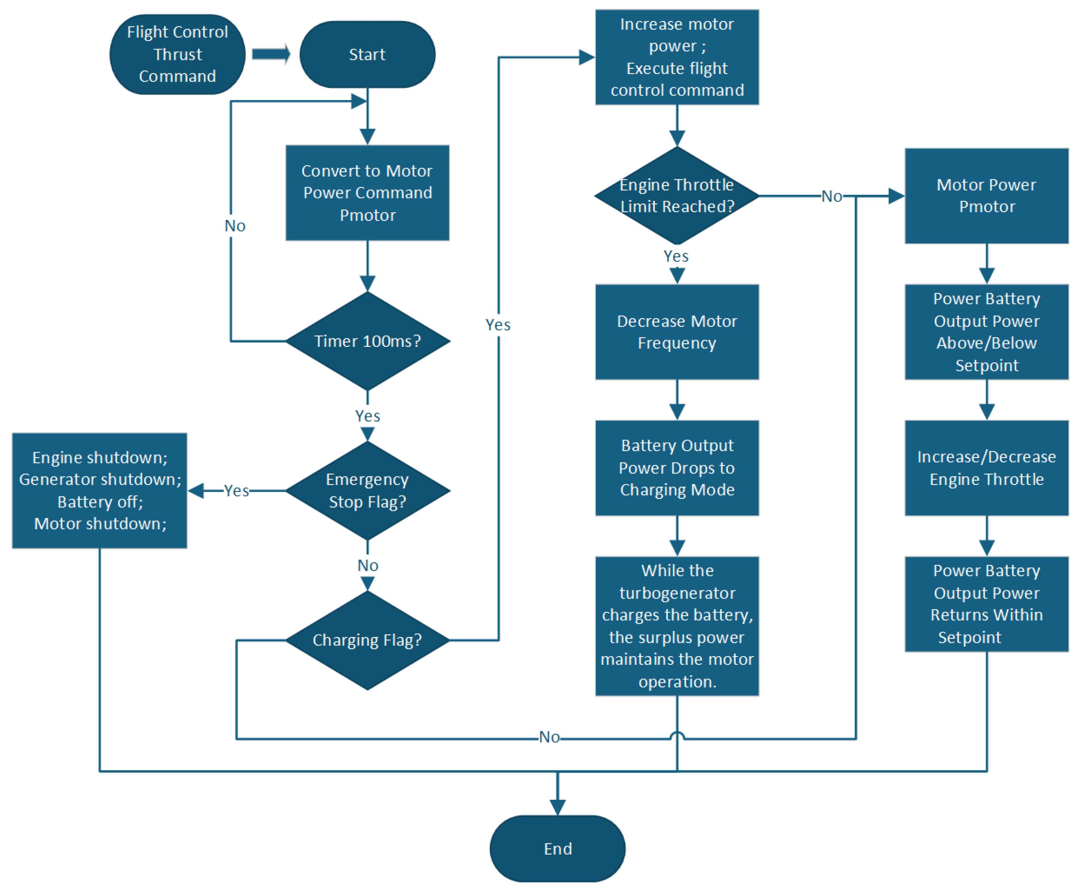
Based on this, the power battery and its DC/DC chopper adopt a double closed-loop Proportional–Integral (PI) control with an outer voltage loop and an inner current loop to maintain a constant bus voltage and have the ability of bidirectional power flow, that is, the ability to switch between charging and discharging states. The TSE system regulates according to the power command. On the one hand, the engine regulates the fuel flow through an open loop. On the other hand, the high-speed generator takes the torque and rotational speed of the engine output shaft as the model input and adopts the control strategy of the outer loop of rotational speed PI and the inner loop of current Finite Control Set Model Predictive Control (FCS-MPC) to efficiently convert mechanical power into electrical power and inject it into the DC microgrid. The control strategy of the integrated system is shown in
Figure 4, and control parameters are shown in
Table 7.
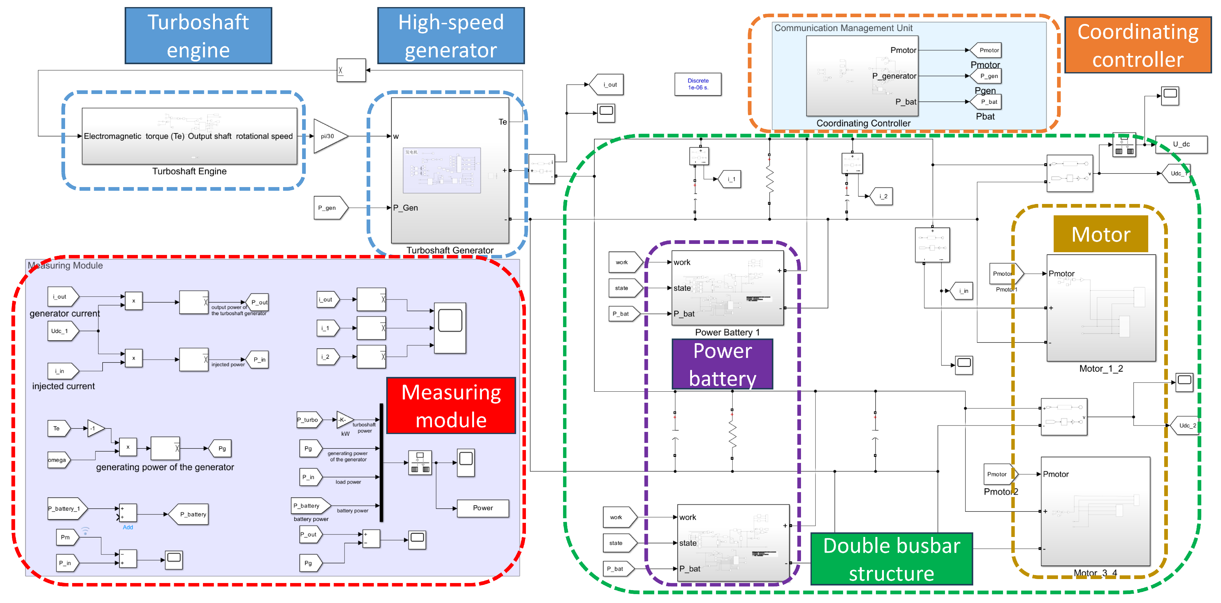
Based on the modeling and design of each main component and its controller, the system adopts the “reverse simulation method”, that is, starting from the required power of the load motor under different working conditions, the working state of the energy system is adjusted in reverse. To sum up, the integrated dynamic simulation model of the 200 kW-class series-connected aviation hybrid electric propulsion system is shown in
Figure 5.
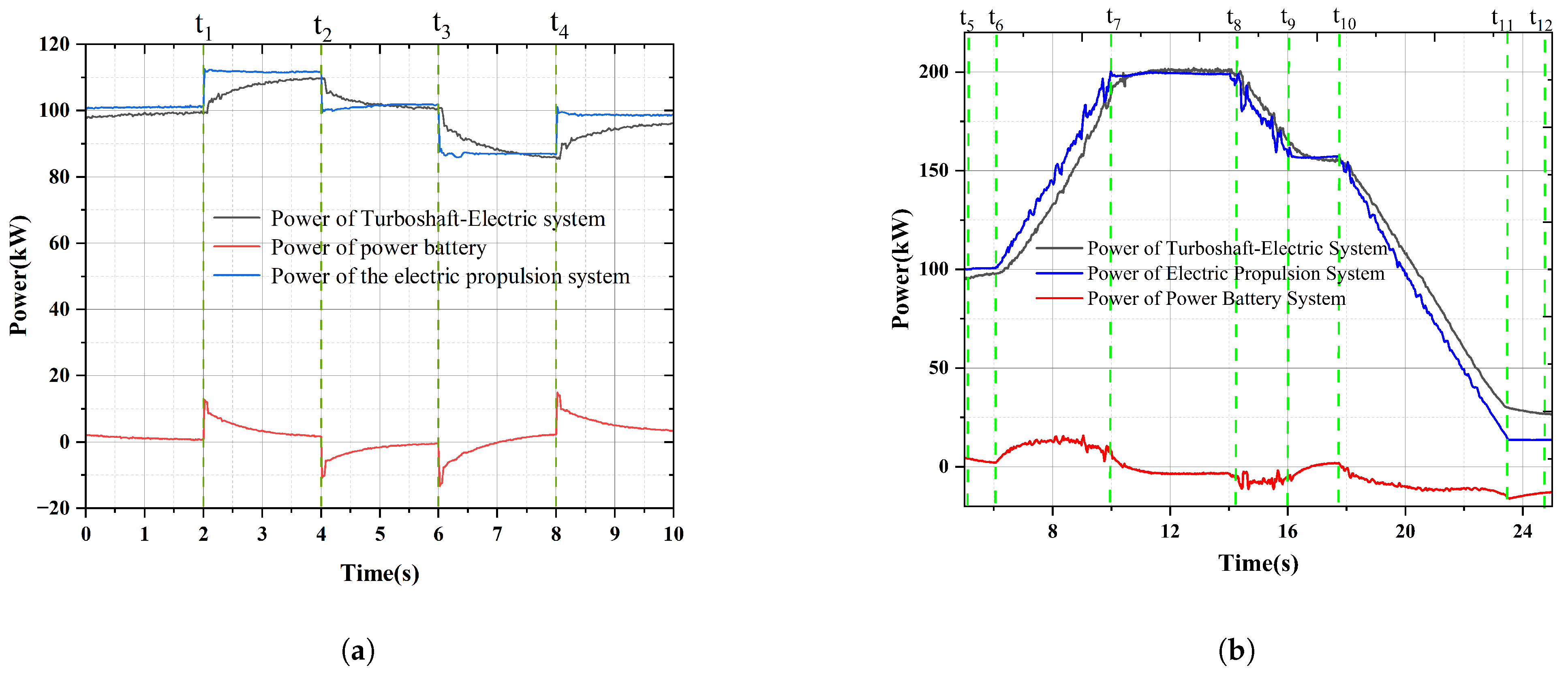
When the motor operates stably with a power output of 105 kW under the predetermined cruising condition, the working status of all components of the system is normal. Suppose the power demand of the load fluctuates by approximately “+10 kW to 0 to −10 kW∼0” to simulate the state changes of the system under sudden disturbances. As shown in
Figure 6a, the power battery pack can quickly track load changes with a near-instantaneous response, while the TSE system is allowed to achieve state regulation for a longer time. Among them, when
= 6 s, the load demand decreases and the generation power is greater than the load power. At this time, the power battery pack absorbs the redundant electrical energy on the DC bus to charge itself, and the power performance is negative, which is in line with the expected design requirements. As shown in
Figure 6b, the hybrid propulsion system switches from the cruise condition to the takeoff condition at
, with the electric motor gradually ramping up to full-power output. At
, it reaches the takeoff condition, i.e., the maximum-power (200 kW) output point. At
, the system transitions to the climb condition, and the power decreases gradually. At
, it arrives at the climb-condition power point (170 kW). At
, the system switches to the idle condition and reaches the idle condition at
.
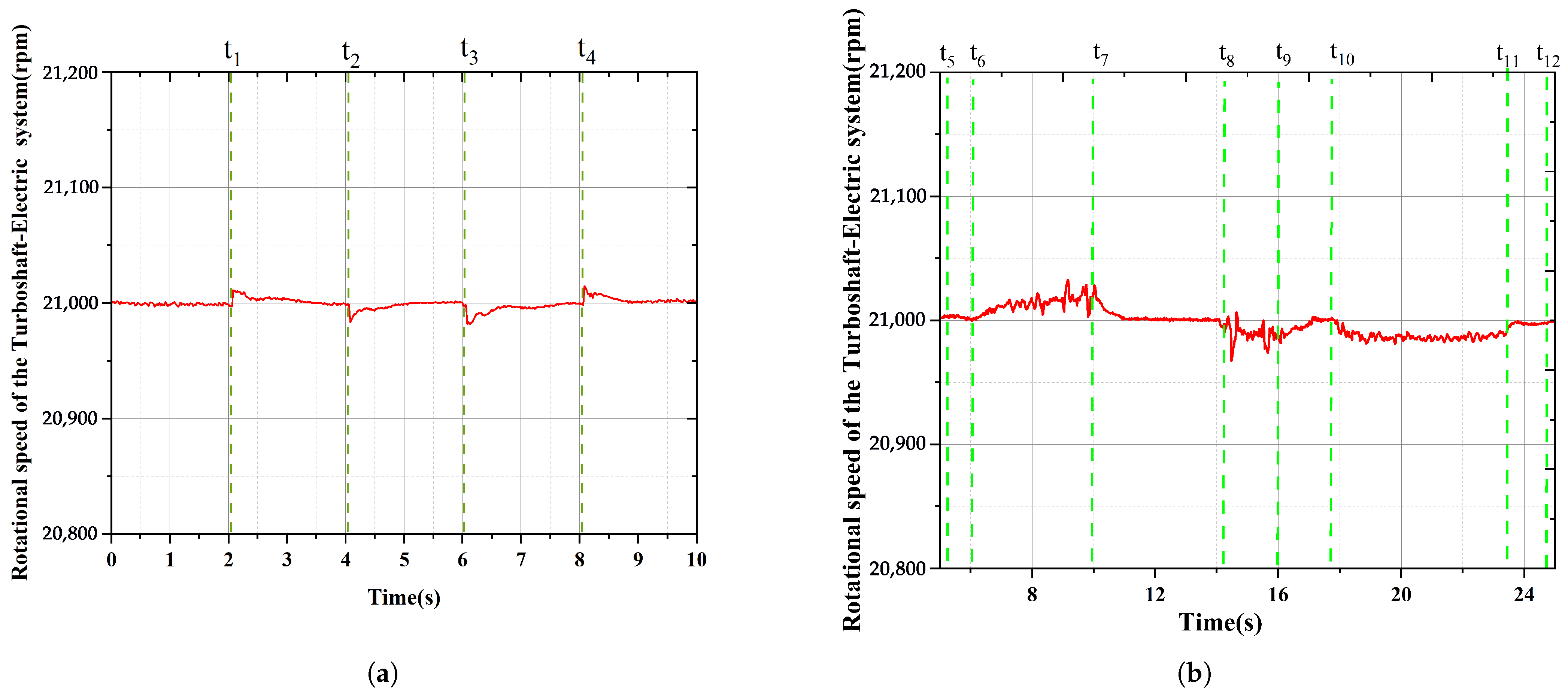
From the perspective of the rotational speed of the TSE system, the rotational speed variation in the system under disturbed conditions mainly stems from the “active” regulation of the fuel flow by the turboshaft engine. For instance, at
= 2 s and
= 4 s, in response to the load change, the turboshaft engine increases or decreases the throttle ratio accordingly, and the unit speed increases or decreases first. Subsequently, constant speed control is carried out by the generator and its AC/DC rectifier. Due to the high control frequency of the generator system, rotational speed variation remained within 0.2%, and the regulation time was less than 1 s, with no obvious fluctuations occurring. The simulation rotational speed curve is shown in
Figure 7a,b.
Overall, based on the control strategy centered on “power battery voltage stabilization” in this chapter, a dynamic simulation model of the 200 kW-class series-connected aviation hybrid electric propulsion system has been established. This model covers multiple subsystems and their control strategies. The simulation results show that this model has a high degree of credibility. The adopted control strategy exhibits robust performance under perturbations, meets the established design requirements, and can be iteratively designed and optimized with the test system.
