Article

Fuel Grain Configuration Adaptation for High-Regression-Rate Hybrid Propulsion Applications

National Key Laboratory of Solid Rocket Propulsion, Northwestern Polytechnical University, Xi’an 710072, China
*
Author to whom correspondence should be addressed.
Aerospace 2025, 12(8), 652; https://doi.org/10.3390/aerospace12080652
Submission received: 11 June 2025 / Revised: 13 July 2025 / Accepted: 18 July 2025 / Published: 23 July 2025

Abstract

Low regression rate is the most critical issue for the development and application of hybrid rocket motors (HRMs). Paraffin-based fuels are potential candidates for HRMs due to their high regression rates but adding polymers to improve strength results in insufficient regression rates for HRMs applications. In this work, Computational Fluid Dynamics (CFD) modeling and analysis were used to investigate the mixing and combustion of gaseous fuels and oxidizers in HRMs for various fuel grains and injector combinations. In addition, the regression rate characteristics and combustion efficiency were evaluated using a ground test. The results showed that the swirling flow with both high mixing intensity and high velocity could be formed by using the swirl injector. The highest mixing degree attained for the star-swirl grain and swirl injector was 86%. The reported combustion efficiency calculated by the CFD model attained a maximum of 93% at the nozzle throat. In addition, a spatially averaged regression rate of 1.40 mm·s−1 was achieved for the star-swirl grain and swirl injector combination when the mass flux of N2O was 89.94 kg·m−2·s−1. This is around 191% higher than the case of non-swirling flow. However, there were obvious local regression rate differences between the root of the star and the slot. The regression rate increase was accompanied by a decrease in the combustion efficiency for the strong swirling flow condition due to the remarkable higher mass flow rate of gasified fuels. It was shown that the nano-sized aluminum was unfavorable for the combustion efficiency, especially under extreme fuel-rich conditions.

1. Introduction

The hybrid rocket motors (HRMs) concept was first conceptualized in 1937, with its inherently separable oxidizer and fuel components delivering remarkable safety and reliability, while the flowability of the liquid oxidizers enables superior excellent re-start and throttling abilities. Therefore, HRMs are considered as an optimal energy source for aerospace propulsion [1,2]. However, the development and applications of HRMs have long been hampered by a low regression rate and reduced combustion efficiency, which is primarily attributed to both inert polymer fuels and large-scale diffusion combustion [3].
The regression rate of polymer fuels is controlled mainly by the heat transfer to the fuel surface due to the gasification mass transfer mechanism. The tangential velocity component of swirling flow could increase the turbulence intensity, facilitating the mixing and combustion of the gasified fuel and oxidizer. At the same time, the centrifugal force caused by the swirling motion of the oxidizer flow made the oxidizer closer to the combustion surface, compressing the boundary layer and thus bringing the flame closer to the combustion surface [4]. Therefore, the swirling flow in the fuel grain port could increase the regression rate significantly through heat transfer enhancement [5]. The swirling injector is the most common method for swirling flow formation. Yuasa et al. conducted experiments by installing a swirling injector at the front of the fuel grain and found that the PMMA combustion rate using the swirling injector was 2.7 times faster than axial injection under the same conditions [6]. Summers et al. investigated the effect of the parameters of the swirling injector on the regression rate of the grain, and the results showed that a larger angle degree had a more obvious effect on the regression rate. Additionally, a larger swirl number resulted in a more uniform regression rate along the axial combustion surface [7]. The swirling injector is the most common method for swirling flow formation, but the swirling intensity decreases along the flow path due to the viscosity force and wall friction [5].
Swirling intensity at various axial locations of fuel grain can be maintained by adopting special port geometry, such as helical grain, nested helical grain, and star-swirl grain [8,9,10,11]. Multi-section swirl injection is another effective means to maintain the swirling intensity in the fuel port, but it forces high requirements on the mechanical properties of the fuel [12,13]. As well as maintaining the swirling intensity, vertex hybrid motors have the capability of increasing the oxidizer residence time. This has an outstanding impact on the regression rate and combustion efficiency [14]. In addition, the regression of polymer fuels is formed by the thermal decomposition, so additives that are in favor of the process can also improve the regression rate to some extent [15,16]. The regression rate of HTPB fuel is enhanced by 15.5% when 5% nickel acetylacetonate is added at Gox = 50 kg·m−2·s−1. However, the addition of catalyst had limited effect on the enhancement of the thermal decomposition rate of the polymer. Thus, further improvements in the regression rate of the grain are still required.
The droplet entrainment mass transfer mechanism gives paraffin fuels a regression rate that is 3~4 times higher than classical polymer fuels [17,18]. In this regard, paraffin/polymer blends with excellent mechanical properties are recommended for practical purposes with demonstrated positive impacts [19]. However, the regression rate of these paraffin-based fuels is still not enough to fully satisfy the requirements of HRMs, mainly due to the addition of the polymer [20,21]. Both gasification and droplet entrainment are the main mass transfer mechanisms of paraffin-based fuels, with the droplet entrainment controlled by the instability of sheared melting film subject to blowing. Therefore, most of the regression rate improvement methods mentioned above for polymer fuels should also be applied to paraffin-based fuels because entrained droplets are easier to generate with elevated turbulence intensity [22].
Helical port geometries effectively mitigate the attenuation of swirling oxidizer flow, thereby enhancing the fuel regression rate. While existing literature has confirmed that swirl-enhancing grain configurations improve regression rates under the swirl injector [23,24,25], most of these studies have been conducted on a particular fuel configuration. Computational Fluid Dynamics (CFD) plays an important role in the flow field analysis of aerospace propulsions [26,27]. So, fuel grains with different port geometries and two injectors are used to evaluate the mixing and combustion characteristics by employing CFD modeling and analysis in this work, and the fuel grain optimization is carried out based on the streamline optimization technique. In addition, the regression rate of the paraffin-based fuel with star-swirl geometry is investigated through an HRM ground test. The results of this study could provide useful information to enhance the combustion performance of HRMs.

2. Streamline Optimization Based on CFD

2.1. CFD Analysis

CFD modeling and numerical simulations were carried out to investigate the mixing and diffusion combustion characteristics of the oxidizer with gasified fuels in HRMs. This CFD modeling and analysis will then guide the optimization of the motor design based on the improvement of both the regression rate and combustion efficiency. The swirl injector creates an additional tangential velocity component besides the axial one related to the convention showerhead injectors in HRMs. This, in turn, enhances the mixing and heat transfer. Therefore, a swirl injector with four holes was used in this work to create enough swirl intensity for the oxidizer flow. The structure of the considered swirl injector is shown in Figure 1.
The swirl strength of the gas flowing through the swirl injector decreases gradually along the length of the motor due to the gas viscosity and rough burning surface. In addition, the combination of a fuel grain port configuration and the swirl injector may effectively regulate the gas flow line and improve the gas swirl strength in the whole combustion chamber. Therefore, three fuel grains with different swirl effects were considered in this study and compared to a single port fuel tube grain using numerical calculations. The different fuel grain configurations considered in this work are shown in Figure 2.
The Reynolds equations for a single-phase multicomponent turbulent reacting flow were solved by employing a control-volume-based technique and a pressure-based algorithm. The Favre-averaged (i.e., density-weighted) equations of continuity and momentum were expressed in the Cartesian tensor form, and the gases in the combustion chamber were assumed to behave as an ideal gas. Meanwhile, the gas-governing equations coupling the three-dimensional Navier–Stokes equations with turbulence equations and transport equations were implemented:
ρ t + x i ρ u i = 0
t ρ u i + x i ρ u i u j = P x i + x i τ i j
t ρ e t + x i ρ h t u j = x i τ i j u i q i
ρ Y i t + x i ρ u j Y i = x i ρ u i Y i + ω i
In this study, the k-ω SST turbulence model was used. The derivative term of the transverse dissipation was added to the k-ω SST turbulence model, and the transfer process of the turbulent shear stress was considered. Thus, the model could calculate jet flow, swirling flow, wall-confined flow, and free shear flow more accurately. The turbulent kinetic energy k and the specific dissipation rate w can be obtained by the following turbulence governing equations:
t ρ k + x i ρ k u i = x j Γ k k x j + G ˜ k Y k + S k
t ρ ω + x i ρ ω u i = x j Γ ω w x j + G ˜ ω Y ω + D ω + S ω
where G ˜ k and G ˜ ω represent the development of turbulent kinetic energy due to gradients of mean velocity and generation of ω, Γ k and Γ ω represent the diffusivity of k and ω, respectively, Y k and Y ω show the dissipation of k and ω due to turbulence, and D ω represents the cross-diffusion term.
For the purposes of the simulation, it was assumed that the fuel consisted of only HTPB and paraffin. Published experimental findings in previous studies have indicated that 1,3-butadiene (C4H6) is the major component of the HTPB pyrolysis product. Paraffin consists of mixed saturated alkanes with a combustion process similar to that of ethylene (C2H4). In this work, only the gas-phase reaction was considered in the numerical model. Furthermore, O2, C4H6, and C2H4 were considered as the gas-phase reactants to simplify the calculations and the analysis.
The chemical reaction process of hydrocarbon fuel gases involved two global reaction steps [28], as shown below:
C4H6 + 3.5O2 → 4CO + 3H2O
C2H4 + 2O2 → 2CO + 2H2O
CO + 0.5O2 ↔ CO2
The non-premixed combustion of C4H6 and C2H4 with oxygen was modeled by using the Eddy dissipation (ED) model, coupled to the chemical equilibrium. The enhanced wall treatment was employed as a turbulence boundary condition on the burning surface. Three-dimensional unstructured grids were used in the calculation due to the non-axial symmetry of the injector and the fuel grains. The physical model and boundary of the combination of the swirl injector and tube grain are shown in Figure 3a. The methodology employed in this study has been rigorously validated against published literature, demonstrating an acceptable level of deviation in comparative analyses [29].
The oxygen inlet, the burning surface with a length of 0.25 m, and the gas outlet were defined as the oxygen mass flow inlet, fuel gases mass flow inlet, and the pressure outlet, respectively. The mass flow rate of oxygen was 60 g/s, with a temperature of 298 K. The gas product formed on the surface of the fuel grain had an initial temperature of 700 K. and a mass flow rate of 17 g/s. This was a mixture of C2H4 and C4H6 in a ratio that corresponds to the paraffin-based fuel. The nozzle exit pressure was fixed at 1 atm. All the walls were assumed to be adiabatic and no-slip walls. The regression of the fuel was ignored, and steady gas flow and combustion were assumed in the calculations.
The mixing degree ηr is an important parameter to characterize the mixing effect of the oxidizer with fuel gases. This mixing degree can thus be defined as the ratio of the local fuel gases’ mass fraction Yr at the center point of the grain port outlet (i.e., x = 0.3 m, y = 0) to the fuel gases’ mass fraction Y with complete mixing. The mixing degree can be expressed by Equation (10):
η r = Y r Y × 100 %
Three different grids were considered for the grid sensitivity analysis, and the combustion case combining a swirl injector with a tube grain was selected for this purpose. The coarse grid (20,512 cells) and the fine grid (464,128 cells) were obtained by halving and doubling the number of cells in all directions with respect to the reference grid (164,096 cells), respectively. The numerical results of temperature and O2 mass fraction are shown in Figure 4. Additionally, the error ε was evaluated by calculating the asymptotic value according to the Richardson extrapolation procedure with n = 2, which can be described as:
γ RE = γ fine + γ fine γ medium n 2 1
ε = γ γ RE γ RE
where γ represents the common variable. The numerical errors of temperature and combustion efficiency are shown in Figure 5.
Figure 4 shows that both the radial profiles of temperature and the axial profiles of O2 mass fraction were presented as monotonic convergence, and grid-independent solutions were obtained when the grid had 164,096 cells, with variations between the medium and fine mesh of less than 1%. Additionally, Figure 5 indicates that the numerical error reduced roughly following the spatial order of accuracy of the scheme. Therefore, the size of the grid with 164,096 cells is considered acceptable for the cases.

2.2. Non-Reactive Mixing Intensity for Various Grain Configurations

The effective mixing of the gasified fuels and the oxidizer is very important for the large-scale diffusion combustion of HRMs, which could be associated with the flow velocity. The oxygen mass fraction and the flow velocity information of the non-reactive flow for various grain configurations are shown in Figure 6.
Moreover, Figure 6 presents the evolution of the oxygen fraction and the velocity distribution of the internal flow field. As shown in the figure, the oxygen fraction decreased gradually in the direction of the flow due to the constant mass addition of fuel. Both the mixing intensity and the velocity could be enhanced significantly for the swirling flow cases, accompanied by a low velocity of the oxygen mainstream (core of flow). In addition, a classical boundary layer was presented in the fuel port for the tube grain combined with a direct injector due to the single axial velocity component.
The mixing effect could be evaluated through the radial distribution of oxygen at the tail end of fuel grains, which is shown in Figure 7. The abbreviations used in the figure legend are as follows: TG, tube grain; SG, star-swirl grain; HG, helical grain; CSG, circular-swirl grain. The dotted lines represent the symmetry axis at the ports’ exit planes.
Generally, the oxygen mass fraction should not change with the radial position during the intensive mixing process, i.e., the oxygen could mix with the fuel completely. Figure 7 indicates that there was a remarkable change in the oxygen mass fraction of the various radial positions. In this regard, a low mixing degree of around 17% was achieved due to the weak mass transfer in the classical boundary layer when the tube grain combined with a direct injector was used, which was unfavorable for the efficient combustion of the motor. The mixing degree in the port of the tube grain increased drastically to 73% when the tube grain combined with the swirl injector was employed, which showed the remarkable mixing effects of the swirling flow. It is shown that the helical groove was favorable for maintaining the swirling intensity in the fuel port, but the groove kept some part of the gaseous fuel away from the oxygen mainstream in the cases of helical grain in this study. This resulted in a mixing degree of 64%, which was lower than the reported mixing degree in the case of the tube grain. In fact, a higher mixing degree should be achieved for helical grain if the port area is similar to the tube one. The highest mixing degree reported for the star-swirl grain was around 86%, due to the provided maintenance of the swirl intensity as well as the lower diffusion scale (lower port area).
Figure 8 shows the flow velocity along the radial direction at the tail end of the fuel grains.
As shown in the figure, the reported flow velocity was low, especially near the burning surface in the case of the tube grain combined with the direct injector, which was largely responsible for the low mixing intensity. In addition, the swirling flow could increase the flow velocity near the burning surface remarkably when the swirl injector was used, which was very useful for the mixing due to the large Reynolds number attained. In addition, an “M-shaped” flow velocity distribution was formed for the tube grain and the helical grain under the swirl injection, and the higher flow velocity for the tube grain was also due to the lower port area. Although the maximum flow velocity (75 m·s−1) for the case of the star-swirl grain was lower than that of the tube grain (90 m·s−1), the overall flow velocity was the highest, where the minimum flow velocity was as high as 57 m·s−1. Therefore, the star-swirl grain seems to be the optimal fuel grain configuration from the aspect of mixing intensity.

2.3. The Reacting Flow of Star-Swirl Grain Combined with a Swirl Injector

Both chemical reaction and diffusion processes are important constituent elements in the combustion of HRMs. In this regard, Figure 9 shows the temperature and the oxygen mass fraction distribution for the star-swirl grain combined with the swirl injector, taking the chemical reactions into account. The results for the tube grain combined with the direct injector were used for comparison with this scenario.
It can be seen from Figure 9 that the oxygen was continuously consumed along the flow direction, and there was still a certain amount of unconsumed oxygen even at the nozzle throat in the case of the tube grain combined with the direct injector, resulting in poor combustion performance of the motor. On the other hand, an intense swirling flow could be formed and maintained in the case of the star-swirl grain combined with the swirl injector. Then, almost all the oxygen was consumed with the temperature rising to 2700 K in the aft mixing chamber. In addition, the temperature distribution in various axial positions of fuel grain ports is shown in Figure 10.
Figure 10 indicates that the temperature distribution without the swirling flow represented a distinct regular ring-like configuration, and low-temperature zones were located near both the burning surface and the oxygen mainstream. This aligns very well with the classical boundary layer combustion theory. In addition, the region of the oxygen mainstream was gradually reduced with the development of the boundary layer. The swirl intensity in the slot decreased due to the large pitch of the star-swirl grain, which would weaken the mixing degree of the oxygen and fuels, resulting in a lower combustion temperature. The highest temperature was reported at the circular region near the root of the star due to the optimal oxygen–fuel ratio and the high swirl intensity, which was similar to the boundary layer combustion. The combustion efficiency at the nozzle throat was about 66% and 93% for the two combinations, respectively. This demonstrates a promising combustion performance enhancement of the star-swirl grain when combined with the swirl injector.

3. Regression Rate of Star-Swirl Grain

3.1. HRM Ground Test

The regression rate of solid fuels can be evaluated only by the HRM ground test, and the facility used in this study was inspired by the setup presented by Liu et al. in a previous study [20]. The structure of the thrust chamber is presented in Figure 11.
Liquid nitrous oxide was stored in a 3 L stainless-steel tank, and three bottles of high-pressure nitrogen were used to provide a steady boost pressure of about 7 MPa for the supply of nitrous oxide. The mass flow rate of nitrous oxide was controlled by the venturi tubes with different throat diameters. The star-swirl fuel grain combusted with nitrous oxide in the combustion chamber with black powder as the ignition source. The combustion time was set as 20 s, and thus the regression rate could be obtained by the mass and the port diameter changes of the fuel grains. In addition, the chamber pressure was maintained at around 3 MPa by adjusting the nozzle of the thrust chamber. The grains were removed at the end of the combustion process, after which the regression rate was evaluated using both the average and local measurements. The average regression rate was derived from the equivalent port diameters (d0 and d1) calculated using pre- and post-combustion mass differences, divided by the burning time. Local regression rates were determined by axially sectioning the combusted grain. Thin slices were cut off from half fuel grains, and the residual thickness of solid fuel was obtained using point-by-point mapping [20].
The ingredients of the baseline formulation in this study were the same as the ones used in the authors’ previous study, namely, solid paraffin at 38 wt%, liquid paraffin at 28 wt%, improved PE at 4 wt%, HTPB matrix at 15 wt%, aluminum with a particle size of 10 μm at 10 wt%, and magnesium with a particle size of 1 μm at 5 wt% [20]. To improve the regression rate further, another formulation where 1% micron-sized aluminum was replaced by 80 nm aluminum was also prepared. Aluminum was introduced into the fuel for the experimental tests. The advantages of aluminum include a high calorific value of combustion, high density, and the condensed-phase combustion products with greater emissivity. Adding aluminum to fuel increases its energy density and improves heat transfer from high-temperature gases to the combustion surface, which can enhance the combustion surface retreat rate.

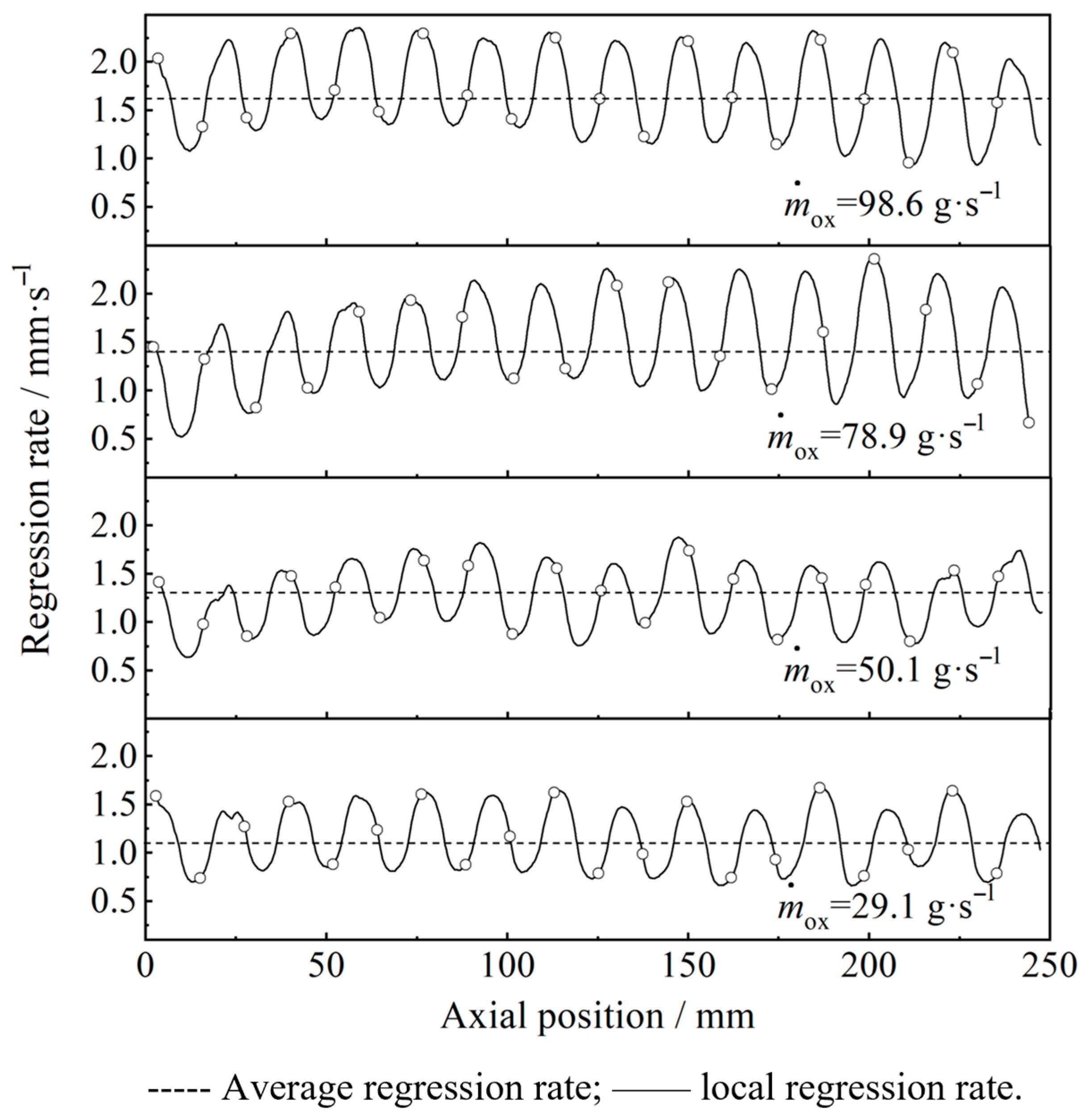
3.2. Local Regression Rate Characteristics

Figure 12 shows the typical axial view of the split-baseline paraffin-based fuel grains after the ground test.
As shown in Figure 12, the local regression rates of both grains remained nearly invariant for various axial positions in general, which was advantageous to the full utilization of the fuel. The local regression rate of the tube grain decreased with the increasing axial position. During combustion, the regression rate was higher at the fore end and lower at the aft end. For the star-swirl grain, the port diameter variation along the axial distance exhibited a trend of initial increase, followed by a decrease, and a final increase. This effect was due to the smaller oxygen-to-fuel ratio, the weakened swirling intensity of the flow, and the accumulation of fuel at increasing axial distances. Apart from the axial ablation, there was an apparent spiral for the port of star-swirl grain, indicating regular combustion. However, there were obvious local regression rate differences between the root of the star and the slot. The local regression rate of various axial positions was obtained through the point-by-point mapping of the burning surface and is reported in Figure 13.
Figure 13 shows a remarkable fluctuation for the local regression between the root of the star and the slot, with a higher regression rate at the slot mainly due to the lower swirl intensity. Driven by swirling oxidizer flow entering the port, an oxygen-rich combustion zone formed near the root of the star at the grain head, where the cold oxidizer flow suppressed the regression rate. As the oxidizer was progressively consumed and heated, an optimal oxidizer-to-fuel (O/F) ratio was achieved downstream of the head section, resulting in maximum regression rate. Beyond this point, decreasing the oxidizer fraction and increasing the gas fraction within the root of the star transitioned the flow to fuel-rich conditions. The rate of regression of the fuel was reduced. The regression rate increased at both the root of the star and the slot when the oxidizer mass flow rate was increased, but the regression rate fluctuation appeared to increase at first and then decrease. The maximum difference in the regression rate for the neighbor root of the star and the slot was reported as 1.4 mm·s−1 under an oxidizer flow rate of 78.9 g·s−1. This was close to the averaged regression rate value, and this difference should be addressed in the port geometry design. In addition, it is noted that the fluctuation was irregular for different axial positions, which may be attributed to the complex flow and combustion processes.

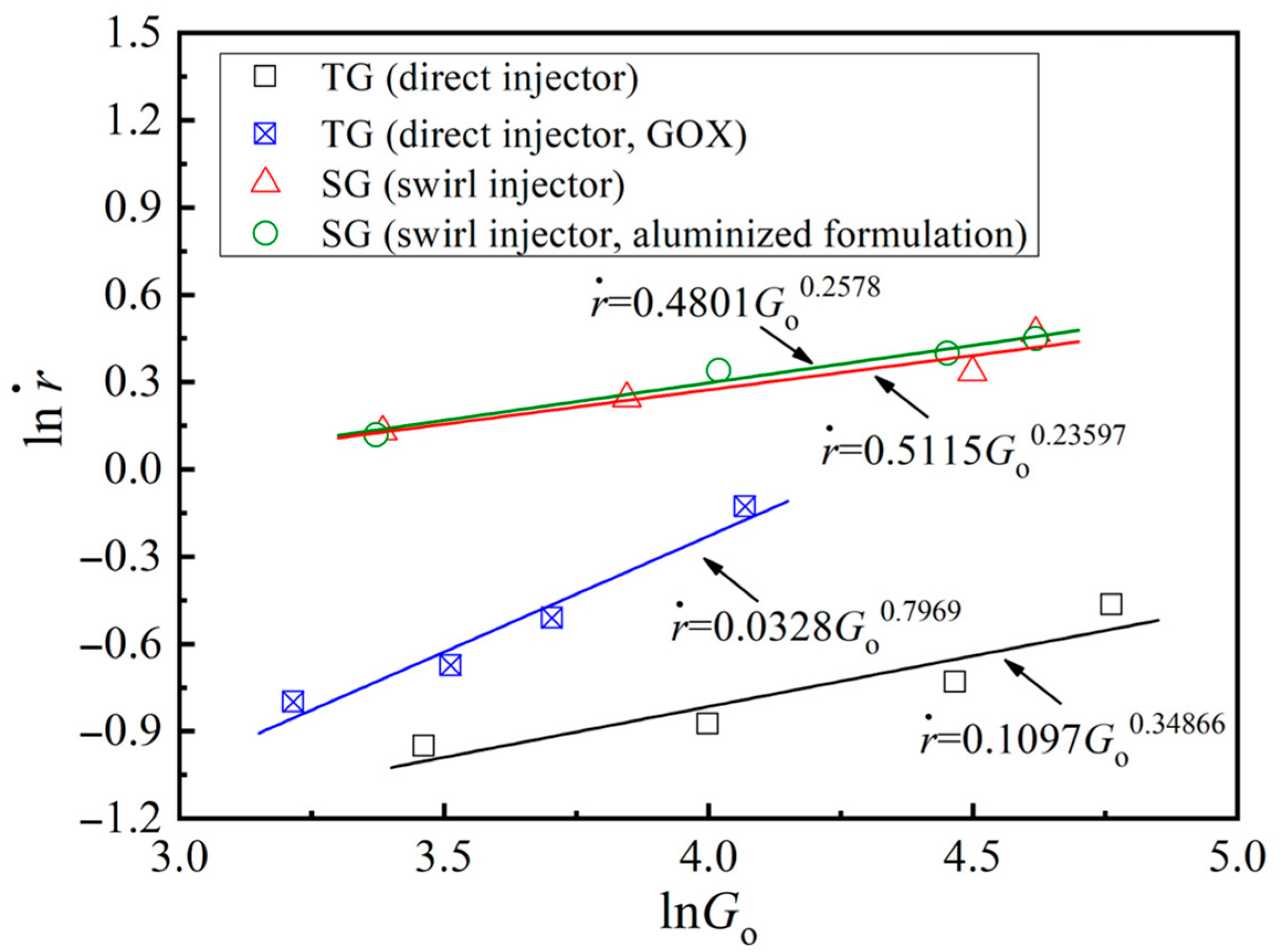
3.3. Spatially Averaged Regression Rate Characteristics

The spatially averaged regression rate could be evaluated by the mass difference between the unburned and burned fuel grains. In general, the relationship between the regression rate and the oxidizer mass flux Go can be expressed by the following empirical formula:
r ˙ = a G o n
where a is the regression rate constant and n is the exponent. The values of a and n could be obtained by fitting the regression rate under different oxidizer mass fluxes. Go can be calculated by using Equation (14):
G o = m ˙ A b
where m ˙ is the mass flow rate of the oxidizer and Ab is the port area of the fuel grain.
In this study, nitrous oxide was used as the oxidizer. As it possesses a low oxygen content, the motor has a high oxygen-to-fuel ratio, which means that the fuel has minimal impact on the oxidizer mass flux. Additionally, uneven regression rates occurred throughout the combustion process due to the addition of axial mass, but the effect was not particularly noticeable in our experimental observations. The empirical Formula (10) maintains applicability under widely varying flow conditions and thus remains valid for the present investigation. The spatially averaged regression rates of various operating conditions are shown in Figure 14.
Figure 14 highlights a significant regression rate increase by using GOX (gaseous oxygen) as the oxidizer, mainly due to the low oxygen content and the low reactivity of N2O. The reported regression rate increase was about 109%, with Go = 58.54 kg·m−2·s−1. In addition, a regression rate of 1.40 mm·s−1 was achieved for the star-swirl grain and the swirl injector combination when the mass flux of N2O was 89.94 kg·m−2·s−1, which was about 191% higher than the case of the tube grain and the direct injector combination. This means that swirling gas enhanced the thermal feedback from the flame to the combustion surface as well as mass addition, resulting in a significant increase in the regression rate. In addition, the combustion efficiency (c* efficiency) decreased from 83.33% to 75.42% when the mass flux of N2O was increased from 29.49 kg·m−2·s−1 to 101.36 kg·m−2·s−1 for the star-swirl grain and swirl injector combination. This could be attributed to the lower reaction time under higher flow velocity. Similarly, the combustion efficiency decreased from 85.51% to 79.00% when the mass flux of N2O was increased from 29.10 kg·m−2·s−1 to 110.52 kg·m−2·s−1 for the tube grain and direct injector combination. Swirl combinations had lower combustion efficiencies compared to direct combinations, suggesting that an increase in the regression rate was accompanied by a decrease in combustion efficiency even under the strong swirl flow condition. The swirl flow was beneficial to the combustion efficiency through the enhancement of the mixing in general, but the remarkable higher mass flow rate of the gasified fuels resulting from the higher regression rate was unfavorable for the combustion.
Generally, the regression rate is supposed to increase when metal particles are added to solid fuels because the condensed-phase combustion products could improve the heat transfer from the flame to the burning surface through higher radiation heat transfer. But, as reported in Figure 14, there was only a slight increase in the regression rate when nano-sized aluminum was employed, which may be due to the low concentration. For instance, the regression of the aluminized fuel was 1.49 mm·s−1 when the mass flux of N2O was 85.79 kg·m−2·s−1, about 10.4% higher than that of the baseline formulation. In addition, the combustion efficiency decreased slightly from 76.01% to 71.74% when the mass flux of N2O was increased from 29.13 kg·m−2·s−1 to 101.34 kg·m−2·s−1 for the aluminized formulation. This indicates that there was a lower oxidizer utilization efficiency for the extreme fuel-rich system (lower N2O mass flux), in addition to more incomplete combustion caused by the use of metal particles.

4. Conclusions

In this paper, the mixing effects and the regression rate characteristics for various combinations of fuel gains and injectors were investigated, and the following specific conclusions were drawn:
(1)
The star-swirl grain and swirl injector combination attained the highest mixing degree of 86% in CFD simulations, resulting from sustained swirl intensity and a lower diffusion scale. This configuration delivered 93% combustion efficiency at the nozzle throat, contrasting sharply with the 66% efficiency of the tube grain and direct injector under the same conditions.
(2)
The swirling flow with both high mixing intensity and high velocity could be formed by using the swirl injector, which would increase the mixing degree of the gaseous fuel and the oxidizer significantly. Experimental evidence confirmed that the grain configuration maintained the swirling intensity post-combustion, which was also beneficial for the mixing.
(3)
A spatially averaged regression rate of 1.40 mm·s−1 was achieved for the star-swirl grain and the swirl injector combination when the mass flux of N2O was 89.94 kg·m−2·s−1. This was about 191% higher than the case of the tube grain and the direct injector combination. However, there were obvious local regression rate differences between the root of the star and the slot, which should be addressed in the port geometry design.
(4)
It was shown that the enhancement in the regression rate was accompanied by a decrease in the combustion efficiency for the strong swirl flow condition due to the remarkable higher mass flow rate of the gasified fuels. In addition, nano-sized aluminum could enhance the regression rate but would result in lower combustion efficiency, especially for extreme fuel-rich conditions.

Author Contributions

Conceptualization, L.-L.L. and S.-Q.H.; methodology, L.-L.L. and B.-B.L.; validation, L.-L.L. and Z.-X.C.; formal analysis, L.-L.L.; investigation, L.-L.L. and B.-B.L.; resources, L.-L.L.; data curation, B.-B.L.; writing—original draft preparation, L.-L.L.; writing—review and editing, L.-L.L.; visualization, B.-B.L. and Z.-X.C.; supervision, L.-L.L. and S.-Q.H.; project administration, L.-L.L.; funding acquisition, L.-L.L. All authors have read and agreed to the published version of the manuscript.

Funding

This research was funded by the National Natural Science Foundation of China, grant numbers 51976175 and 51606157.

Data Availability Statement

The original contributions presented in the study are included in the article. Further inquiries can be directed to the corresponding author.

Conflicts of Interest

The authors declare no conflicts of interest.

References

  1. Davydenko, N.A.; Gollender, R.G.; Gubertov, A.M.; Mironov, V.V.; Volkov, N.N. Hybrid Rocket Engines: The Benefits and Prospects. Aerosp. Sci. Technol. 2007, 11, 55–60. [Google Scholar] [CrossRef]
  2. Sun, X.; Tian, H.; Li, Y.; Yu, N.; Cai, G. Regression Rate Behaviors of HTPB-Based Propellant Combinations for Hybrid Rocket Motor. Acta Astronaut. 2016, 119, 137–146. [Google Scholar] [CrossRef]
  3. Marquardt, T.; Majdalani, J. Review of Classical Diffusion-Limited Regression Rate Models in Hybrid Rockets. Aerospace 2019, 6, 75. [Google Scholar] [CrossRef]
  4. Yuasa, S.; Ide, T.; Masugi, M.; Sakurai, T.; Shiraishi, N.; Shimada, T. Visualization of Flames in Combustion Chamber of Swirling-Oxidizer-Flow-Type Hybrid Rocket Engines. J. Therm. Sci. Technol. 2011, 6, 268–277. [Google Scholar] [CrossRef]
  5. Kumar, C.P.; Kumar, A. Effect of Swirl on the Regression Rate in Hybrid Rocket Motors. Aerosp. Sci. Technol. 2013, 29, 92–99. [Google Scholar] [CrossRef]
  6. Yuasa, S.; Yamamoto, K.; Hachiya, H.; Kitagawa, K.; Oowada, Y. Development of a small sounding hybrid rocket with a swirling-oxidizer-type engine. In Proceedings of the 37th Joint Propulsion Conference and Exhibit, Salt Lake City, UT, USA, 8–11 July 2001. [Google Scholar] [CrossRef]
  7. Summers, M.H.; Dennis, J.D.; Villarreal, J.K. Small-Scale Hybrid Rocket Test Stand & Characterization of Swirl Injectors. In Proceedings of the 49th AIAA/ASME/SAE/ASEE Joint Propulsion Conference, San Jose, CA, USA, 14–17 July 2013. [Google Scholar] [CrossRef]
  8. Tian, H.; Li, Y.; Li, C.; Sun, X. Regression Rate Characteristics of Hybrid Rocket Motor with Helical Grain. Aerosp. Sci. Technol. 2017, 68, 90–103. [Google Scholar] [CrossRef]
  9. Wang, Z.; Lin, X.; Li, F.; Yu, X. Combustion Performance of a Novel Hybrid Rocket Fuel Grain with a Nested Helical Structure. Aerosp. Sci. Technol. 2020, 97, 105613. [Google Scholar] [CrossRef]
  10. Zhang, S.; Hu, F.; Zhang, W. Numerical Investigation on the Regression Rate of Hybrid Rocket Motor with Star Swirl Fuel Grain. Acta Astronaut. 2016, 127, 384–393. [Google Scholar] [CrossRef]
  11. Tian, H.; Jiang, X.; Lu, Y.; Liang, Y.; Zhu, H.; Cai, G. Numerical Investigation on Hybrid Rocket Motors with Star-Segmented Rotation Grain. Aerospace 2022, 9, 585. [Google Scholar] [CrossRef]
  12. Vignesh, B.; Kumar, R. Effect of Multi-Location Swirl Injection on the Performance of Hybrid Rocket Motor. Acta Astronaut. 2020, 176, 111–123. [Google Scholar] [CrossRef]
  13. Dubey, A.; Kumar, R.; Biswas, S. Performance estimation of hybrid rocket by varying the flow rate at multi-location swirl injector. FirePhysChem 2025, 5, 111–120. [Google Scholar] [CrossRef]
  14. Knuth, W.H.; Chiaverini, M.J.; Sauer, J.A.; Gramer, D.J. Solid-Fuel Regression Rate Behavior of Vortex Hybrid Rocket Engines. J. Propuls. Power 2002, 18, 600–609. [Google Scholar] [CrossRef]
  15. Yu, H.; Yu, X.; Chen, S.; Zhang, W.; DeLuca, L.T.; Shen, R. The Catalysis Effects of Acetylacetone Complexes on Polymer Matrix of HTPB-Based Fuels. FirePhysChem 2021, 1, 205–211. [Google Scholar] [CrossRef]
  16. Cardoso, K.P.; Ferrão, L.F.A.; Kawachi, E.Y.; Gomes, J.S.; Nagamachi, M.Y. Ballistic Performance of Paraffin-Based Solid Fuels Enhanced by Catalytic Polymer Degradation. J. Propuls. Power 2019, 35, 115–124. [Google Scholar] [CrossRef]
  17. Karabeyoglu, M.A.; Altman, D.; Cantwell, B.J. Combustion of Liquefying Hybrid Propellants: Part 1, General Theory. J. Propuls. Power 2002, 18, 610–620. [Google Scholar] [CrossRef]
  18. Karabeyoglu, M.A.; Cantwell, B.J. Combustion of Liquefying Hybrid Propellants: Part 2, Stability of Liquid Films. J. Propuls. Power 2002, 18, 621–630. [Google Scholar] [CrossRef]
  19. Kim, S.; Moon, H.; Kim, J.; Cho, J. Evaluation of Paraffin-Polyethylene Blends as Novel Solid Fuel for Hybrid Rockets. J. Propuls. Power 2015, 31, 1750–1760. [Google Scholar] [CrossRef]
  20. Liu, L.-L.; He, X.; Wang, Y.; Chen, Z.B.; Guo, Q. Regression Rate of Paraffin-Based Fuels in Hybrid Rocket Motor. Aerosp. Sci. Technol. 2020, 107, 106269. [Google Scholar] [CrossRef]
  21. Liu, L.-L.; Zhang, T.-Y.; Chen, Z.-B.; He, X.; Ji, Z. Boundary Layer Combustion of Paraffin Fuels for Hybrid Propulsion Applications. Acta Astronaut. 2022, 193, 338–345. [Google Scholar] [CrossRef]
  22. Hashish, A.; Paravan, C.; Verga, A. Liquefying Fuel Combustion in a Lab-Scale Vortex Flow Pancake Hybrid Rocket Engine. In Proceedings of the AIAA Propulsion and Energy Forum, Virtual Event, 9–11 August 2021. [Google Scholar] [CrossRef]
  23. Zhang, Z.; Lin, X.; Wang, Z.; Wu, K.J.; Luo, J.; Fang, S. Effects of swirl injection on the combustion of a novel composite hybrid rocket fuel grain. Acta Astronaut. 2022, 199, 174–182. [Google Scholar] [CrossRef]
  24. Xia, H.; Wu, Y.; Wang, N.; Zhang, Z.; Yang, J.; Zhang, F. Numerical analysis of influence of injection method and skeleton structure on the combustion of skeleton reinforced paraffin fuel. J. Aerosp. Power 2023, 38, 1496–1505. [Google Scholar] [CrossRef]
  25. Quadros, F.D.A.; Lacava, P.T. Swirl injection of gaseous oxygen in a lab-scale paraffin hybrid rocket motor. J. Propuls. Power 2019, 35, 896–905. [Google Scholar] [CrossRef]
  26. Tian, H.; Meng, X.; Zhu, H.; Li, C.; He, L.; Cai, G. Dynamic Numerical Simulation of Hybrid Rocket Motor with HTPB-Based Fuel with 58% Aluminum Additives. Aerospace 2022, 9, 727. [Google Scholar] [CrossRef]
  27. Meng, X.; Huang, H.; Chen, Y.; Yao, M.; Wang, J.; Tian, H. The Three-Dimensional Transient Simulation of Cross-Shaped Grains in Hybrid Rocket Motors. Aerospace 2025, 12, 429. [Google Scholar] [CrossRef]
  28. Wang, Y.; Hu, S.-Q.; Liu, X.-L.; Liu, L.-L. Regression rate modeling of HTPB/paraffin fuels in hybrid rocket motor. Aerosp. Sci. Technol. 2022, 121, 107324. [Google Scholar] [CrossRef]
  29. Wang, R.; Lin, X.; Wang, Z.; Wu, K.; Zhang, Z.; Luo, J.; Li, F.; Yu, X. Combustion characteristics of a swirl-radial-injection composite fuel grain with applications in hybrid rockets. Aerospace 2023, 10, 759. [Google Scholar] [CrossRef]
Figure 1. The structure of the swirl injector.
Aerospace 12 00652 g001
Figure 2. Fuel grain configurations considered.
Aerospace 12 00652 g002
Figure 3. (a) The schematic of the physical model and the boundary and (b) the same computational domain after applying a mesh.
Aerospace 12 00652 g003
Figure 4. Grid sensitivity analysis performed on numerical simulations (a) radial profiles of temperature at the middle of fuel grain; (b) axial profiles of O2 mass fraction.
Aerospace 12 00652 g004
Figure 5. Numerical error analysis.
Aerospace 12 00652 g005
Figure 6. Oxygen fraction and velocity distribution of the internal flow field.
Aerospace 12 00652 g006
Figure 7. Radial oxygen fraction distribution at the tail end of fuel grains.
Aerospace 12 00652 g007
Figure 8. Radial flow velocity distribution at the tail end.
Aerospace 12 00652 g008
Figure 9. Temperature and oxygen fraction distribution.
Aerospace 12 00652 g009
Figure 10. Temperature distribution of various axial positions of fuel grain ports.
Aerospace 12 00652 g010
Figure 11. The structure of the thrust chamber.
Aerospace 12 00652 g011
Figure 12. Configurations of extinguished fuel grains.
Aerospace 12 00652 g012
Figure 13. Local regression rate under various oxidizer mass flow rates.
Aerospace 12 00652 g013
Figure 14. Spatially averaged regression rates of various operating conditions, the TG (direct injector, GOX) data were obtained from Liu et al. [20].
Aerospace 12 00652 g014
Disclaimer/Publisher’s Note: The statements, opinions and data contained in all publications are solely those of the individual author(s) and contributor(s) and not of MDPI and/or the editor(s). MDPI and/or the editor(s) disclaim responsibility for any injury to people or property resulting from any ideas, methods, instructions or products referred to in the content.

