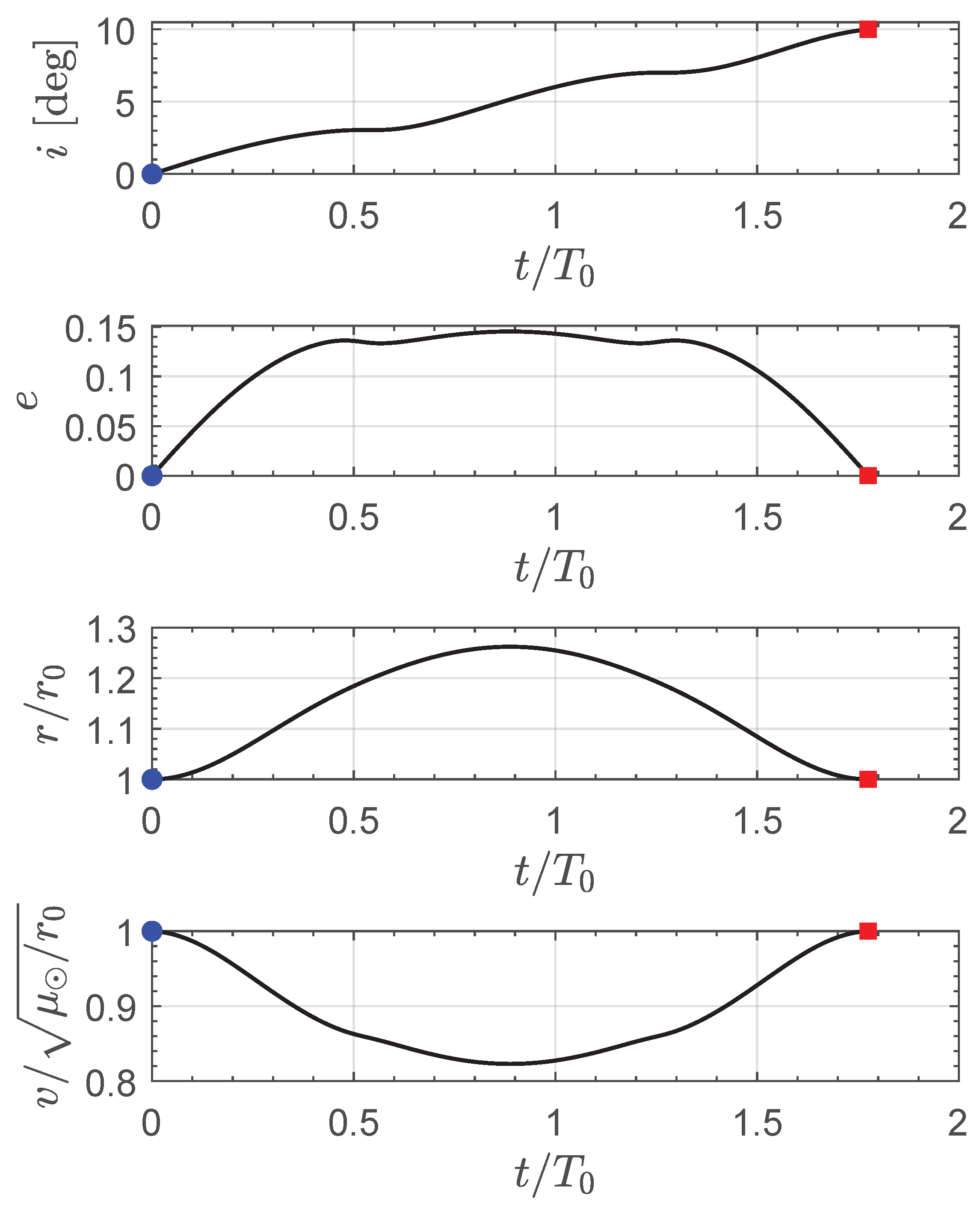
2. Spacecraft Orbital Dynamics
In this section, we consider a mission scenario in which an interplanetary spacecraft, equipped with an E-sail with assigned propulsive characteristics, covers a circular parking orbit of a given radius
around the Sun. Without loss of generality, we assume that the circular parking orbit is in the ecliptic plane, while the mathematical results discussed later in this section apply to a generic (initial) inclined circular orbit. In this heliocentric context, the spacecraft orbital dynamics are described in terms of modified equinoctial orbital elements
introduced by Walker et al. [
13,
14] in the mid-1980s. The modified equinoctial orbital elements have already been used by the author in several mission applications involving a solar sail-based spacecraft [
15]. For the sake of completeness, the passage between the modified equinoctial orbital elements and the classical orbital ones
, together with the calculation of the spacecraft heliocentric position (
) and velocity (
) vectors as a function of
, are detailed in
Appendix A. In particular, the equations summarized in
Appendix A are useful for calculating both the spacecraft boundary conditions (i.e., the non-singular elements at the beginning and at the end of the transfer) and the transversality condition [
16] described in the next section.
According to Refs. [
13,
14], all the modified equinoctial orbital elements are dimensionless, with the exception of
p, which coincides with the classical semilatus rectum of the spacecraft osculating orbit. In order to study the spacecraft dynamics in a more convenient form, we now introduce a dimensionless time
and a dimensionless (spacecraft) state vector
defined as
where
t is the (dimensional) time,
is the dimensionless version of the spacecraft osculating orbit semilatus rectum, and
is the Sun’s gravitational parameter. Therefore, the Sun–spacecraft distance
r can be written in a dimensionless form as a function of the modified equinoctial orbital elements as [
13,
14]
The above equation can be used to express the propulsive acceleration vector
induced by the E-sail propulsion system. In this respect, using the geometrical approach proposed by Huo et al. [
17] and assuming that the radius of the parking orbit is sufficiently close to 1 astronomical unit [
18,
19,
20], one has the following compact expression of vector
:
where
is the Sun–spacecraft unit vector,
is the unit vector normal to the shadowed sail nominal plane (defined as the plane that nominally contains the E-sail conducting tethers),
is a dimensionless term that models the thruster on/off condition obtained by switching the electron gun state, and
is the maximum value (reached if
) of the propulsive acceleration magnitude when the Sun–spacecraft distance is equal to
. In particular, the term
can be considered a sort of design parameter that defines the propulsive performance of the propulsion system. The value of
, in fact, depends on both the spacecraft mass breakdown (including the value of the payload mass) and E-sail characteristics such as the total tether length and the electric voltage [
21]. Bearing in mind the expression of
given by Equation (
2) and introducing the dimensionless propulsive acceleration vector defined as
one obtains the following equation, which gives the vector
as a function of the modified equinoctial orbital elements
, the switching parameter
, and the unit vectors
, viz.
where
is the dimensionless version of
, which coincides with the ratio between
and the Sun’s gravitational acceleration magnitude along the circular parking orbit.
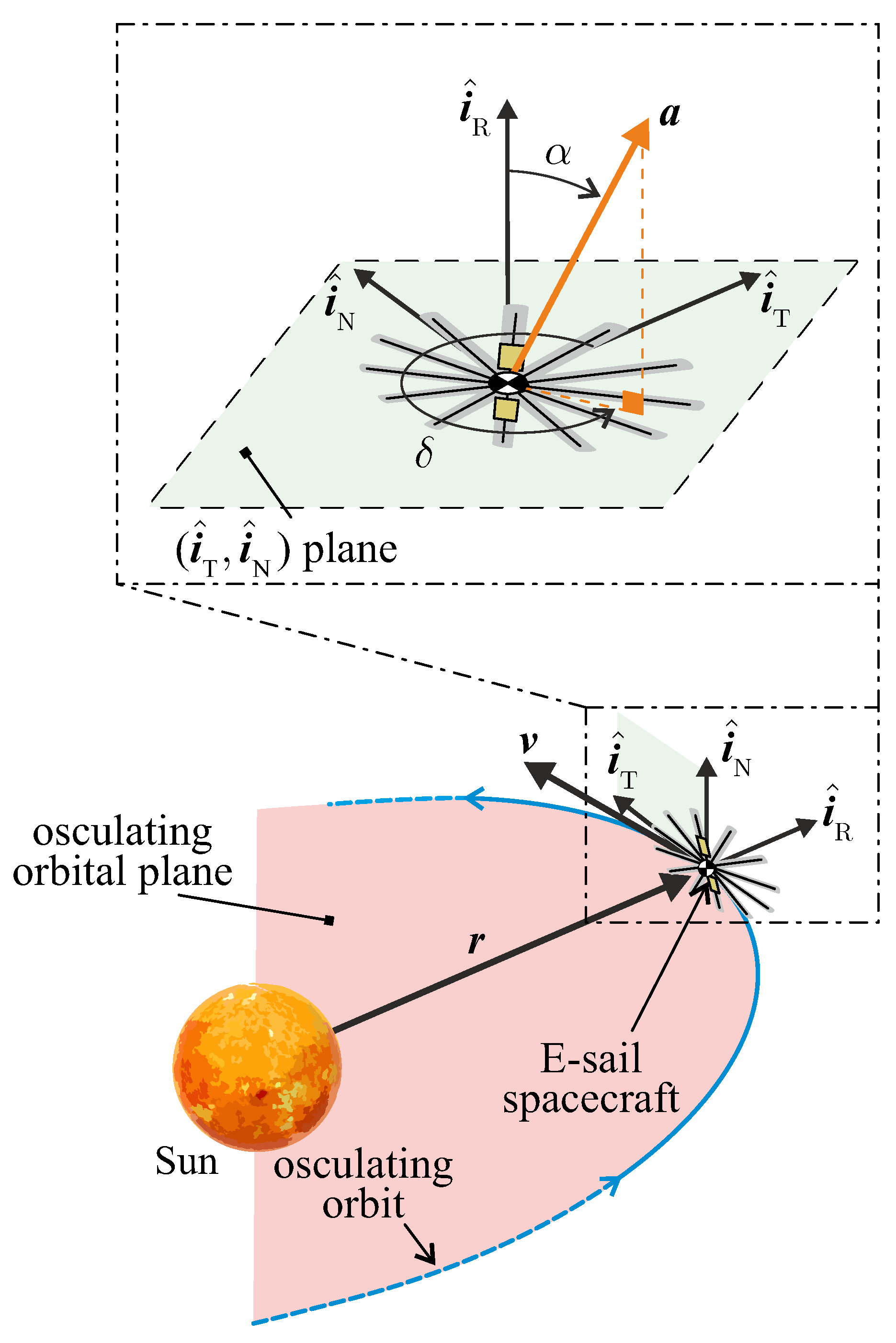
The expression of the dimensionless propulsive acceleration is then evaluated in a classical radial–transverse–normal (RTN) reference frame, whose unit vectors are
. In particular, the radial unit vector is defined as
, and the normal unit vector is perpendicular to the osculating orbit plane and is defined as
, while the transverse unit vector completes the right-handed frame, as sketched in
Figure 1.
In this figure, the two typical E-sail thrust angles of a three-dimensional scenario are indicated, that is, the cone angle
and the clock angle
. The latter is measured counterclockwise from the transverse direction (i.e., the direction of the unit vector
) into the
plane, while the range of
indicates that the E-sail-induced thrust vector cannot point toward the Sun, that is,
. In particular, the maximum value of the local propulsive acceleration magnitude is reached when
, that is, in a Sun-facing configuration [
22], when the sail nominal plane is perpendicular to the Sun–spacecraft direction.
According to the simplified scheme sketched in
Figure 1, and bearing in mind the thrust model described by Equations (
3) and (
4), it is possible to obtain the following expressions of the radial (
), transverse (
), and normal (
) components of the dimensionless propulsive acceleration vector
:
The three components of the vector
in the RTN reference frame are used to model the spacecraft heliocentric dynamics in terms of modified orbital equinoctial elements. In this respect, we adapt the approach proposed in Ref. [
23] for the analysis of an electric thruster-propelled trajectory, that is, a case in which the thrust vector is freely steerable and the spacecraft mass varies during the flight. In this specific case, however, the spacecraft mass is a constant of motion, and the direction of the (dimensionless) propulsive acceleration vector is modeled by Equation (
5), so the spacecraft heliocentric dynamics are described by the following dimensionless first-order differential equation:
where
are given by Equations (6)–(8), while the non-zero (dimensionless) entries of the matrix at the first term of the right side are defined as
Note that Equation (
9) can be rewritten in a compact form as
which will be used in the next section to analyze the optimal control laws in terms of the time variation in the three scalar control variables described later in this section. The initial conditions of the differential Equation (
9) are obtained by recalling that the parking orbit is circular and, by assumption, has a zero inclination with respect to the ecliptic plane. In this case, according to the equations summarized in
Appendix A, Equation (
9) (or, equivalently, Equation (
20)) is completed by the six scalar conditions at the dimensionless time instant
:
In particular, the condition indicates that, without loss of generality, the spacecraft true longitude L is zero at the beginning of the transfer. The latter is a rather general condition, because the parking orbit is circular, and the value of the longitude of the ascending node of the target (circular) orbit is left free.
The differential equations of motion (
9) can be numerically integrated with a typical PECE solver [
24,
25,
26] with a relative and absolute tolerance of
after the (dimensionless) time variation in the three scalar control parameters (that is, the cone and clock angles
and the switching function
) is determined in order to obtain the desired orbit transfer. In this respect, the mission scenario studied in this paper is the transfer from a circular ecliptic orbit to a circular inclined orbit whose characteristics are (1) a radius equal to
(i.e., the same value as the parking one) and (2) an inclination equal to
. In fact, recall that the inclination of the parking orbit is zero, so
coincides with the variation in orbital inclination obtained at the end of the flight, i.e., at the final time instant
. The value of the desired
is a mission parameter and is considered an assigned term in the trajectory design. The design of the time variation of the dimensionless control parameters
, which appear in the propulsive acceleration components given by Equations (6)–(8), is obtained in the optimization framework described in the following section.
3. Optimal Three-Dimensional Guidance Law
The time variation in the three dimensionless control parameters
has been calculated by minimizing the flight time
required to complete the three-dimensional circular orbit cranking for an assigned value of the dimensionless (reference) propulsive acceleration
and the inclination change
. Note, in fact, that the dimensionless version of the spacecraft dynamics given by Equations (
20) and (
21) does not depend on the specific value of the parking orbit radius
. The spacecraft trajectory optimization problem is solved using an indirect approach [
6,
27,
28], which allows the optimal control laws to be obtained, in an implicit form, as a function of the classical costate variables
[
29]. Note that, in this case, the costate variables are dimensionless, like the components of the spacecraft state vector
defined in Equation (
1).
The procedure used to set up the optimization problem with an indirect approach has been described in several authors’ works (see, for example, the papers collected in the recent special issue entitled “Advances in CubeSat Sails and Tethers” [
30], which cover some interesting mission scenarios involving both E-sail- and plasma-brake-propelled [
31,
32] spacecraft), so in this section, the focus is on the analytical form of the optimal control law. In particular, this section shows how the closed form of the optimal control law can be obtained as a function of modified equinoctial orbital elements and costate variables in a general three-dimensional orbit-to-orbit heliocentric mission scenario, such as that analyzed in this work. In this sense, the mathematical model proposed in this section is general (i.e., it is not constrained only to this specific mission application), and it is a useful contribution for the preliminary mission design of an E-sail-based spacecraft because, different from the solar sail case [
15], the evaluation of the local (optimal) value of the thrust angles does not require the maximization of a scalar function through a numerical method. Accordingly, the use of an analytical form of the optimal control law, which will now be described, allows the computation time of the numerical simulations to be substantially reduced with respect to the trajectory optimization of a solar sail-based heliocentric transfer mission.
From the mathematical point of view, using an indirect approach based on the classical calculus of variations, the analysis of the optimal control law in terms of the optimal variation in the three scalar control variables
begins with the study of the Hamiltonian function
, which, in this case, is defined as
where the explicit expression of the time derivative
is given by Equation (
20), while
is the adjoint vector whose components are the six adjoint variables, viz.
Equation (
22) is used, as usual [
33], to obtain the expressions of the six scalar Euler–Lagrange equations as
while the study of the optimal control law becomes simpler if only the part
of the Hamiltonian function that explicitly depends on the controls is considered. To this end, the expressions of the three components of the dimensionless propulsive acceleration vector given by Equations (6)–(8) are substituted into the right side of Equation (
20) so that, bearing in mind Equation (
22), the following expression of
is obtained:
The previous equation is used, according to Pontryagin’s maximum principle [
34,
35,
36], to obtain the optimal value (denoted by the superscript star) of the three scalar controls
at a generic dimensionless time instant
.
Assuming that the E-sail is switched on (i.e., assuming that
), the first control parameter, which is derived from Equation (
25), is the clock angle
. In this case, the necessary condition
gives the (optimal) value of the clock angle that maximizes the Hamiltonian function (i.e., maximizes the reduced Hamiltonian
), and the result is
Now, using the expressions of
and
given by Equations (
27) and (28) and again enforcing the necessary condition
the optimal value of the sail cone angle
can be obtained in a closed form as
In particular, the previous equation is the extension to the three-dimensional case, in which the modified equinoctial orbital elements are used to describe the spacecraft dynamics, of the result obtained in Ref. [
17] by using a geometrical approach.
Once the optimal values of the two thrust angles
have been determined through Equations (
27), (28), and (
30), the last scalar control can be derived from Equation (
25) by observing that the reduced form of the Hamiltonian function
is linear in the dimensionless on/off parameter
. In this context, neglecting the case in which singular arcs [
16] appear in the optimal transfer trajectory, a simple expression of the optimal value of the (binary) control parameter can be obtained by defining (see also Equation (
25)) a switching function SW as
where
and
are the optimal thrust angles previously obtained, so the optimal value
is given by
where
is the signum function.
To summarize, the optimal values of the three control parameters
are given by Equations (
27), (28), (
30), and (
32). These expressions are used in an automatic routine that numerically solves the two-point boundary value problem associated with the optimization process, with a tolerance of
. In this context, the seven scalar boundary constraints (recall that the flight time
is an output of the optimization procedure) required to complete the boundary value problem are obtained from the final conditions related to the circular target orbit and from the classical transversality condition [
16]. In particular, the four scalar conditions at the final time
, which are obtained through the analysis of the geometry of the circular inclined target orbit, are
while the transversality condition [
16] gives the remaining three scalar (final) constraints
In particular, the first condition in the latter equation indicates that the value of the true longitude at the end of the transfer is left free; that is, the optimization process models a typical orbit-to-orbit transfer between two assigned Keplerian heliocentric orbits. The next section illustrates the application of the mathematical model to an orbit cranking maneuver obtained using a medium-low-performance E-sail-propelled spacecraft.
4. Minimum-Time Orbit Cranking Numerical Simulations
Consider the example case in which the dimensionless reference propulsive acceleration is
, that is, the potential mission scenario in which the maximum propulsive acceleration magnitude (
) is equal to one-tenth of the Sun’s gravitational acceleration (
) along the circular parking orbit of radius
. For instance, when the reference radius is
, i.e., when the spacecraft parking trajectory approximates the Earth’s heliocentric orbit, the value
corresponds to a maximum propulsive acceleration magnitude of roughly
, because in that case, the Sun’s local gravitational acceleration is
. This value of propulsive acceleration magnitude is consistent with a typical multi-tether E-sail of medium-low performance [
21], while the single-tether configuration deployed by a three-unit (3U) CubeSat, which hopefully will be used to obtain the first flight validation of that propulsion system [
37,
38], is characterized by a much lower value of propulsive performance. In a first-generation single-tether E-sail [
37], in fact, the value of
when
will be roughly
.
Using a reference value of
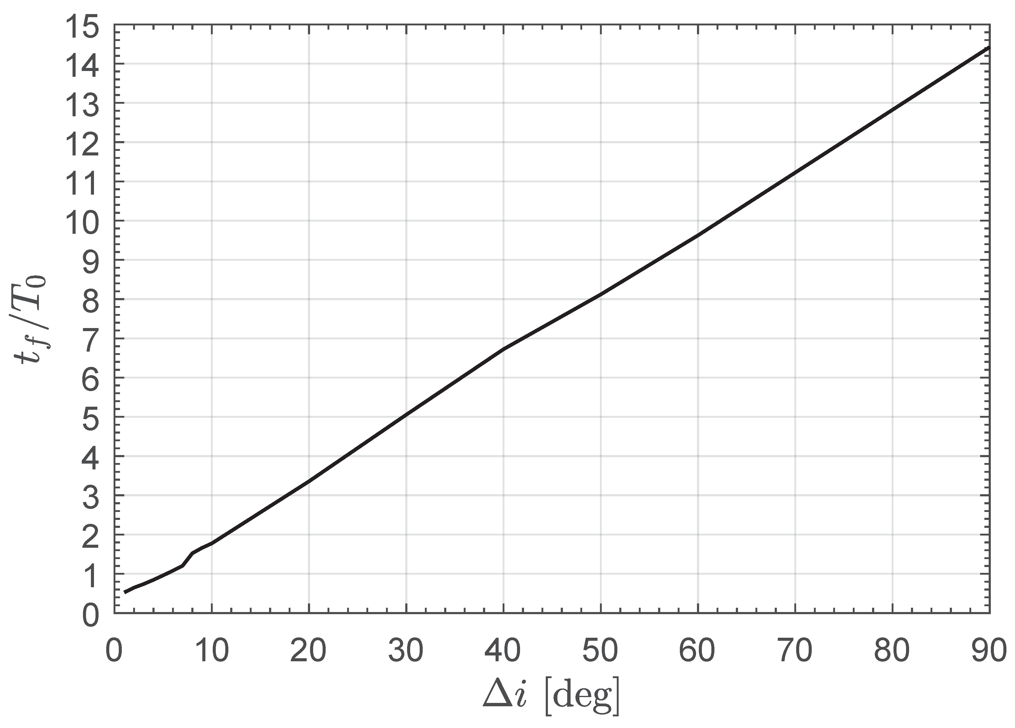
, the solution of the optimization problem described in the previous section gives the graph sketched in
Figure 2, which shows the minimum flight time
as a function of the change in orbital inclination
. In particular, the figure reports the ratio between
and the orbital period
of the circular parking orbit. Note that, according to the definition of the dimensionless time
given by Equation (
1), one has
, so the minimum value of
can be derived from
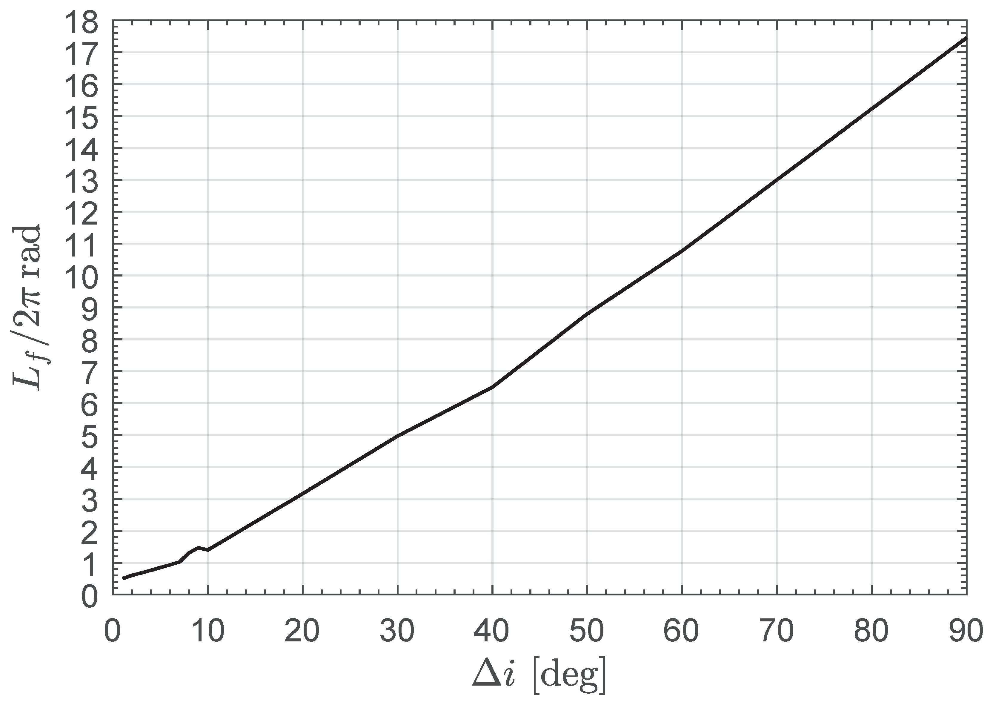
Figure 2 by suitably changing the scale of the ordinate axis. The numerical simulations also provide the data summarized in
Figure 3, which shows the value of the spacecraft final true longitude
obtained as an output of the optimization process. Note that the value of
is useful for obtaining a rapid indication of the number of complete revolutions around the Sun during the optimal spacecraft transfer.
In particular, as clearly indicated by
Figure 2, the variation in the minimum flight time with the change in orbital inclination is substantially linear when
. In this regard, a simple approximation of the dimensionless version of the function
can be obtained by using a typical best-fit procedure, and the result is
where
is in degrees.
For example, according to
Figure 2, an E-sail-based spacecraft with
is able to complete a cranking maneuver of
with a flight time of roughly
, while the approximate Equation (
35) gives a value
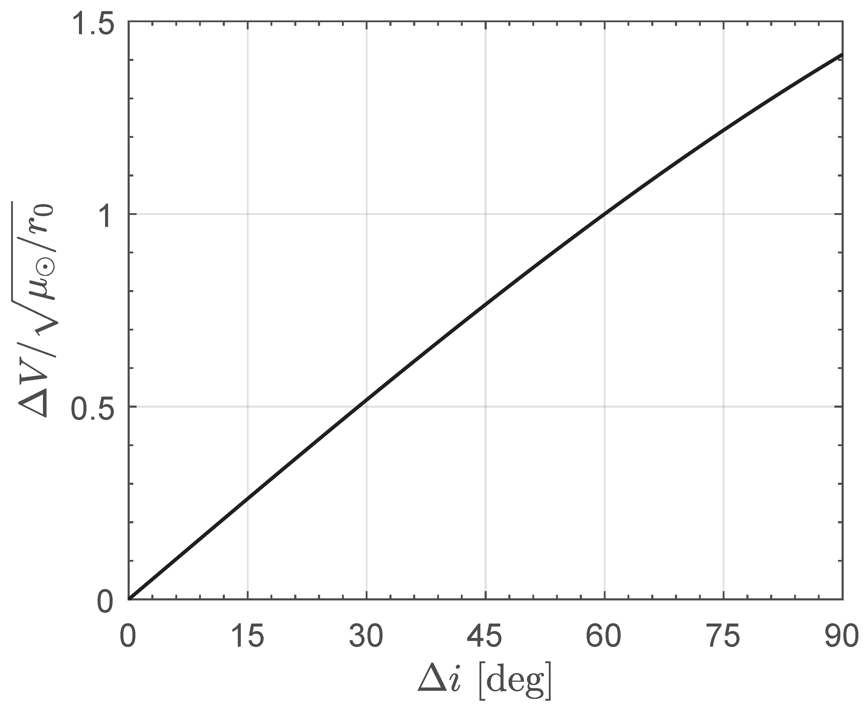
. This is an interesting result, because the same mission scenario would require a velocity change equal to
if orbit cranking is performed through a single impulsive maneuver; see the curve in
Figure 4, which has been obtained using the results discussed in Ref. [
1].
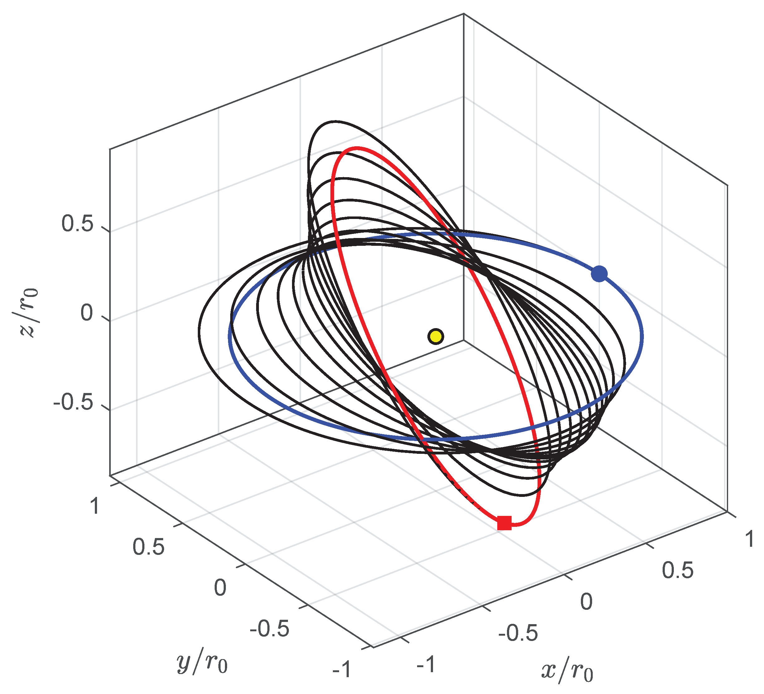
In an E-sail-propelled transfer, the optimal cranking maneuver requires slightly less than 11 revolutions around the Sun, as indicated by the graph in
Figure 3. This aspect is confirmed by
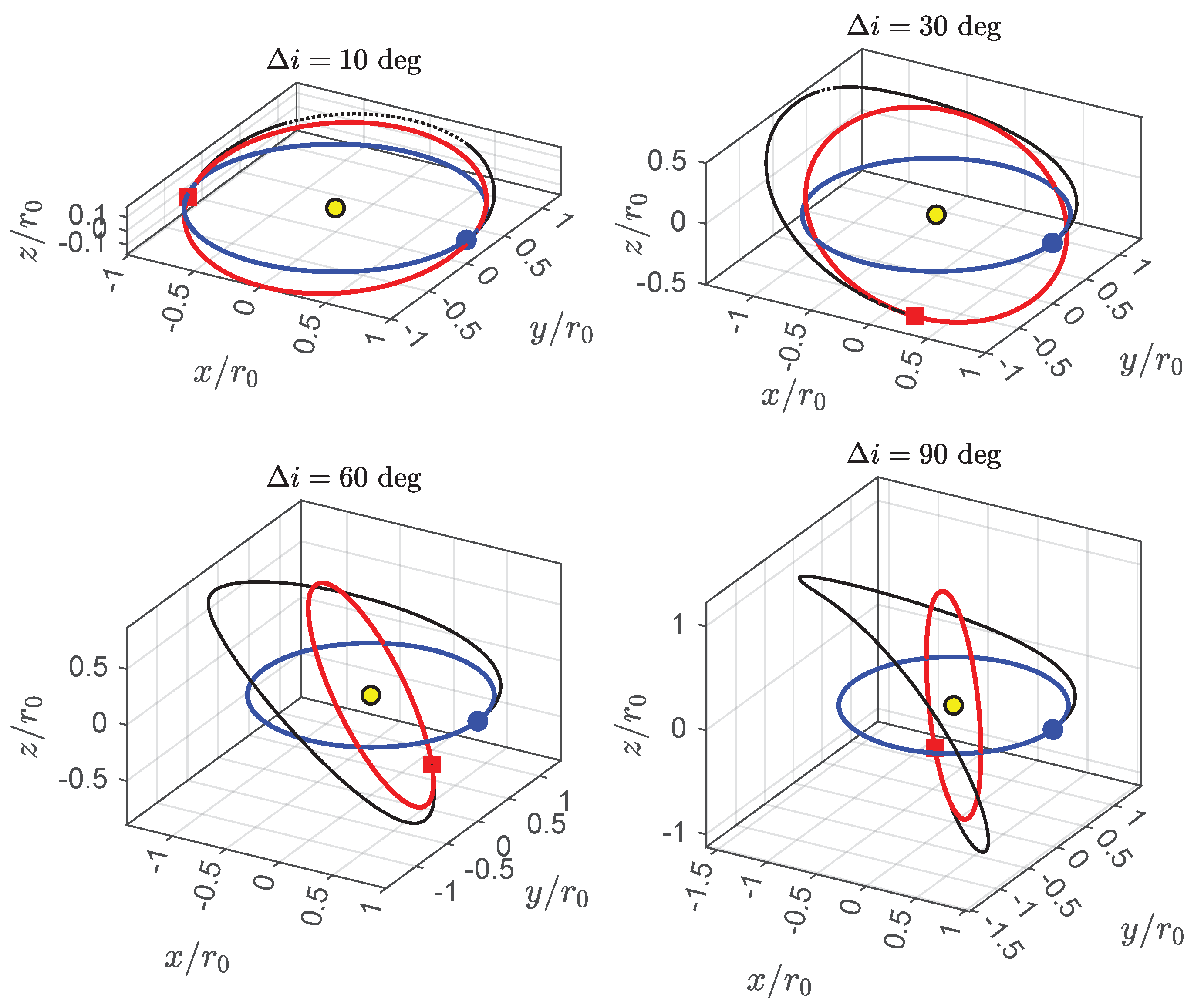
Figure 5, which shows the spacecraft optimal transfer trajectory in the heliocentric ecliptic Cartesian reference frame.
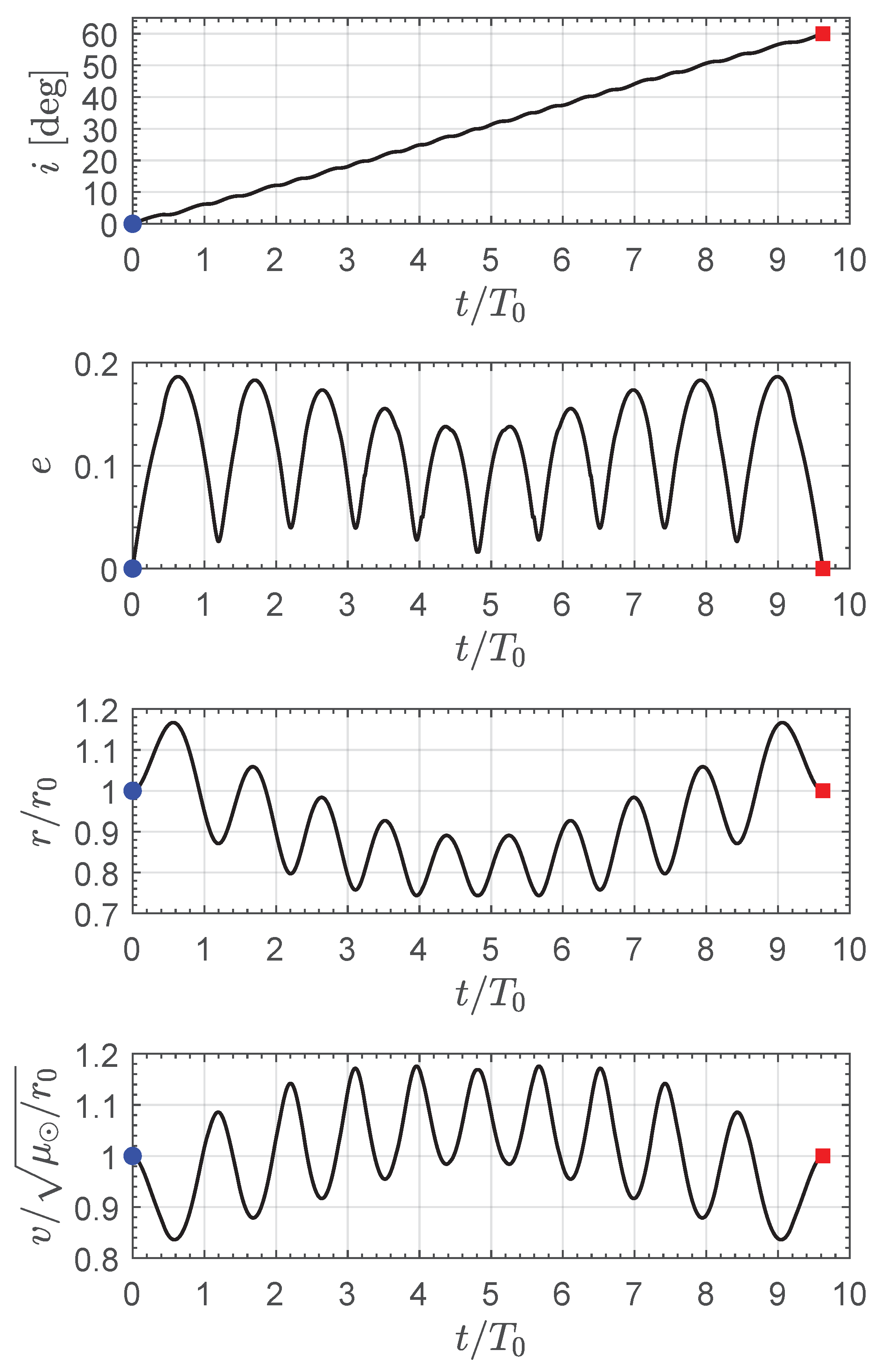
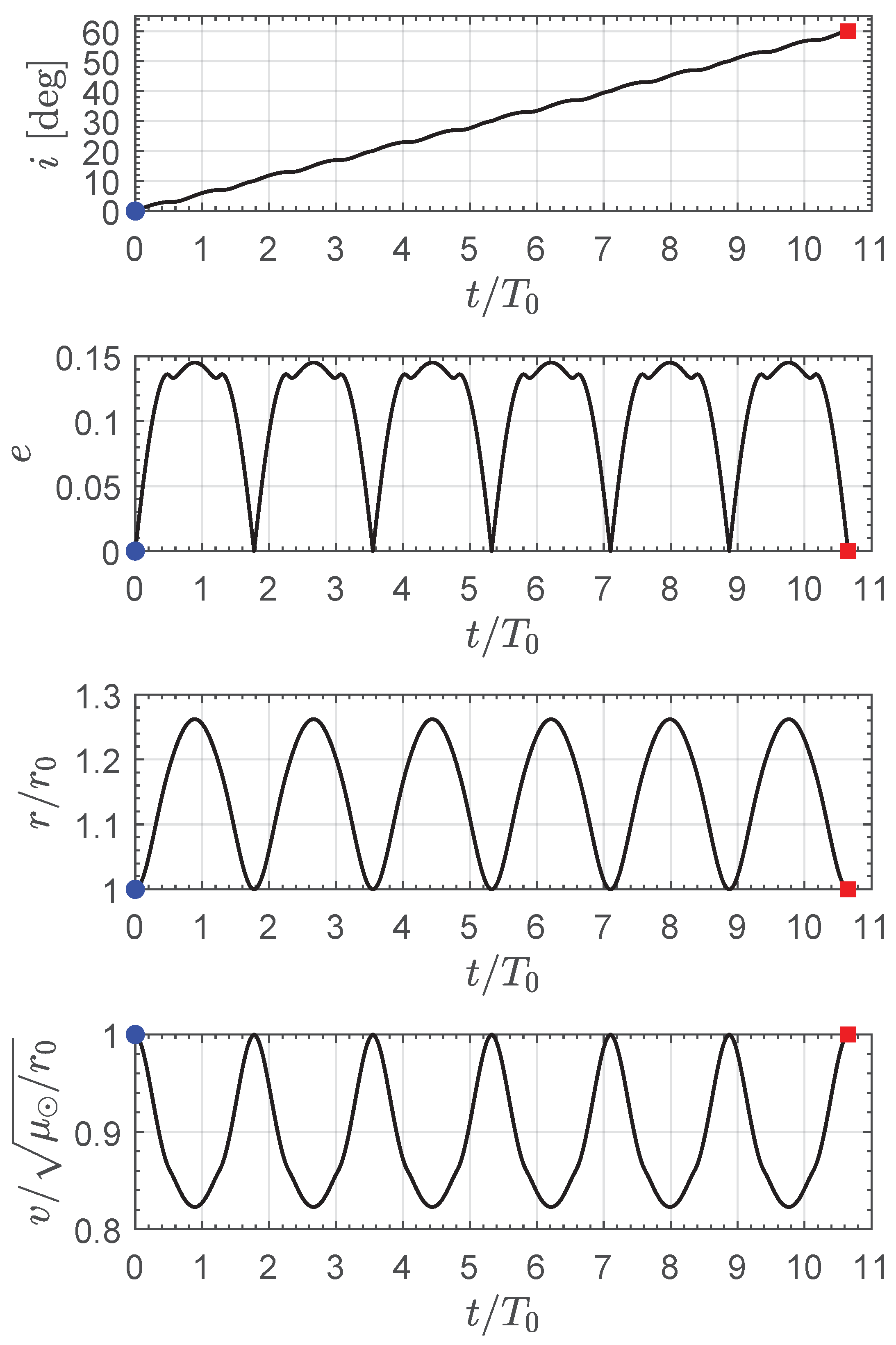
In this specific mission scenario, the time variation in the osculating orbit inclination (
i), the osculating orbit eccentricity (
e), the dimensionless solar distance (
), and the dimensionless magnitude of the spacecraft inertial velocity vector (
, where
) is sketched in
Figure 6.
In particular,
Figure 6 indicates that the variation in orbital inclination is substantially linear over time, while the osculating orbit eccentricity, the solar distance, and the magnitude of the velocity has an interesting symmetric behavior. In this regard, the graphs in
Figure 6 highlight that both the distance of the spacecraft from the Sun and its velocity magnitude remain close to the values that characterize the circular parking orbit. Finally,
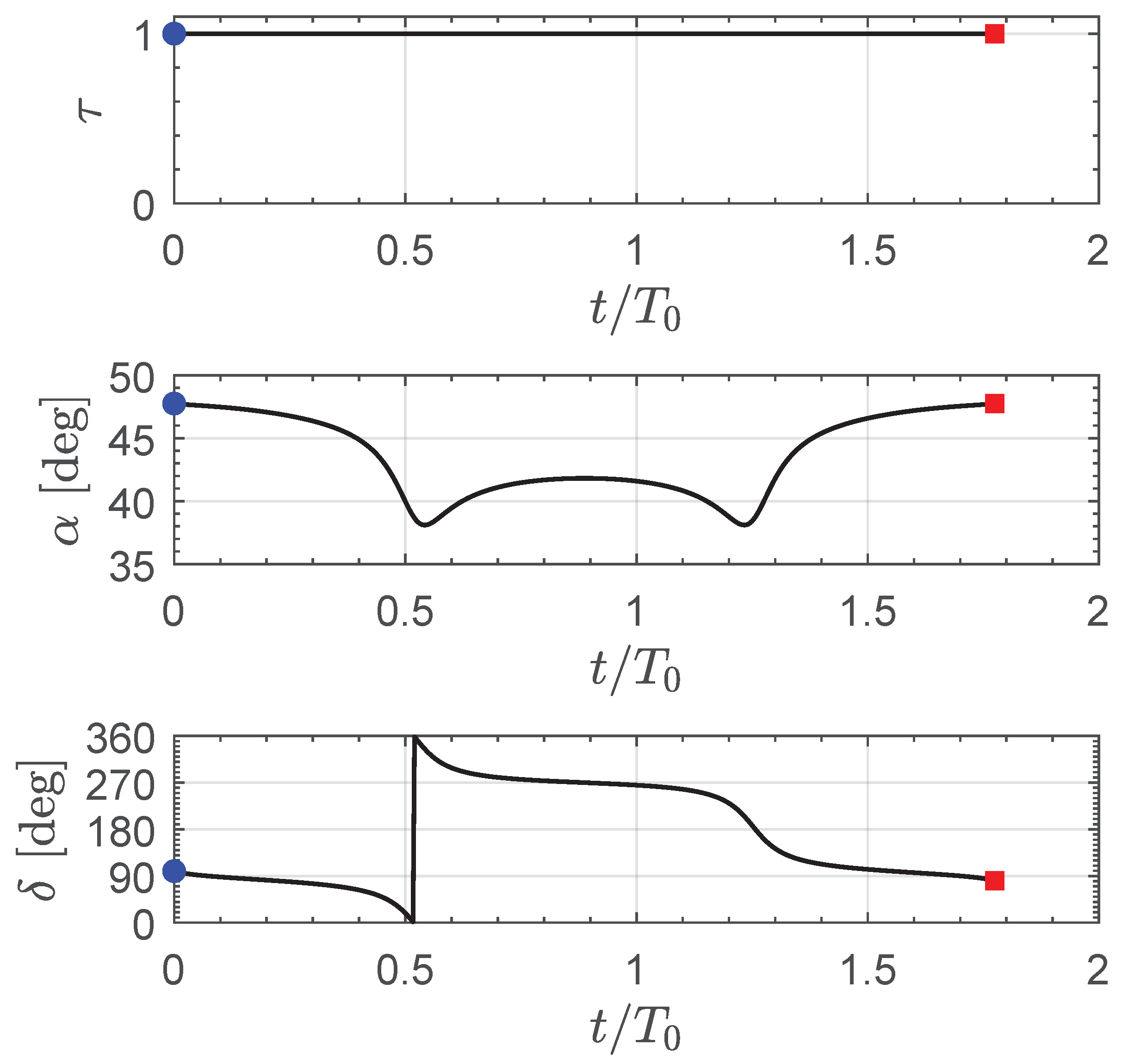
Figure 7 shows the time variation in the three scalar control parameters
, which substantially confirms the symmetry highlighted in the graphs in
Figure 6. Note that the E-sail propulsion system is switched on during almost the entire transfer, while the sail cone angle
has a mean value of roughly
, which is the value that maximizes the transverse component of the propulsive acceleration vector [
17,
39].
Figure 6 also indicates that the time history of the two thrust vector (control) angles
is rather complex during a transfer in which a large variation in orbital inclination is required. The next section discusses a different approach to obtain a near-optimal orbit cranking with a simplified control law, which can be employed when the value of
is sufficiently high.
5. Conclusions
This paper has analyzed the transfer trajectory of a spacecraft equipped with an Electric Solar Wind Sail in a heliocentric mission scenario in which the (orbital) inclination of the parking orbit is changed without varying its semimajor axis, that is, in a scenario where the parking and the target circular orbits share the same value of the radius. The transfer performance has been evaluated in an optimization framework by minimizing the flight time required to obtain an assigned value of the variation in orbital inclination for a given (reference) Electric Solar Wind Sail propulsive acceleration. Through a suitable selection of the distance and time units, the proposed mathematical model and the corresponding numerical results given by the solution of the optimization process are general, in the sense that they apply to a generic value of the circular parking orbit radius. In this context, the paper presents an analytical form of the optimal control laws obtained by using the well-known Pontryagin’s maximum principle, when the spacecraft dynamics are described through a set of modified equinoctial orbital elements, and the optimization problem is solved by using a classical indirect approach.
The numerical simulations presented in this paper refer to a medium-low-performance Electric Solar Wind Sail, while the proposed procedure can be easily extended to medium-high (or very high)-performance propulsion system, as detailed in
Appendix B, where an interesting topology of the optimal transfer trajectory (which resembles the transfer strategy adopted in the classical bi-elliptic transfer with a plane change) is illustrated and analyzed in detail. This paper also proposes an approximate procedure to rapidly obtain the optimal (i.e., the minimum-time) transfer performance of an Electric Solar Wind Sail with a low characteristic acceleration. In this respect, the approximate procedure allows the simplification of the time variation in the optimal control law when the value of the required variation in orbital inclination is high.
The analysis conducted in this paper confirms that the cranking maneuver of a circular heliocentric orbit is an interesting mission application of a propellantless propulsion system such as the Electric Solar Wind Sail. In fact, the mathematical model and the numerical results illustrated in the previous sections extend the literature regarding this challenging orbital maneuver, which substantially refers to a solar sail-based spacecraft, to a case where the primary propulsion system is that proposed by Dr. Janhunen in 2004. In this context, the numerical simulations indicate that an Electric Solar Wind Sail with a maximum propulsive acceleration magnitude, which is equal to one-tenth of the Sun’s gravitational acceleration along the circular parking orbit, is able to obtain an orbital inclination change of sixty degrees in slightly less than ten orbital periods of the starting heliocentric trajectory. Note that the same orbit cranking mission requires a velocity change equal to the spacecraft velocity magnitude along the (circular) parking orbit when a classical single-impulse maneuver is considered. This result indicates that the Electric Solar Wind Sail is an interesting option in such challenging mission scenarios.
Although the trajectory design approach discussed in this paper can be used for a generic value of the orbital inclination change, a possible simplification of the mathematical model can be obtained by considering a sufficiently small inclination variation. In that case, in fact, a sort of linearized approach can be employed to analyze the spacecraft dynamics by observing that the solar distance remains substantially constant during the orbit transfer. This scenario can be considered a potential extension of the mission application discussed in this work. In that context, the evaluation of the optimal performance when the parking orbit has an eccentricity different from zero is another interesting extension of the model proposed in this paper.

