Article

An Intelligent Control and a Model Predictive Control for a Single Landing Gear Equipped with a Magnetorheological Damper

1
Department of Mechanical Engineering, Incheon National University, Incheon 22012, Republic of Korea
2
Faculty of Mechanical Technology, Ho Chi Minh City University of Industry and Trade, 140 Le Trong Tan Street, Tay Thanh Ward, Tan Phu District, Ho Chi Minh City 700000, Vietnam
3
School of Aerospace and Mechanical Engineering, Korea Aerospace University, Goyang-si, Gyeonggi-do 10540, Republic of Korea
*
Authors to whom correspondence should be addressed.
These authors contributed equally to this work.
Aerospace 2023, 10(11), 951; https://doi.org/10.3390/aerospace10110951
Submission received: 14 October 2023 / Revised: 6 November 2023 / Accepted: 9 November 2023 / Published: 11 November 2023

Abstract

:
Aircraft landing gear equipped with a magnetorheological (MR) damper is a semi-active system that contains nonlinear behavior, disturbances, uncertainties, and delay times that can have a huge impact on the landing’s performance. To solve this problem, this paper adopts two types of controllers, which are an intelligent controller and a model predictive controller, for a landing gear equipped with an MR damper to improve the landing gear performance considering response time in different landing cases. A model predictive controller is built based on the mathematical model of the landing gear system. An intelligent controller based on a neural network is designed and trained using a greedy bandit algorithm to improve the shock absorber efficiency at different aircraft masses and sink speeds. In this MR damper, the response time is assumed to be constant at 20 ms, which is similar to the response time of the commercial MR damper. To verify the efficiency of the proposed controllers, numerical simulations compared with a passive damper and a skyhook controller in different landing cases are executed. The major finding indicates that the suggested controller performs better in various landing scenarios than other controllers in terms of shock absorber effectiveness and adaptability.

1. Introduction

Magnetorheological (MR) dampers are generally used in many applications, such as architectural structures [1], car suspensions [2], and home applications [3,4]. Yet, applications in the aerospace domain are not common [5,6]. The advantage of the MR damper is that it has a simple structure by basically revising from the passive damper, and it is continuously controllable due to containing MR fluid [7]. However, three main challenges prevent MR dampers from being widely used in the aerospace industry, in particular landing gear applications. First, an MR damper is a complex nonlinear system. It always exhibits nonlinear hysteresis between its output force and relative velocity and nonlinear stiffness due to the state transition from liquid to semi-solid [8]. Second, the MR damper contains an unavoidable time delay [9] or response time [10]. The response time of the damper was identified in the range of 15–55 ms [11,12], which is not too short compared to the duration of the touchdown phase, which is about 50–200 ms. Thus, the response time may have a huge impact on the landing gear performance. Third, the aircraft must land in different landing cases, such as variable aircraft mass and sink speeds.
In an attempt to solve these problems, many researchers have successfully developed many controllers so far. For example, Yue Zhu and Sihong Zhu [13] developed a quarter-vehicle suspension equipped with an MR damper with a time delay using an adaptive neural network structure. Laihua Tao et al. [14] applied a Smith predictor-Taylor series-based LQG control to compensate for the time delay of a vehicle’s semi-active suspension. Young-Tai Choi et al. analyzed MR dampers [15] and developed the controller for the landing gear system of a helicopter equipped with MR dampers. Yoon et al. [16] produced the force control based on the foundation of the optimal damping force. Jo et al. [17] applied two semi-active control algorithms, which are the skyhook control and hybrid control, to control the MR damper landing gear under various landing conditions. Knap et al. [18] developed a construction of a vehicle vibration damper controlled using a piezoelectric actuator that has a very small delay time of about 10 ms. So far, the control algorithm for landing gear in differing landing cases considering MR response time has not yet been invested. To deal with the MR response time, two types of controllers are the candidates: model predictive control (MPC) and intelligent controller based on reinforcement learning.
The advantage of MPC is that it computes a sequence of manipulated variable adjustments in order to optimize the future behavior of a plant [19]. An MPC algorithm computes a sequence of controlled variable adjustments for the future at each control interval in an effort to optimize plant behavior in the future. A solid introduction to the theoretical and practical challenges related to using MPC to deal with complex dynamic systems that contain time delays may be found in many recent papers. Mai et al. [20] presented the vibration control of a semi-active quarter-car suspension system equipped with a magneto-rheological damper that provides the physical constraint of a damping force. Dong et al. [21] introduced a gray skyhook prediction controller to compensate for the response time of magnetorheological semi-active seat suspension.
An intelligent controller based on reinforcement learning has been used to enable adaptive autonomy [22] and solve the optimization problem in autonomous control systems [23]. The concept of a full reinforcement learning algorithm, such as Q-learning and Sarsa, is that an agent improves its future action based on the long-term reward value of a pair of current states and actions [24]. The full reinforcement learning algorithm is developed based on the Markovian decision process, and it needs a big neural network to store all the reward values of all pairs of current state and action. A deep neural network is usually chosen in control systems [25]. A simple feedback reinforcement learning method is used as a bandit algorithm. This algorithm chooses the best action based on the history of all the past actions. So, the bandit algorithm can work well on the non-Markov chain system, and it requires a small neural network to link the state to the best action. Thus, the bandit algorithm is frequently encountered in various practical applications, such as recommender systems [26] and linear control systems [27].
The primary focus of this paper is to develop a simple controller that can improve the performance of a single landing gear equipped with an MR damper, which contains the response time in differing landing cases. In order to achieve this goal, a mathematical model of a landing gear system equipped with an MR damper is developed using MATLAB and then verified with the experimental data. Two types of controllers, a model predictive control and a simple bandit neural network controller, are then developed to compensate for the response time of the MR damper in differing landing cases.
The structure of the paper is arranged as follows: Section 2 shows the structure of a single landing gear equipped with the MR damper, and the mathematical model of our landing gear system is developed and verified; Section 3 explains the concept of the control design; Section 4 details the simulation results; and the conclusion is shown in Section 5.

2. Mathematical Model of the MR Damper

2.1. Structure of the Landing Gear Equipped with an MR Damper

In this paper, the structure of the landing gear is inspired by the work [17,28], as shown in Figure 1. The MR damper, which includes a piston, a cylinder, MR fluid, a floating piston, and a gas accumulator, is the main component of the landing gear. The head of the piston divides the MR fluid-MRF-140CG, which is entirely injected into the MR damper, into upper and lower hydraulic chambers. This fluid from one chamber must pass through the orifices to the other chamber due to the piston action when the landing gear makes contact with the ground. It causes friction forces to develop within the vital fluid as well as between the fluid and the piston. Thus, when the landing gear makes contact with the ground, the landing energy can be smoothly absorbed. To account for the volume of the head piston caused by the piston’s movement, pressurized air is built up inside the piston. Additionally, the compressed air serves as a spring, storing extra energy during the compression phase and releasing it during the ensuing extension period. The MR core, which houses the magnetic circuit, is inserted inside the piston’s head. The electrical cable that exits the damper through a hole on the top of the cylinder carries electrical current to the MR core from the external electric board. Two wheels are symmetrically arranged on the landing gear to lessen the effect of friction force between the bearings and the piston.

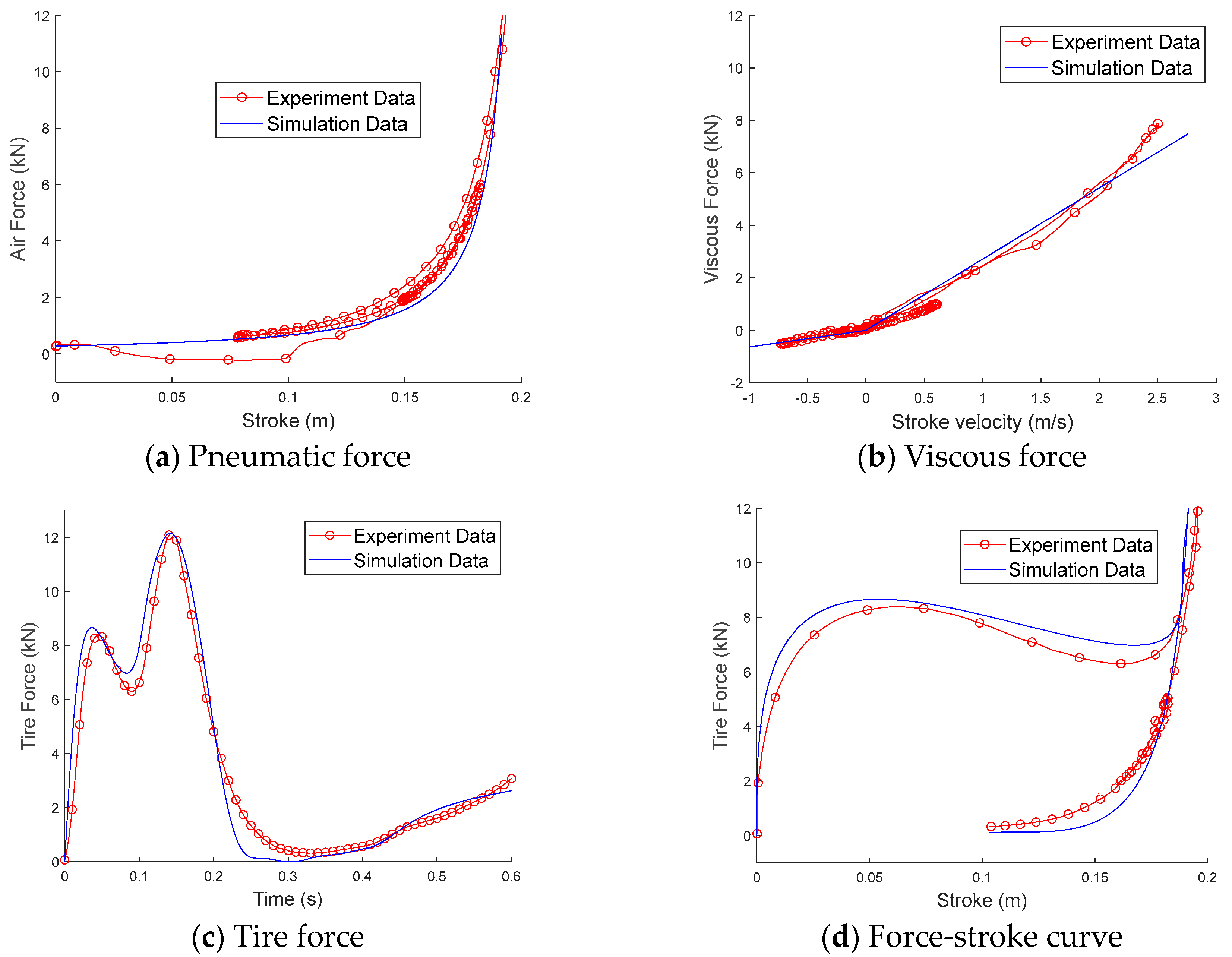
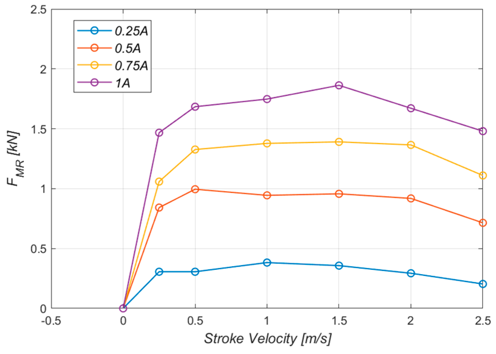
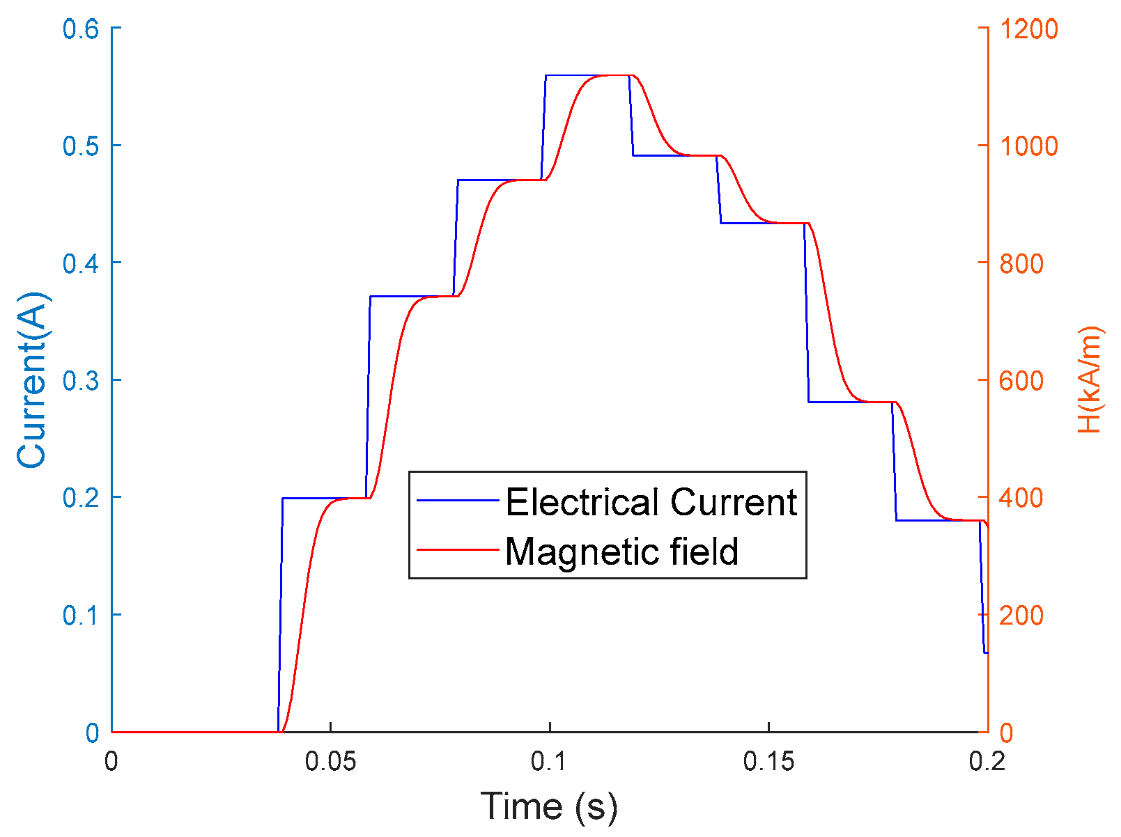
2.2. Mathematical Model

The straightforward model of the landing gear during touchdown is detailed in the work [29]. It can be assumed that the upper and lower bodies of the landing gear move independently during touchdown, as can be seen in Figure 2. Consequently, the dynamic landing gear system’s equations of motion are as follows [30]:
m 1 z ¨ 1 = m 1 g F a F v F M R
m 2 z ¨ 2 = m 2 g + F a + F v + F M R F T
z 1 t = 0 = z 2 t = 0 = 0 , z ˙ 1 t = 0 = z ˙ 2 t = 0 = v
where z1 and z2 are the displacements of the aircraft and the wheel, respectively. For a closed system, the polytropic gas law is determined by the pneumatic force Fa:
F a = A p p 0 V 0 V 0 A p s n
where s = z1− z2 is the stroke. The viscous force Fv represents the viscous-induced stress or the Newtonian behavior of fluid as follows:
F v = C s ˙
where C is the viscous co-efficiency. The tire force is the ground’s reaction force to the tire and it indicates tire deformation:
F T = k T z 2 b
All parameters are given based on the work [17], as can be seen in Table 1. In that work, the authors executed many drop test experiments to find the characteristics of the landing gear. The specifics of the landing gear drop test experiment are displayed in Figure 3. The load cell, laser sensor, position sensor, accelerometer, and two pressure sensors are the five sensors that make up the drop test system. A dSPACE small box connected to a host PC running MATLAB Simulink was used to obtain the data. To retrieve the excitation signals and supply the MR damper with electrical current, the Simulink block was created. The comparison results of the mathematical model and the drop test experiment of the landing gear under the conditions of m1 = 245 kg, and sink speed v = 3 m/s are given in Figure 4. It can be seen that there is a small error of under 5% between the results of the mathematical model and the experiments.
By adjusting the current supplied to the MR damper core from 0 A to 1 A at intervals of 0.25 A, the controlled force was determined. Figure 5 presents the findings. The control damping force increased with increasing electrical current; at 1 A of current, the maximum value of the MR force was observed at 1.7 kN.
The response time of the MR damper is defined as the required time to transition from the initial state of electrical current to 95% of the final state of the MR damper force [10]. The response time of an MR damper contains the response time of the magnetic circuit and the response time of the MR fluid [11]. The response time of MR fluid is very small, less than 1 ms, so it is assumed to be neglected. Thus, the main source of the response time of the MR damper is in the electrical circuit that generates the magnetic field from the input of the electrical current. It is difficult to determine the value of the response time due to the lack of equipment to measure the magnetic field. Thus, the response time of this research is about 20 ms, which is similar to the response time of the commercial MR damper [31]. The response time of the MR damper can be described using the sigmoid function:
s i g m o i d x = 1 e 2 x 1 + e 2 x
The simulation result of the response time of the MR damper with variable applied electrical currents using the sigmoid function is shown in Figure 6. In our research, other delays, such as sensor and processor calculation delays, are assumed to be small; hence, they are assumed to be neglected. The sampling time is also chosen at 20 ms.

3. Control Design

3.1. Control Target

Shock absorber efficiency is a metric unit to measure the percentage of the landing energy that is absorbed by a landing gear during the first stroke [32]. The shock absorber efficiency is calculated by the ratio between the total energy absorber of the landing gear during the first stroke and the product of maximum damping force ( F d m a x ) and maximum stroke ( s m a x ). Thus, the shock absorber efficiency can be calculated by the following:
η = 0 s m a x F d d s s m a x F d m a x
where damping force Fd = Fv + Fa+ FMR. During touchdown, the landing gear must absorb all the potential and kinetic energy of the aircraft, as can be seen in the following example:
F T d z 2 + F d d s = m 1 + m 2 g z 1 + 1 2 m 1 + m 2 v 2
In Equation (9), the right-hand side indicates the overall energy of the aircraft during touchdown, which is the kinetic and potential energy, while the left-hand side reflects the total energy that is absorbed by the landing gear system. Therefore, the aircraft mass and sink speed are the only two key variables that can alter this total energy. Moreover, the time delay is also the target of this research. So, the goal of the control is to improve the performance of the landing gear, which involves the time delay of the MR damper and various landing conditions. Or, the cost function of the control is to maximize the shock absorber efficiency in each of the landing cases in Table 2.
J = E η + w Δ η
where
E η = 1 9 i = 1 9 η i Δ η = 1 9 i = 1 9 η i E η
and w = −1 is the scalar value.

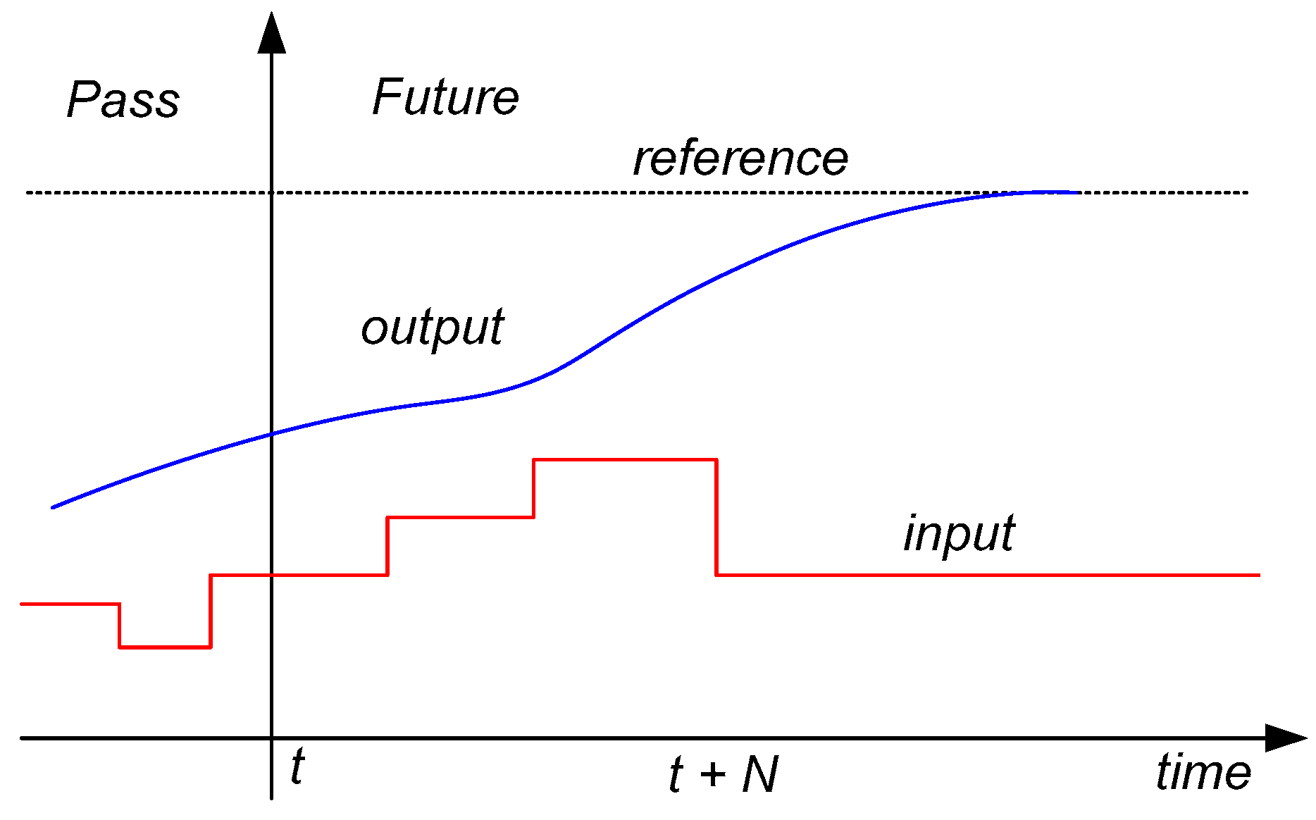
3.2. Model Predict Controller

MPC is a set of advanced control methods that explicitly use a model to predict the future behavior of the system [33]. The fundamental idea of MPC is illustrated in Figure 7. Based on the measurements made at time t, the controller forecasts the dynamic behavior of the system across a prediction horizon forward N steps in the future and chooses the input so that a specified open-loop performance objective is minimized (over a control horizon t + N). Normally, the target of MPC is to minimize the difference between the output of the system and the reference. In our proposed system, the main goal is to maximize the shock absorber efficiency, which is hard to achieve the goal of the MPC algorithm, as can be seen in Equation (10). So, the first step of the control design process is to find the approximate object function of the MPC.
From Equation (8), the aircraft landing gear achieves the maximum shock absorber efficiency when the numerator equals the denominator. So, the total energy of the aircraft during touchdown is seen to be rearranged into a rectangle that has a maximum constant damping force as its width. Thus, to improve the performance of the landing gear during touchdown, the idea of the control is to maintain the ideal maximum damping force (Ftarget) as long as possible during the first stroke, as can be seen in Figure 8 [30]. From Equation (9), under a landing condition (m1, v), the right-hand side is constant. Moreover, the tire absorbs a small amount of energy, so the total energy that is absorbed by the damper is constant under a landing condition whether the MR damper is used or not. Thus, the target damping force is calculated based on the performance of the passive damper:
F t a r g e t = F d . p a s s i v e d s s i d e a l
The numerator in Equation (12) represents the total energy of a passive damper. The total energy of the ideal control is the area of the rectangle that has a width of Ftarget and a length s i d e a l   0.9 s m a x . The values of Ftarget under various landing conditions are given in Figure 9.
The MPC is designed to drive the MR damper following the Ftarget, so the cost function of MPC can be given as follows:
C o s t   f u n c t i o n = E r   d t E r =     0 ,     F t a r g e t < F d F t a r g e t F d ,     F t a r g e t F d 0 u 1
In Equation (13), the semi-active condition has been applied. During the first stroke, the stroke velocity is always positive, so the MR damper cannot generate the negative following the semi-active condition. Thus, the MR damper turns off in case the damping force is less than the Ftarget.
The MPC algorithm is detailed in Figure 10. It can seem that at time t, after receiving the sensor signals, which are the potentiometer to measure stroke and the accelerometer to measure an aircraft’s acceleration, the MPC calculates N times forward the future control input based on the mathematical model, as
u M P C ( t ) = i = 0 N E r ( i )
where i is the calculation step. The compensation damping force at step i is calculated based on Equation (13):
E r i =     0 ,     F t a r g e t < F ^ d ( i ) F t a r g e t F ^ d ( i ) ,     F t a r g e t F ^ d ( i )
where the estimation of damping force at step i is calculated based on Equations (4) and (5):
F ^ d i = F a + F v + F M R ( i )
The initial MR force F M R i = 0 , and the MR force is calculated following Equation (16) at step i. Based on the mathematical model in Section 2.2, the future state of landing gear can be predicted following Equations (1)–(3). Assuming the control is calculated using a very strong computer that can solve the aircraft’s dynamic equation under 1 ms. Thus, the number of future steps N can be chosen by 20.

3.3. Bandit Neural Network Controller

An intelligent control based on the reinforcement neural network is the most famous control that can improve the system’s adaptive ability considering the unknown environment [34]. The concept of the intelligent controller involves two main parts, which are the structure of the neural network and the algorithm used to find the parameters in the neural network. The structure of the neural network is shown in Figure 11. As can be seen, there are only three inputs, which are stroke, stroke velocity, and aircraft acceleration, from two sensor signals. The output of the neural network is the electrical current, which is then applied to the MR damper. And there is only a hidden layer with ten neurals.
O u t p u t = f i n p u t × W + b i a s f x = 0 ,         x < 0 x ,         1 x 0 1 ,         1 > x
As mentioned before, the greedy bandit algorithm, which is a simple method in machine learning algorithms, is applied to find the optimal weight matrix and bias vector of the neural network. The concept of greedy bandit is shown below:
Initialization:
W m a x = 0 Q ( 0 ) = 0 k i = 0 P = 0.5
While looping until Q k i   0.9 or k i   200
W = W m a x       w i t h   p r o b a b i l i t y   1 P W m a x + 0.2 × r a n d 0   1     w i t h   p r o b a b i l i t y   P
  •    R ≤ bandit(W):
  •       If J ( W ) > J W m a x :
  •           W m a x = W
  •           R = 0
  •       else:
  •           R = 0.9
Q ( k i + 1 ) = ( k i ) + R Q k i ) ) / k i k i = k i + 1
The algorithm only considers the weight matrix Wmax, which has the maximum value of action Q( k i ). In the beginning, this weight matrix of the neural network is zero. The greedy algorithm is used to select exploiting or exploring actions. After exploiting actions, the agent will receive the maximum reward R = 0.9, which represents the maximum expected value of shock absorber efficiency. While exploring actions, the agent will be punished with R = 0 if the cost function J ( W ) of the current weight matrix is larger than the cost function of J W m a x . The value of action Q(ki) is then updated based on that reward, as can be seen in Equation (20). The algorithm converges when this value of action Q(ki) reaches the maximum reward. The numerical simulation result of the greedy bandit algorithm is shown in Figure 12. It can be seen that the algorithm converges after more than 100 loops. The maximum value of the cost function is nearly 90%.

4. Result and Discussion

To compare with the proposed controllers, the passive damper and skyhook controller are applied. The skyhook controller is the classical control that is used to control a suspension. The principle of skyhook control is given by the following:
u s k y =         C s k y z ˙ 1 ,     z ˙ 1 s ˙ > 0       s ˙ > 0 0 ,     e l s e w h e r e
where Csky is the skyhook gain that is turned depending on the landing condition, as can be seen in Figure 13. In order to use that controller efficiently, the aircraft mass and sink speed are assumed to be known before touchdown.
To verify the efficiency of the proposed controllers, many numerical simulations are executed using MATLAB. Figure 14 shows a comparison of the landing gear performance of the passive damper, skyhook controller, MPC, and intelligent controller in the case of a heavy landing. As can be seen, the sampling time is 20 ms, so during the first stroke of about 150 ms, there are only seven control loops that are executed. The passive damper shows the highest tire force that can attach to the frame of the aircraft. All controllers dramatically reduce the maximum damping force. The proposed controllers exhibit better landing performance than that of other controllers. It produces the smallest stroke value, the smallest absolute aircraft acceleration, and the highest shock absorber efficiency. The MPC controller only predicted 20 steps forward in the future, while the intelligent controller simulated the whole system and chose the best action to claim the best cost function. So, the intelligent controller performed better than the MPC did. However, MPC can be executed online, whereas the intelligent controller must be trained offline based on several trials and errors.
Table 3 details the comparison of the shock absorber efficiency of landing gear using the passive damper, skyhook controller, and the proposed controllers at different aircraft mass and sink speeds. As can be seen, the proposed controllers also exhibit higher shock absorber efficiency than other controllers at various aircraft mass and sink speeds. In both the MPC and skyhook control, the landing conditions are assumed to be known, while the intelligent controllers do not require any knowledge of landing conditions. In order to verify the generalization ability of the proposed controllers, numerical simulations in the three random landing cases are executed, which are out of data training. Overall, the intelligent controller produced better adaptive ability than other controllers.

5. Conclusions

This paper adopted two types of control, which are MPC and intelligent control, for a single landing gear equipped with an MR damper in differing landing cases, considering the response time of the MR damper. Both the MPC and the intelligent controller required an accurate mathematical model for their design. So, the mathematical model of the landing gear touchdown dynamic is built and verified by the results of the drop test experiment. The MPC was built based on this mathematical model to reduce the effect of the time delay. An intelligent control based on the neural network was developed and trained using a greedy bandit algorithm. To verify the efficiency of the proposed controllers, many numerical simulations with different controllers, which are passive damper and skyhook control, in different landing scenarios were executed. Compared with other controllers, the proposed controllers have exhibited better shock absorber efficiency and also improved the adaptive ability of the landing gear system in different landing cases. In future work, the drop test experiment will then be set up to verify the efficiency of the proposed controller in the real case. Also, the controller will be developed to improve the robustness of the MR damper in different landing cases.

Author Contributions

Data curation, H.-M.P., Q.-V.L., Q.-N.L. and H.-H.P.; Formal analysis, H.-M.P., Q.-V.L., Q.-N.L. and Y.K.; Investigation, Y.K. and H.-H.P.; Methodology, H.-H.P. and J.-H.H.; Project administration, Y.K., Q.-V.L. and J.-H.H.; Software, H.-M.P., Q.-V.L. and Q.-N.L.; Supervision, Y.K. and J.-H.H.; Writing—original draft, Q.-V.L.; Writing—review and editing, H.-M.P., Q.-N.L., Y.K., H.-H.P. and J.-H.H. All authors have read and agreed to the published version of the manuscript.

Funding

This work was supported by the Incheon National University Research Grant in 2019.

Data Availability Statement

Data sharing is not applicable to this article.

Acknowledgments

The authors are very grateful for the support received from the Ho Chi Minh City University of Industry and Trade, Incheon National University, and Korea Aerospace University for this research.

Conflicts of Interest

The authors declare no conflict of interest.

References

  1. Fallah, A.Y.; Taghikhany, T. Robust Semi-Active Control for Uncertain Structures and Smart Dampers. Smart Mater. Struct. 2014, 23, 095040. [Google Scholar] [CrossRef]
  2. Oh, J.-S.; Choi, S.-B. Ride Quality Control of a Full Vehicle Suspension System Featuring Magnetorheological Dampers with Multiple Orifice Holes. Front. Mater. 2019, 6, 8. [Google Scholar] [CrossRef]
  3. Chae, H.D.; Choi, S.-B. A New Vibration Isolation Bed Stage with Magnetorheological Dampers for Ambulance Vehicles. Smart Mater. Struct. 2015, 24, 017001. [Google Scholar] [CrossRef]
  4. Bui, Q.-D.; Nguyen, Q.H.; Nguyen, T.T.; Mai, D.-D. Development of a Magnetorheological Damper with Self-Powered Ability for Washing Machines. Appl. Sci. 2020, 10, 4099. [Google Scholar] [CrossRef]
  5. Choi, Y.-T.; Wereley, N.M. Vibration Control of a Landing Gear System Featuring Electrorheological/Magnetorheological Fluids. J. Aircr. 2003, 40, 432–439. [Google Scholar] [CrossRef]
  6. Choi, Y.-T.; Robinson, R.; Hu, W.; Wereley, N.M.; Birchette, T.S.; Bolukbasi, A.O.; Woodhouse, J. Analysis and Control of a Magnetorheological Landing Gear System for a Helicopter. J. Am. Helicopter Soc. 2016, 61, 1–8. [Google Scholar] [CrossRef]
  7. Choi, S.-B.; Han, Y.-M. Magnetorheological Fluid Technology; CRC Press: Boca Raton, FL, USA, 2012; ISBN 978-1-4398-5674-1. [Google Scholar]
  8. Guo, D.L.; Hu, H.Y.; Yi, J.Q. Neural Network Control for a Semi-Active Vehicle Suspension with a Magnetorheological Damper. J. Vib. Control 2004, 10, 461–471. [Google Scholar] [CrossRef]
  9. Strecker, Z.; Mazůrek, I.; Roupec, J.; Klapka, M. Influence of MR Damper Response Time on Semiactive Suspension Control Efficiency. Meccanica 2015, 50, 1949–1959. [Google Scholar] [CrossRef]
  10. Koo, J.-H.; Goncalves, F.D.; Ahmadian, M. A Comprehensive Analysis of the Response Time of MR Dampers. Smart Mater. Struct. 2006, 15, 351–358. [Google Scholar] [CrossRef]
  11. Yoon, D.-S.; Park, Y.-J.; Choi, S.-B. An Eddy Current Effect on the Response Time of a Magnetorheological Damper: Analysis and Experimental Validation. Mech. Syst. Signal Process. 2019, 127, 136–158. [Google Scholar] [CrossRef]
  12. Strecker, Z.; Roupec, J.; Mazurek, I.; Machacek, O.; Kubik, M.; Klapka, M. Design of Magnetorheological Damper with Short Time Response. J. Intell. Mater. Syst. Struct. 2015, 26, 1951–1958. [Google Scholar] [CrossRef]
  13. Zhu, Y.; Zhu, S. Nonlinear Time-Delay Suspension Adaptive Neural Network Active Control. Abstr. Appl. Anal. 2014, 2014, 765871. [Google Scholar] [CrossRef]
  14. Tao, L.; Chen, S.; Fang, G.; Zu, G. Smith Predictor-Taylor Series-Based LQG Control for Time Delay Compensation of Vehicle Semiactive Suspension. Shock. Vib. 2019, 2019, 3476826. [Google Scholar] [CrossRef]
  15. Hong, S.-R.; John, S.; Wereley, N.M.; Choi, Y.-T.; Choi, S.-B. A Unifying Perspective on the Quasi-Steady Analysis of Magnetorheological Dampers. J. Intell. Mater. Syst. Struct. 2008, 19, 959–976. [Google Scholar] [CrossRef]
  16. Yoon, J.-Y.; Kang, B.-H.; Kim, J.-H.; Choi, S.-B. New Control Logic Based on Mechanical Energy Conservation for Aircraft Landing Gear System with Magnetorheological Dampers. Smart Mater. Struct. 2020, 29, 084003. [Google Scholar] [CrossRef]
  17. Jo, B.-H.; Jang, D.-S.; Hwang, J.-H.; Choi, Y.-H. Experimental Validation for the Performance of MR Damper Aircraft Landing Gear. Aerospace 2021, 8, 272. [Google Scholar] [CrossRef]
  18. Knap, L.; Makowski, M.; Siczek, K.; Kubiak, P.; Mrowicki, A. Hydraulic Vehicle Damper Controlled by Piezoelectric Valve. Sensors 2023, 23, 2007. [Google Scholar] [CrossRef] [PubMed]
  19. Qin, S.J.; Badgwell, T.A. A Survey of Industrial Model Predictive Control Technology. Control Eng. Pract. 2003, 11, 733–764. [Google Scholar] [CrossRef]
  20. Mai, V.N.; Yoon, D.-S.; Choi, S.-B.; Kim, G.-W. Explicit Model Predictive Control of Semi-Active Suspension Systems with Magneto-Rheological Dampers Subject to Input Constraints. J. Intell. Mater. Syst. Struct. 2020, 31, 1157–1170. [Google Scholar] [CrossRef]
  21. Dong, X.; Fei, Z.; Zhang, Z.; Deng, X.; Li, P.; Liu, Q. Gray Skyhook Predictive Control of Magnetorheological Semi-Active Seat Suspension with Time Delay. Smart Mater. Struct. 2023, 32, 115010. [Google Scholar] [CrossRef]
  22. Kiumarsi, B.; Vamvoudakis, K.G.; Modares, H.; Lewis, F.L. Optimal and Autonomous Control Using Reinforcement Learning: A Survey. IEEE Trans. Neural Netw. Learn. Syst. 2018, 29, 2042–2062. [Google Scholar] [CrossRef] [PubMed]
  23. Wang, Y.; Velswamy, K.; Huang, B. A Novel Approach to Feedback Control with Deep Reinforcement Learning. IFAC-PapersOnLine 2018, 51, 31–36. [Google Scholar] [CrossRef]
  24. Konar, A. Computational Intelligence; Springer: Berlin/Heidelberg, Germany, 2005; ISBN 978-3-540-20898-3. [Google Scholar]
  25. Mosavi, A.; Varkonyi, A. Learning in Robotics. IJCA 2017, 157, 8–11. [Google Scholar] [CrossRef]
  26. Bouneffouf, D.; Rish, I. A Survey on Practical Applications of Multi-Armed and Contextual Bandits. arXiv 2019, arXiv:1904.10040. [Google Scholar]
  27. Cassel, A.; Koren, T. Bandit Linear Control. Adv. Neural Inf. Process. Syst. 2020, 33, 8872–8882. [Google Scholar]
  28. Luong, Q.-V.; Jo, B.-H.; Hwang, J.-H.; Jang, D.-S. A Supervised Neural Network Control for Magnetorheological Damper in an Aircraft Landing Gear. Appl. Sci. 2021, 12, 400. [Google Scholar] [CrossRef]
  29. Luong, Q.V.; Jang, D.-S.; Hwang, J.-H. Intelligent Control Based on a Neural Network for Aircraft Landing Gear with a Magnetorheological Damper in Different Landing Scenarios. Appl. Sci. 2020, 10, 5962. [Google Scholar] [CrossRef]
  30. Luong, Q.V.; Jang, D.-S.; Hwang, J.-H. Robust Adaptive Control for an Aircraft Landing Gear Equipped with a Magnetorheological Damper. Appl. Sci. 2020, 10, 1459. [Google Scholar] [CrossRef]
  31. Michal, K.; Ondřej, M.; Zbyněk, S.; Jakub, R.; Petr, N.; Ivan, M. Transient Magnetic Model of Magnetorheological Damper and Its Experimental Verification. MATEC Web Conf. 2018, 153, 06002. [Google Scholar] [CrossRef]
  32. Currey, N.S. Aircraft Landing Gear Design: Principles and Practices; AIAA Education Series: United States of America; American Institute of Aeronautics and Astronautics: Washington, DC, USA, 1988; ISBN 0930403. [Google Scholar]
  33. Schwenzer, M.; Ay, M.; Bergs, T.; Abel, D. Review on Model Predictive Control: An Engineering Perspective. Int. J. Adv. Manuf. Technol. 2021, 117, 1327–1349. [Google Scholar] [CrossRef]
  34. Sutton, R.S.; Barto, A. Reinforcement Learning: An Introduction, 2nd ed.; Adaptive Computation and Machine Learning; The MIT Press: Cambridge, MA, USA; London, UK, 2020; ISBN 978-0-262-03924-6. [Google Scholar]
Figure 1. Landing gear’s components [17].
Aerospace 10 00951 g001
Figure 2. The model of landing gear with MR damper.
Aerospace 10 00951 g002
Figure 3. Drops test experiment [28].
Aerospace 10 00951 g003
Figure 4. The comparison between experimental data and simulation results of landing gear in case of m1 = 245 kg, v = 2.5 m/s.
Aerospace 10 00951 g004
Figure 5. Controlled force FMR.
Aerospace 10 00951 g005
Figure 6. The behavior of the magnetic field.
Aerospace 10 00951 g006
Figure 7. The concept of MPC.
Aerospace 10 00951 g007
Figure 8. The concept of ideal force control [30].
Aerospace 10 00951 g008
Figure 9. The Ftarget under various landing conditions.
Aerospace 10 00951 g009
Figure 10. MPC schemes.
Aerospace 10 00951 g010
Figure 11. The concept of neural network.
Aerospace 10 00951 g011
Figure 12. The simulation results of the greedy bandit algorithm.
Aerospace 10 00951 g012
Figure 13. Skyhook gain surface.
Aerospace 10 00951 g013
Figure 14. The performance of landing gear using the passive damper, skyhook control, MPC, and intelligent control in case of m1 = 245 kg, v = 2.5 m/s.
Aerospace 10 00951 g014
Table 1. The parameters of the landing gear system.
SymbolQuantityValueUnit
Apcross-area of the head piston2.1 × 10−3m2
btire force index used to assess the nonlinearity of the tires1.13
Cviscous damping coefficient9.77kNs/m
ggravitational acceleration9.81m/s2
m1sprung mass (aircraft mass)200~245kg
m2un-sprung mass18kg
npolytropic process index1.3
p0initial air chamber charging pressure100kPa
kTtire force constant163kN/m
vinitial sink speed of aircraft at touchdown1.5–2.5m/s
V0initial air chamber volume4.26 × 10−4m3
ucontrol input (electrical current)0~1A
Table 2. Shock absorber efficiency table.
Aircraft Mass (kg)
200225245
Sink speed
(m/s)
1.5η1η2η3
2η4η5η6
2.5η7η8η9
Table 3. Damper performance using passive damping, skyhook control, MPC, and intelligent control in differing landing cases.
Passive DamperSkyhook ControlMPCIntelligent Control
F T m a x
(kN)
s m a x
(m)
η
(%)
F T m a x
(kN)
s m a x
(m)
η
(%)
F T m a x
(kN)
s m a x
(m)
η
(%)
F T m a x
(kN)
s m a x
(m)
η
(%)
m1 = 200 kg
v = 1.5 m/s4.720.17279.54.720.17279.54.720.16681.04.720.16282.3
v = 2 m/s5.980.17780.55.980.17780.55.980.17382.36.010.15986.8
v = 2.5 m/s7.260.18382.87.260.18382.87.260.18084.97.450.16689.0
m1 = 225 kg
v = 1.5 m/s4.770.17984.84.770.17984.84.790.17586.54.770.17088.5
v = 2 m/s6.850.18385.06.850.18385.06.040.17987.96.050.17291.2
v = 2.5 m/s8.680.18471.97.500.18687.47.30.18688.57.750.17591.0
m1 = 245 kg
v = 1.5 m/s5.820.18373.25.130.18084.85.530.16987.54.810.17692.9
v = 2 m/s7.370.18672.46.50.18386.46.350.17990.16.080.17994.4
v = 2.5 m/s9.550.18968.38.050.18687.28.040.18092.67.540.18495.2
m1 = 200 kg (Random Case 1)
v = 2.25 m/s6.620.18081.66.620.18081.66.620.17882.76.720.16288.2
m2 = 225 kg (Random Case 2)
v = 2.75 m/s9.180.18975.68.320.18786.28.650.18387.98.200.18293.8
m3 = 245 kg (Random Case 3)
v = 1.75 m/s6.500.18473.45.820.18085.45.800.17786.75.440.17793.5
Disclaimer/Publisher’s Note: The statements, opinions and data contained in all publications are solely those of the individual author(s) and contributor(s) and not of MDPI and/or the editor(s). MDPI and/or the editor(s) disclaim responsibility for any injury to people or property resulting from any ideas, methods, instructions or products referred to in the content.

