Review

Progress in Redundant Electromechanical Actuators for Aerospace Applications

by
Fawaz Yahya Annaz
1,* and
Malaka Miyuranga Kaluarachchi
2
1
Department of Engineering, Birmingham City University, Curzon Street, Birmingham B4 7XG, UK
2
Department of Engineering, AgriTech and Environment, Anglia Ruskin University Peterborough Campus, Bishop’s Road, Peterborough PE1 5BW, UK
*
Author to whom correspondence should be addressed.
Aerospace 2023, 10(9), 787; https://doi.org/10.3390/aerospace10090787
Submission received: 26 June 2023 / Revised: 1 September 2023 / Accepted: 2 September 2023 / Published: 7 September 2023

Abstract

:
The power to move aircraft control surfaces has advanced from being manually generated (by the pilot and transmitted via rods and links) to electrically transmitted (via wires) to operate control surface actuators. Various hydraulic, electromagnetic, and electromechanical architectures have been developed to provide the necessary power and to maintain the expected redundancy. Numerous aircraft actuator system designs have been proposed in the past decades, but a comprehensive review has yet to be undertaken. This review paper aims to fill this gap by providing a critical review of the actuation system designs developed for a variety of aircraft. The review focuses on aircraft actuator system designs, namely: electrohydraulic actuator systems, electromechanical actuator systems, and the force-fighting effect in redundant actuation systems. The significance and operational principle of each actuator system are critically analysed and discussed in the review. The paper also evaluates the solution proposed to address force-fight equalization (or force-fight cancelation) in force or torqued-summed architectures. Future trends in redundant actuation system development with reduced force-fighting effect in aircraft actuator systems are also addressed.

1. Introduction

Energy-efficient and lower greenhouse emission aircraft designs have gained significant attention in recent years among aircraft designers, aircraft manufacturing companies, and airline companies [1,2,3], which has boosted the requirement for electric aircraft in the aircraft manufacturing sector. There are two categories of electric aircrafts, namely: More Electric Aircraft (MEA) and All Electric Aircraft (AEA). These two categories differ from conventional aircrafts as they include electrically driven alternatives to traditional aircraft subsystems [4,5,6]. However, the AEA concept goes as far back as the Second World War, when the US and the UK produced an all-electric military bomber aircraft that had the advantage of simple/clean installation and elimination of oil leakage and oil contamination, hence eradicating the possibility of fire hazards [7,8,9].
In conventional aircrafts, the power generated by the engine is distributed to many other subsystems (apart from the power used for the thrust). Some of these subsystems are (electrical) avionics systems, (mechanical or hydraulic) pumps, (hydraulic) actuation systems, and (pneumatic) environmental control systems (ECS) [10,11]. In the MEA approach, the mechanical, hydraulic, and pneumatic subsystems are replaced with their electrical equivalents; however, in the AEA approach, in addition to the conversion of all sub-systems into electrical systems, the propulsion power is also obtained through electrochemical energy units such as batteries [10,11]. The actuation system is one of the major components in aircraft systems. Replacement of traditional (hydraulic) actuation systems with electric actuation systems provides great benefits, including an overall reduction in mass, power, noise, and maintenance requirements in aircraft systems [1].
The electric actuation system for an aircraft was a concept that was put forward in the 1970s [12]. To appreciate the advances made thus far, it is worth noting that early aircraft controls were manually operated. Forces generated by the pilots were transmitted to move the control surfaces via a blend of cables, pulleys, joints, and rods.
However, as airframes (and control surfaces) developed and the number of control surfaces increased, so did the forces required to move these control surfaces. To deliver the required extra power, mechanically controlled hydraulic actuators (shown in Figure 1a) were introduced, which introduced nonlinearities such as stiction, friction, and hysteresis. To improve handling quality, and with the assistance of computers, the mechanical rods and joints were replaced by wires to control valves on the hydraulic actuators, thus introducing the “Pseudo Fly-by-Wire” concept before introducing the Fly-by-Wire (FBW) concept, where in the “Pseudo Fly-by-Wire” mechanical control systems acted as a backup to the primary FBW systems. In both “Pseudo Fly-by-Wire” and “Fly-by-Wire” systems, the pilot inputs are electrically sensed to activate hydraulic actuators to move the various control surfaces.
Figure 1a demonstrates the complexity of a purely mechanical control system compared with that of the electrical FBW system (simplified diagram) and Figure 1b illustrates a simple non-redundant FBW actuation system [13,14]. Examples of some of the early aircraft FBW systems include the F-86, F-4C, F-104, F-105, and 727 rudder aircraft (and others), which may be found in references [15,16,17,18,19].
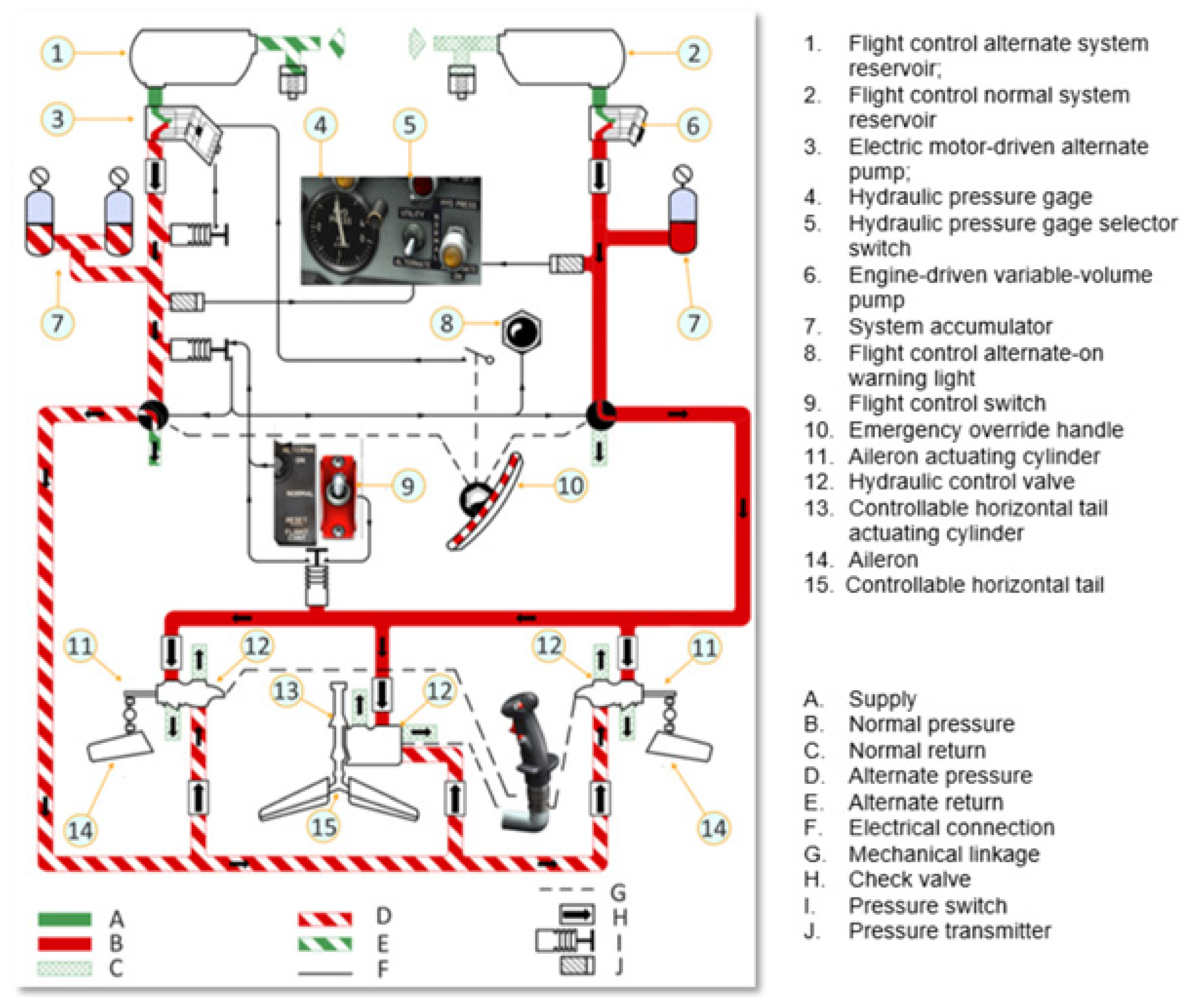
Figure 2 shows the concepts of FBW and redundancy in the F-86F flight control system, where there are two independent boost hydraulic systems: a normal and an alternate system. Here, pilot input is transferred to the actuation hydraulic drives to control several control surfaces such as ailerons, horizontal tails, and elevators.
Along with the development of high-density servo motors, power electronics, and digital control technologies, novel categories of actuation systems, such as electrohydraulic actuation systems and electromechanical actuation (EMA) systems, were introduced. Furthermore, the electric actuation approach gained wide recognition due to significant weight reduction and cost savings, better overall energy efficiency, and improved reliability and maintainability [14].
A study conducted at Cranfield University compared the percentage changes in key parameters (such as mass, power off-take, and other factors) in the EHA and EMA systems (relative to a zero baseline) of an actuation system in an EF2000 combat-type aircraft [5]. While the advantages and benefits of AEA (over conventional aircrafts based on hydraulic actuation systems) were acknowledged in the study, the various challenges in the progression to full electrification were also recognised [5]. Therefore, prior to fully replacing secondary hydraulic and pneumatic systems with AEA systems (in the early 1980s), a hybrid solution was deployed. This was referred to as the more electric aircraft (MEA) approach [4,5,20,21].
With the above in mind, there have been rapid developments in actuation system designs for the AEA and MEA concepts over the past few decades; however, a comprehensive review has not been undertaken to date. This review aims to provide an up-to-date summary of these developments, with critical discussions on the system design, force fight effect on current redundant actuation systems, as well as future research trends in the force fight elimination in actuation systems. Section 1 provides a general overview of the electric actuator system design and a background on its historical development. Section 2 and Section 3 present a detailed discussion of two main categories of actuation systems developed for electric aircrafts, namely electrohydraulic actuator systems and electromechanical actuator systems. Section 4 addresses the force fight present in these redundant actuation systems. Section 5 critically analyses the systems developed to address the force fight effect in redundant actuation systems and presents the future trends in force fight elimination in redundant actuation systems. Finally, in Section 6, the paper concludes with perspectives on current developments that are shaping the future of electric aircraft redundant actuation systems.
Figure 2. Example of a Fly-by-Wire and Redundancy on a flight control system [22].
Aerospace 10 00787 g002

2. Electrohydraulic Actuation Systems

This section of the paper presents electrohydraulic actuator system designs that have been introduced over the years. Some of the leading early EHA systems implemented in aircrafts that have set the architecture and design standards for modern aircraft electrohydraulic actuator systems are discussed in this section. Figure 2 illustrates the booster hydraulic system used in the F86-F Saber [22]. The aircraft contains two systems: normal and alternate. The normal booster hydraulic system has a separate reservoir that is independent of the alternate system, as shown in Figure 2. The transition from a normal hydraulic system to an alternate booster hydraulic system occurs automatically as soon as the pressure in the normal hydraulic system drops below 650 PSI. This will be indicated by a warning light (ALTERNATE ON) on the instrument panel. The alternate booster hydraulic system overrides all functions in case the normal booster hydraulic system fails.
The B-2 advanced technology bomber is one example of an aircraft with EHA [23]. This aircraft has a self-contained quadruplex system that includes hydraulic actuators with direct drive servo valves, electronic actuator loop closures, and redundancy management [24].
Electrohydraulic actuator systems are widely used in aerospace and large commercial aircraft. The EHA approach was initially implemented in the A380 civil aircraft to move its aileron [25]. Since then, several aircrafts Airbus 340, Airbus A400M, Airbus A350, and Embraer KC390 have successfully implemented the EHA system [26]. The EHA system is a pump-controlled system that consists of a motor, hydraulic pump, hydraulic valve, and hydraulic cylinder [27]. These components are all integrated into a single unit. The EHA approach has the advantages of both hydraulic and electronic systems, thus providing weight-reduction benefits, increased efficiency, and reliability [6,28].
Over the past few years, several EHA designs have been developed for electrical aircraft, for example, J. Breit reported on findings from the Experimental Aircraft Project (EAP) program, which examined and compared the functionality of electrohydraulic servo valves (EHSVs) with direct-drive valves (DDVs) actuators for primary flight control [6]. Figure 3 shows the British Aerospace (BAe) EAP actuator flow diagram, with the control valves driven either by EHSV or DDV. Here, four computers control the actuator, where each of the computers compares the position errors to drive an EHSV. Four linear variable differential/distance transformers (LVDTs) measured the actuator position.
In the EHSV assembly, two hydraulic systems (HSs), each of which is associated with two EHSVs, drive the actuator. However, in the DDV assembly, the computer signals from the computer are flux summed to a linear motor that directly drives the tandem main control valve. Therefore, EHA systems with EHSV can sustain operation after one electric failure and one hydraulic failure or after two electric failures. However, EHA systems that are driven by DDVs have the advantage that the loss of a hydraulic power supply does not affect the number of electrical lanes. In other words, EHSVs demand that the actuator is always driven by the two hydraulic systems, whereas the number of electrical lanes in systems that utilise DDVs is not affected by the loss of a hydraulic power source. However, unlike EHSVs, DDVs have limited operating stroke, thus they have wider flow control ports, and hence careful design considerations are needed to control leakage, flow, and pressure gains, as this impacts the actuator performance.
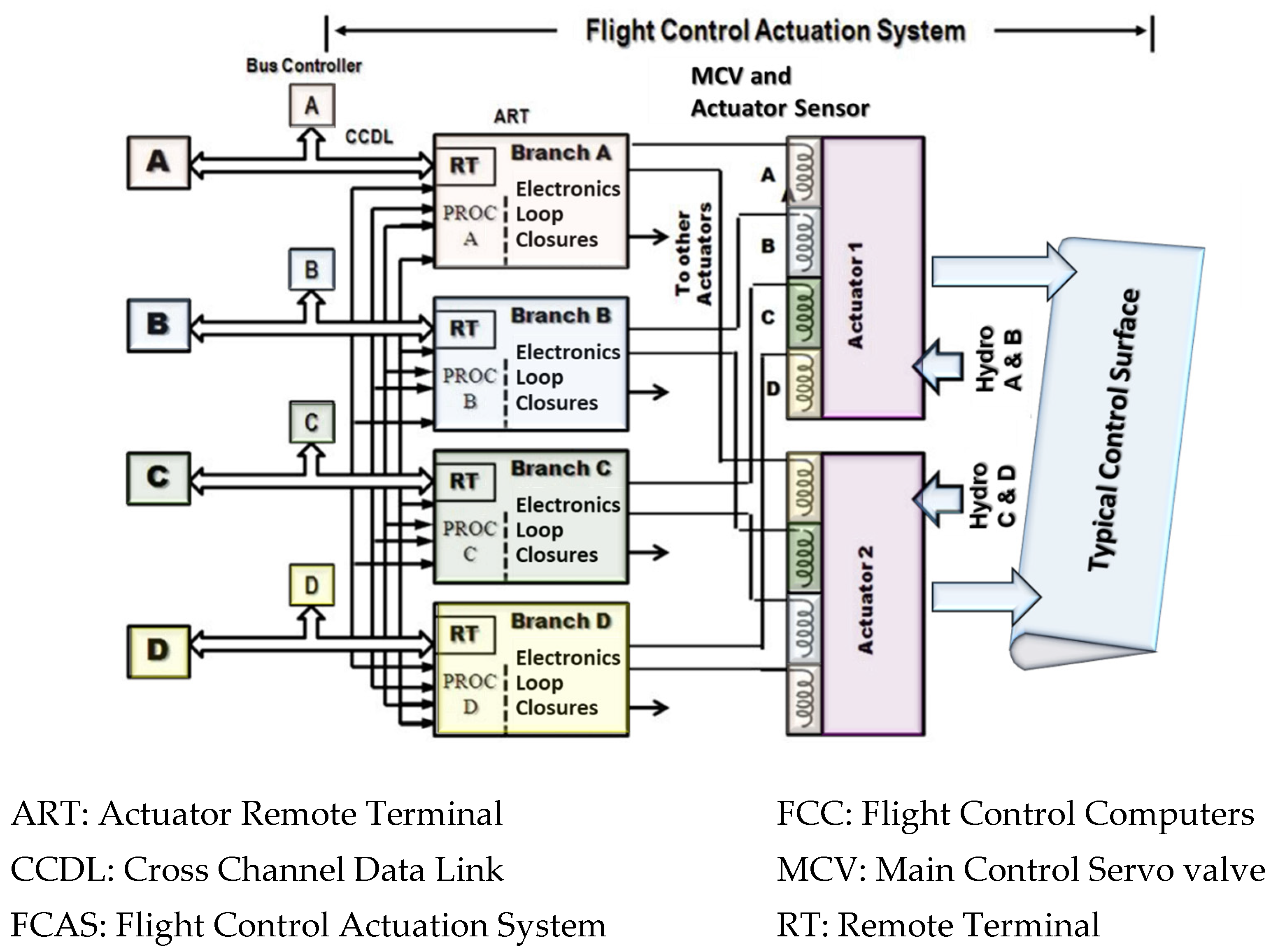
W. S. Schaefe et al. described the actuation system of the B-2 advanced technology bomber, which is an example of the EHA system [23,24]. The system architecture (shown in Figure 4) comprises four on-board computers that compute and generate input commands for the actuation system, as well as perform monitoring, control, and communication tasks. The B-2 bomber aircraft has 11 primary control surfaces driven by actuators that are part of the flight control actuation system (FCAS). The FCAS is made up of actuators themselves and four quadrupled “actuator remote terminals (ARTs)”. These are distributed on each side of the aircraft airframe, thus there are eight ARTs per FCAS. Each ART contains closed-loop electronics for the DDV-driven actuator and numerous quadrupled transducers. Other safety features that were reported include ① the aircraft has two hydraulic systems that alternate to power sister actuators; ② the aircraft has the capability to operate the actuators in either primary, alternate, or bypass mode; and ③ the aircraft has isolation valves to prevent failure progression due to structural failures or module leaks.
The actuation system in the B-2 bomber aircraft is driven by commands from the four on-board computers that also perform fault detection and fault isolation (FDFI) tasks. The computers also provide control and communicate with the other remaining systems. Figure 4 is a block diagram of the B2-bomber’s FCAS architecture. The FCAS includes actuators that are driven by two redundant sets of quadrupled ARTs, with each set operating on one side of the aircraft. There are 11 primary flight control surfaces on this aircraft, each of which is driven by a single-piston actuator that is powered by a DDV and several quadrupled transducers. Each actuator is powered by two hydraulic power sources via a (primary, alternate, or bypass) mode select valve.
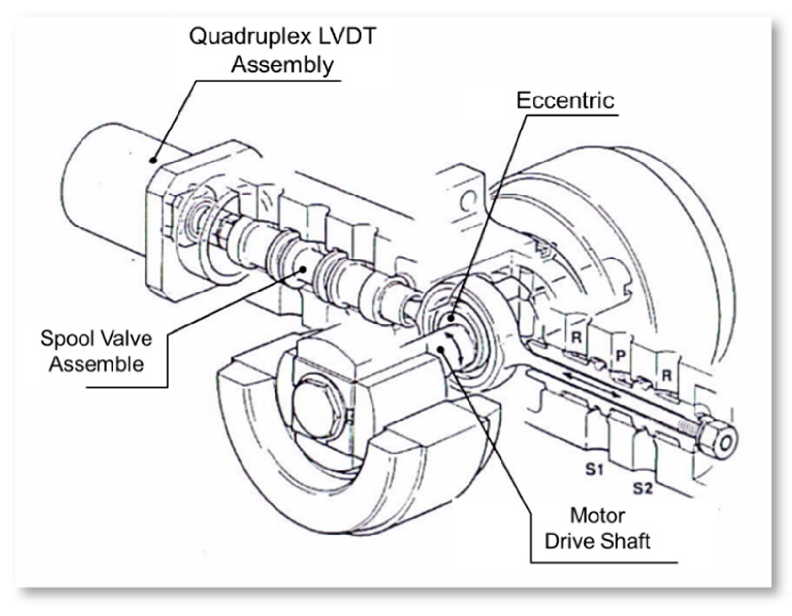
Raval discussed the Fairey direct drive valve (FDDV) approach used in aircraft systems [30]. The FDDV approach is shown in Figure 5. Its relatively large stroke spool is directly driven by two limited-angle brushless DC motors (BDCMs). Each motor stator has two (magnetically and physically) distinct coils, thus resulting in four control lanes. The motors have cylindrical-shaped rotors that are made up of square yokes bonded to four rare earth magnets [30]. Failure propagation from one lane to another is prevented through housing separation, and feedback is provided by the four-channel LVDT module that is mounted on the valve housing.
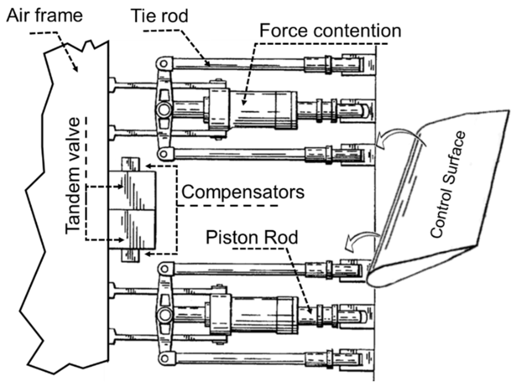
W. E. Boehringer et al. presented a range of hydraulic actuation architectures that ranged from basic to prominent invention assembly [31]. Figure 6 shows the schematic of the actuator attached between a control surface and the airframe. The actuator has a dual simplex assemblage, with a tandem valve, compensators, and a force contention unit. The configuration tolerates dormant failures and any combination of dual mechanical and/or hydraulic failures without disconnecting the control surface. The actuator arrangement satisfies the safety standards for balanced weight removal with only two actuators.
The design proposes an arrangement that does not require weight-balancing and has negligible force fighting (FF) between the delivered output forces. This was achieved by eliminating balance weights from the control surfaces and installing three parallel actuators. These actuators would usually experience FF along the control surface, which could lead to structural damage and failure. To further reduce force contention, the authors proposed the addition of computer-monitored pressure sensors to closely align the actuator positions. The authors also pointed out two other alternatives: an expensive rudder control, which utilises three parallel actuation configurations that are controlled by three hydraulic valves, and a computer-monitored method of dual-simplex actuators (on each surface), which is cheaper and more suitable for aircraft with FBW capability.
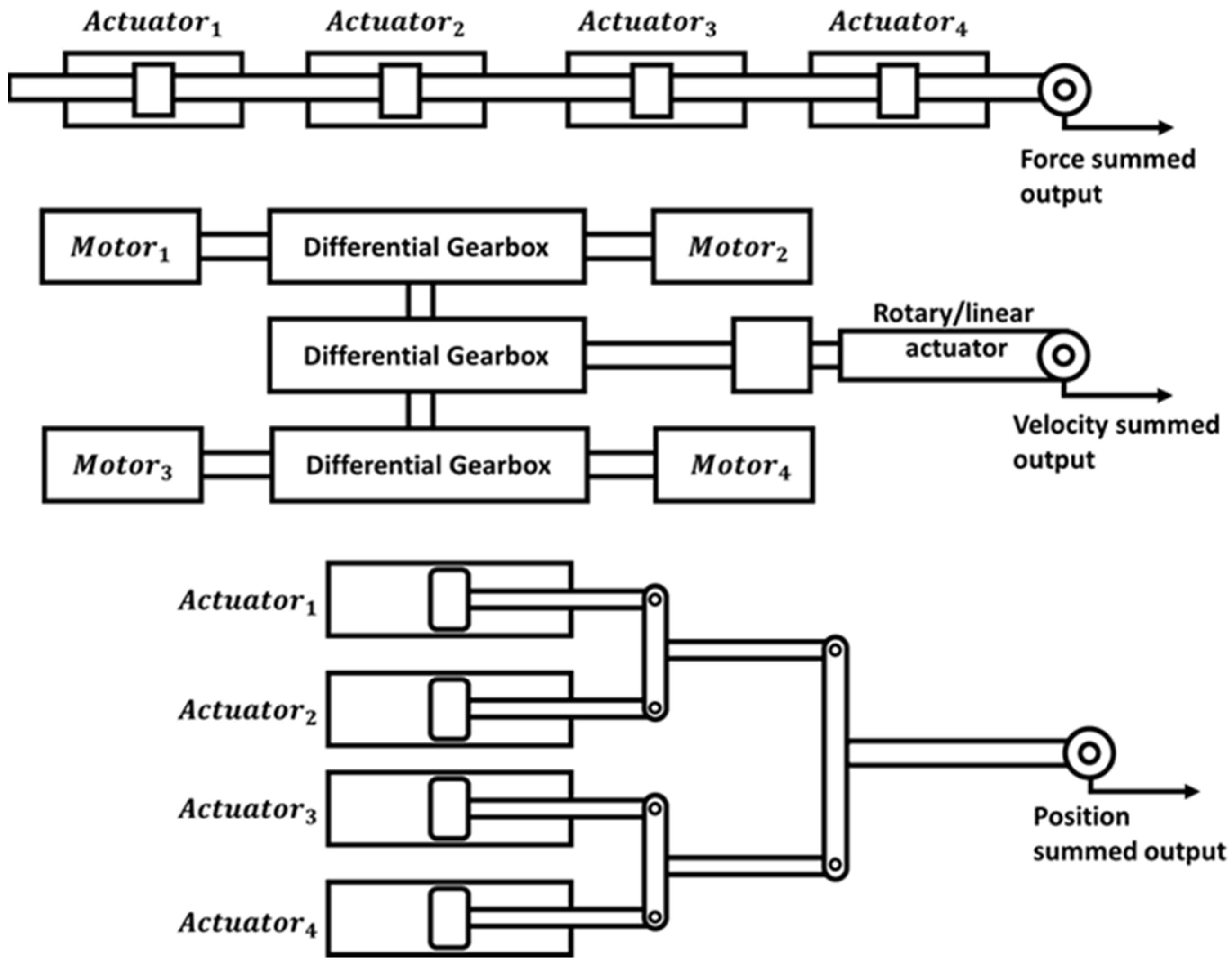
Similarly, C. C. Chenoweth et al. described various methods for designing redundant hydraulic actuator architectures [32,33]. Figure 7 shows systems with mechanisms that deal with mismatched inputs. These include force voting systems, where the output is the average of the input commands; velocity summing schemes, where individual channels cancel input demand differences through differential gearbox assembly; and position summing structures with actuators giving the average of the input commands. In these mechanisms, a single electronic signal drives the active actuator, and (normally) any mismatch poses no concern during operation; however, mismatch becomes a concern (and should be minimized) when active actuators are switched to standby.
The authors also described load sharing, which refers to the ability of multiple actuators to collectively work together to position a common output. Ideally, FF is eliminated if the redundant actuators share the load equally. However, this is not strictly true, as actuators can attain unique positions in response to identical set command values. This unexpected rise in tracking errors is due to one of two factors: the first is mechanical and is due to the actual physical installation, and the second is operational and occurs due to tolerance accumulation between lanes. Since the actuator outputs are locked together (i.e., on one common shaft), FF is unavoidable. To reduce this FF and to ensure satisfactory load sharing between lanes, the authors proposed four approaches: (1) minimising tolerance differences in the feedback loop; (2) compliance between channels; (3) low force gain actuators, which can be achieved through the implementation of low-pressure gain servo-valves or the use of pressure and load feedback paths; or (4) equalization to average load, which is achieved by comparing individual actuator loads to the average load.
The research paper by D. Y. Wang et al. stated that in most cases, primary flight control systems on commercial airliners are configured in parallel force or position-summing configurations [34]. When operating in active/active mode, parallel-force-summing configurations result in serious force fighting between actuators, which must be addressed. However, the parallel-position-summing configuration does not result in force fighting and is suitable for all types of actuators [33]. Furthermore, the authors of [34] proposed position synchronization for hybrid electromechanical actuation systems.

3. Electromechanical Actuation Systems

The development of flight control systems was limited to hydraulic actuation systems due to their reliability and lack of alternatives. However, the development of BDCMs and advances in electronics led to the development of electromechanical actuators, replacing their hydraulic predecessors—the last main nonelectric components in modern aircraft. The development of this technology paved the way for the birth of the all-electric aircraft concept, which is aimed at the consolidation of power sources into one electric power source [35]. The EMA system eliminates the use of hydraulic flow in the actuation that is utilized in EHA systems. The main components of the EMA system are a control unit, an electric motor, and a mechanical transmission method (either a ball screw or gear mechanism). EMA systems can operate without hydraulic pipelines, valves, and hydraulic tanks [36]. Thus, EMA systems provide a range of benefits, including high compactness, reduced weight, high reliability, and reduced noise [13,14,37]. As such, a number of EMA designs have been introduced over the past years. Several programs have also been initiated to analyse the problems, challenges, and the advantages of EMA on next generation electric aircraft [38,39,40,41,42,43,44]. The following section illustrates the EMA systems and concepts introduced over the years for electric aircraft systems.
Holmdahl discussed important aspects of the aircraft actuation system: the reliability and redundancy of EMA systems [39]. The study revealed that a primary reliability concern was the likelihood of developing gearbox jams or other failures in the EMA system. Similar concerns emerged from the “Grumman program” therefore it was recommended that the EMA systems should match the reliability of the dual-tandem EHA system that it is replacing. This requirement translates to developing all-electric actuators with a probability failure rate of less than 10−10 per flight hour [40]. The author also recommended the need for further knowledge when designing weight-competitive, redundant, and reliable gearbox technology. Holmdahl further presented a set of solutions to overcome the issues present in EMA. These solutions were torque-summed assembly with minimum critical gears, redundancy provision with isolation capability by dividing surfaces into two or more sections, independently actuating each section using smaller EMA systems, and blending various summing architectures with appropriate use of clutches or brakes [39]. Consequently, new EMA system designs should match the performance of their existing hydraulic equivalents, with fail-operational and fail-safe operation specifications. Thus, the probable acceptable system configuration would be a quad-motor assembly that meets the full performance specification following a motor failure and a degraded “get home capability” following a second motor failure.
One of the main contributors that has addressed hydraulic and electromechanical actuators is Georgia and Sundstrand Corporation. The cooperation, together with USAF Flight Dynamics Laboratory, developed a dual torque-summed EMA system that drives a single ball-screw electromechanical actuator to control the left-hand aileron control surface on the C-141 aircraft. The developed system is shown in Figure 8. This program was initiated in 1982. In this program, a series of system developments and flight test programs were conducted on C-141 and C-130 aircrafts. These developments and tests were discussed and reported in several articles [38,39,40,45,46]. Alden summarized the laboratory and flight test details and provided the failure characteristics of each actuation system implemented on aircraft under the program [45]. Smith also presented the importance of considering the duty cycle of an electric actuation system implemented on aircraft under the program [46].
The “NASA Experimental Aircrafts” is another example of a program that described the development of all-electrically actuated aircraft, namely X-33, X-37, X-38, and X-43A. The first of these programs was the “Advanced Technology Demonstrator Test Vehicle” program, which described the X-33 aircraft that uses the EMA system. The EMA system of the X-33 aircraft was developed by “Lockheed Martin”. It was classified as a high-risk vehicle because of the new actuation method used. To reduce the failure risks involved, reconfigurable control laws were developed so that if one of its eight control surfaces were to fail, the vehicle would be controlled by the remaining seven healthy control surfaces [47].
The second program was the “Integrated Vehicle Health Management Technology Experiment” for the unpiloted X-37 vehicle [48]. The unpiloted X-37 program also analysed the operation of the EMA system implemented in the unpiloted X-37. The program performed real-time FDFI experiments on the electric power source and electromechanical actuation system as the vehicle orbited the earth for 21 days before landing [48]. The “Proto-Flight Vehicle 201 (V-201)” is another program that examined the implementation of EMA systems in fight vehicles [49]. The program examined the development of the complex seven single-fault-tolerant-actuated subsystems to assess the repeated fins deployment and storage to allow for orbiter doors closure [49]. Therefore, the main aim of the project was to perform development tasks on the “International Space Station Crew Return rates in electric Vehicle”, one of which was the X-38 aircraft.
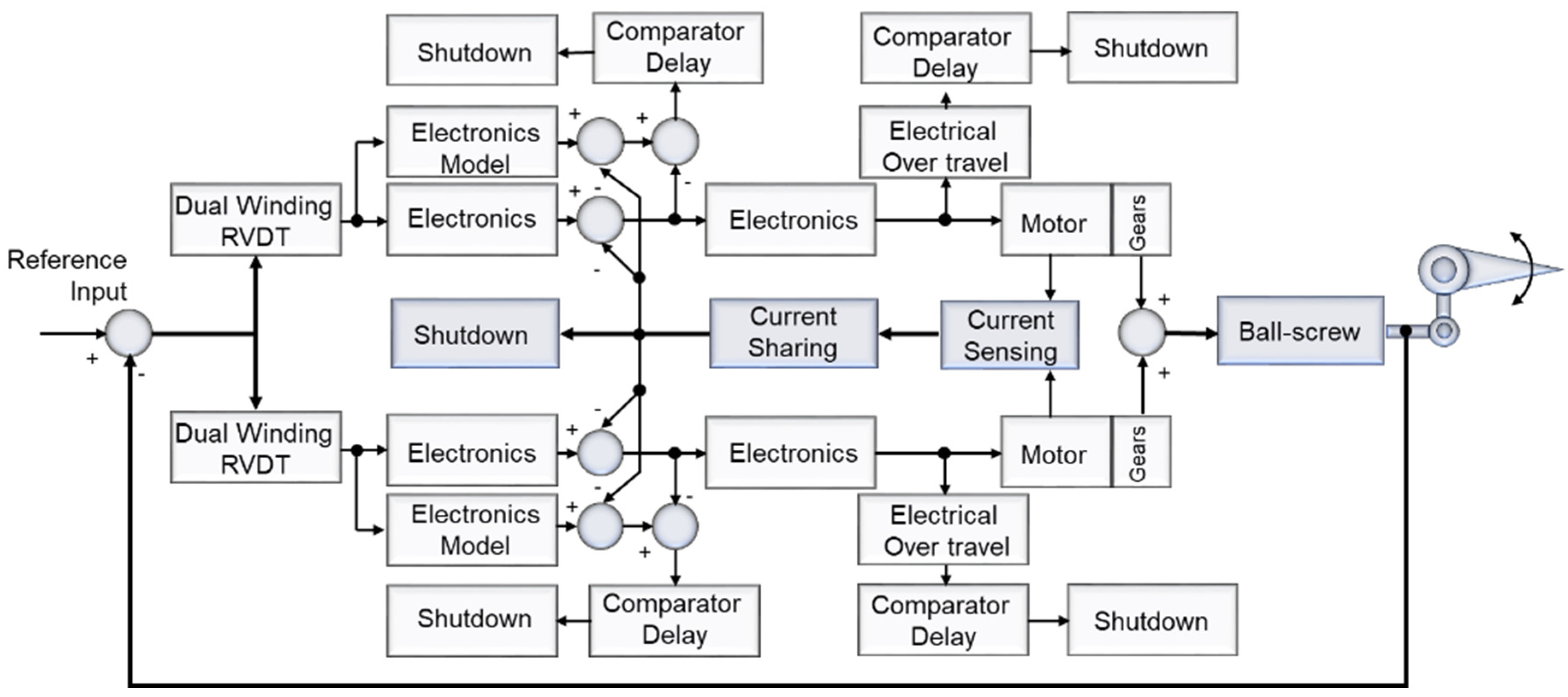
Hagen et al. examined X-38’s EMA system that drove the lower rear flaps of the crew rescue V-201 [50]. Two surface flaps and the associated actuation subsystem units’ functionality were examined. Each surface has four controllers to control the three housed motors in the subsystem unit. The controllers run online simultaneously, communicating with each of the three motors that power each of the EMA systems that drive the flap. In the design, the controllers include motor synchronization codes to prevent force fight between them. Furthermore, Lin et al. identified the tests required to adequately characterize and model the on-board EMA systems [51]. The Hyper-X program is another project that examined EMA utilization in X-43A [52]. The X-43A has five EMA systems, four of which are identical onboard actuators that are used to move the two wings and the two rudders, and one actuator that is used to move the cowl door. All actuators use three-phase BDCMs that are capable of driving 3390 Nm loads. The hood actuators differed from the other four by having longer wire bundles, oblique tailstocks, and modified housing.
In 2000, the US Air Force, the US Navy, and NASA jointly sponsored the “Electrically Powered Actuation Design (EPAD)” program to develop and flight test three aileron actuators on the NASA F/A-l8B Systems Research Aircraft (SRA) [53]. Of the three actuators, one was developed and tested under real flight conditions. The actuator was subjected to a wide range of real aircraft operations, including flight changes, trim variations, and actual flight dynamics. The performance of the actuator was compared with that of its hydraulic equivalent on the other aileron. The results showed that EMA performance and operation were virtually identical to those of the standard hydraulic actuator [53].
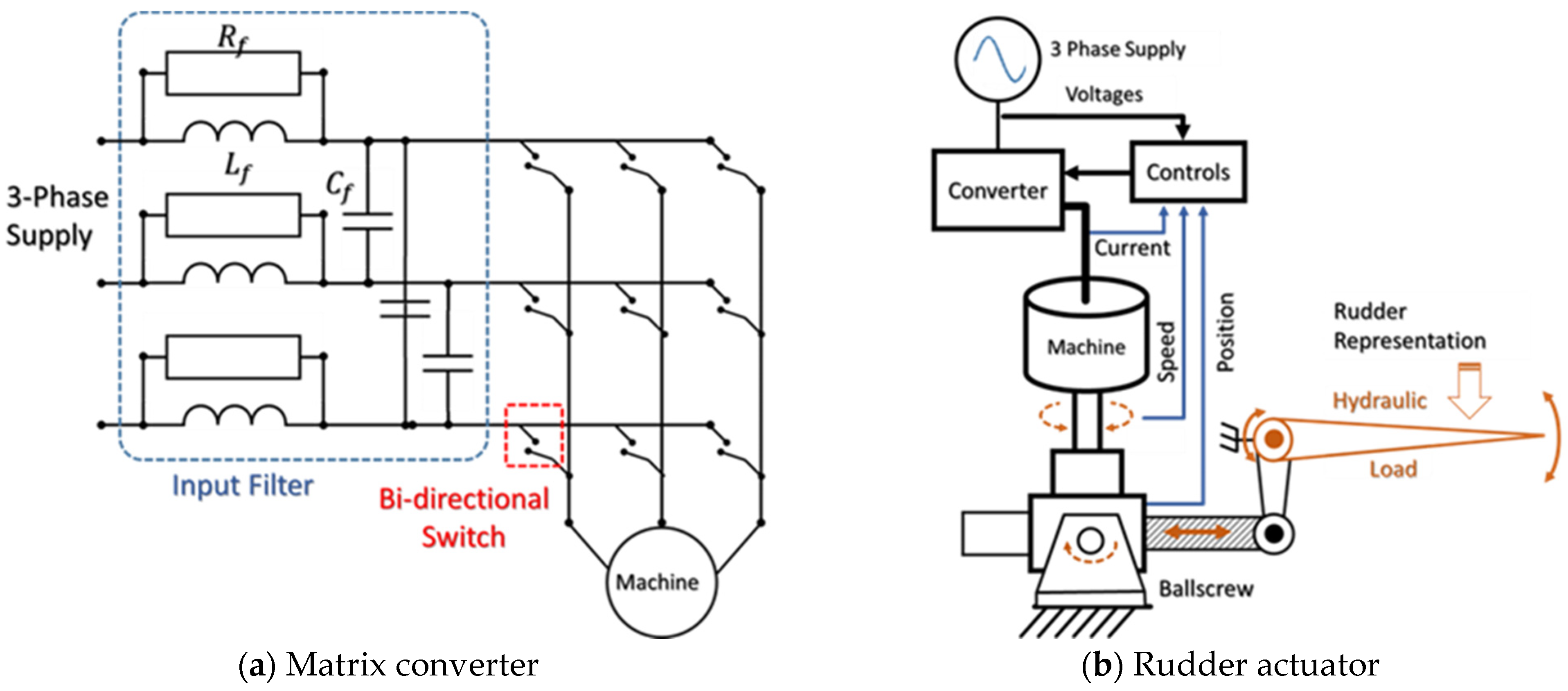
The actuator design described in [54] is another example of an EMA system. It was jointly developed by Smiths Aerospace (Wolverhampton) and the University of Nottingham. Figure 9a,b show the matrix converter design and rudder actuation of the EMA system, respectively. The main aim of the research was to validate the suitability of using matrix-driven motors in an EMA design to drive the rudder of a civil aeroplane with a maximum load of 159 kN [54,55].
“X-45A Joint Unmanned Combat Air System (JUCAS)” is another program set up to develop an EMA system; it was discussed by Davidson in [56]. The study gave an overview of the eighteen linear electromechanical actuators that were designed to move the six-trailing edge elevons, the two-yaw thrust vectoring nozzle, the nose wheel steering, and the landing gear. The study also reported test results for the autonomous steering guidance algorithm during taxiing, take-off, and landing [56].
The “Large Electromechanical Actuation System (LEMAS)” Program also examined the development of EMA systems for electric aircrafts. This program was jointly funded by Lucas Aerospace and the UK Department of Trade and Industry [57,58]. The program investigated the use of a linear ball-screw arm assembly to move the spoiler. The design initially incorporated a permanent magnet BDCM to drive the arm assembly before utilizing 4-phase switched reluctance motors.
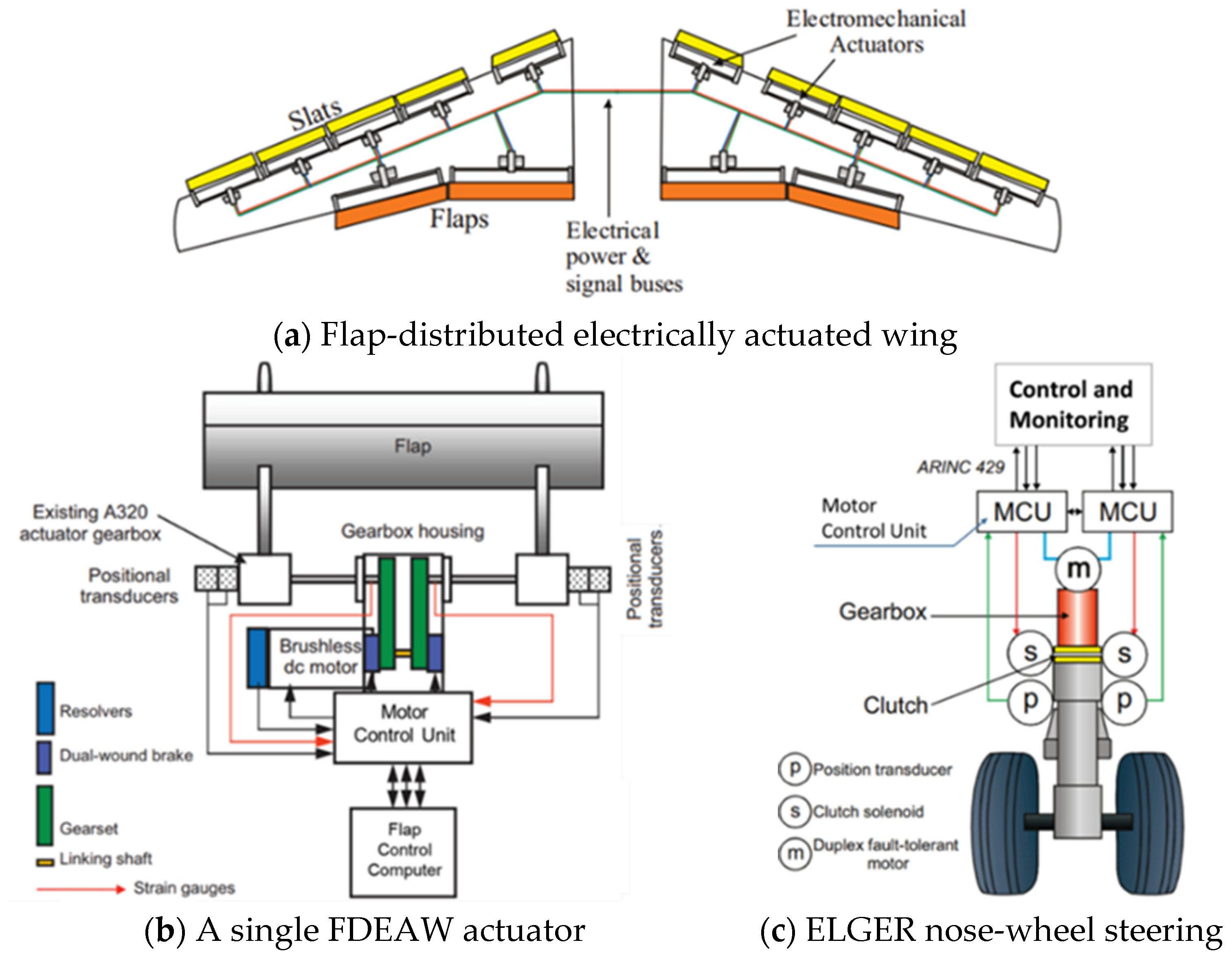
The Newcastle University School of Electrical, Electronic, and Computer Engineering group has also made several contributions, presenting several electromechanical actuators for different loading designs, with motors driven by matrix converters. For example, Bennett et al. described the use of an actuation system with a maximum load of 34 kN to drive one of the four flaps on a 180-Ton (mid-sized) commercial aircraft [51]. In 2010, Bennett et al. further described dual-redundant systems for a “Flap Distributed Electrically Actuated Wing (FDEAW)” system and an “Electric Landing Gear Extend and Retract (ELGER)” system [59]. The FDEAW systems are illustrated in Figure 10a,b. The FDEAW system was designed to output 72 Nm through a 37:1 gearbox assembly. Similarly, the ELGER system was designed to deliver torques in the order 7 kNm at speeds of   18.5 ° / s e c . The ELGER system is shown in Figure 10c [60,61].
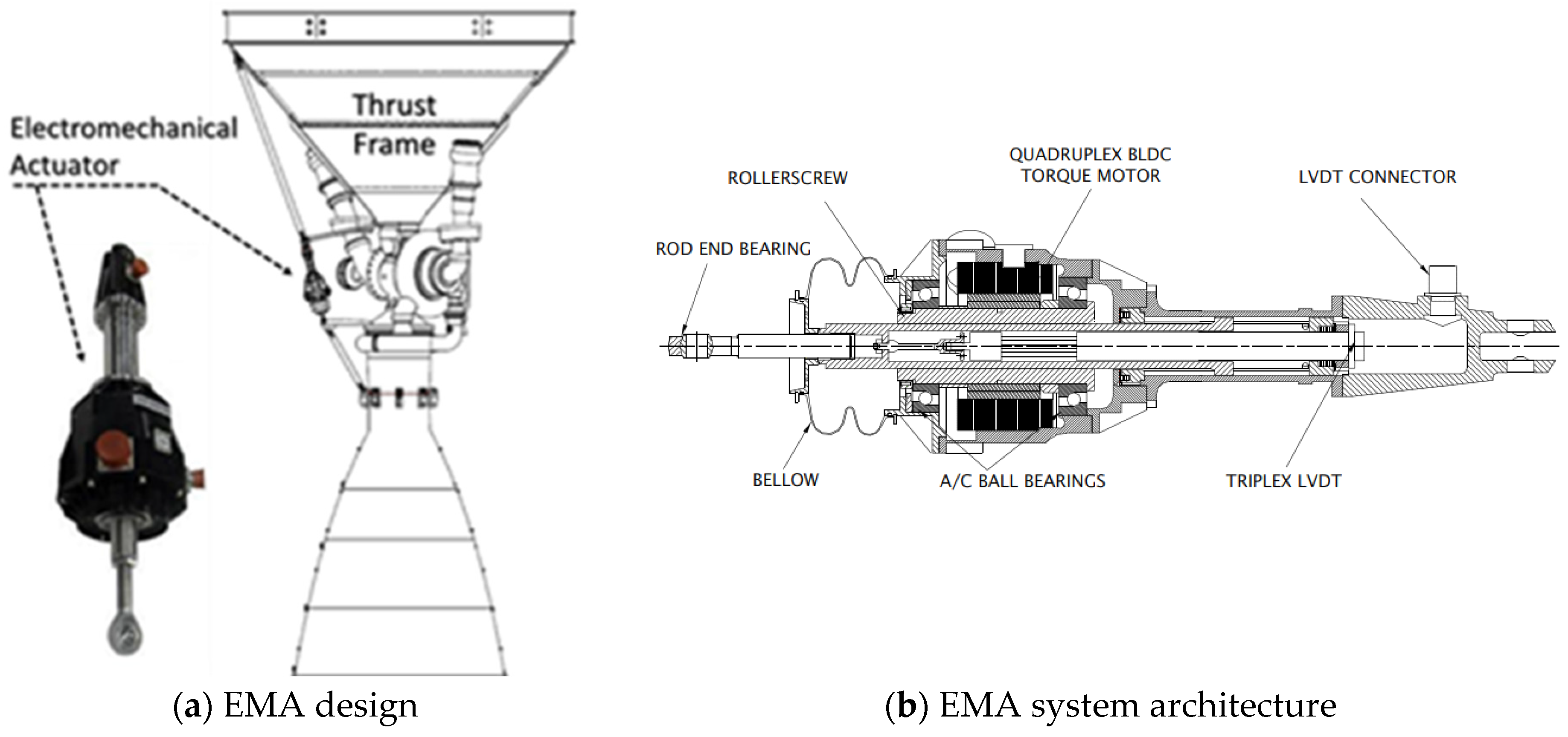
The Vikram Sarabhai Space Centre (VSSC) also introduced a set of interesting EMA system designs. The VSSC is a major space research centre of the Indian Space Research Organisation located in Thiruvananthapuram (The state of Kerala). The centre is focused on the development of rockets, launch vehicles, and space vehicles for India’s satellite programme. Some of the VSSC’s developments include the lower stage thrust vector control actuation system on the GSLV, PSLV, and LVM3 satellite launch vehicles of the Indian satellite carrier rockets. In a series of publications, Prasad et al. and Ganesh et al., researchers from the VSSC, introduced two linear electromechanical actuator assembly designs that are utilised in thrust vector control applications [62,63]. The design developed by Prasad et al. has the capability of generating a maximum force of 40 kN, whereas the design introduced by Ganesh et al. can generate a maximum force of 96.7 kN [62,63]. Figure 11a illustrates the EMA developed by Prasad et al. and Figure 11b shows the architecture of the developed EMA system.
The development of power drives for planetary roller-screw gear electromechanical actuators was described by Biryukov et al. and Nosov [65,66]. The two studies presented by these authors highlighted that this approach improves the reliability and accuracy of the equipment used for installing and integrating the large mass and size mechanisms associated with a rocket carrier. The literature further reported on electromechanical actuator research and development programs performed by Technodinamika Holding in Russia. These research and development activities were conducted to replace hydraulic systems such as the landing gear’s hydraulic extension, the retraction drive system in the “Tupolev Tu-204 aircraft”, and the thrust-reverser on the “Aviadvigatel PD-14 engine”. Figure 12 shows the Aviadvigatel PD-14 engine architecture.
The reliability of electric drive systems is another vital aspect of electric aircraft, given that the failure of electric drive systems can endanger the safety of the aircraft. Thus, fault-tolerant electric drives are important in electric aircraft design. A number of designs have been introduced to improve the reliability of the electric drive system in electric aircraft. A four-leg three-phase inverter developed by [67] is an example of a system developed to increase the reliability of electric drive systems. In this, design a four-leg three-phase inverter is utilized in the drive system where the system handles the failure of all the power switches connected to the positive or negative rail of the dc-link. Additionally, the proposed design has the capacity to supply unipolar current waveforms under post-failure conditions, which supplies the required rotating field to generate the electromagnetic torque. A fault-tolerant control (FTC) system developed by Suti et al. [68] to identify electrical faults in a three-phase permanent magnet synchronous motor is another design developed to enhance the reliability of electric drive systems. The system utilizes current signature techniques for fault diagnosis and isolation by analysing the current phasor trajectory in the Clarke plane. The proposed system is also capable of detecting the fault in six electrical cycles. The system uses the rotor current frame transformation control approach to improve the post-failure performance.
The open-phase fault-tolerant permanent magnet synchronous machine [69] is another example of a system developed to increase reliability. The proposed approach uses current prediction methods for open-phase fault identification and the proposed system is capable of detecting the fault within fifty microseconds. Post-fault operation in this design is achieved using the four-switch operation of a standard inverter.
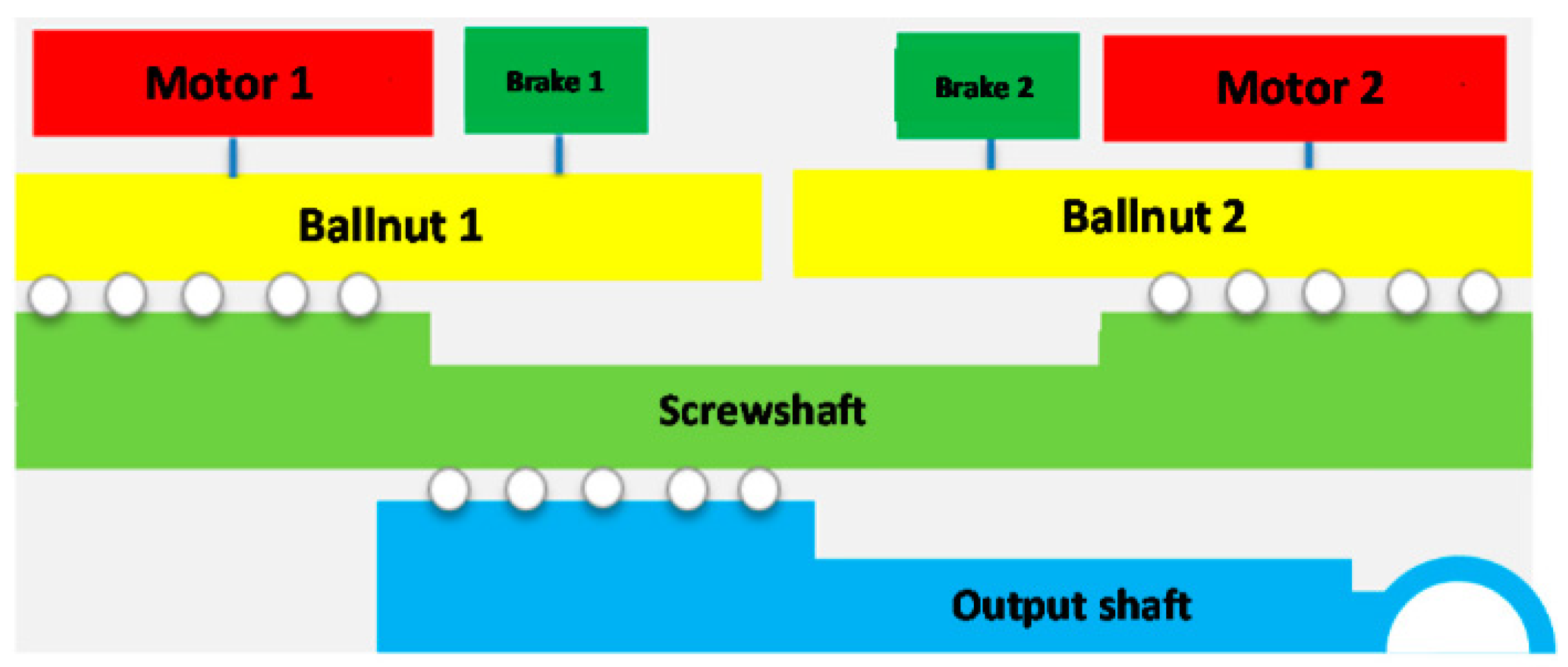
Mechanical drive failure in EMA is a major challenge in the development of EMA systems for aerospace applications. Many studies have been conducted to develop systems and methods for identifying and preventing the failure of mechanical drive systems in EMA [70]. Condition monitoring system for EMA with fault-tolerant architecture developed by the authors in [71] is one of the research efforts made to address the issues of mechanical drive failure in EMA. In the proposed EMA architecture, two permanent magnet synchronous motors are coupled with differential ball screws in a speed-summing method. Two electronic control units (ECUs) are utilized in the system with condition monitoring algorithms and control functions that are based on three nested loops on the speed and currents of the motors and the position of the output shaft. The system is capable of operating after an electrical drive fault (motor or inverter) or mechanical jamming. A differential ball-screws-couplings-based approach is used for mechanical energy transmission in the developed EMA. The system engages the two motors via rotor-integrated ball-nuts as shown in Figure 13. The screw shaft contains three threaded sections. The screw shaft is connected to the output shaft via an internal threaded section. Figure 13 illustrates the system architecture of the developed fault-tolerant EMA.
The Reliable Electromechanical actuator for PRImary SurfacE with health monitoring (REPRISE) project has introduced a health monitoring system to identify the degradation of mechanical components, particularly ball screw transmission and nut assembly in EMA [72]. Statistical process control methods are used for the development of health monitoring systems. The proposed system only uses EMA motor phase currents for the condition monitoring ball screw transmission and nut assembly of the EMA.
The model-based prognostic algorithm developed for mechanical transmission freeplay detection of EMA [73] is another system designed to predict failure in mechanical drives in EMA. The proposed model employs limit cycle characteristics such as amplitude and frequency to estimate freeplay. The proposed algorithm model has shown higher accuracy under greater freeplay conditions. However, the accuracy in small and intermediate mechanical transmission freeplay has reduced.
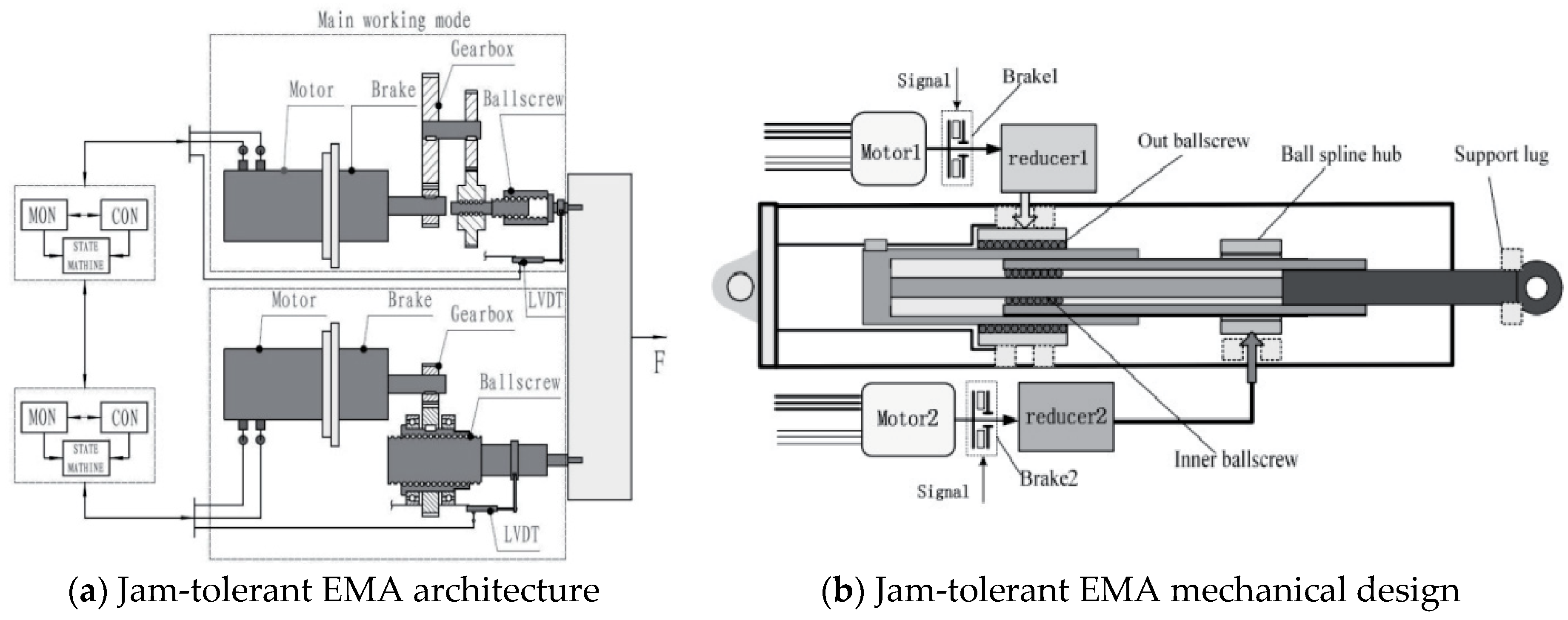
The Jam-tolerant electromechanical system developed by Yu et al. is another design developed to address the mechanical failure issue in EMA [74]. The system contains two power modes: normal-operating and jam-tolerant. The actuator is designed with a dual ball-screw assembly integrated with a ball spline hub. The system architecture of the developed EMA is shown in Figure 14a. The system contains two motors, two breaks, two gear reducers, two ball-screw assemblies with outer and inner sections, and a ball spline hub, as shown in Figure 14b. The brakes are used to lock the output axle of the respective motors, depending on the operating mode (normal mode or failure mode) of the EMA.

4. Force Fight in Redundant Actuation Systems

In an aircraft, the actuation system is a key component that manipulates the altitude and flight path of an aircraft [75]. All modern aircraft actuator systems need to maintain high safety and reliability [76,77]. Thus, these factors have become fundamental requirements in modern aircraft designs, particularly architecture consolidation of multiple channels within an actuation system. The parallel redundant actuation method has been applied widely, with two modes of operation: active/active and active/passive [78,79,80].
In the active/active mode, actuators function while also providing actuation for the system. However, in the active/passive mode, only a single actuator operates. While operating in the active/active mode, control surfaces that are driven by multiple actuation systems are likely to experience a force-fighting effect. This has dangerous effects on the aircraft system as it can generate tracking accuracy errors and damage the control surface [81]. Therefore, force fighting has become a trending research area in aircraft actuator system design.
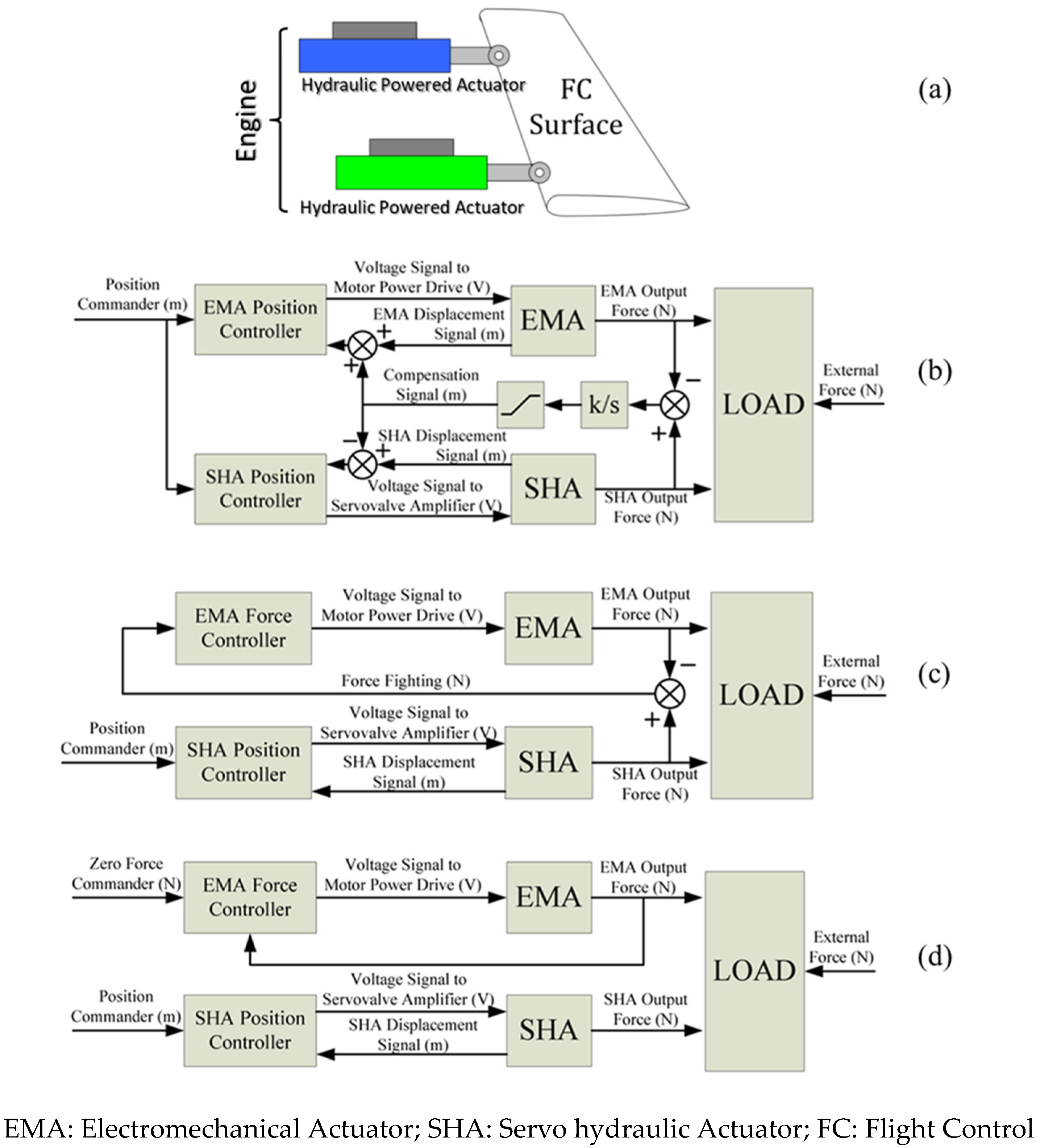
Although many research groups have described torque-summed architectures, very few have addressed the possibility of FF between the redundant lanes. For example, the authors in [82,83,84] investigated suitable control strategies for redundant actuation systems using different actuator technologies to achieve static force equalization (FE). Figure 15a shows a typical hybrid actuation system. The performance of a virtual redundant actuation test bench was verified by experimental results. The testbed evaluated the cause of static force fighting in three different “Force Equalization” control strategies. These strategies are:
(1)
Position control of a combination of servo-hydraulic and electromechanical actuators, where FF signals were used to compensate position feedback signals by tuning the position sensors offsets (Figure 15b);
(2)
Force control of a combination of servo-hydraulic actuator (SHA) and electromechanical actuator (EMA), where motor current control achieved faster control response (Figure 15c);
(3)
No-load control of a combination of servo-hydraulic and electromechanical actuators, where FF is cancelled as the EMA did not have a direct influence on the load position (Figure 15d).
L. Wang further proposed FE control strategies for a hybrid EHA and EMA system that drives a single aileron control surface, pre-validated it on a virtual test bench, and then experimentally compared the two strategies (integrating a force fighting signal to compensate for the position control and operating in master/slave modes) [83]. One drawback of this study is the fact that it did not consider power source consolidation and utilised both hydraulic and electric power sources, as shown in Figure 16. The study considered a parallel summing arrangement of the EHA and the EMA, confirmed the significant effects of the strategies on static FE, and proposed that future studies should focus on dynamic FE.
J. R. Hoffman assessed the suitability of a passive electromechanical test rig in reproducing the dynamics that EMA systems might experience in various aerospace applications [85]. Although the rig omitted some of the effects an actuator might experience in flight, it included most of the impactful characteristics that are important in the early phases of testing. Furthermore, Wobble replicated a spring-mass-damper test rig to capture first-order flight system responses and reported that a linear model is capable of reproducing very accurate characteristics [86]. The author reported that the approach could be expanded to address FF in a number of EMA systems in future aerospace vehicles.
Similarly, Reham et al. have taken the redundancy concept a step further and argued that higher reliability can only be met by the inclusion of a dissimilar redundant system to avoid common failure modes [87]. This is to avoid common failure modes andThey gave the example of the actuation system on the A380, which comprises of two actuation networks: electric and hydraulic. However, control surfaces that are driven by manipulators (rigidly connected to the control surface) with different driving principals result in FF between the two actuators. To solve this FF issue, the authors proposed implementing model reference adaptive control to synchronise the motion of the conventional hydraulic actuation system and the EHA system. With this system (illustrated in Figure 17), Reham et al. have reported performance improvements with some oscillatory behaviour due to high gain adaptation.
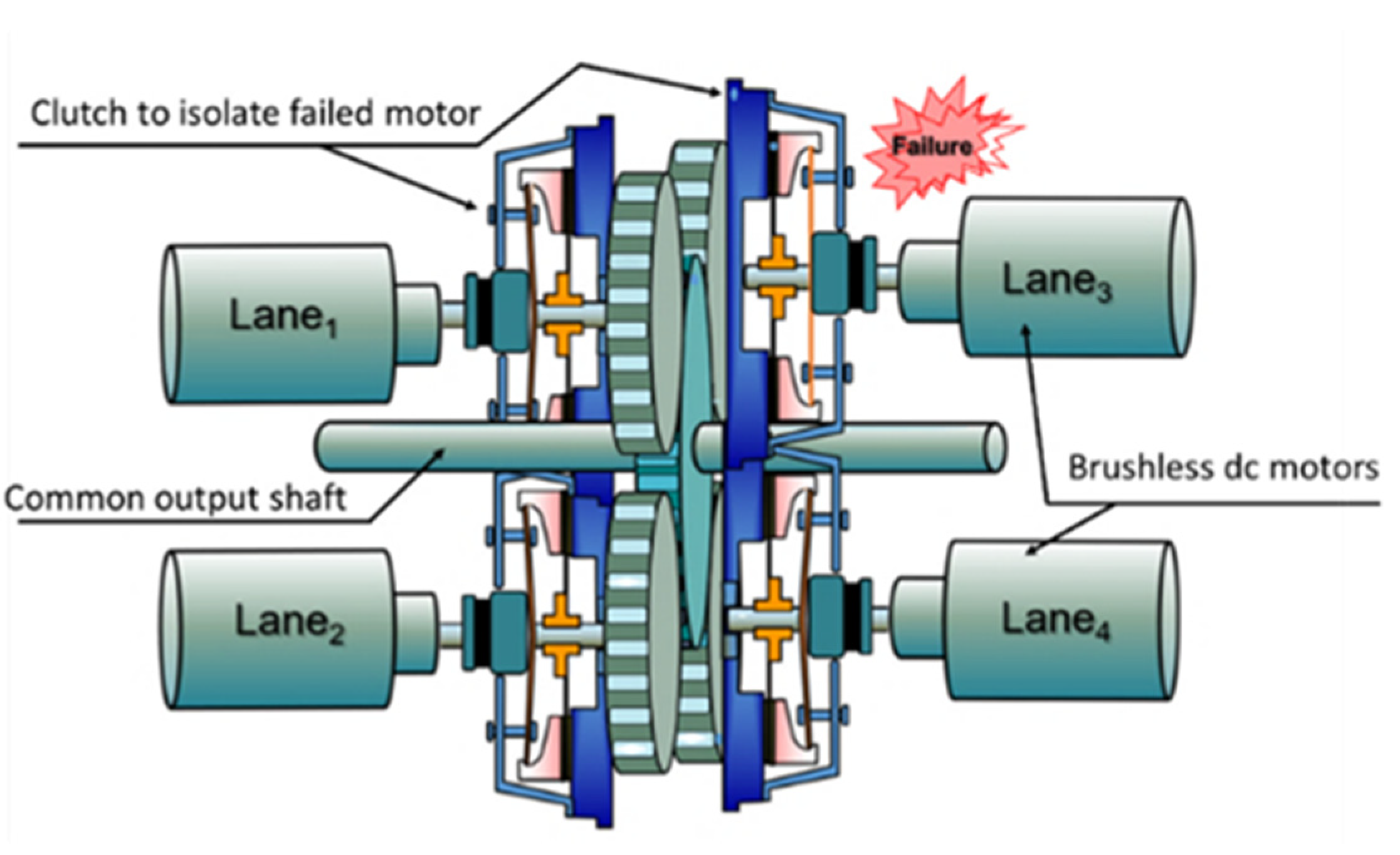
As designs of actuators with redundancy are becoming a normal trend, more researchers have started focussing on addressing the possibility of FF between mismatched lanes. One of the most recent approaches was reported in [88], where a comprehensive study was conducted to investigate FF in the four-lane torque-summed electromechanical architecture shown in Figure 18. The design offers redundancy in lane failures and hence meets the expected fail-operational/fail-safe specification. To ensure total motor isolation, clutches were included in the design to physically disconnect faulty lanes [40].
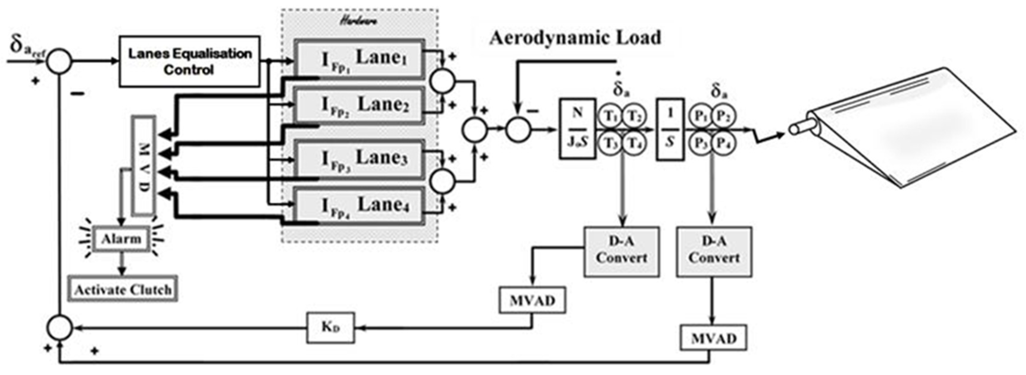
The study considered commercial motors and feedback transducers with high tolerances. The analysis considered extreme cases where motors delivered extreme torques and feedback transducers experienced high tolerances [88]. Two types of architectures were presented and compared: one considered FE while the other did not consider FE. Figure 18 shows the four-lane consolidation and Figure 19 shows the control system block diagram of the FE architecture. Architectures with FE were more effective at reducing the force fight.

5. Trends in Redundant Actuation Systems Design

A limited number of studies have reported and recognised the limiting effects of force fighting in redundant systems. For example, Boehringer et al. addressed force fight in a hydraulic system [31]. Refs. [31,32,33,34] have also recognised the presence of force fights in hydraulic systems. Furthermore, Lin et al. utilised motor synchronization to prevent force fight between the motors on the actuator that drove the flap on X-38 [51]. Similarly, Buccie et al. recognised the effect of possible force fight in redundant actuation systems operating in active/active mode [81]. Different control strategies were also investigated [81,82,83,84] to achieve static force equalization in redundant actuation systems with different technologies. Other studies have implemented different control techniques. For example, [87] introduced model reference adaptive control to synchronise the motion of the HA and EHA systems, and [88] used a lanes equalization controller with the averaged feedback transducer signal. This lanes equalization was most effective at reducing lane disparities due to variations in motor parameters as well as drift in feedback transducers.
Based on the reviewed literature, several studies have described different systems with different levels of redundancies and assumed different control techniques to either control the actuator or eliminate any variations between the redundant lanes. Therefore, future studies will require continued exploration of the possibilities of applying different control techniques and feedback strategies to torque-summed or other alternative architectures to eliminate the force-fight effect.

6. Conclusions

Aircraft controls have developed from totally manually operated to sophisticated self-repairing smart systems. This review reports on the outputs of leading international research and development programs, ranging from the prior FBW era to current all-electric smart developments.
The literature reveals that only a limited number of studies have reported and recognised the limiting effects of force fight in redundant systems that are operating in active/active mode. Various approaches have been used to overcome such limitations. These include motor synchronization to prevent force fight between the motors and control strategies to achieve static force equalization, such as model reference adaptive control and controller with averaged feedback signals to reduce lane disparities due to inherent disparities and drift in feedback transducers. Therefore, future studies will require continued exploration of the possibilities of applying different control techniques and feedback strategies in various architectures to eliminate the force-fight effect.

Author Contributions

The two authors work closely on electromechanical actuation systems and robotics, and in this review. F.Y.A. is the corresponding author and contributed to all aspects of this research. and M.M.K. contributed to this research, particularly to the work related to the more electric aircraft development. All authors have read and agreed to the published version of the manuscript.

Funding

This research received no external funding.

Conflicts of Interest

The authors declare no conflict of interest.

Abbreviations

ARTActuator Remote Terminal
AEAAll Electric Aircraft
BAeBritish Aerospace
BDCMBrushless DC Motor
C f Input Filter Capacitance
DDVDirect-Drive Valve
EAPExperimental Aircraft Project
EHASElectrohydraulic Actuation System
EHSVElectrohydraulic Servo Valve
ELGER systemElectric Landing Gear Extend and Retract System
EMAElectromechanical Actuator
EPAD ProgramElectrically Powered Actuation Design Program
FBW Fly-by-Wire
L f Input Filter Inductance
JUCAS ProgramJoint Unmanned Combat Air System
K D Velocity Feedback
LEMAS ProgramLarge Electromechanical Actuation System Program
LVDTLinear Variable Differential/distance Transformer
MEAMore Electric Aircraft
N Gearbox ratio
SHAServo-Hydraulic Actuator

References

  1. Xie, Y.; Antonios, T.; Dan, Z.; Jason, G. Review of hybrid electric powered aircraft, its conceptual design and energy management methodologies. Chin. J. Aeronaut. 2020, 34, 432–450. [Google Scholar] [CrossRef]
  2. Boll, M.; Corduan, M.; Biser, S.; Filipenko, M.; Pham, Q.H.; Schlachter, S.; Rostek, P.; Noe, M. A holistic system approach for short range passenger aircraft with cryogenic propulsion system. Supercond. Sci. Technol. 2020, 33, 044014. [Google Scholar] [CrossRef]
  3. Ojeda-Rodríguez, A.; González-Vizuete, P.; Bernal-Méndez, J.; Martín-Prats, M.A. A Survey on Bidirectional DC/DC Power Converter Topologies for the Future Hybrid and All Electric Aircrafts. Energies 2020, 13, 4883. [Google Scholar] [CrossRef]
  4. Li, J.; Yu, Z.; Huang, Y.; Li, Z. A Review of electromechanical actuation system for more electric aircraft. In Proceedings of the 2016 IEEE/CSAA International Conference on Aircraft Utility Systems (AUS), Beijing, China, 10–12 October 2016. [Google Scholar]
  5. Jones, R.I. The More Electric Aircraft-Assessing the Benefits. Proc. Inst. Mech. Eng. Part G J. Aerosp. Eng. 2002, 216, 259–269. [Google Scholar] [CrossRef]
  6. Breit, J. Systematic Approach to an Improved Electrical Power System Architecture for a Future More Electric Airplane; SAE International: Warrendale, PA, USA, 2021; pp. 1–11. [Google Scholar]
  7. Glass-Hooper, D.T. The elctric control of large aeroplanes. Flight 1916, 8, 1118–1119. [Google Scholar]
  8. Howard, R.H. Automatic Flight Controls in Fixed Wing Aircraft-The first 100 years. Aeronaut. J. 1973, 77, 533–562. [Google Scholar] [CrossRef]
  9. Cronin, M.J. The prospects and potential of all electric aircraft. In Proceedings of the AIAA, Aircraft Design, Systems and Technology Meeting, Fort Worth, TX, USA, 1–17 October 1983. [Google Scholar]
  10. Kammermann, J.; Bolvashenkov, I.; Tran, K.; Herzog, H.G.; Frenkel, I. Feasibility Study for a Full-Electric Aircraft Considering Weight, Volume, and Reliability Requirements. In Proceedings of the International Conference on Electrotechnical Complexes and Systems (ICOECS), Ufa, Russia, 27–30 October 2020. [Google Scholar]
  11. Patel, V.; Buccella, C.; Cecati, C. Analysis and Implementation of Multilevel Inverter for Full Electric Aircraft Drives. Energies 2020, 13, 6126. [Google Scholar] [CrossRef]
  12. Viswanathan, V.; Knapp, B.M. Potential for electric aircraft. Nat. Sustain. 2019, 2, 88–89. [Google Scholar] [CrossRef]
  13. Miller, F.L.; Emfinger, J.E. Fly-By-Wire Techniques; Air Force Flight Dynamics Lab, Air Force Systems, Command Wright-Patterson Air Force Base: Fairborn, OH, USA, 1967. [Google Scholar]
  14. Sutherland, J.P. Fly by Wire: Flight Control Systems. In Proceedings of the Joint Meeting of Flight Mechanics and Guidance and Control Panels of AGARD, Oslo, Norway, 3 September 1968. [Google Scholar]
  15. Larry, D. North American F-86 Sabre; The Aviation History Online Museum: Online, 2013; Available online: http://www.aviation-history.com/north-american/f86.html (accessed on 17 September 2021).
  16. Rudder, S. Boeing 727-228; JetPhotos: Harlingen, The Netherlands, 2016. [Google Scholar]
  17. Warbird, “USAF History: F-4 Phantoms at Tinker AFB”; Vintage Aviation Publications: Huntington, IN, USA, 2017.
  18. Peitzmeier, H. F-104 Starfighter; Airplane Driver’s Network: Germany, 2018. [Google Scholar]
  19. Warbird, “F-105 Thunderchief”; Vintage Aviation Publications: Huntington, IN, USA, 2017.
  20. Thapa, N.; Ram, S.; Kumar, S.; Mehta, J. All electric aircraft: A reality on its way. Mater. Today Proc. 2021, 43, 175–182. [Google Scholar] [CrossRef]
  21. Hepperle, M. Electric Flight Potential and Limitations. In Proceedings of the Conference: AVT-209 Workshop on Energy Efficient Technologies and Concepts Operation, Lisbon, Portugal, 22–24 October 2012. [Google Scholar]
  22. Dynamics, D.W.; Sabre, F. DCS World My Eagle Dynamics SA, 04 01 2016. Available online: https://www.digitalcombatsimulator.com/en/products/sabre/?SHOWALL_1=1 (accessed on 17 September 2021).
  23. Schaefer, W.S.; Inderhees, L.J.; Moynes, J.F. Flight Control Actuation System for the B-2 Advanced Technology Bomber. Sae Trans. 1991, 100, 284–295. [Google Scholar]
  24. Schaefer, W.S.; Inderhees, L.J.; Moynes, J.F. Flight Control Actuation System for the B-2 Advanced Technology Bomber. In Proceedings of the Aerospace Hydraulics and System, London, UK, 29–30 September 1993. [Google Scholar]
  25. Gaile, A.; Lue, Y. Electro Hydraulic Actuation (EHA) systems for primary flight control, landing gear and other type of actuation. In Proceedings of the IEEE International Conference on Aircraft Utility Systems (AUS), Beijing, China, 10–12 October 2016. [Google Scholar]
  26. Qu, S.; Fassbender, D.; Vacca, A.; Busquets, E. A high-efficient solution for electro-hydraulic actuators with energy regeneration capability. Energy 2021, 216, 119291. [Google Scholar] [CrossRef]
  27. Yao, J.; Wang, P.; Dong, Z.; Jiang, D.; Sha, T. A novel architecture of electro-hydrostatic actuator with digital distribution. Chin. J. Aeronaut. 2020, 34, 224–238. [Google Scholar] [CrossRef]
  28. Alle, N.; Hiremath, S.; Makaram, S.; Subramaniam, K.; Talukdar, A. Review on electro hydrostatic actuator for flight control. Int. J. Fluid Power 2016, 17, 125–145. [Google Scholar] [CrossRef]
  29. Steed, D.J. Direct drive actuation for primary flight control. In Proceedings of the Aerospace Hydraulics and Systems: International Conference, London, UK, 29–30 September 1993. [Google Scholar]
  30. Raval, R. Fairey direct drive valve and its influence on future aircraft systems. In Proceedings of the Aerospace Hydraulics and System, London, UK, 29–30 September 1993. [Google Scholar]
  31. Boehringer, W.E.; Verhoeven, T.; William, W. Mechanically Redundant Actuator Assembly. U.S. Patent 5,701,801, 30 December 1997. [Google Scholar]
  32. Chenoweth, C.; Fain, D.; Svensson, C. Redundant Actuator Development Program; Ames Research Center National Aern Autics & Space Administration: Seattle, DC, USA, 1975. [Google Scholar]
  33. Chenoweth, C.C.; Ryder, D.R. Redundancy of Hydraulic Flight Control Actuators; NASA Technical Documents; Boeing Commercial Airplane Company: Renton, DC, USA, 1976. [Google Scholar]
  34. Wang, D.Y.; Li, D.Q.; Chen, J.; Zheng, S.C. A Position Synchronization Control for Dual Redundant Electro-Mechanical Actuation in Flight Control System. IOP Conf. Series Mater. Sci. Eng. 2019, 638, 012007. [Google Scholar] [CrossRef]
  35. Husnić, Ž. Development of Aircraft Mechanical Systems and Mechatronics Modeling. In New Technologies, Development and Application III, Bosnia and Herzegovina; Springer: Cham, Switzerland, 2020; pp. 147–153. [Google Scholar]
  36. Kim, D.; Kim, Y.; Kim, S. Numerical Evaluation of Structural Safety of Linear Actuator for Flap Control of Aircraft Based on Airworthiness Standard. Aerospace 2021, 8, 104. [Google Scholar] [CrossRef]
  37. Ward, D. The all electric helicopter. In Proceedings of the IEEE 1983 National Aerospace and Electronics Conference, NAECON 1983, Dayton, OH, USA, 17 May 1983. [Google Scholar]
  38. Whitaker, R.; Harmon, A.; Haynes, L. A survivable fly-by-wire spoiler actuation system featuring non-flammable fluid, 8000 psi hydraulics and direct drive valves. In Proceedings of the IEEE 1985 National Aerospace and Electronics Conference, NAECON, Dayton, OH, USA, 20–24 May 1985. [Google Scholar]
  39. Holmdahl, M. Putting all new electric technology development to the test. In Proceedings of the IEEE 1983 National Aerospace and Electronics Conference, NAECON, Dayton, OH, USA, 17 May 1983. [Google Scholar]
  40. Leonard, J.B. A system look at the electromechanical actuation for primary flight control. In Proceedings of the IEEE 1983 National Aerospace and Electronics Conference, (NAECON), Dayton, OH, USA, 17 May 1983. [Google Scholar]
  41. Thompson, K.; Eitenmiller, K.; Hunter, L. Demonstration for electromechanical actuation technology for military air cargo transport. In Proceedings of the IEEE 1983 National Aerospace and Electronics Conference, NAECON, Dayton, OH, USA, 17 May 1983. [Google Scholar]
  42. Thompson, K.; Alden, R.; Hunter, L. Lockheed-Georgia and electric primary flight control systems. In Proceedings of the IEEE 1985 National Aerospace and Electronics Conference, Dayton, OH, USA, 20–24 May 1985. [Google Scholar]
  43. Thompson, K. Notes on the electric control of large aeroplanes. In Proceedings of the IEEE 1988 National Aerospace and Electronics Conference, NAECON, Dayton, OH, USA, 23–27 May 1988; Volume 3, pp. 19–24. [Google Scholar]
  44. Bradbury, G. Development of an advanced primary flight control electromechanical actuator. In Proceedings of the IEEE 1987 National Aerospace and Electronics Conference, Dayton, OH, USA, 18–22 May 1987. [Google Scholar]
  45. Alden, R. C-141 and C-130 Power-by-wire flight control systems. In Proceedings of the IEEE 1991 National Aerospace and Electronics Conference, Dayton, OH, USA, 20–24 May 1991. [Google Scholar]
  46. Smith, C.J. Electric actuation system duty cycle. In Proceedings of the IEEE 1991 National Aerospace and Electronics Conference, NAECON, Dayton, OH, USA, 20–24 May 1991; pp. 540–545. [Google Scholar]
  47. Jensen, S. Electro-Mechanical Actuator (EMA) Validation Program; Research Engineering Annual Report; NASA: Washington, DC, USA, 1998.
  48. Schwabacher, M.; Samuels, J.; Brownston, L. NASA integrated vehicle health management technology experiment for X-37. In Proceedings of the SPIE 4733, Component and Systems Diagnostics, Prognostics, and Health Management I, Orlando, FL, USA, 16 July 2002. [Google Scholar]
  49. Lupo, C.; Robertson, B.; Gafka, G. The X-38 V-201 Fin Fold Actuation Mechanism. In Proceedings of the 37th Aerospace Mechanisms Symposium, Houston, TX, USA, 19–21 May 2004. [Google Scholar]
  50. Hagen, J.; Moore, L.; Estes, J.; Layer, C. The X-38 V-201 Flap Actuator Mechanism. In Proceedings of the 37th Aerospace Mechanisms Symposium, Houston, TX, USA, 19–21 May 2004. [Google Scholar]
  51. Lin, Y.; Baumann, E.; Bose, D.; Beck, R.; Jenney, G. Tests and Techniques for Characterizing and Modeling X-43A Electromechanical Actuators; NASA Dryden Flight Research Center: Edwards, CA, USA, 2008.
  52. Gibbs, Y. NASA Armstrong Fact Sheet, Hyper-X Program, X-43A Flight Makes Aviation History. 28 February 2014 (Last Updated: 7 August 2017). Available online: https://www.nasa.gov/centers/armstrong/news/FactSheets/FS-040-DFRC.html (accessed on 30 April 2021).
  53. Jensen, S.C.; Jenney, G.D.; Dawson, D. Flight test experience with an electromechanical actuator on the F-18 Systems Research Aircraft. In Proceedings of the Digital Avionics Systems Conference, Philadelphia, PA, USA, 7–13 October 2000. [Google Scholar]
  54. Aten, M.; Whitley, C.; Towers, G.; Wheeler, P.; Clare, J.; Bradle, K. Dynamic performance of a matrix converter driven electro-mechanical actuator for an aircraft rudder. In Proceedings of the 2nd International Conference on Power Electronics, Machines and Drives, Edinburgh, UK, 31 March–2 April 2004. [Google Scholar]
  55. Imayavaramban, M.; Wheeler, P.W. Avoiding Regeneration with a Matrix Converter Drive. In Proceedings of the IEEE Power Electronics Specialists Conference, Orlando, FL, USA, 17–21 June 2007. [Google Scholar]
  56. Davidson, R. Flight Control Design and Test of the Joint Unmanned Combat Air System (J-UCAS) X-45A. In Proceedings of the AIAA 3rd “Unmanned Unlimited” Technical Conference, Chicago, IL, USA, 20–23 September 2004. [Google Scholar]
  57. Cossar, C.; Kelly, L.; Whitley, C.; Maxwell, C.; Moorhouse, D. The Design of a Switched Reluctance Drive for Aircraft Flight Control Surface Actuation. In Proceedings of the IEE Colloquium on Electrical Machines and Systems for the More Electric Aircraft, London, UK, 9 November 1999. [Google Scholar]
  58. Atallah, K.; Caparrelli, F.; Bingham, C.; Schofield, N.; Howe, D.; Mellor, P.; Maxwell, C.; Moorhouse, D.; Whitley, C. Permanent magnet brushless drives for aircraft flight control surface actuation. In Proceedings of the IEEE Colloquium on Electrical Machines and Systems for the More Electric Aircraft, London, UK, 9 November 1999. [Google Scholar]
  59. Bennett, J.; Mecrow, B.; Jack, A.; Atkinson, D. A Prototype Electrical Actuator for Aircraft Flaps. IEEE Trans. Ind. Appl. 2020, 46, 915–921. [Google Scholar] [CrossRef]
  60. Bennett, J. Fault Tolerant Electromechanical Actuators for Aircraft; Newcastle University: Newcastle upon Tyne, UK, 2010. [Google Scholar]
  61. Bennett, J.; Mecrow, B.C.; Atkinson, D.J. Safety-Critical Design of Electromechanical Actuation Systems in Commercial Aircraft. IET Electr. Power Appl. 2010, 5, 37–47. [Google Scholar] [CrossRef]
  62. Prasad, B.; Sandeep, R.; Aravind, R.; Kumar, P. Optimum Design of a Fault Tolerant Linear Electromechanical Actuator for the Lower Stage Thrust Vector Control of a Satellite Launch Vehicle. In Proceedings of the 14th European Space Mechanisms & Tribology Symposium, Constance, Germany, 28–30 September 2011. [Google Scholar]
  63. Ganesh, B.; Jhanwar, R.; Kodeeswaran, M.; Kumar, P. Design of 25kW Redundant Linear Electro-Mechanical Actuator for Thrust Vector Control Applications. In Proceedings of the 1st International and 16th National Conference on Machines and Mechanisms, Roorkee, India, 18–20 December 2013. [Google Scholar]
  64. Reddy, K.; Nair, C.; Biju, S. System Engineering Studies on Induction of Redundant Electromechanical Engine Gimbal Control Actuation System in the Second Stage of Polar Satellite Launch Vehicle. In Advances in Systems Engineering. Lecture Notes in Mechanical Engineering; Springer: Singapore, 2021. [Google Scholar]
  65. Biryukov, G.P.; Manaenkov, E.N.; Fadeev, A.S. Tekhnologicheskoe Oborudovanie Otechestvennykh Raketno-Kosmicheskikh Kompleksov (Technological Equipment of Domestic Space-Rocket Complexes); Restart Publishing: Moscow, Russia, 2012; p. 599. [Google Scholar]
  66. Nosov, A. Power electromechanical drive based on planetary roller-screw gear of improved accuracy. Mach. Build. Eng. Mach. Sci. 2015, 22, 100–107. [Google Scholar]
  67. Ribeiro, R.; Jacobina, C.; Lima, A.; da Silva, E. A strategy for improving reliability of motor drive systems using a four-leg three-phase converter. In Proceedings of the APEC 2001, Sixteenth Annual IEEE Applied Power Electronics Conference and Exposition, Anaheim, CA, USA, 4–8 March 2001. [Google Scholar]
  68. Suti, A.; Di Rito, G.; Galatolo, R. Fault-Tolerant Control of a Three-Phase Permanent Magnet Synchronous Motor for Lightweight UAV Propellers via Central Point Drive. Actuators 2021, 10, 253. [Google Scholar] [CrossRef]
  69. Kontarcek, A.; Bajec, P.; Nemec, M.; Ambrozic, V.; Nedeljkovic, D. Cost-Effective Three-Phase PMSM Drive Tolerant to Open-Phase Fault. IEEE Trans. Ind. Electron. 2015, 62, 6708–6718. [Google Scholar] [CrossRef]
  70. Qiao, G.; Liu, G.; Shi, Z.; Wang, Y.; Ma, S.; Lim, T. A review of electromechanical actuators for More/All Electric aircraft systems. Proc. Inst. Mech. Eng. Part C J. Mech. Eng. Sci. 2017, 232, 4128–4151. [Google Scholar] [CrossRef]
  71. Di Rito, G.; Luciano, B.; Borgarelli, N.; Nardeschi, M. Model-Based Condition-Monitoring and Jamming-Tolerant Control of an Electro-Mechanical Flight Actuator with Differential Ball Screws. Actuators 2021, 10, 230. [Google Scholar] [CrossRef]
  72. Mazzoleni, M.; Previdi, F.; Scandella, M.; Pispola, G. Experimental Development of a Health Monitoring Method for Electro-Mechanical Actuators of Flight Control Primary Surfaces in More Electric Aircrafts. IEEE Access 2019, 7, 153618–153634. [Google Scholar] [CrossRef]
  73. Di Rito, G.; Schettini, F.; Galatolo, R. Model-based prognostic health-management algorithms for the freeplay identification in electromechanical flight control actuators. In Proceedings of the IEEE International Workshop on Metrology for AeroSpace, Rome, Italy, 20–22 June 2018. [Google Scholar]
  74. Yu, Z.; Niu, T.; Dong, H. A jam-tolerant electromechanical system. In Proceedings of the 16th International Conference on New Actuators, Bremen, Germany, 25–27 June 2018. [Google Scholar]
  75. Zhao, Y.; Huang, W.; Bu, F. Smart power flow node aimed at hybrid ac/dc power system for more electric aircraft. Electron. Lett. 2021, 57, 335–336. [Google Scholar] [CrossRef]
  76. Yujie, Z.; Liansheng, L.; Yu, P.; Datong, L. Health indicator extraction with phase current for power electronics of electro-mechanical actuator. Measurement 2020, 159, 107787. [Google Scholar]
  77. Enrico, Z.; Mengfei, F.; Zhiguo, Z.; Rui, K. Application of reliability technologies in civil aviation: Lessons learnt and perspectives. Chin. J. Aeronaut. 2019, 32, 143–158. [Google Scholar]
  78. Yuan, Y.; Zhang, T.; Lin, Z.; Zhao, Z.; Zhang, X. Actuator Fault Tolerant Control of Variable Cycle Engine Using Sliding Mode Control Scheme. Actuators 2021, 10, 24. [Google Scholar] [CrossRef]
  79. Mesalhy, O.; Elsayed, M.L.; Corona, J.J., Jr.; Kwarteng, A.A.; Kizito, J.P.; Leland, Q.H.; Chow, L.C. Study of a high-reliability dual-fan system for cooling aerospace electromechanical actuators. Therm. Sci. Eng. Prog. 2020, 18, 100540. [Google Scholar] [CrossRef]
  80. Kowalski, R.; Windelberg, J. Anisotropy Identification for electromechanical flight actuators with sensorless rotor angle detection. IEEE Trans. Transp. Electrif. 2020, 6, 1448–1456. [Google Scholar] [CrossRef]
  81. Bucci, G.; Ciancetta, F.; Fiorucci, E.; Mari, S. Test platform for electronic control units of high-performance safety-critical multi actuator systems. Int. J. Electr. Comput. Eng. 2020, 10, 4053–4072. [Google Scholar] [CrossRef]
  82. Wang, L.; Mare, J.; Fu, Y.; Haita, Q. Force Equalization for Redundant Active/Active Position Control System involving Dissimilar Technology Actuators. In Proceedings of the 8th JFPS International Symposium on Fluid Power, Okinawa, Japan, 25–28 October 2011. [Google Scholar]
  83. Wang, L. Force Equalization for Active/Active Redundant Actuation System Involving Servo-hydraulic and Electromechanical Technologies. Ph.D. Thesis, Université de Toulouse, Institut National des Sciences Appliquées, Toulouse, France, 2012. [Google Scholar]
  84. Wang, L.; Maré, J.-C. A force equalization controller for active/active redundant actuation system involving servo-hydraulic and electro-mechanical technologies. Proc. Inst. Mech. Eng. Part G J. Aerosp. Eng. 2014, 228, 1768–1787. [Google Scholar] [CrossRef]
  85. Hoffman, J.R. Passive Load Testing for Evaluation of Electromechanical Actuators; Air Force Institute of Technology: Fairborn, OH, USA, 2018. [Google Scholar]
  86. Wroble, D. Force Fight Study in a Dual Electromechanical Actuator Configuration. Ph.D. Dissertation, University of Dayton, Dayton, OH, USA, 2017. [Google Scholar]
  87. Rehman, W.; Wang, X.; Wang, S.; Azhar, I. Motion Synchronization of HA/EHA System for a Large Civil Aircraft by Using Adaptive Control. In Proceedings of the IEEE Chinese Guidance, Navigation and Control Conference, Nanjing, China, 12–14 August 2016. [Google Scholar]
  88. Annaz, F.Y. Force equalisation in torque-summed electromechanical actuators. Measurement 2020, 156, 107600. [Google Scholar] [CrossRef]
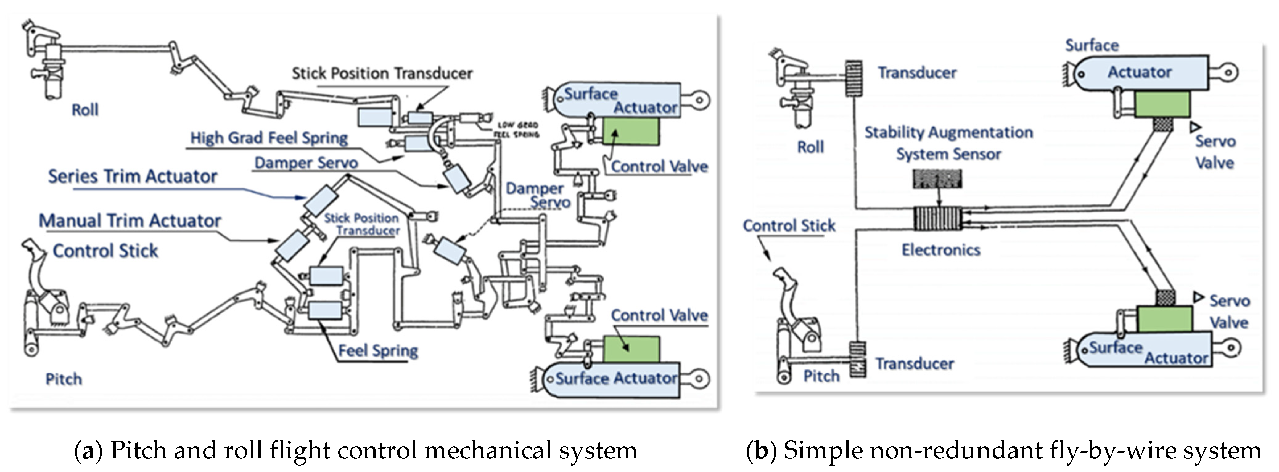
Figure 1. Flight control systems of a typical high-performance tactical fighter aircraft [13].
Aerospace 10 00787 g001
Figure 3. The EHSV and DDV actuator flow diagram of (Bae) EAP [29].
Aerospace 10 00787 g003
Figure 4. Block diagram of the B-2 bomber’s FCAS architecture [23,24].
Aerospace 10 00787 g004
Figure 5. Schematic of the Fairey DDV [30].
Aerospace 10 00787 g005
Figure 6. Schematic of architecture assembly that links the control surface and the airframe [31].
Aerospace 10 00787 g006
Figure 7. Parallel/Active mechanisms [32].
Aerospace 10 00787 g007
Figure 8. Block diagram of the EMA system of the C-141 left-hand aileron [45].
Aerospace 10 00787 g008
Figure 9. Matrix converter and electromechanical rudder actuator [54].
Aerospace 10 00787 g009
Figure 10. Top-level schematics of the ELGER and FDEAW systems [60].
Aerospace 10 00787 g010
Figure 11. The gimbal control system and the EMA system architecture [62,64].
Aerospace 10 00787 g011
Figure 12. Aviadvigatel PD-14 engine architecture [4,65].
Aerospace 10 00787 g012
Figure 13. System architecture of the fault-tolerant EMA [71].
Aerospace 10 00787 g013
Figure 14. Jam-tolerant electromechanical system [74].
Aerospace 10 00787 g014
Figure 15. Hydraulic and electric hybrid actuation systems [82]. (a) Hybrid force-summed actuation system architecture; (b) SHA position control/EMA position control; (c) SHA position control/EMA force control; (d) SHA position control/EMA no-load control.
Aerospace 10 00787 g015
Figure 16. Schematic of the control system of the test bench [83].
Aerospace 10 00787 g016
Figure 17. Redundant actuation system with adaptive control [87].
Aerospace 10 00787 g017
Figure 18. The four-lane torque-summed architecture [83].
Aerospace 10 00787 g018
Figure 19. Single-type torque-summed electromechanical actuation system [88].
Aerospace 10 00787 g019
Disclaimer/Publisher’s Note: The statements, opinions and data contained in all publications are solely those of the individual author(s) and contributor(s) and not of MDPI and/or the editor(s). MDPI and/or the editor(s) disclaim responsibility for any injury to people or property resulting from any ideas, methods, instructions or products referred to in the content.