Article

Parametric Processes for the Implementation of HBIM—Visual Programming Language for the Digitisation of the Index of Masonry Quality

ISPC Institute of Heritage Science, National Research Council, Via Salaria km 29,300, 00015 Montelibretti, RM, Italy
*
Author to whom correspondence should be addressed.
ISPRS Int. J. Geo-Inf. 2022, 11(2), 93; https://doi.org/10.3390/ijgi11020093
Submission received: 16 November 2021 / Revised: 12 January 2022 / Accepted: 25 January 2022 / Published: 27 January 2022
(This article belongs to the Special Issue Heritage Building Information Modeling: Theory and Applications)

Abstract

:
The heterogeneity and historical complexity of interventions on built heritage are testified by the constant development of the conservation discipline. The purpose of the research is the development of a digital workflow of parametric modelling for the analysis and conservation of historical buildings, by applying visual programming language (VPL) to support the Heritage Building Information Modelling (HBIM) methodology. VPL represents a tool for explicit parametric modelling that can be used to enhance geometric and information enrichment of HBIM models. The paper describes the integration, within an HBIM-VPL process, of the Index of Masonry Quality, widely used for seismic structural analysis, and its application to a case study in Cornillo Nuovo, a village damaged by the earthquake of Amatrice in 2016. Similar approaches could enhance HBIM modelling to support different knowledge domains associated with built heritage.

1. Introduction

The heterogeneity and historical complexity of interventions on built heritage are testified by the constant development of the conservation discipline, continuously acquiring new dimensions, such as the growing interconnection with social benefits, the fight against climate change [1,2], and advances in non-destructive testing [3] and structural diagnosis [4]. For this reason, the new discipline of “Heritage Science” is gaining traction, defined as “a very broad and transdisciplinary field that brings together the wide range of sciences (social, experimental, engineering, digital, humanities) that participate in and enable the identification, understanding, conservation, restoration and transmission of heritage” by the updated Strategic Research Agenda of JPICH [2]. This multidisciplinary effort of the study and analysis of cultural heritage needs the support of Information Technology to establish appropriate actions for documentation, conservation and valorisation by implementing integrated and interoperable tools to allow accessible and fast information exchange [5].
Within this framework, the current diffusion of 3D digital models for the documentation and conservation of built heritage [6] can be enhanced through a parametric approach. Parametric modelling involves the application of a pre-set series of interrelated rules (algorithms), which introduce formal and dimensional constraints and data (parameters), whose manipulation allows for the controlled variation of the models [7]. When modelling historical architecture, this parametric approach is aimed at combining variable constraints and measures to enhance the geometrical representation [8,9] of building elements, and also at extending the boundaries of such models by integrating alphanumerical information [10].

1.1. Parametric Modelling

We can identify three types of parametric modelling, depending on the usability of tools and the computer knowledge required of the user:
  • level 1: parametric modelling through a simplified interface;
  • level 2: parametric modelling via a textual programming language;
  • level 3: parametric modelling via a visual programming language.
Level 1 involves the use of specific modelling software equipped with a graphical user interface (GUI) expressly designed to guide the user in the construction of building elements generated through preset parameters. This type of parametric modelling requires a low level of computer knowledge [11].
Within level 2, the user employs textual programming language (TPL) to write executable programs, following the rules of the chosen language (C#, Python, VBScript, etc.), to perform a given task and obtain a geometric model output. This type of parametric modelling requires a high level of computer knowledge [11].
Level 3 applies visual programming language (VPL), composed of graphic nodes, that is more accessible than TPL for professionals (such as architects, engineers, etc.) familiar with visual design and modelling, but is limited in the full access to the potential of the software used. This type of parametric modelling requires a medium level of computer knowledge [12].
Since the 1950s, the digitisation of the building sector has marked the progressive employment of level 1 parametric software for architecture models [13], for instance, computer-aided design (CAD) and, more recently, building information modelling (BIM), based on the construction and updating of a shared 3D digital representation of a built asset that combines geometric, alphanumeric and document information [14,15]. Given that BIM offers a framework to organise both geometric and non-geometric data in a spatial hierarchy, thus providing a centralised hub for all information related to a building [16,17], the application of BIM processes to built heritage, known as Heritage BIM (HBIM), is growing to support documentation, conservation, management, design and maintenance activities on historical buildings, ensuring the permanence, accessibility and implementation of data [9,18,19].
The first decade of the 21st century witnessed the spread of the level 3 parametric approach through the use of visual programming languages (VPL) for solving complex problems in architecture [7,20].
Parametric modelling via VPL is also supported, within several software solutions, by specific programming libraries dedicated to architectural modelling, boosting the interoperability between different tools for the building sector. TPL use, when allowed by software, could be even more effective in the customisation of processes; however, its widespread application is hindered because the level of computer knowledge required is not yet part of the basic training of AEC (architecture, engineering, construction) professionals [21].
The possibility of programming languages to reveal that the algorithm structure behind a given parametric process enables a further classification: implicit parametric modelling and explicit parametric modelling. Within implicit parametric modelling, the focus is on the resulting model in a digital environment [22]; parametric processes are managed through pre-set interfaces that are able to modify the geometry and information of the model objects via numerical and data constraints [23]. Parameters are also used to enrich objects with information properties from different knowledge domains, in order to place the overall model in a larger information context. The possibility to visualise model objects in 3D and 2D views and to modify their properties inside property windows, activated by object selection, greatly simplifies information enrichment: therefore, the modeller can concentrate on representing model objects in the required level of geometry and information detail [13].
Explicit parametric modelling directs the focus not only to the final result (the model) but also to the procedures that generated it. These explicit (i.e., visible) procedures connect parameters and relational constraints to constitute an open and modifiable code. The prototypical nature of this process provides a suitable research environment, where the investigation also involves continuous interactions with the programming language, resulting in immediate feedback in the model.
In this context, VPL represents a valid tool for explicit parametric modelling, as it is based on a flowchart system, which fixes the algorithmic process in a visual script of nodes and connections that explicitly narrates the construction history of the entire parametric process (Figure 4). The ability to establish efficient relationships between data and geometry within a model is one of the greatest potentials of explicit parametric modelling.
The current research investigates the relationship of parametric modelling systems in BIM processes (implicit parametric modelling) with visual programming language (explicit parametric modelling), aimed at extending the boundaries of BIM for modelling historic architecture (HBIM). To this end, the concept of VPL will be briefly outlined, highlighting its potential and limitations. An example of an innovative workflow for the digitalisation of the Index of Masonry Quality [24] will illustrate the potential of the synergy between BIM and VPL to improve the information management of built heritage.

1.2. VPL as a Language for Writing Digital Processes

In the 1970s at Stanford University, David Canfield Smith experimented with a programming language whose syntax was not textual but iconographic, and his doctoral thesis investigated both visual content and the link between graphic design and computer programming [25].
The reaction times between graphic action and programmed reaction were initially not efficient, due to the limited hardware resources available, so there were strong limitations related to instruction execution times, overcome in the 1990s with the advancement of processors [26,27]. The last twenty years have consolidated VPL as a widely-used programming language [7].
The commonly used definition for describing a VPL system is as follows: “In computing, a visual programming language (VPL) is any programming language that lets users create programs by manipulating program elements graphically rather than by specifying them textually. A VPL allows programming with visual expressions, spatial arrangements of text and graphic symbols, used either as elements of syntax or secondary notation” [28].
As shown in Figure 4, the most widespread visual languages are based on user-friendly graphical interfaces, to ‘write’ the process using simple graphic geometries: rectangles (nodes) and oriented curves (connections). The nodes identify clusters (The minimum portion of code used by software to perform an action. The portion is nested in a single node with input and output.) of input and output that collect, process and send information; the data flow is organised using connections represented by one-dimensional entities (arrows, lines, arcs, etc.) [29]. VPL is currently employed in many areas of the digital domain: educational, multimedia, video games, automation, 3D modelling, etc. VPL environments can be part of specialised software (e.g., a 3D modelling software, rendering software, etc.) to access and implement its native resources and tools (e.g., points, curves, surfaces and transformations), or they can be autonomous environments providing an easier interface for general-purpose programming, for example in the education field [30].
The benefits of VPL can be assessed by considering the characteristics that distinguish all languages: syntax, semantics and pragmatics [31], and also adding the characteristic of implementation:
  • Syntax—VPL has a simplified syntax since the relationships between signs (nodes) are delegated to simple oriented one-dimensional connections (curves) that control the flow of information in and out of the nodes.
  • Semantics—VPL allows semantic disambiguation, thanks to metadata information on nodes. In general, each graphical component is enriched with information or links to documentation that explain how the component works.
  • Pragmatics—Each graphic node in the language is an action within the program: thus, there is a direct relationship between the language and its results. Several connected nodes activate a series of computational elements that influence the efficiency of the relationship between action (performed by the programmer) and reaction (response of the device being programmed).
  • Implementation—Programming languages should be easily modified, also over time, respecting the semantic rules; this condition allows for the pragmatic enrichment of the language and enhances creativity in the algorithm.
The direct correspondence between VPL and flowcharts boosts the rapid learning of the syntax; nonetheless, this extreme schematisation often results in the early obsolescence of codes. The limited number of signs available to a VPL imposes a continuous implementation of the nodes, making the oldest codes not executable by the most recent versions of visual programming platforms. The presence of a strong semantic framework, with tools for the annotation of in-progress codes, is useful, because it facilitates the reading and writing of the code by different users and in different time phases.
The development of new components is common in the architectural field [32], where VPL systems are often associated with generic modelling software (CAD) or specific software for architecture (BIM). These software solutions manage digital procedures within the knowledge domains involved in the construction sector. When it is necessary to integrate information from different disciplines, it is often possible (depending on the software) to develop additional thematic nodes by third parts within the VPL syntax, thus enabling the interoperability with other specialised external software (e.g., software for structural analysis, energy simulation, GIS, etc.). VPL interface, while sophisticated and highly accessible, does not have the tools to compile an independent software application, being confined to the support of other software or a prototype phase.
The connection between different digital environments requires the additional nodes to remap and feed the information coming from the main VPL code as inputs for external software. Two main data processes support this connection (Figure 1):
  • a biunivocal process, where the results (outputs) of the operations in the external software, appropriately remapped, are then fed back into the main code as new inputs, providing specialised information. The process is responsive: a change in the information flow of the main code affects the inputs, and subsequently the outputs, of the external software, which are automatically updated and remapped. The scheme is equally valid if the information is processed not by external software but by add-ons that extend the computational capabilities of the main programming platform;
  • a univocal process, where the results of the operations of the external software are not fed back into the main code; this generally involves the compilation in VPL of files compatible with the external platforms. This process hinders the responsive control of the main code over the external information flow.
In both processes, one of the main challenges is the correct mapping of information, from output of the main code to input of the external software, and vice versa, because data structure must be rearranged according to the specific rules of the digital environments involved. This process of solving data compatibility issues is known as “shimming” [33] and can lead to cluttered workflows that can become hard to reuse [34]. On the VPL end, this connection, although extremely productive, increases the proliferation of additional components and, in some cases, leads to the redundancy of repeated parts, making the visual scheme less readable and efficient.

1.3. HBIM as a Methodology for Information Management of Built Heritage

Within building information modelling (BIM), a building is modelled as an assembly of components [21], each represented by a digital equivalent (object), whose parameters allow to manipulate its 3D geometrical representation, its associated data properties (in the form of key-value pairs, i.e., the name of the property and the corresponding content) and the rules and relationships with other objects [13]. While in traditional 3D CAD an element’s geometry must be manually edited by the users, in a parametric modeller the shape and characteristics of elements can be changed by modifying the corresponding parameters (e.g., changing the length or width of a window by modifying its numeric dimensions), or they can automatically adjust to changes in relative elements (e.g., the position of a window automatically changes if the corresponding wall is moved) [16,18].
Depending on the BIM authoring software used, each object (instance) in the model is defined within a hierarchy of levels (classes), i.e., a set of relations and rules to control the parameters about geometry, identity, appearance, performance and usage by which the instances can be generated and modified according to their context. Information at each level is shared by the levels below. The higher level (generally called category) represents a group of components sharing a technical function, form and/or position (e.g., walls, windows, roofs), with specific properties applied to the whole group. Sub-groups of components (generally called family and/or types) can specify common values for some properties, corresponding to common characteristics (e.g., roofs with a given thickness or layer stratigraphy). The hierarchy also sets which parameters can vary at the instance level, by changing the values attributed to instance properties [35].
Some of the parameters within the hierarchy depend on user-defined values; others depend on fixed values and others are taken from or are relative to other objects. This data system is dynamically updated according to changes in the hierarchy of objects or their relationships [16]; the way each instance changes depending on modifications of its context is called its “behaviour”.
This type of rigorous structure, optimised for the current building sectors, presents some drawbacks when applied to historical buildings, following the HBIM approach [18]. For instance, to exemplify the most common characteristics and interactions among building components, typical of industrialised construction systems, fixed categories and parameters and a set of predefined behavioural rules are applied to all levels of the hierarchy: for example, floors are automatically connected to walls to represent their structural bond. These pre-sets are an essential simplification that works well with typified cases but often does not fit with more complex, non-standardised buildings and components common within the built heritage. On the other hand, parametric modelling of BIM can support the custom creation of historic architectural elements, that are usually unique to a building but are often subject to a grammar of shape and specific construction techniques, depending on the historical period, location, architectural style, whose representation and analysis can be enhanced by a structured hierarchy of parameters, rules and relationships [36]. Parameters can also simplify the integration and coordination of multidisciplinary information from different knowledge domains [37]. Nonetheless, current BIM procedures are not always suitable to correctly convey the formal and technical complexity and information heterogeneity of historic buildings [38]. For instance, typical elements of built heritage, such as vaults, are generally not part of built-in categories, or else the predefined rules of such categories exclude certain aspects common to historic components, such as the representation of out-of-plumbs walls or decay patterns and cracks. Workarounds and special modelling strategies can help solve specific issues, but often result in the reduced parametric behaviour of the objects: for example, out-of-plumbs walls can be modelled as ad-hoc elements, but the representation of stratigraphy and the export to open formats is strongly reduced [39].

2. VPL for HBIM Process Integration

The connection between VPL and BIM allows for overcoming some rigidity of the latter in the representation of historical buildings, maximising the use of a parametric approach. There are several procedures and areas of intervention in which this connection can be adopted; in this section, we will mainly focus on the solution of two issues:
  • the geometric modelling of complex shapes typical of built heritage (e.g., vaults) in the BIM environment;
  • the gathering, manipulation and collection of information in the BIM environment, especially information from different disciplinary fields related to historical buildings.
The current research presents a case study on the implementation of the calculation of the Index of Masonry Quality (IQM) [40] for a historic building in the BIM environment.

2.1. Implementation of Geometries and Information in an HBIM Environment

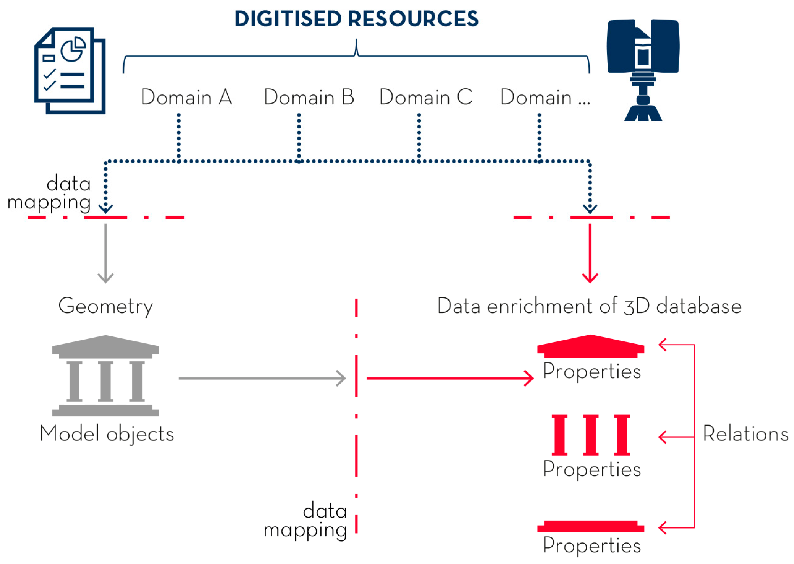
Nowadays, the implementation of complex shapes within parametric software for architectural modelling can benefit from numerous VPL applications, capable of creating a bridge between CAD and BIM resources (for example, McNeel, the software house of Rhinoceros (CAD software) and Grasshopper (visual programming language), supports the development of applications that connect the CAD resources of Rhinoceros to Archicad (Graphisoft BIM software) and Revit (Autodesk BIM software). Respectively for Archicad we have the Grasshopper—Archicad Live Connection plug-in (https://graphisoft.com/downloads/addons/interoperability/rhino, access date: 15 November 2021), for Revit we have Rhino.Inside.Revit (https://www.rhino3d.com/inside/revit/1.0/, access date: 15 November 2021), the latter being the technology used in our work), thus enhancing the geometric modelling and information enrichment of complex architectural elements. It is therefore possible to outline a general workflow to develop a parametric model based on digitised information from different knowledge domains, thus supporting the dialogue between built heritage experts (Figure 2). The external resources are inherently non-homogeneous (raster, point clouds, spreadsheets, etc.) and support morphological, historical, philological, static, physical, diagnostic information and so on. Through programmed procedures, data are ordered and channelled towards parallel and synergic processes that are able, on the one hand, to describe and develop geometric shapes, and, on the other hand, to generate the information for enriching the shapes themselves. Therefore, the initial components of the VPL code create a link to the digitised ‘raw’ information that is then remapped by a series of other components to flow the data towards the appropriate processes (data flow management).
The diagram in Figure 2 shows these two parallel processes. On the left, the filtered data defines the geometries of new shapes: the code for the construction of these shapes established several numerical and textual parameters to flexibly adapt to different dimensions and constraints. The parameters allow a constant control of the results, determining the responsiveness of the model that changes in relation to the variance (and accuracy) of the input data.
The process on the right employs part of the same data to define the information to enrich the geometric shapes. Other components associate these shapes with the corresponding architectural categories (vaults, windows, decorative elements, etc.) and hierarchy levels (families and types), if any, and the corresponding information; all together they will contribute to the composition of an original multidisciplinary 3D database capable of describing in-depth the cultural artefact when queried.

2.2. Management of External Data in an HBIM Environment

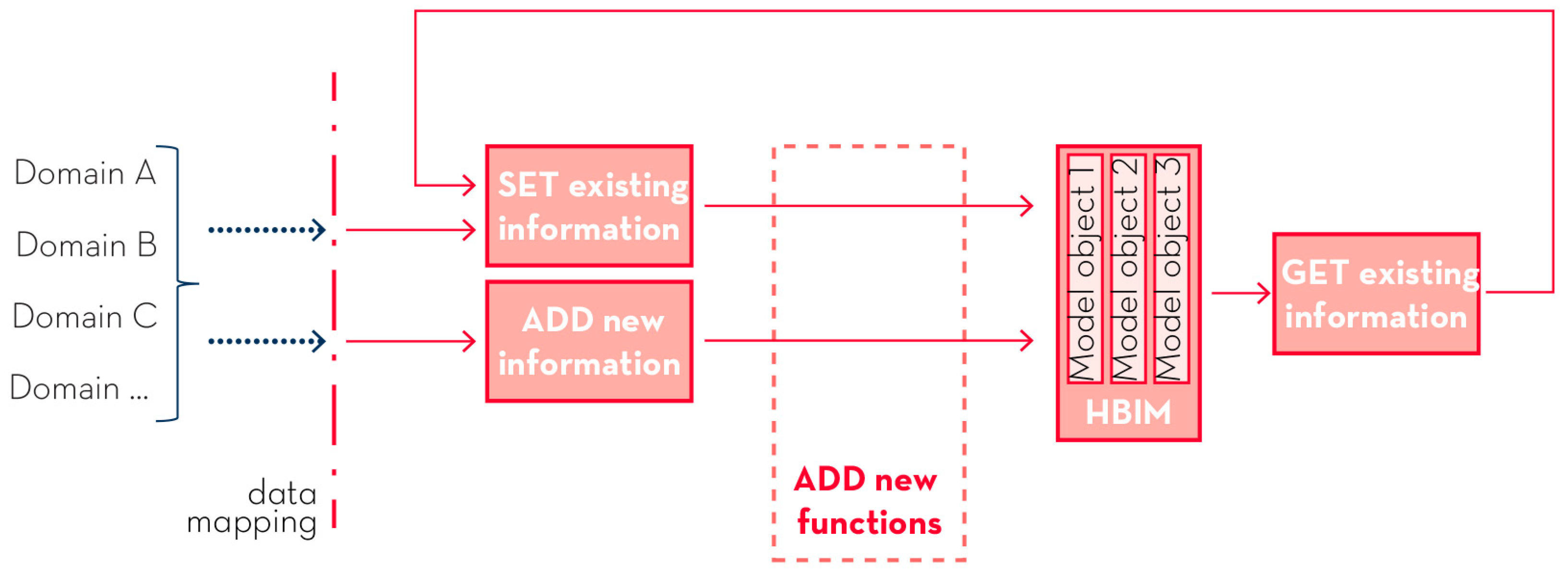
The diagram in Figure 3 specifically details the algorithmic structure to manipulate and collect information from different disciplines in the BIM environment. This part of the process aims at the implementation of new information and the definition of mathematical operations in the BIM environment to address some information gaps and software issues in the management of historical buildings. This process is based on two principles: filling existing properties with new information and adding new properties to contain new information.
Regarding the definition of mathematical operations among properties, the aim is to program original relations in VPL with which to associate the different object properties (whether existing or new), providing analytical qualities not foreseen by the majority of BIM software, but paramount to describing additional characteristics with which to describe the model in the HBIM environment. Depending on the software used, this model enrichment with information from various knowledge domains can occur at different levels of the object hierarchy, e.g., category, family, type and instance.

3. Methods: VPL Digitisation of the Index of Masonry Quality in HBIM

As an example of how to capitalise on the use of VPL in an HBIM workflow, the current research presents a method to digitalise the Index of Masonry Quality (IQM) in HBIM. Despite the advancements in diagnostic techniques, the evaluation of the current structural condition of built heritage remains a challenging task, mainly due to the large number of uncertainties related to the geometry of structures, the interactions between non-homogeneous parts and the mechanical, chemical and physical differences of materials [4]. While the needed level of detail and accuracy for specific in-depth analysis is often economically unfeasible and time-consuming, low-cost and quick analysis procedures are increasingly being applied to large portions of historic urban settlements to enhance prevention and conservation actions [41]. For example, the IQM allows experts to evaluate, for masonry structures, the presence (both complete and partial) or the absence of specific parameters that define its workmanlike manufacture (“regola d’arte”), its compactness and monolithicity. The calculation of IQM is differentiated for vertical actions, horizontal actions and orthogonal actions to the median plane of the masonry wall, respectively IQMV, IQMFP, IQMNP. For stone masonry, IQM values are calculated according to the following functions:
IQMV = m × REELV × (ORV + PDV + FELV + SGV + DELV + MAV),
IQMFP = m × REELFP × (ORFP + PDFP +FELFP +SGFP + DELFP + MAFP),
IQMNP = m × REELNP × (ORNP + PDNP + FELNP+SGNP + DELNP + MANP).
For solid brick masonry, the corrective values r and g are introduced:
IQMV = m × g × rV × REELLV × (ORV + PDV +FELV +SGV +DELV +MAV),
IQMFP = m × g × rFP × REELFP × (ORFP +PDFP +FELFP +SGFP +DELFP +MAFP),
IQMNP = m × g × rNP × REELNP × (ORNP +PDNP +FELNP +SGNP +DELNP + MANP).
Each parameter represents a numerical value corresponding to the visual assessment of a given masonry wall. For instance: MA corresponds to the good quality of mortar/effective contact between elements; PD to the transverse joint/presence of diatons; FEL to the square-shaped load-bearing elements; DEL to the load-bearing elements of large size compared to wall thickness; SG to the offset between vertical joints; OR to the presence of horizontal stretcher bonds; REEL to the good quality of the load-bearing elements; m to the poor quality mortar; g to the presence of wide joints for solid brick or block masonry; and r to a corrective factor for brick masonry.
The results of the functions assign the analysed wall to one of the three IQM categories (A, B and C) of masonry quality, from best to worst (for a detailed definition of the method, please refer to [24,40]).
Although it is possible to partially integrate natively the calculation of the IQM in the most common BIM software, it was decided to use the VPL to overcome some software rigidities related to the manipulation and calculation of parameter values. In addition, the VPL allows the creation of an original workflow, with the broader aim of investigating and proposing new digitised protocols for the scientific community. The experimentation of the process was carried out with parametric CAD and BIM software, popular within the architectural field, that allow the integration of operations through VPL: for instance, Autodesk Revit for BIM modelling, Grasshopper by McNeel as the interface for the VPL and Rhino.Inside.Revit add-on to manipulate Revit with Grasshopper. The IQM implementation procedure involves the definition of a Revit template that guides the user to fill in the new required parameters (frontend actions), provides a visual and textual representation of results, and develops a code for the digitisation of the IQM calculation functions (backend actions).

3.1. Digital Implementation of IQM in Revit: Adding New Instance Parameters

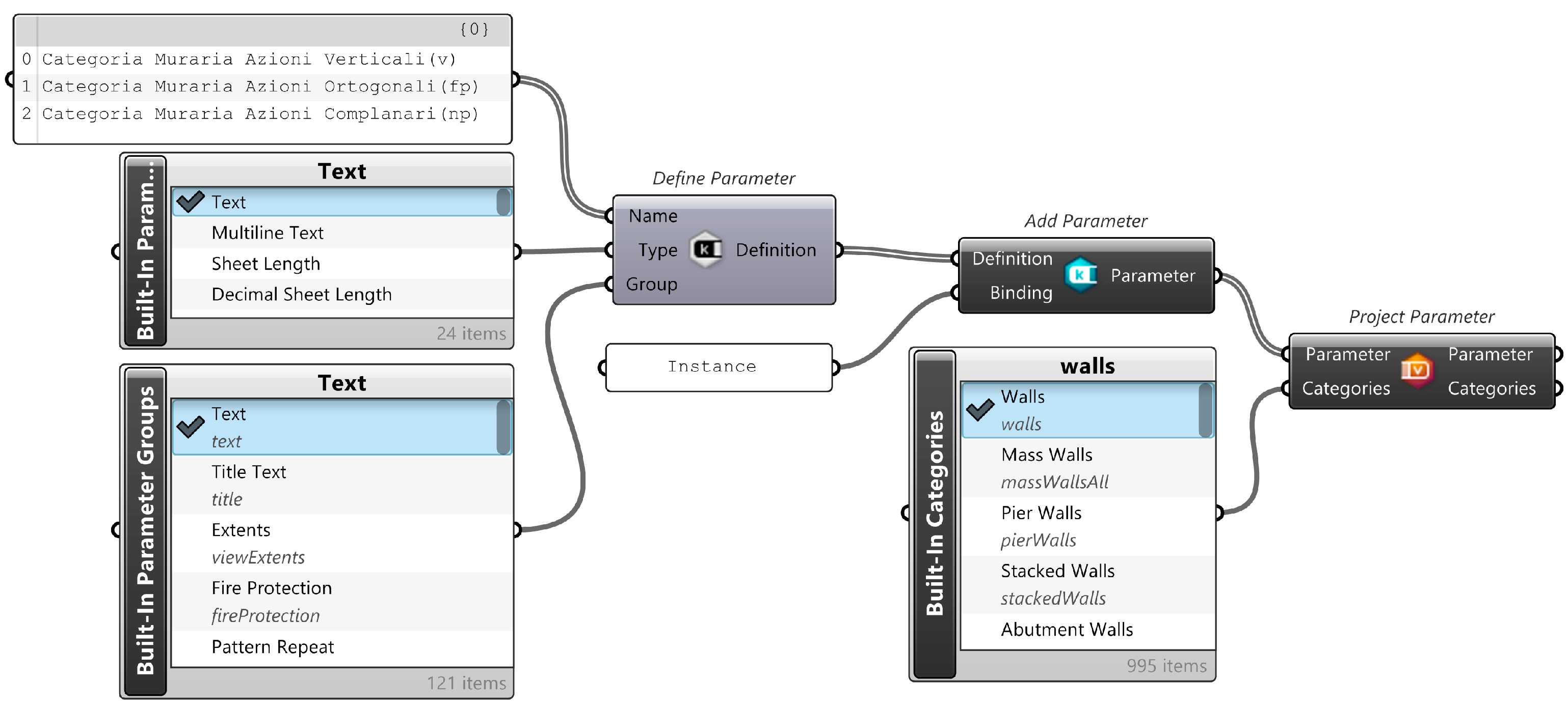
In VPL (Grasshopper), we define a Revit template that adds new properties to wall instances for the masonry categories (the IQM parameters) and also new calculation functions (Figure 4). Starting from the values introduced in new properties (input), said functions automatically return the masonry quality class (IQM categories) as the value of additional properties (output) through the standard labelling (A, B, C). The walls included in the IQM analysis are also automatically coloured with the standard colours (green, yellow and red for the walls of category A, B, and C, respectively) in special 3D views.
The components suitable for connecting Grasshopper to Revit are mainly provided by the Rhino.Inside.Revit application. The Define Parameter node requires as input the names of the new added properties, or key (name), which refer to the parameters of the IQM: OR_Presenza filari orizzontali, PD_Presenza di diatoni, FEL_Forma degli elementi resistenti, SG_Sfalsamento dei giunti verticali, DEL_Dimensione degli elementi resistenti, MA_Qualità della malta, REEL_Resistenza degli elementi, r_Tipologia Muraria (The Italian names of the parameters correspond to, respectively: OR_presence of horizontal stretcher bonds, PD_/presence of diatons, FEL_shape of load-bearing elements, SG_offset between vertical joints, DEL_dimensions of load-bearing elements, MA_quality of mortar, REEL_elements resistance; and r_wall typology.), with the last one referring to the typology of masonry, stone or solid bricks. The value of these properties is always a textual string, a characteristic defined through the Type input. Finally, to arrange these properties within the instance properties of walls, the group to which the new information belongs is defined as Identity Data. The properties are added to the Revit template through the Add Parameter component, specifying to which category of model objects they refer to, in this case, the wall category, using the consecutive Project Parameter component.
The definition described above allows new input strings to be inserted into the model, which will subsequently be compiled by an operator, following the analytical observation and graphic evaluation of the walls’ surfaces (parametro rispettato, parametro parzialmente rispettato, parametro non rispettato, i.e., non-compliance, partial compliance or compliance with the parameter, respectively). With the same method, the properties of the IQM in the three directions of the wall plane, automatically obtained as a result of the IQM calculations (see Section 3), are also added to the wall instance properties window (Figure 5).

3.2. Digital Implementation of IQM in Revit: Adding New Functions

The digitisation of the IQM, in addition to adding new parameters to the instances that constitute the architectural model, suggests the use of functions (IQMV, IQMFP, IQMNP) that return data for further enrichment of the architectural elements analysed. These new parameters also help to fill the information gaps that BIM modellers have in the description of cultural heritage. The functions to calculate the IQM are added in Revit with Grasshopper and Rhino.Inside.Revit, according to the IQM method [40].
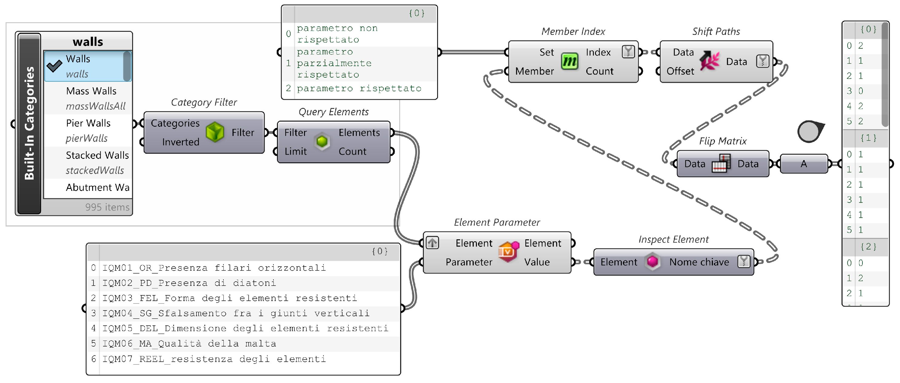
The first three components (Built-in Categories, Category Filter, Query Elements) of the code in Figure 6 are used to insert all the walls within the model into a list. Element Parameter reads the values written in the previously created properties (OR, PD, FEL, SG, DEL, MA, REEL). The output data are a sequence of characters that combine the property values with other information, such as the ID of each wall object; Inspect Element allows the property values to be isolated from unnecessary information. The Member Index component associates, for procedural convenience, a number to the textual information (parametro non rispettato = 0, parametro parzialmente rispettato = 1, parametro rispettato = 2); finally, Shift Paths and Flip Matrix orders the data in a sequence of nested lists where each list is related to a single parameter (OR, PD, FEL, SG, DEL, MA, REEL), listing within each of them the list of textual values numerically remapped wall by wall.
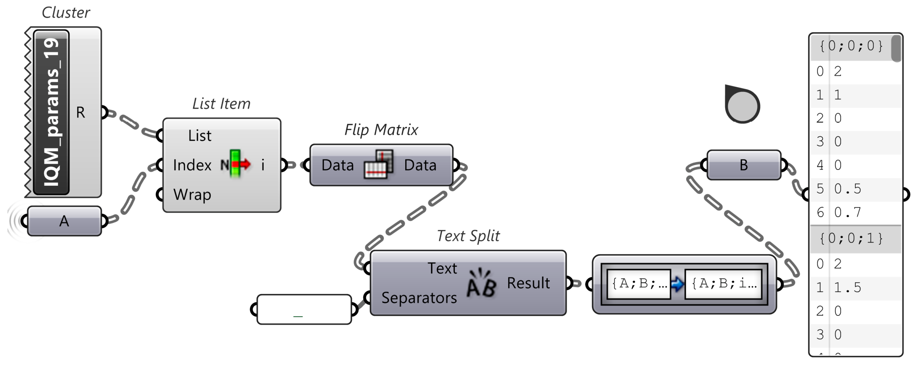
Subsequently, the scores to be attributed to the parameters of the “regola d’arte” for the calculation of IQMV, IQMFP e IQMN are introduced into the calculation, considering the requirements of the Italian regulation on structural analyses of built heritage (Circolare No. 7/2019 [40]). The table is nested within the cluster IQM_params_19 and the list item component extracts the values for non-compliance (0), partial compliance (1) or compliance (2) with the parameters set by the IQM calculation for the analysed walls. The table is defined as a cluster to allow for an easy update of the code in view of future developments of the legislation by simply changing one component. The next three components (Flip Matrix, Text Split, Path Mapper) allow the cluster structure to be transformed into a nested list for simulating the matrix of values extracted for each wall (Figure 7).
The next part of the code is focused on writing the functions for calculating the IQM (IQMV, IQMFP, IQMNP) for all the analysed walls. The calculation differs according to the typology of walls (stone or solid brick). Figure 8 (below) depicts the portion of code that reads the values related to the typology of each wall instance (identified by ID), with the Element Parameter component; the Member Index that remaps the textual values into numbers that are listed in a single list with the Shift Paths and Flatten Tree components. Similarly, the parameters m and g (mortar quality and joint width) are read and written.
The seven parameters relative to each wall and expressed for the three solicitations in the three directions of the wall plane (V, FP, NP), deriving from the input properties set at the beginning of the process, flow into the portion of code for calculation. The code is set up in parallel with the calculation of the two typological conditions of the wall, stone and solid brick (Figure 9), selecting only at the end of the process the value that corresponds to the type of instance modelled. Both calculation branches involve summing up six of the seven parameters (REEL is excluded) using the following components: Cull Index to exclude the REEL parameter, Mass Addition for the sum of the remaining six parameters and Shift Paths to structure the data to be combined with the other sections of the calculation code.
In the function, the REEL parameter is one of the factors of the product isolated from the list of parameters using the List Item component which, for each wall, picks out the REELV, REELFP, REELNP parameter; Shift Paths organises the structure of the data to match the rest of the calculation. The next step is the actual calculation, using the Expression components to write the functions relative to the two different wall types (see Section 3). At the end of the calculation, the three IQM category values are obtained for each wall, taking into account both possible typologies of the wall; for coding convenience, the three values are joined in a single text string with the Text Join component. This facilitates the role of the next component, Pick’n’Choose, which, depending on wall typology, will select the correct calculation value. Text Split and Flip Matrix remap the data into numbers that can subsequently be compared with the numerical ranges defined by Circolare No. 7/2019 [40] for the extrapolation of the IQM standard labelling (A, B and C).
The last part of the code is dedicated to writing the IQM category output as textual values within the instance properties created, as described in Section 3.1. The Categorie_19 and Consecutive Domains components replicate the numerical ranges in VPL; the three IQM values are then compared with the tabulated parameters using the Cross Reference and Includes components. The subsequent components, Cull Pattern and Shift Paths allow numerical values to be replaced by textual evaluations. Flip Matrix remaps the data to be inserted in the strings Categoria Muraria Azioni Verticali (v), Categoria Muraria Azioni Ortogonali (fp), Categoria Muraria Azioni Complanari (np) used by the Element Parameter component to fill in the properties of the corresponding wall instances (Figure 10).

4. Results: Workflow for IQM Enrichment in an HBIM Model

The procedure described above sets up a specific IQM Revit template file that can be used by IQM operators, even with little or no experience with VPL, in an overall workflow of IQM digitalisation in an HBIM environment. The template file presents pre-set features to support the evaluation of IQM within HBIM; the use of VPL, integrated in backend in the template, automate all the calculations, speeding up the process and reducing the possibility for error, thus allowing the operators to be able to concentrate instead on the technical analysis and evaluation of masonry.
The digitalisation of IQM in HBIM, based on the use of the IQM Revit template, is a broader workflow, influenced by the type of building, data collection, available diagnostics, etc. In general, it encompasses several phases, typical of HBIM modelling procedures [17,18], with specific characteristics depending on the IQM calculation (Figure 11):
  • photogrammetric survey of the analysed building;
  • point cloud definition from photogrammetry (optional);
  • HBIM modelling from the survey (within the IQM Revit template);
  • critical evaluation of the compliance of the seven IQM parameters, capitalising on the VPL automation to obtain the corresponding IQM results.

Application of the Workflow to the Case Study of Cornillo Nuovo

To validate this workflow and the specific use of VPL to IQM calculation, it was applied to research [41] on vernacular built heritage, which comprises a relevant portion of the built-up area in Italy, with a notable seismic risk [42], and is often characterised by relative structural simplicity, a modest quality of materials and construction elements, a lack or poverty of maintenance, and temporal or permanent abandonment. Low-cost, quick, effective analyses to assess buildings conditions, such as the digitalisation of IQM in HBIM, are paramount to enhance prevention and protection activities.
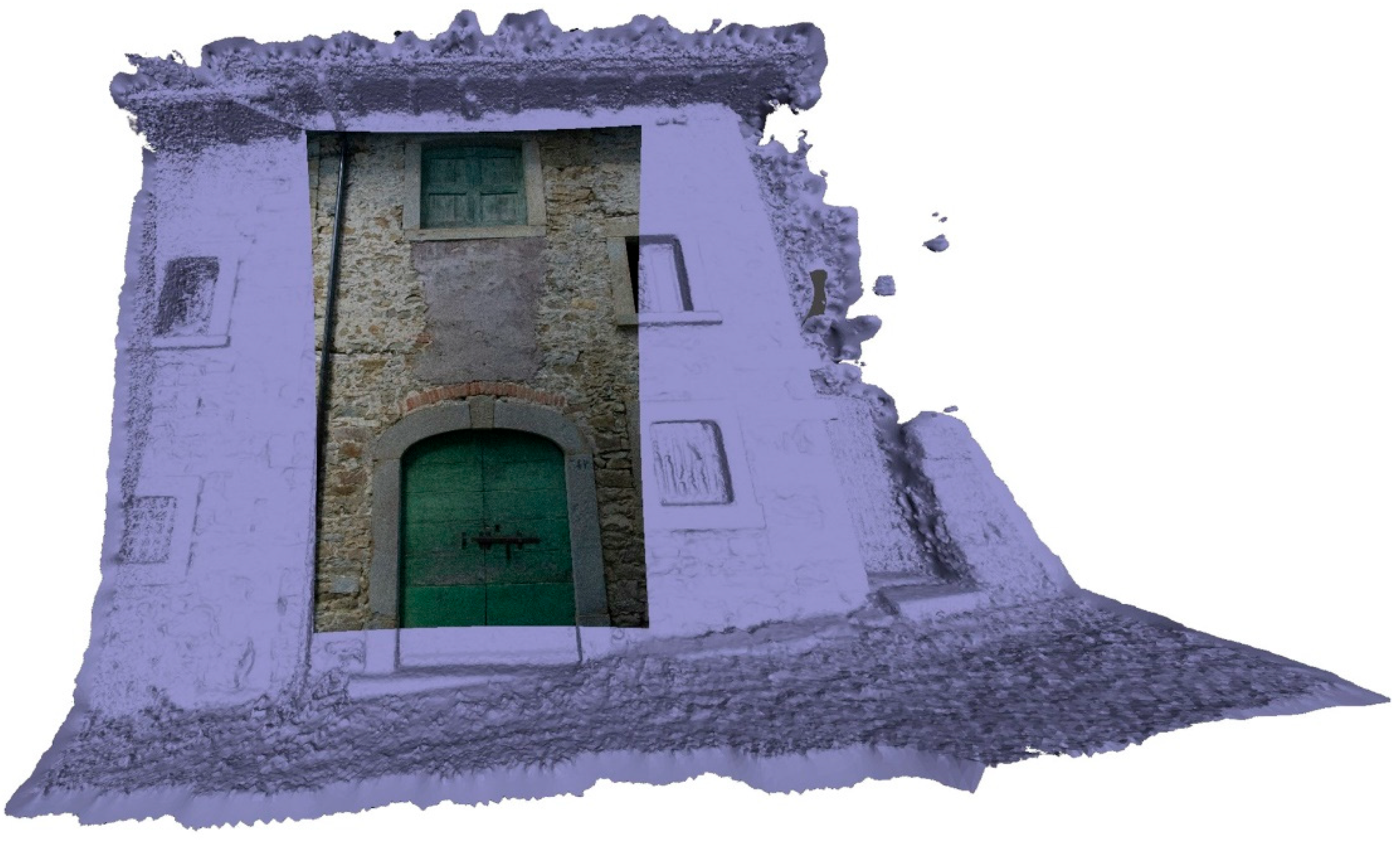
The research concentrated on a building in Cornillo Nuovo (Figure 12), in the area of Amatrice, a region severely damaged by the 2016 earthquake [43]. The building, still intact, is a typical example of the Amatrician masonry: irregular coursed rubble wall, the re-use of sandstone blocks reddened by fire, brick fragments and yellow ochre mortar with low lime content and poor mechanical quality.
The evaluation of masonry for the digitalisation of IQM in HBIM required a detailed photographic survey of the building in Cornillo Nuovo (Figure 12). Digital photogrammetry is considered the appropriate technique to integrate both a high resolution and colour quality of the dataset and a point-cloud 3D representation for HBIM modelling, with a limited cost and time effort compared to other survey techniques such as laser-scanner [44]. A Canon EOS 750 D camera was used; shooting in converging blocks with approximately 30% coverage between frames. Moreover, the precarious state of the adjacent buildings allowed better observation of masonry sections, their construction techniques and the quality of components.
A Structure from Motion process [45] produced a 3D textured point cloud from the digital photogrammetry, which distinctly conveys the exterior features of wall surfaces and identifies the outlines of different masonry typologies. The point cloud was then imported in the IQM Revit template to support HBIM modelling, while two-dimensional views (elevations) of each facade could be used for the remote graphic assessment of the IQM parameters. This assessment is undertaken manually, following the IQM method, on a detail view of a homogeneous 1 m × 1 m portion of masonry, by 2D drawing and measuring the masonry features directly on the 3D textured point cloud, and it is comparable to the standard procedure that is generally undertaken on photographs or via CAD 2D software. However, the possibility to perform such assessment directly in Revit establishes a centralised information hub for the whole process.
The building was segmented into building components and constructive systems [14] to be modelled (Figure 13) via a Scan-to-BIM procedure, in which the imported point cloud is used as a “scaffold” to manually model and place BIM objects corresponding to the defined building components [18]. For the segmentation of wall components, the Level of Information Need of the HBIM model (i.e., the requirements for geometry, documentation and information detail) [15] must support the IQM evaluation, therefore it was paramount to model each identified section of masonry as a separate BIM object, to accommodate the corresponding values of IQM parameters. The other building components, following the constructive approach promoted by IQM analysis, were segmented into: roof and floor construction (structural frame of principal and secondary beams, decks and slabs); windows; doors; and plumbing. Special care was taken to depict materials and junctions. Windows and doors are parametric objects and have been modelled in detail to represent their structural and decorative features (stone portals, brick discharging arches); they can be reused and adapted to model the other buildings of the same typology in the area, with few changes in their parameters. If needed, the HBIM model can be integrated with other investigations and interventions on the building.
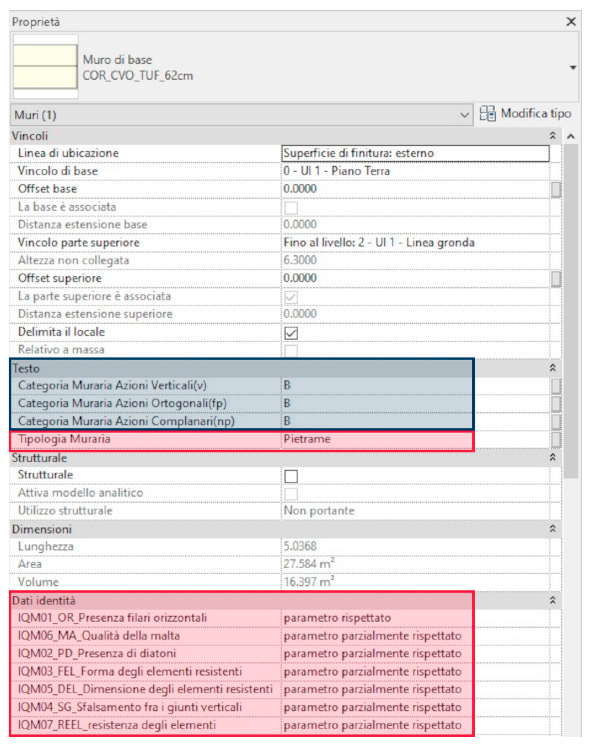
Within the IQM Revit template, when the HBIM model and the graphic assessment of IQM parameters was concluded, the IQM operator filled in, for each wall, the corresponding typology of masonry (stone or solid brick), the HBIM properties of the IQM parameters (OR, PD, FEL, SG, DEL, MA, REL) and the corrective coefficients (r, m, g) for calculating the IQM [40]. Thereafter, the connection between BIM and VPL automatically acquired the IQM parameters as input, performed the required IQM calculation and returned the output values of IQMV, IQMFP, IQMNP (A, B, C) for each wall, filling in the additional pre-set HBIM properties of the template (Figure 14).
The template also introduced a ruled-based filter of graphic visibility in specific 3D views of the BIM model (Figure 15), based on the output values of IQM, which automatically coloured in green the walls of category A, in yellow those of category B, and in red those of category C.

5. Discussion

The paper presents an example of a sharing prototype process, whose objective is the testing of visual programming language to enhance heritage BIM processes, exemplified by the digital transposition of an operation (the Index of Masonry Quality calculation) generally carried out partly or totally analogically. There is ample room for the development of this type of research applied to several domains of knowledge; for instance, the integration of specific analysis reports of single experts within a comprehensive information platform on a given historical building. In addition to hyper metadata of the model, the superimposition, or better, the amalgamation, of new informative levels can lead to innovative hypotheses of management and diagnosis of built heritage. The work of digitising the IQM in HBIM is exemplary of a so-called “digital implementation process”, since a first version [43] in which the analogic operations were “rewritten” using a parametric level 1 process (BIM) which, despite its computational efficiency, nevertheless presented limitations due to interoperability problems internal to the BIM software used. These limitations led to the development of the version explained in detail in the current paper, written completely with level 2 parametric processes using VPL.
As described at the end of Section 1.2, VPL also has drawbacks, often due to the updating of components, that leads to the obsolescence of the automated processes, which must be periodically updated, often with the last software version. Conversely, within an explicit and “readable” process, it is easy to identify outdated nodes and update them without having to completely rewrite the code: an example in the current research is the design of cluster components of legislative information, to be simply updated if current regulation changes.
Therefore, future development of the research could involve the publication, for sharing purposes, of the different code versions of the digitised processes in open access web portals accessible by the scientific community and professionals, following the FAIR (https://www.force11.org/fairprinciples, access date: 15 November 2021) principles. Together with the growing awareness of VPL and BIM in the AEC sector, this publication will allow the replicability and implementation of the process to become a general research tool. Subsequent development of the process through parametric level 3 languages (TPL) could turn it into a product measured according to a progressive Technology Readiness Level (TRL) (https://www.nasa.gov/directorates/heo/scan/engineering/technology/technology_readiness_level, access date: 15 November 2021).
Regarding the IQM digitisation, the use of VPL combined with BIM speeds up and simplifies the process, avoiding the accumulation of human errors typical of such complex procedures when implemented manually. Thus, the expert can focus only on the assessment phases, making his contribution more efficient. Moreover, its whole workflow is implemented in a single workspace, avoiding redundancy and inconsistencies.
The digitisation of tools for the analysis, documentation and conservation of the built heritage reduces costs and time, allowing their use on an urban scale in small historic centres.

6. Conclusions

In recent years, visual programming language (VPL) has increasingly become a subject of study in architecture, engineering and design [46], becoming a solution-oriented tool for different topics. The use of VPL in applied research enhances the fundamental process of crystallisation of procedures to correctly implement this language for the geometric manipulation, information enrichment and interoperability of HBIM models.
The process described in the article requires an operation of “deconstruction” of the informed model, to understand the model logic; subsequently, the digitisation of analogue or manual processes (e.g., the Index of Masonry Quality IQM) through VPL allows to develop innovative tools that aim at in-depth investigation, communication and archiving of historic buildings in different knowledge domains. Moreover, the example of IQM illustrates how to overcome some issues in the data management of existing BIM software, with the customisation in VPL of new parameters and processes.
The knowledge and implementation of the presented language and procedures could also promote advances in other research areas, with new possibilities arising from the relationship between VPL and BIM in the field of cultural heritage. For example, in terms of the digitisation of repeated, modular elements of historic buildings, the VPL-BIM approach could facilitate the 3D construction of typologies with variable dimensional parameters [20]. Whenever the informative aspect is paramount, VPL processes present a robust method for accurate information enrichment of building elements. The possibility to manipulate BIM models through VPL could also support the interoperability process and open exchange formats, such as the IFC (Industry Foundation Classes) exchange format [47], for collaboration among different knowledge domains. In fact, VPL can enhance data encoding, data transmission and data management in centralised or linked databases [48].
The insights contained in the paper illustrate a new BIM—VPL relationship that not only provides original digital tools for HBIM process but also creates a useful basis for approaching these outlined issues.

Author Contributions

Conceptualization, Elena Gigliarelli and Filippo Calcerano; methodology, Elena Gigliarelli, Filippo Calcerano, Michele Calvano and Letizia Martinelli; software, Letizia martinelli and Michele Calvano; investigation, Elena Gigliarelli, Filippo Calcerano, Michele Calvano and Letizia Martinelli; data curation, Michele Calvano and Letizia Martinelli; writing—original draft preparation, Michele Calvano; writing—review and editing, Letizia Martinelli and Filippo Calcerano; visualization, Michele Calvano and Letizia Martinelli; supervision, Elena Gigliarelli; project administration, Elena Gigliarelli; funding acquisition, Elena Gigliarelli. All authors have read and agreed to the published version of the manuscript.

Funding

The proposed IQM method has been applied to the HBIM modelling of a case study building in the historic centre of Cornillo Nuovo, as part of the project SISMI—Technologies for the improvement of safety and the reconstruction of historical centres in sysMic areas, financed within the Technological District for Cultural Heritage of Lazio Region, coordinated by Sapienza—University of Rome, with the participation of CNR, Roma Torvergata, Roma 3, University of Tuscia, University of Cassino and Lazio Meridionale, ENEA, INFN.

Institutional Review Board Statement

Not applicable.

Informed Consent Statement

Not applicable.

Data Availability Statement

Not applicable.

Acknowledgments

The authors are grateful to Leo Lorenzi for contributing to the HBIM modelling phase.

Conflicts of Interest

The authors declare no conflict of interest.

References

  1. Potts, A. European Cultural Heritage Green Paper; Europa Nostra: The Hague, The Netherlands; Brussels, Belgium, 2021. [Google Scholar]
  2. Liévaux, P. Strategic Research and Innovation Agenda 2020: Final Version of the Updated JPI CH SRIA Published. Available online: https://www.heritageresearch-hub.eu/strategic-research-and-innovation-agenda-2020-sria/ (accessed on 8 October 2021).
  3. Moropoulou, A.; Labropoulos, K.C.; Delegou, E.T.; Karoglou, M.; Bakolas, A. Non-Destructive Techniques as a Tool for the Protection of Built Cultural Heritage. Constr. Build. Mater. 2013, 48, 1222–1239. [Google Scholar] [CrossRef]
  4. Makoond, N.; Pelà, L.; Molins, C. A Risk Index for the Structural Diagnosis of Masonry Heritage (RISDiMaH). Constr. Build. Mater. 2021, 284, 122433. [Google Scholar] [CrossRef]
  5. Negri, A. Tecnologie Informatiche per La Conoscenza e La Conservazione. In Trattato di Restauro Architettonico; Carbonara, G., Ed.; Utet Scienze Tecniche: Torino, Italy, 2008; Volume X, ISBN 88-02-04669-7. [Google Scholar]
  6. Virtudes, A.; Almeida, F. ICT Method for Evaluation of Heritage Buildings Conservation. Procedia Eng. 2016, 161, 1910–1914. [Google Scholar] [CrossRef] [Green Version]
  7. Caetano, I.; Santos, L.; Leitão, A. Computational Design in Architecture: Defining Parametric, Generative, and Algorithmic Design. Front. Archit. Res. 2020, 9, 287–300. [Google Scholar] [CrossRef]
  8. Diara, F.; Rinaudo, F. From Reality to Parametric Models of Cultural Heritage Assets for HBIM. Int. Arch. Photogramm. Remote Sens. Spat. Inf. Sci. 2019, XLII-2/W15, 413–419. [Google Scholar] [CrossRef] [Green Version]
  9. Osello, A.; Lucibello, G.; Morgagni, F. HBIM and Virtual Tools: A New Chance to Preserve Architectural Heritage. Buildings 2018, 8, 12. [Google Scholar] [CrossRef] [Green Version]
  10. Garagnani, S. Building Information Modeling and Real World Knowledge: A Methodological Approach to Accurate Semantic Documentation for the Built Environment. In Proceedings of the 2013 Digital Heritage International Congress (DigitalHeritage), Marseille, France, 28 October–1 November 2013; IEEE: New York, NY, USA, 2013; pp. 489–496. [Google Scholar]
  11. Zabramski, S.; Ivanova, V.; Gadima, N.; Yang, G.; Leepraphantkul, R. The Effects of GUI on Users’ Creative Performance in Computerized Drawing. In Proceedings of the International Conference on Multimedia, Interaction, Design and Innovation—MIDI ’13, Warsaw, Poland, 24–25 June 2013; ACM Press: New York, NY, USA, 2013; p. 1. [Google Scholar]
  12. Calvano, M. Disegno Digitale Esplicito. Rappresentazioni Responsive Dell’architettura e Della Città; Aracne Editrice: Roma, Italy, 2019; ISBN 978-88-255-2484-0. [Google Scholar]
  13. Eastman, C.M.; Teicholz, P.M.; Sacks, R.; Lee, G. BIM Handbook: A Guide to Building Information Modeling for Owners, Managers, Designers, Engineers and Contractors, 3rd ed.; Wiley: Hoboken, NJ, USA, 2018; ISBN 978-1-119-28753-7. [Google Scholar]
  14. European Committee for Standardization (CEN). EN 17412. Building Information Modelling. Level of Information Need. Concepts and Principles; European Committee for Standardization: Brussels, Belgium, 2020. [Google Scholar]
  15. ISO 19650:2018; Organization and Digitization of Information about Buildings and Civil Engineering Works, Including Building Information Modelling (BIM)—Information Management Using Building Information Modelling—Part 1: Concepts and Principles. ISO: Geneva, Switzerland, 2018.
  16. Antonopoulou, S.; Bryan, P. BIM for Heritage: Developing a Historic Building Information Model; Historic England: Swindon, UK, 2017; ISBN 978-1-84802-487-8.
  17. Yang, X.; Grussenmeyer, P.; Koehl, M.; Macher, H.; Murtiyoso, A.; Landes, T. Review of Built Heritage Modelling: Integration of HBIM and Other Information Techniques. J. Cult. Herit. 2020, 46, 350–360. [Google Scholar] [CrossRef]
  18. Radanovic, M.; Khoshelham, K.; Fraser, C. Geometric Accuracy and Semantic Richness in Heritage BIM: A Review. Digit. Appl. Archaeol. Cult. Herit. 2020, 19, e00166. [Google Scholar] [CrossRef]
  19. López, F.J.; Lerones, P.M.; Llamas, J.; Gómez-García-Bermejo, J.; Zalama, E. A Review of Heritage Building Information Modeling (H-BIM). Multimodal Technol. Interact. 2018, 2, 21. [Google Scholar] [CrossRef] [Green Version]
  20. Spallone, R.; Calvano, M. Roots of ‘Parametric Thinking’ in Palladio’s Villas. Surveying, Interpreting and Visual Programming the Plates from I Quattro Libri Di Architettura. In Proceedings of the International Conference on Metrology for Archaeology and Cultural Heritage; IMEKO: Florence, Italy, 2019; p. 6. [Google Scholar]
  21. Caetano, I.; Leitão, A. Integration of an Algorithmic BIM Approach in a Traditional Architecture Studio. J. Comput. Des. Eng. 2019, 6, 327–336. [Google Scholar] [CrossRef]
  22. Saggio, A. Introduzione Alla Rivoluzione Informatica in Architettura; Carrocci: Roma, Italy, 2007; ISBN 978-88-430-4094-0. [Google Scholar]
  23. Turk, Ž. Ten Questions Concerning Building Information Modelling. Build. Environ. 2016, 107, 274–284. [Google Scholar] [CrossRef]
  24. Borri, A.; Cangi, G.; Donà, C.; De Maria, A. Metodi qualitativi per la valutazione della qualità muraria. In Manuale Delle Murature Storiche; DEI Tipografia del Genio Civile: Roma, Italy, 2011; pp. 237–294. ISBN 978-88-496-0403-0. [Google Scholar]
  25. Canfield Smith, D. PYGMALION: A Creative Programming Environment; Stanford University: Stanford, CA, USA, 1975. [Google Scholar]
  26. Zhang, X. Visual Languages and Visual Programming; Languages and information systems; Plenum Press: New York, NY, USA, 1990; ISBN 978-0-306-43428-0. [Google Scholar]
  27. Kiper, J.D.; Howard, E.; Ames, C. Criteria for Evaluation of Visual Programming Languages. J. Vis. Lang. Comput. 1997, 8, 175–192. [Google Scholar] [CrossRef]
  28. Visual Programming Language. Available online: https://en.wikipedia.org/wiki/Visual_programming_language (accessed on 15 November 2021).
  29. Kuhail, M.A.; Farooq, S.; Hammad, R.; Bahja, M. Characterizing Visual Programming Approaches for End-User Developers: A Systematic Review. IEEE Access 2021, 9, 14181–14202. [Google Scholar] [CrossRef]
  30. Tsai, C.-Y. Improving Students’ Understanding of Basic Programming Concepts through Visual Programming Language: The Role of Self-Efficacy. Comput. Hum. Behav. 2019, 95, 224–232. [Google Scholar] [CrossRef]
  31. Morris, C.W. Foundations of the Theory of Signs; University of Chicago Press: Chicago, IL, USA, 1938; ISBN 978-0-226-57577-3. [Google Scholar]
  32. Boeykens, S.; Neuckermans, H. Visual Programming in Architecture: Should Architects Be Trained As Programmers? In Proceedings of the CAAD Futures 2009: Joining Languages, Cultures and Visions; Tidafi, T., Dorta, T., Eds.; PUM: Montreal, QC, Canada, 2009. [Google Scholar]
  33. Lin, C.; Lu, S.; Fei, X.; Pai, D.; Hua, J. A Task Abstraction and Mapping Approach to the Shimming Problem in Scientific Workflows. In Proceedings of the 2009 IEEE International Conference on Services Computing, Bangalore, India, 21–25 September 2009; pp. 284–291. [Google Scholar]
  34. Altintas, I. Collaborative Provenance for Workflow-Driven Science and Engineering; University of Amsterdam: Amsterdam, The Netherlands, 2011. [Google Scholar]
  35. COBIM Project Common BIM Requirements 2012; buildingSMART Finland: Espoo, Finland, 2012.
  36. Murphy, M.; McGovern, E.; Pavia, S. Historic Building Information Modelling (HBIM). Struct. Surv. 2009, 27, 311–327. [Google Scholar] [CrossRef] [Green Version]
  37. Brusaporci, S.; Maiezza, P.; Tata, A. A Framework for Architectural Heritage Hbim Semantization and Development. ISPRS—Int. Arch. Photogramm. Remote Sens. Spat. Inf. Sci. 2018, XLII–2, 179–184. [Google Scholar] [CrossRef] [Green Version]
  38. Gigliarelli, E.; Calcerano, F.; Cessari, L. Implementation Analysis and Design for Energy Efficient Intervention on Heritage Buildings. In Euro-Mediterranean Conference, Proceedings of the Digital Heritage. Progress in Cultural Heritage: Documentation, Preservation, and Protection; Springer International Publishing: Berlin/Heidelberg, Germany, 2016; pp. 91–103. [Google Scholar]
  39. Lo Turco, M.; Mattone, M.; Rinaudo, F. Metric survey and BIM technologies to record decay conditions. Int. Arch. Photogramm. Remote Sens. Spat. Inf. Sci. 2017, XLII-5/W1, 261–268. [Google Scholar] [CrossRef] [Green Version]
  40. Borri, A.; De Maria, A. Il metodo IQM per la stima delle caratteristiche meccaniche delle murature: Allineamento alla circolare n. 7/2019. In Proceedings of the XVII Convegno ANIDIS L’Ingegneria Sismica in Italia, Ascoli Piceno, Italy, 15–19 September 2019; ANIDIS: Ascoli Piceno, Italy, 2019; p. 19. [Google Scholar]
  41. Calcerano, F.; Martinelli, L.; Calvano, M.; Gigliarelli, E. Knowing the Built Heritage through Digitised Procedures. The Index of Masonry Quality Integrated in HBIM Processes. Dn 2021, 8. Available online: http://www.dienne.org/en/2021/08/26/gigliarelli-en/ (accessed on 8 October 2021).
  42. Dolce, M.; Prota, A.; Borzi, B.; da Porto, F.; Lagomarsino, S.; Magenes, G.; Moroni, C.; Penna, A.; Polese, M.; Speranza, E.; et al. Seismic Risk Assessment of Residential Buildings in Italy. Bull. Earthq. Eng. 2021, 19, 2999–3032. [Google Scholar] [CrossRef]
  43. Gigliarelli, E.; Cessari, L.; Calcerano, F.; Martinelli, L. Valutazione Della Vulnerabilità Sismica Attraverso l’integrazione Di Tecniche Tradizionali e Sistemi BIM. In Progetto SISMI-DTC Lazio. Conoscenze e innovazioni per la ricostruzione e il miglioramento sismico dei centri storici del Lazio; Caravaggi, L., Ed.; Quodibet: Macerata, Italy, 2020; ISBN 978-88-229-0557-4. [Google Scholar]
  44. Bianchini, C.; Senatore, L.J.; Catena, L. The Democratization of Processes and the Use of Remotely Guided Acquisition Tools for Survey 2.0. Diségno 2019, 4, 67–78. [Google Scholar]
  45. Pocobelli, D.P.; Boehm, J.; Bryan, P.; Still, J.; Grau-Bové, J. BIM for Heritage Science: A Review. Herit. Sci. 2018, 6, 30. [Google Scholar] [CrossRef] [Green Version]
  46. Calvano, M.; Lo Turco, M.; Giovannini, C.E.; Tomalini, A. The Narrated Drawing. Explicating Algorithms for Teaching Digital Modelling. In Proceedings of the Connettere | Connecting | Un Disegno per Annodare e Tessere | Drawing for Weaving Relationships, Reggio Calabria e Messina, Italy, 17–19 September 2020; Franco Angeli: Milan, Italy, 2020; pp. 196–215. [Google Scholar]
  47. ISO 16739:2013; Industry Foundation Classes (IFC) for Data Sharing in the Construction and Facility Management Industries. ISO: Geneva, Switzerland, 2013.
  48. Mirtschin, J. Learn—Geometry Gym. Available online: https://technical.geometrygym.com/learn (accessed on 11 January 2022).
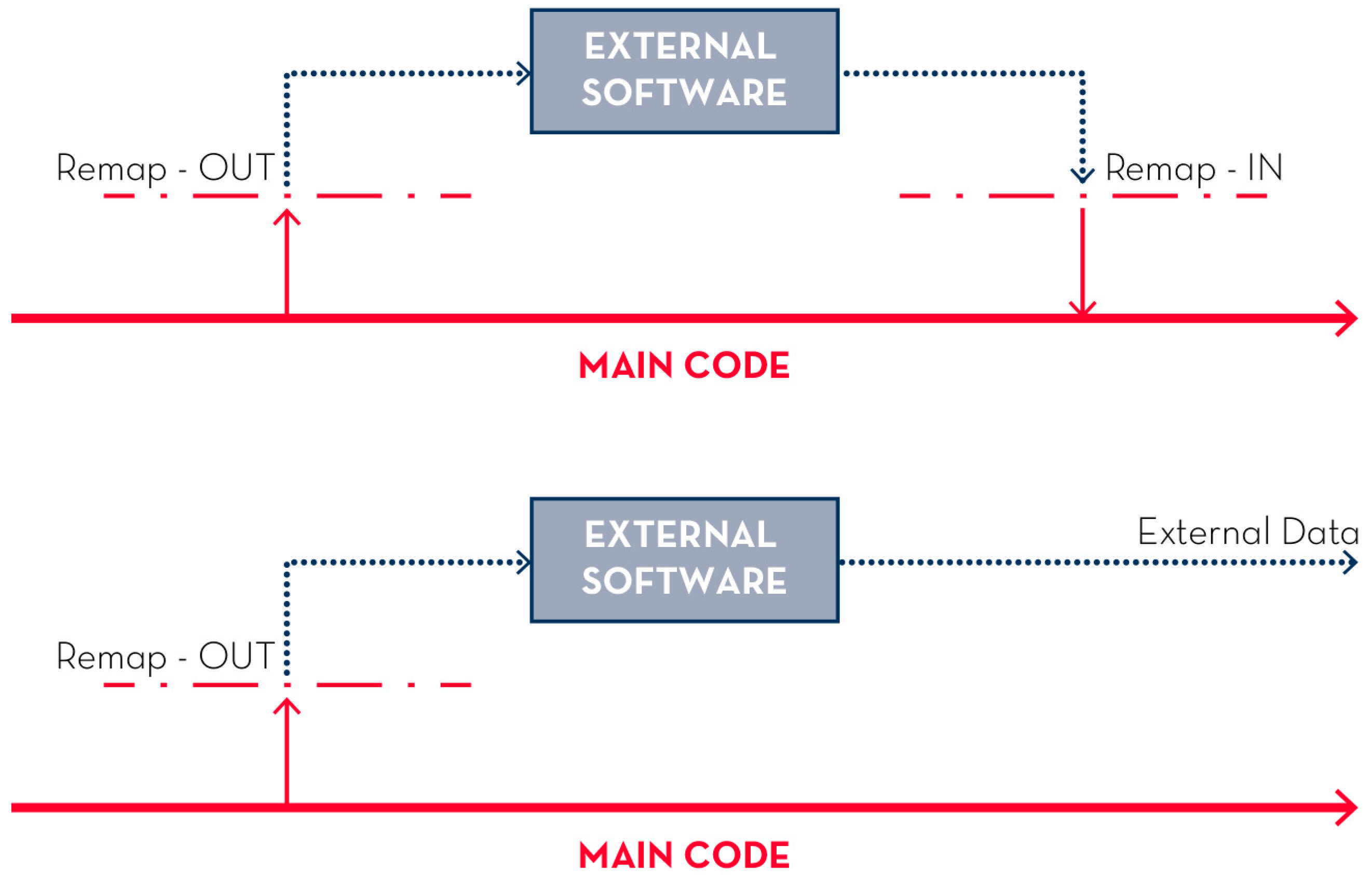
Figure 1. Schematic representation of the two data processes, the biunivocal one (above) and univocal one (below).
Ijgi 11 00093 g001
Figure 2. Workflow to develop an HBIM model based on external digitised resources. The external data from different knowledge domains are mapped and flown to the parallel construction of 3D geometries and the corresponding HBIM objects and information (properties and relations).
Ijgi 11 00093 g002
Figure 3. Recursive process of definition and implementation of HBIM object properties through the collection and manipulation of external data.
Ijgi 11 00093 g003
Figure 4. VPL code translating the IQM parameters for the masonry categories to wall instances’ properties in the IQM Revit template.
Ijgi 11 00093 g004
Figure 5. The VPL code which defines, in a Revit template, the properties of the IQM in the three directions of the wall plane.
Ijgi 11 00093 g005
Figure 6. Part of VPL code that reads, for the selected walls, the values written by the IQM operator in the previously added IQM parameters.
Ijgi 11 00093 g006
Figure 7. Part of the code introducing the requirements of the Italian legislation on structural analysis of the built heritage into the calculation of IQMV, IQMFP e IQMN (Circolare No. 7/2019).
Ijgi 11 00093 g007
Figure 8. Portion of code reading, for selected walls, the wall typology.
Ijgi 11 00093 g008
Figure 9. Portion of code dedicated to the calculation of the IQM expressed for the three solicitations for the selected walls.
Ijgi 11 00093 g009
Figure 10. Last part of the code dedicated to writing the IQM category output as textual values within the instance properties created.
Ijgi 11 00093 g010
Figure 11. Schematic representation of the double nature of the process: on the one hand, the modelling and assessment phases, carried out by an IQM operator within the IQM Revit template, and the IQM calculation and results, automatically provided by the VPL code within the same template.
Ijgi 11 00093 g011
Figure 12. Structure from Motion model from the photogrammetry survey of a case study building in the historic centre of Cornillo Nuovo—SISMI project [41].
Ijgi 11 00093 g012
Figure 13. HBIM model of a case study building in the historic centre of Cornillo Nuovo—SISMI project [41].
Ijgi 11 00093 g013
Figure 14. Properties of a wall in the IQM Revit Template, with the IQM parameters (input—red) filled in by the IQM operator and the automatically returned IQM category values (output—blue), applied to a case study building in the historic centre of Cornillo Nuovo—SISMI project [41].
Ijgi 11 00093 g014
Figure 15. Properties of a wall in the IQM Revit Template, with the IQM parameters (input—red) filled in by the IQM operator and the automatically returned IQM category values (output—blue), applied to a case study building in the historic centre of Cornillo Nuovo—SISMI project [41].
Ijgi 11 00093 g015
Publisher’s Note: MDPI stays neutral with regard to jurisdictional claims in published maps and institutional affiliations.