Article

Research on Stability Design of Differential Drive Fork-Type AGV Based on PID Control

School of Mechanical and Power Engineering, Zhengzhou University, Zhengzhou 450001, China
*
Author to whom correspondence should be addressed.
Electronics 2020, 9(7), 1072; https://doi.org/10.3390/electronics9071072
Submission received: 1 June 2020 / Revised: 25 June 2020 / Accepted: 26 June 2020 / Published: 30 June 2020
(This article belongs to the Special Issue Electric Vehicles in Smart Grids)

Abstract

:
As one of the important components of intelligent warehousing logistics, Automated Guided Vehicles (AGVs) have greatly improved the efficiency of warehousing operations. AGVs are responsible for the delivery of goods in warehousing and logistics, and it is extremely important to maintain a stable running state. In this paper, an AGV in-situ steering dynamic model is established according to the actual size, and the center deviation phenomenon during AGV steering is theoretically analyzed to obtain the parameters that affect the AGV’s in-situ steering stability. Secondly, the dynamic simulation method is used to analyze the law of the stability of the AGV in-situ steering parameters to verify the correctness of the theoretical derivation equation. According to the analysis results, the motion parameters related to AGV in-situ steering are analyzed, and a reasonable design scheme is given. Based on the optimized fork-type AGV, the AGV in-situ steering control strategy is studied, and the adaptive fuzzy PID control algorithm is used to construct the fork-type AGV steering control system. Then the software and hardware design of the AGV steering control system is carried out. The optimized fork-type AGV has been turned to work stably after commissioning, meeting the actual work requirements.

1. Introduction

An Automated Guided Vehicle (AGV) is an automated vehicle that is powered by a battery and can automatically travel along a planned path [1,2,3]. It belongs to the category of robots and is widely used in storage, docks, airports, libraries, and other industries [4,5,6]. AGVs have become an important part of the digital workshop, which is an important reflection of the level of intelligence in the workshop.
In 1953, the American Basrrett Company developed the first AGV. AGV technology continues to develop, especially after the application of computer control systems in the field of AGV control systems, improving AGV performance [7,8,9]. However, with the improvement of manufacturing technology, people have put forward higher requirements for AGV operation stability [10].
An AGV is a mobile robot, which is a comprehensive multi-disciplinary technology [11,12]. According to different classification forms, AGVs can be divided into many types, and according to the guidance method they can be divided into magnetic guidance AGVs, visual guidance AGVs, laser guidance AGVs, inertial guidance AGVs, etc.; according to the driving mode, they are mainly divided into single steering wheel drive AGVs, double steering wheel drive AGVs, four steering wheel drive AGVs, omnidirectional AGVs driven by Mecanum wheel and dual wheel differential drive AGVs, etc. [13,14]; fork-type AGVs are the main type of AGV in industrial workshops. In the complex system of automated warehousing, it not only needs to complete a series of tasks such as picking, storage, transportation, and cargo collection, but also guarantees the stability and safety of vehicle operation [15].
The fork-type AGV is a kind of AGV that is used more frequently. Researchers have analyzed the fork-type AGV mainly in terms of their control systems. For example, Kodagoda et al. [16] studied the development and practical application of an intelligent stable fuzzy proportional differential-proportional integral (PD-PI) controller in AGV steering and speed control; Yamamoto Hidehiko [17] described a method for controlling Autonomous Decentralized Flexible Manufacturing Systems (AD-FMS), which uses memory to determine the priority of competitive hypotheses; Zhang Huan and Qin Gang [18] designed a fixed-path AGV, using a battery and a Direct Current (DC) motor as the driving device. A steering gear controlled the AGV’s steering, and a single-chip microcomputer was used to control the various modules to work together to achieve automatic navigation; Jiang Xiaolong of Hefei University of Technology [19] designed a latent traction AGV with a navigation method of magnetic strip guidance and a driving method of two-wheel differential drive.
In addition to the research on the control system, most research on the structure of forklifts is focused on heavy-duty forklifts, which are more concentrated on the forks carrying heavy objects. Strength analysis of forks is carried out to optimize the design. Zhao Qingfu and Wen Huaixing [20] optimized the fork part of the forklift. A fork structure that meets the requirements is obtained, which not only saves materials, but also reduces the power of the trolley. Sun Binbin, Liu Nanyou et al. [21] conducted a static analysis on the fork structure of a fork-type AGV, and obtained the stress concentration area and the parts prone to deformation of the fork structure. Chen Huang [22] discussed the influence of forklift load, lifting speed, and road surface tilt angle on the stability of the forklift, and obtained the change of the longitudinal and lateral stability of the forklift and the change of the support force of the rear wheel of the forklift.
In summary, there is a lack of analysis of the influence of the structure of the car body on the stability of the AGV, and there is also a lack of research aimed at improving the stability of the car body. This paper studies a differential fork-type AGV (as shown in Figure 1). The AGV has a tail flick and roll phenomenon when turning on the spot, resulting in deviation from the original track and inability to read the guidance QR code information. Finally, the AGV route navigation failed. Aiming at the above problems, this paper uses a combination of dynamic analysis and simulation to study the AGV in-situ steering stability, determine the parameters that affect the stability of the fork-type AGV, and optimize the parameters that affect the stability of the fork-type AGV on this basis. Then, on the optimized AGV body, the steering control strategy of AGV is redesigned to further improve the stability parameters of AGV.

2. AGV Theoretical Analysis of In-Situ Steering Stability

The differential drive fork-type AGV model is shown in Figure 2. The front side of the AGV is a fork device, consisting of a lifting mechanism and a fork. The lifting mechanism is equipped with a servo motor to provide a stable drive for the lifting of goods. The back side of the AGV are batteries, counterweights, left- and right-wheel drive motors, and reducers.
The fork-type AGV uses two-dimensional code navigation, and its steering stability is reflected in the magnitude of the deviation of the center of rotation relative to the center of the two-dimensional code on the ground. The AGV in-situ zero-radius steering is achieved by two front drive wheels with equal and opposite movements. The rear wheels are two universal wheels (which can roll in any horizontal direction) and play a supporting role.
In Figure 3, the two driving wheels on the front side of the AGV are wheel 1 and wheel 2, and the two universal wheels on the rear side are wheel 3 and wheel 4. The center of mass of the car body is at C, and the corresponding physical quantities are shown in Table 1.
We performed a force analysis according to the in-situ acceleration steering process of the AGV, as shown in Figure 4 below.
The two driving wheels are subjected to ground forces F y 1 , F y 2 in the y direction and static friction forces F x s 1 , F x s 2 in the x direction. The rolling resistances F R 3 and F R 4 on the universal wheel are decomposed in the x and y directions to obtain F x R 3 , F x R 4 , F y R 3 , and F y R 4 . In addition, during the steering process, since the AGV center of mass C is not on its axis of rotation, a corresponding inertial force will be generated. The inertial force is decomposed in the x and y directions to obtain F x prime and F y prime, respectively. Using the D’Alembert principle [23], a dynamic analysis was performed. The balance equations are listed:
X = 0 ; F x s 1 + F x s 2 F x F x R 3 F x R 4 = 0
Y = 0 ; F y 1 F y 2 F y F y R 3 + F y R 4 = 0
M O ( F ) = 0 ; F x e + ( F x R 3 + F x R 4 ) l + ( F y R 3 + F y R 4 ) m ( F y 1 + F y 2 ) B 2 = 0
Since the vertical loads on both sides of the AGV are the same under the same road surface environment, the static frictional forces of the driving wheels 1 and 2 in the x direction are equal; then Equation (1) can be obtained:
F x s 1 = F x s 2 = F x + F x R 3 + F x R 4 2
From Equation (2) and Equation (3), we can get:
F y 1 = F x e + ( F x R 3 + F x R 4 ) l + ( F y R 3 + F y R 4 ) m B + F y + F y R 3 F y R 4 2
F y 2 = F x e + ( F x R 3 + F x R 4 ) l + ( F y R 3 + F y R 4 ) m B F y + F y R 3 F y R 4 2

2.1. AGV Unstable Steering Due to Side Slip

For the case of AGV side slip, according to Equations (1) and (4), it can be seen that when the AGV accelerates during the steering process, in the x direction, the maximum static friction force of the driving wheel 1 and the driving wheel 2 is less than the total force of other forces received by the AGV. This causes the AGV to slide sideways. In order to ensure the operational stability of the AGV, this situation should be avoided; therefore:
F x s 1 + F x s 2 F x + F x R 3 + F x R 4
Substitute the AGV related dimensions and coefficients into (7), after simplification:
l e l μ s m g m θ ¨ e
where θ ¨ is the angular acceleration of the AGV; μ s is the coefficient of static friction between the ground and the AGV wheel.
According to Equation (8), when the fork-type AGV turns, the maximum static friction force on the ground of the driving wheel is greater than the component of the inertial force generated by the AGV in the x direction, and the AGV can avoid the possibility of side slip. Properly increasing the static friction coefficient between the ground and the driving wheels can also reduce the possibility of AGV side slipping.

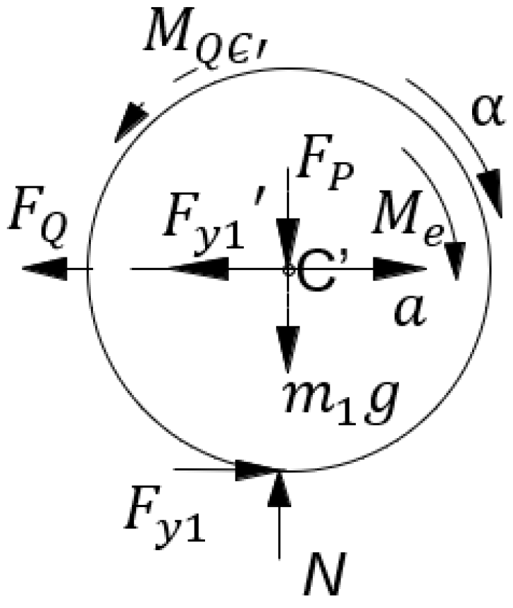
2.2. AGV Unstable Steering Due to Slipping of Drive Wheels

During the AGV’s in-situ steering process, when the torque formed by the force provided by the ground to the drive wheels cannot reach the moment of inertia of the circular motion of the AGV, the drive wheels slip. Similarly, when decelerating and steering, the torque generated by the braking force provided by the ground to the drive wheels is less than the moment of inertia of the AGV, the drive wheels slip. To avoid the occurrence of slip:
I θ ¨ μ N B
In the equation, μ N B represents the maximum force that the ground can provide the driving wheel (where μ is the attachment coefficient of the driving wheel, and N represents the supporting force of the ground to the two drives). I θ ¨ represents the moment of inertia of the AGV during turning. If the AGV is regarded as a regular cube, the moment of inertia of the AGV when turning is
I = 1 12 m ( a 2 + b 2 ) + m e 2
In the equation, a and b are the length and width of the AGV simplified into a regular cube. It can be seen that the moment of inertia of the AGV during steering depends on the length, width, and weight of the vehicle and eccentricity.
There is inertial force generated during the AGV steering process, causing the load on the AGV to shift. Unlike the in-situ steering, the shift of the load on both sides may cause the AGV to tip over during the steering process. As shown in Figure 4, the AGV has inertial component forces   F x and F y in the x and y directions. F x and F y both cause load shift during AGV steering, F x causes load transfer on both sides of the AGV, and F y causes load transfer on the front and rear of the AGV.
I θ ¨ ( l e l × 1 2 m g ( l e ) F x H l B 1 2 F y H l ) μ B
Comparing Equation (9) and Equation (11), it can be seen that when the AGV turns, the presence of inertial forces causes the AGV load to shift, which will cause the AGV to slip more easily. In addition, as can be seen from Equation (11), the AGV steering angular acceleration, eccentricity, and the adhesion coefficient between the ground and the driving wheels, as well as the AGV size parameters, all affect the AGV’s steering stability.

2.3. AGV Unstable Steering due to the Difference in Acceleration Values of the Two Drive Wheels

The single driving wheel when AGV is turning is analyzed. The force analysis of driving wheel 1 is shown in Figure 5. The radius of the driving wheel 1 is r , the mass is m 1 , the pressure of the vehicle body on the driving wheel 1 is F P , the acceleration of the driving wheel is a , the angular acceleration is α , the driving moment on the driving wheel 1 is M e , the support force of the ground to the drive wheel 1 is N , the inertial force of the drive wheel in plane motion is F Q = m 1 a , the moment of inertia is M Q C = I C α , and the inertial force F y component is F y 1 generated by the AGV during steering. Then there is:
X = 0 ; F y 1 F y 1 F Q = 0
Y = 0 ; N m 1 g F P = 0
M C ( F ) = 0 ; ( F y 1 + F Q ) r M e + M Q C = 0
According to the above equation, obtain:
a = M e F y 1 r 2 m 1 r
Similarly, after analyzing the driving wheel 2, obtain:
a = M e + F y 1 r 2 m 1 r
From Equation (15) and Equation (16), because F y 1 0 ( F y = m θ ˙ 2 e ), unequal acceleration (the body’s steering angular acceleration and drive wheel displacement acceleration are both determined by the drive wheel’s angular acceleration; hence, the AGV acceleration studied in this paper is the rotation angular acceleration of the driving wheel) of the left and right drive wheels leads to unstable AGV steering.

3. AGV Simulation Analysis

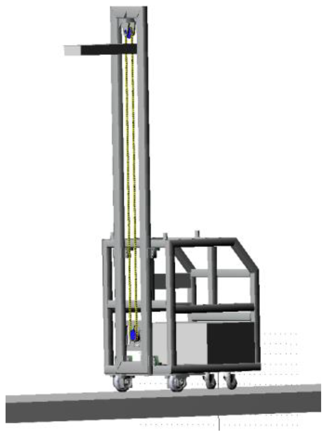
3.1. Simulation Model Establishment

In order to obtain the dynamic characteristics of fork-type AGV in-situ steering and analyze the influencing factors of the dynamic characteristics in detail, this paper establishes the fork-type AGV model and the corresponding operating environment in SolidWorks according to its actual size.
When modeling in SolidWorks software (Dassault Systemes, Concord, Massachusetts, USA), the structure of the fork-type AGV is simplified, and some parts and processes that are not related to the simulation or have little impact on the simulation are ignored [24]. The specific simplification is as follows:
  • Fillets and chamfers that do not affect AGV stability are ignored;
  • Elements that do not affect the strength and stiffness of AGV are ignored;
  • The number of parts in the model can be reduced, and the calculation speed can be accelerated by setting some connecting parts as a bonding relationship;
  • The chain drive part of the fork-type AGV is removed. For this kind of flexible part, it needs to be built in the ADAMS software (Mechanical Dynamics Inc, Winter Haven, FL, USA) environment to reflect its actual stress condition;
  • In addition, as shown in Figure 6, the fork in the fork-type AGV model is relatively complex, and this topic is aimed at the dynamics research of the fork-type AGV steering simulation. Therefore, before importing Adams, the fork in the AGV model is removed, and then a simplified fork with the same size, volume and weight is created in the ADAMS software;
  • The simulation model includes the AGV model and the corresponding operating environment, and a large area of a rectangular block should be assembled in the place where the AGV’s four wheels have contact as the AGV running road.
Adams/machine chain, a chain drive module in ADAMS, is used to build the required chain drive model. Then the fork is replaced by a rectangular block, and the weight is set as the sum of the fork weight and the maximum load weight. Finally, it is fixed on the chain, and the complete model is as shown in the Figure 7.
AGV body frame, fork, and counterweight are made of ordinary steel; the wheels are made of polyurethane; the pavement is made of concrete. The material properties of each component are shown in the Table 2 below. The mass of battery and counterweight are directly set in the software according to the actual mass.
In the fork-type AGV, most of the connections among the frame, battery, counterweight, and frame are constrained to be fixed joint. The connection between the wheel and its shaft is a revolving joint, in which the cardan wheel needs to be set as two mutually perpendicular revolving joints to ensure the horizontal 360° rotation of the universal wheel. The constraint between the wheel and the ground is set as the contact mode.
Set the drive parameters for the fork-type AGV. In the process of in-situ steering, AGV starts in the way of uniform acceleration, and then decelerates to the end of 90° steering. Speed drive is added to the revolving joint of the two driving wheels, and a STEP function is used to define the rotating speed of the driving wheels, so as to realize the steering process of first, accelerating to start; then uniform speed; and finally, decelerating to stop.
The format of the STEP function is as follows:
STEP ( x , x 0 , h 0 , x 1 , h 1 )
In the equation, x is the variable; x 0 , x 1 is the initial and termination value of variable x; h 0 , h 1 is the function value corresponding to x 0 and x 1 .
As shown in Figure 8, the curve reflects the specific change of the STEP function.
Then the speed driving function of driving wheel 1 is: STEP(time, 0, 0, 0.5, −596 d) + STEP(time, 1, 0, 1.5, 596 d). The speed driving function of driving wheel 2 is: STEP(time, 0, 0, 0.5, 596 d) + STEP(time, 1, 0, 1.5, −596 d), where the “d” in the function means degree, and “596 d” means 596°/s. In this way, the fork-type AGV can realize in-situ steering.

3.2. Motion Simulation of Fork-Type AGV

After the parameters of the simulation model are set, the dynamic simulation of the fork-type AGV is carried out. When the steering speed is adjusted, the fork-type AGV will lose its tail, which is consistent with the actual experiment. It shows that the simulation model is practical, and the simulation experiment is reasonable.
According to the above theoretical derivation, the parameters that affect the in-situ steering stability of fork-type AGVs are obtained. The influence of the parameters of the fork-type AGV’s in-situ steering angular velocity θ ˙ , the angular acceleration θ ¨ , and the friction coefficient between the ground and the wheel are simulated respectively to verify the theory derived above.

3.2.1. Effect of Velocity on AGV Steering Stability

The velocity refers to the steering angular speed during the AGV steering process, that is, the uniform speed stage. Since the steering angular velocity of the car body depends on the angular velocity of the driving wheel, for the convenience of setting, this paper gives the output curve of the center velocity of the driving wheel at different angular velocities of the AGV driving wheel in the simulation process. In order to be able to clearly compare the stability of the AGV at different speeds, the rotational angular velocity of the driving wheel was set to 298π/180 rad/s, 1445π/180 rad/s, and 2023π/180 rad/s in the simulation. The maximum deviation of the AGV rotation center at different speeds is shown in Figure 9.
From the results of simulation experiments, it can be seen that when the AGV is at a low speed during steering, the maximum deviation of the center of rotation is extremely small, less than 1.5 mm. As the speed increases, the deviation of the center of rotation becomes larger. Consistent with the previous theoretical analysis.

3.2.2. Effect of Acceleration on AGV Steering Stability

For the convenience of setting, the acceleration and deceleration time of the AGV to reach the maximum speed (the driving wheel rotation angular velocity of 596π/180 rad/s) are controlled to change its acceleration value. Similarly, the effect of acceleration on AGV steering stability is analyzed by the linear velocity curve of the driving wheel and the displacement curve of the center of rotation. The maximum deviation of the center of rotation of the AGV under different acceleration times is shown in Figure 10.
From Figure 8, it can be clearly seen that when the acceleration time is less than 0.3 s, the increase of the maximum deviation of the AGV rotation center is significantly accelerated. Before that, it was in a relatively stable state. When the acceleration reached a certain value, the AGV slipped. However, the effect of acceleration on the speed difference between the two drive wheels is not particularly great. Overall, it is consistent with the analysis of the dynamic equilibrium equation above.

3.2.3. Effect of Static Friction Coefficient on AGV Steering Stability

The coefficient of static friction refers to the coefficient of friction between the wheel and the ground. In this paper, by controlling other conditions unchanged and performing simulation experiments on different static friction coefficients, the following AGV rotation center offsets are obtained:
It can be seen from Figure 11 that the static friction coefficient has a greater influence on the fork-type AGV in-situ steering. When the static friction coefficient between the AGV drive wheel and the ground is 0.1, the AGV steering is very unstable, the maximum deviation of the rotation center is close to 40 mm. When the static friction coefficient is 0.6, the AGV steering performance is quite stable. In addition, in the simulation, the effect of the static friction coefficient between the driving wheel and the ground on the in-situ steering of the AGV is in line with the theoretical derivation.

4. AGV Optimization

According to the previous analysis results, the AGV’s motion parameters are optimized to ensure the AGV’s stable steering. The steering angular acceleration should be as large as possible to improve the AGV’s working efficiency. At this time, the optimal steering angular acceleration can be obtained. Then, the friction coefficient between the wheel and the ground is mainly limited by the wheel material and the fork-type AGV working site, and it is relatively difficult to further improve. This paper still uses the original wheel material and the original ground without further optimization. According to relevant information [25,26,27], the static friction coefficient in the above situation is 0.6.

4.1. Optimization of AGV’s Motion Parameters

4.1.1. Calculation of AGV Steering Acceleration

Substitute the AGV’s car body structure parameters into Equation (9) and Equation (11). For Equation (8), because the AGV eccentricity is small, the calculated angular acceleration is very large, and the theoretical design acceleration value of AGV cannot reach this value.
Therefore, the value of the steering angular acceleration is determined according to Equation (11). Substitute the relevant parameters and find the critical angular acceleration α = 0.117   rad / s 2 when the AGV turns.
The angular acceleration of AGV driving wheel can be slightly less than the critical value, which can ensure that the fork-type AGV is steered stably and the steering is highly efficient.

4.1.2. Calculation of AGV Steering Speed Value

Under the condition of ensuring a certain steering acceleration, simulation experiments under different steering speeds are conducted to find that AGV can stabilize the steering and can complete the optimal speed value of the steering at a faster speed. The simulation results are shown in Figure 7. Because the AGV uses a two-dimensional code navigation method, according to the actual situation, the landmark is composed of a 4 × 4 QR code label (85 mm × 85 mm); as long as the center of the camera reading window can be within the tag, the AGV’s position can be obtained. The maximum allowable deviation distance can be calculated to be 60.1 mm. It can be seen from Figure 9 that when the angular speed of the driving wheel reaches 2312π/180 rad/s, the vehicle body deviation does not exceed 60 mm. Therefore, in order to ensure stable steering and improve the AGV’s working efficiency, the angular velocity of the driving wheel can be selected from 2023π/180 rad/s to 2312π/180 rad/s.

4.2. AGV Control Strategy Optimization

The AGV motion parameters were optimized, and the AGV’s steering performance was greatly improved. Due to the characteristics of front-wheel differential steering, the optimized fork-type AGV still has the problem of structural eccentricity. At the same time, due to the machining and transfer errors of mechanical parts, the fork-type AGV still has deviations in in-situ steering. In order to further improve the steering stability of the AGV and reduce the deviation of the AGV in-situ steering, thereby improving the performance of the AGV and promoting the efficiency and reliability of the warehouse logistics work, this paper studies the fork-type AGV in-situ steering control strategy.
In this paper, the fork-type AGV has a deviation e between the center of rotation and the origin of the ground during the in-situ steering process. The deviation is detected by a visual sensor, and the change ec between the current deviation and the last deviation is calculated. According to the experimental collection of the visual sensor, the maximum ec is 20 mm in the steering process; then its basic theory domain is [−20, 20]. Then it is fuzzified, quantified by a 1/5 scale factor, transformed into the domain of fuzzy sets [−3, −2, −1, 0, 1, 2, 3], and expressed in fuzzy language as NB, NM, NS, ZO, PS, PM, PB. Similarly, for the fuzzy outputs ∆Kp, ∆Ki, and ∆Kd, first, determine their basic domain through debugging, and then perform fuzzification, using the same fuzzy language above.
For defuzzification, this paper uses the center-of-gravity method. Substitute the obtained membership degree and the corresponding abscissa into the following equation to find the final output value of fuzzy inference.
y = i = 1 n μ A i ( x ) μ B i ( y ) z i i = 1 n μ A i ( x ) μ B i ( y )
In the equation, μ A i ( x ) , μ B i ( y ) is the membership degree; z i is the abscissa corresponding to membership degree.

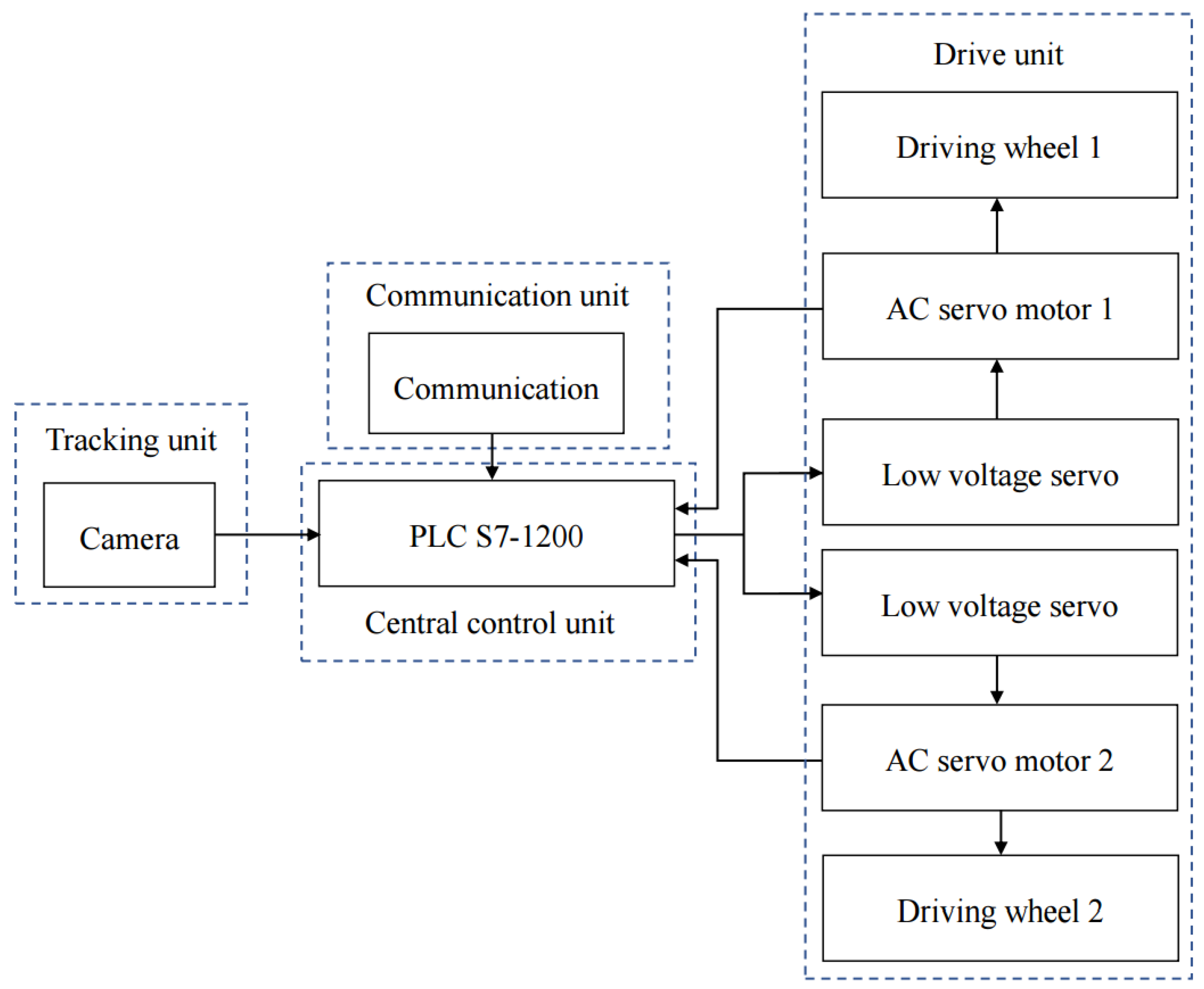
4.2.1. AGV Steering Control System Hardware Design

According to the steering control requirements of the fork-type AGV, the fork-type AGV steering control system is mainly composed of the following parts: central control unit, communication unit, tracking unit, and drive unit. Its block diagram is shown in Figure 12.

Control Unit Design

The Siemens S7-1200 series Programmable Logic Controller (PLC) selected in this topic is a compact, modular, small to medium-sized PLC with extremely strong communication functions and simple and reasonable design of the command system. Figure 13 shows the physical picture of S7-1200 PLC (SIEMENS, Munich, Germany).

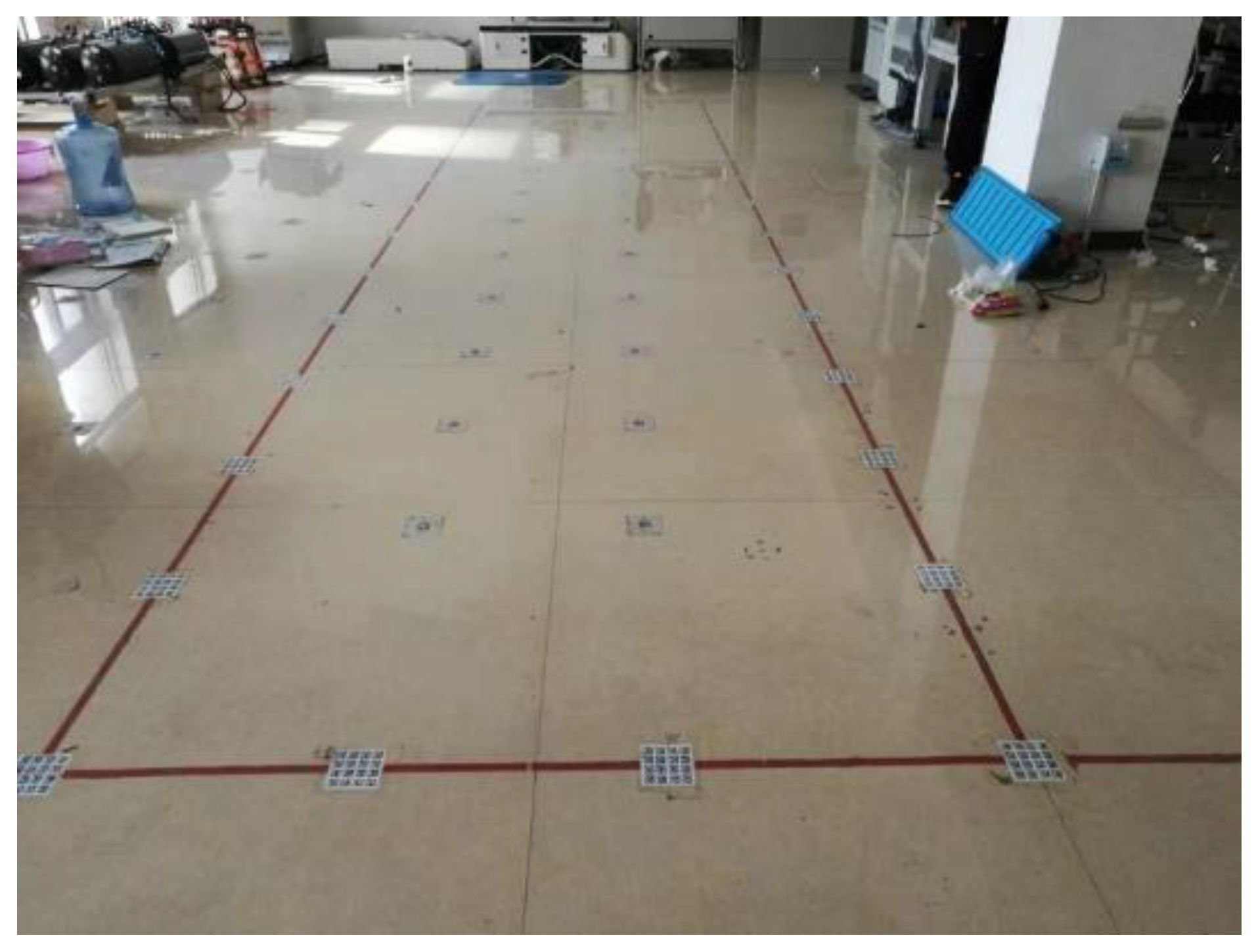
Tracking Unit Design

The AGV steering control of this subject needs to know the position of the AGV relative to the fixed center of the ground during the steering process, combined with the actual cost, to select the PEPPERL FUCHS PGV 100 vision sensor. In label mode, the measurement accuracy can reach ± 0.2   mm and ±   0.1 ° . The output information includes status information, Tag number (001 ~ 99 999 999), X direction deviation value, Y direction deviation value, angle deflection value, and alarm code. The label mode of the PGV100 vision sensor (PEPPERL FUCHS, Mannheim, Germany ) requires a specific, matching tag label (composed of a QR code). As shown in Figure 14, the label is attached to the experiment site.

Communication Unit Design

When the AGV turns, it first collects the AGV position signal through the vision sensor, and then transmits the position information to the PLC through communication. The PLC undergoes program processing and outputs the corresponding speed adjustment signal to the drive unit. This mainly involves the communication between the vision sensor and the PLC and the communication between the PLC and the driver.
RS485 communication is adopted between the visual sensor and the PLC. RS485 is a low-cost and simple-structure communication method. Although its communication rate is slow, it is significantly improved compared to RS232 [28], and the distance between PLC and sensor in this subject is very short; hence, RS485 is sufficient for communication between the visual sensor and the PLC. RS485 communication between the PLC and the PGV requires the expansion of the CM 1241 RS485 communication module.
The communication method between PLC and drive is CANopen. The fork-type AGV in this subject needs to adjust the speed of the drive wheel in real time during steering control, and the requirements for real-time stability and reliability are extremely high. CANopen is a high-level communication protocol based on the Controller Area Network (CAN). The CAN bus has the advantages of a good real-time, fast communication rate, long transmission distance, strong anti-interference ability, and high reliability. This paper selects the CM CANopen communication module to be perfectly compatible with S7-1200 and can be used as a communication bridge between the PLC and CANopen/CAN devices.

Drive Unit Design

In this paper, AGV uses two front-wheel differential drives. The driving motor is the main source of AGV driving force. The power performance and load capacity of AGV are determined by the driving motor. From the aspect of performance, the servo motor is selected as the AGV drive motor. Compared with the DC servo motor, the Alternating Current (AC) servo motor is controlled by a sine wave, and the torque ripple is small [29].
The total weight of the AGV in this paper is about 150 kg, and the maximum load capacity of the fork is 10 kg. Therefore, the pressure of the fully loaded AGV on the ground is F n = 1568   N . Since the AGV’s operating environment is level ground, there is no need to consider ramp resistance. As the AGV’s running speed is very low, air resistance can be ignored. Therefore, during operation, the AGV only needs to overcome rolling friction and acceleration resistance during acceleration:
  F = F R + F a
In the equation, F R is the rolling resistance of the AGV, and F a is the acceleration resistance. Since the rolling resistance coefficient is small, the rolling resistance is much smaller than the acceleration resistance; hence, the rolling resistance can be ignored. The designed maximum acceleration of the fork-type AGV is 2 m/s2, then the acceleration resistance F a = M a = 160 × 2   N = 320   N . Therefore, the radius of the AGV drive wheel is 0.05 m, and the total drag torque can be obtained   M = F × r = 320 × 0.05 = 16   N · m . According to the initial motor’s rated speed of 3000 rpm, the design requires a maximum AGV speed of 2 m/s, and a reduction ratio of 7.85 can be calculated. Therefore, a planetary gearbox with a reduction ratio of 10 is selected. Then the rated torque of a single drive motor is greater than 0.8   N · m .
As the motor, the AC servo motor model ACM6040V60H-A5 of Raytheon (Raytheon Company, Waltham, Massachusetts, USA) is selected. The rated torque is 1.27   N · m , which can meet the actual torque requirements. Its rated speed is 3000 rpm, and the maximum speed is 4000 rpm. According to the previous analysis, CANopen communication is selected for real-time and stabile communication between the PLC and the drive unit; hence, the driver chooses the matching driver of the LD5-CAN series of Raytheon. The low-voltage AC servo drive is powered by low-voltage DC and has a compact structure, which can be adapted to Siemens PLC and meets the design requirements of the AGV.
The fork-type AGV steering control system is designed according to the hardware wiring principle (as shown in Figure 15).

4.2.2. AGV Steering Control System Software Design

The AGV steering control system center designed in this paper is PLC. First, the PLC collects the position and angle information of the AGV from the visual sensor during the steering process. After data processing and fuzzy PID algorithm control, the adjustment amount of the driving wheel speed is obtained, and it is communicated to the controller through communication. Then the controller drives the motor to realize the speed adjustment of the drive wheels. Then the controller drives the motor to realize the speed adjustment of the drive wheels. During the entire steering process, it continuously collects position information and continuously adjusts the speed of the two drive wheels until it stops at 90° turning and the steering control is completed.
This paper selects TIA Botu software (SIEMENS, Munich, Germany) as the programming platform to design the fork-type AGV steering control program. TIA Botu software highly integrates device configuration and programming, which greatly facilitates the development and debugging of the automation systems by the user. In the software, a variety of programming languages are provided for users to choose from, including ladder diagram LAD, statement list STL, function block diagram FBD, structured control language SCL, and graphical GRAPH [30]. Before writing the program, you need to configure the relevant hardware and configure all information related to the hardware of the entire system.
The entire AGV steering control program mainly includes: The communication program between the visual sensor and the PLC, the processing program for the error data obtained from the visual sensor, the fuzzy rule-based query program, the PID control program, and the communication program between the PLC and the driver.
After the program is written, it is compiled and then downloaded to the AGV PLC for on-site debugging. After commissioning, the fork-type AGV in-situ steering is stable. Figure 16 shows the trajectory of the AGV’s on-site movement (the gyro angle information is used to detect the deviation of the AGV linear trajectory angle). The AGV turns in 5 s to 8 s; the maximum deviation from the beginning is 5 mm. After adjustment, the deviation is reduced to less than 2 mm. The maximum deviation of the initial AGV, as well as the adjustment effect during operation, have reached the expectations.
After debugging, the fork-type AGV turns stably on the spot, which can ensure that the vision sensor can read the QR code stably during the turning process. The AGV can meet the actual work requirements.

5. Conclusions

In this paper, aiming at the existing fork-type AGV steering instability, the stability of AGV in-situ steering is analyzed, and the related motion parameters are optimized. Combined with the corresponding control strategy, the AGV steering control system is designed to improve the fork-type AGV steering stability. It provides a theoretical basis and design ideas for improving the stability and safety of AGV forklifts. The main work of this paper includes the following aspects:
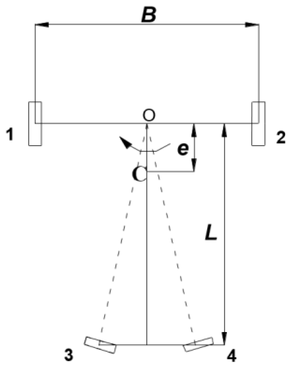
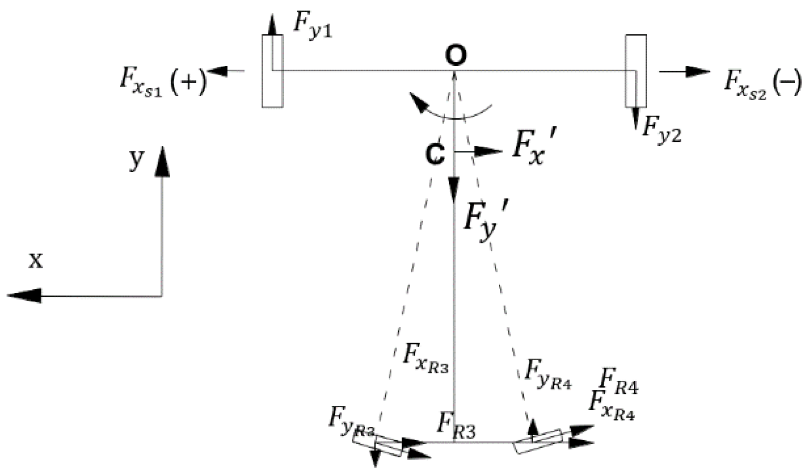
  • In this paper, three kinds of unstable situations of fork-type AGV in-situ steering are analyzed theoretically: Sideslip in the process of AGV in-situ steering, slip in the driving wheel, and difference in acceleration between the two driving wheels. The physical model and the corresponding mathematical model are established, and the structure and motion parameters that affect the stability of AGV in-situ steering are obtained: the steering angular velocity, acceleration, eccentricity, the static friction coefficient between the ground and the driving wheel, and the moment of inertia (related to the size and weight of AGV body) when AGV is turning;
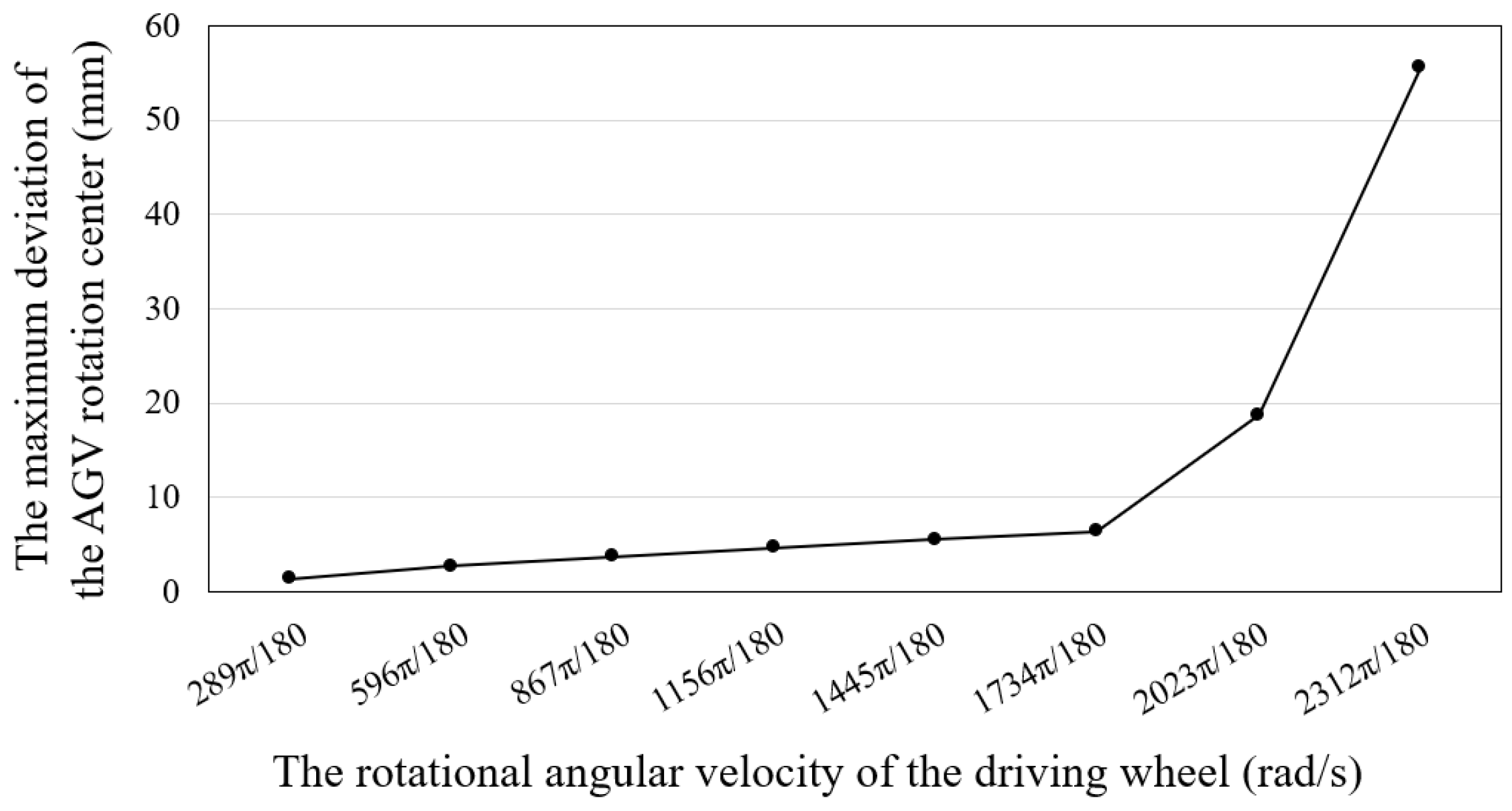
  • The simulation model of the fork-type AGV’s in-situ steering is established by using ADAMS software. Based on the simulation experiment of the motion parameters which influence the stability of the AGV’s in-situ steering obtained from the previous theoretical analysis, the effects of speed, acceleration, and the static friction coefficient on the stability of the AGV’s in-situ steering are analyzed. It is found that when the speed increases to 2023π/180 rad/s, the in-situ steering stability of the AGV decreases significantly; when the acceleration time is less than 0.3 s, the maximum deviation of AGV rotation center increases significantly, and the AGV slips; when the static friction coefficient between the AGV’s driving wheel and the ground increases from 0.1 to 0.3, the steering stability of the AGV improves significantly. This is consistent with the results of the theoretical derivation, which verifies the rationality of the theoretical derivation;
  • Reasonable suggestions are made for the speed and acceleration of AGV in-situ steering. Aiming at the deviation of the AGV’s rotation center during the AGV’s in-situ steering, the corresponding steering control strategy is obtained through research. The flexible and stable fuzzy adaptive PID control algorithm is used to design the corresponding steering control strategy. The hardware and software of the corresponding AGV in-situ steering control system are designed to realize AGV steering control. After debugging, the optimized forklift AGV turned to work stably, meeting the actual work requirements.

Author Contributions

R.Z. and T.W. theoretical analysis; R.D. simulation verification; R.D. and T.W. conceived and designed the experiments; R.D. and R.Z. performed the experiments; R.D. wrote the paper; D.Q. and T.W. commented and edited. All authors have read and agreed to the published version of the manuscript.

Funding

This research was funded by the National Natural Science Foundation of China—Research on the integrated design method of structure-material-performance of automobile body based on big data (51705468), and the Key Scientific Research Projects of Henan Province—Automobile Multidisciplinary Design Optimization theory and key technology research based on big data (15A460032).

Conflicts of Interest

The authors declare no conflict of interest.

Nomenclature

AGVAutomated Guided Vehicle
QR codeTwo-dimensional code
CANController Area Network
PLCProgrammable Logic Controller
mMass
gAcceleration of gravity
BTrack of left and right wheels
lTrack of front and rear wheels
eEccentricity(m)
HCentroid height
fRRolling friction coefficient
μSCoefficient of static friction

References

  1. Long, J.; Zhang, C.L. The Summary of AGV Guidance Technology. Adv. Mater. Res. 2012, 591–593, 1625–1628. [Google Scholar] [CrossRef]
  2. Field, B.F.; Kasper, G. Automated Guided Vehicle. U.S. Patent 4,996,468, 20 February 1991. [Google Scholar]
  3. Vis, I.F.A. Survey of research in the design and control of automated guided vehicle systems. Oper. Res. 2006, 46, 435–436. [Google Scholar] [CrossRef]
  4. Rashidi, H.; Tsang, E.P.K. A complete and an incomplete algorithm for automated guided vehicle scheduling in container terminals. Comput. Math. Appl. 2011, 61, 630–641. [Google Scholar] [CrossRef]
  5. Nana, G. Research on Plan for AGV Applied to Automated Logistics System. Master’s Thesis, Xi’an University of Science and Technology, Xi’an, China, 2010. [Google Scholar]
  6. Čerić, V. Simulation Study of an Automated Guided-vehicle System in a Yugoslav Hospital. J. Oper. Res. Soc. 2017, 41, 299–310. [Google Scholar] [CrossRef]
  7. Ganesharajah, T.; Hall, N.G.; Sriskandarajah, C. Design and operational issues in AGV-served manufacturing systems. Ann. Oper. Res. 1998, 76, 109–154. [Google Scholar] [CrossRef]
  8. Umar, U.A.; Ariffin, M.K.A.; Ismail, N.; Tang, S.H. Hybrid multiobjective genetic algorithms for integrated dynamic scheduling and routing of jobs and automated-guided vehicle (AGV) in flexible manufacturing systems (FMS) environment. Int. Ournal Adv. Manuf. Technol. 2015, 81, 2123–2141. [Google Scholar] [CrossRef]
  9. Fazlollahtabar, H.; Saidi-Mehrabad, M. Methodologies to Optimize Automated Guided Vehicle Scheduling and Routing Problems: A Review Study. J. Intell. Robot. Syst. 2015, 77, 525–545. [Google Scholar] [CrossRef]
  10. Butdee, S.; Suebsomran, A. Automatic guided vehicle control by vision system. In Proceedings of the IEEE International Conference on Industrial Engineering and Engineering Management, Hong Kong, China, 8–11 December 2009. [Google Scholar]
  11. Wang, M.S.; Chen, S.C.; Chuang, P.H.; Wu, S.Y.; Hsu, F.S. Neural Network Control-Based Drive Design of Servomotor and Its Application to Automatic Guided Vehicle. Math. Probl. Eng. 2015, 2015, 612932. [Google Scholar] [CrossRef] [Green Version]
  12. Weyns, D.; Holvoet, T. Architectural design of a situated multiagent system for controlling automatic guided vehicles. Int. J. Agent Oriented Softw. Eng. 2008, 2, 90–128. [Google Scholar] [CrossRef] [Green Version]
  13. Weitao, W. The Overall Scheme and Key Technology Research of Logistics Transportation AGV. Master’s Thesis, Shenyang Ligong University, Shenyang, China, 2013. [Google Scholar]
  14. Rehman, N.U.; Asghar, S.; Usman, M.; Fong, S.; Cho, K.; Park, Y.W. High level classification recommended decision making for Autonomous Ground Vehicle (AGV). J. Comput. Theoret. Nanosci. 2016, 13, 4284–4292. [Google Scholar] [CrossRef]
  15. Xuesong, G.; Yuhao, L.; Liqiang, Z.; Zhihua, C. Pure Rolling Steering System Design and Research on Non-sideslip Steering Control for Wheeled AGV. Trans. Chin. Soc. Agric. Mach. 2018, 56, 101230. [Google Scholar]
  16. Kodagoda, K.R.S.; Wijesoma, W.S.; Teoh, E.K. Fuzzy speed and steering control of an AGV. IEEE Trans. Control Syst. Technol. 2002, 10, 112–120. [Google Scholar] [CrossRef] [Green Version]
  17. Hidehiko, Y.; Takayoshi, Y. Intelligent AGV Control of Autonomous Decentralized FMS by Oblivion and Memory. Key Eng. Mater. 2010, 447–448, 326–330. [Google Scholar]
  18. Cho, H.; Song, H.; Park, M.; Kim, J.; Woo, S.; Kim, S. Independence localization system for Mecanum wheel AGV. In Proceedings of the IEEE RO-MAN, Gyeongju, Korea, 26–29 August 2013. [Google Scholar]
  19. Xiaolong, J. The Key Technology Research on Magnetic Guided and Double Wheels Differential Speed Automated Guided Vehicle. Master’s Thesis, Hefei University of Technology, Hefei, China, 2016. [Google Scholar]
  20. Qingfu, Z.; Huaixing, W. Optimization design of the small stacking robot fork device. Manuf. Autom. 2013, 35, 1–3. [Google Scholar]
  21. Binbin, S.; Nanyi, L.; Lihui, W. Stability Analysis on Fork-type AGV Based on ANSYS. Taiyuan Sci. Technol. 2016, 115–116, 120. [Google Scholar]
  22. Huang, C.; Shirong, Y. Stability Analysis of Forklift Based on ADAMS. Mach. Build. Autom. 2015, 4, 108–111. [Google Scholar]
  23. Yongyan, W. Theoretical Mechanics; Science Press: Beijing, China, 2019; pp. 309–312. [Google Scholar]
  24. Rui, C. The Stabilization Research of Fork-Type AGV Based on Virtual Prototyping Technology and Structure Optimization. Master’s Thesis, Mechanical Science Research Institute, Beijing, China, 2015. [Google Scholar]
  25. Sa, L. Research on Motion Stability of Drive-Module of Four-Wheel Independent-Steering AGV. Master’s Thesis, Huazhong University of Science and Technology, Wuhan, China, 2019. [Google Scholar]
  26. Jinchang, Z. Optimal Design Parking and Steering Stability Analysis of AGV. Master’s Thesis, North University of China, Taiyuan, China, 2019. [Google Scholar]
  27. Peng, Z. Research on Structural Design and Stability of Pallet Type AGV Forklift. Master’s Thesis, Anhui University of Science and Technology, Huainan, China, 2019. [Google Scholar]
  28. Ping, F. Design of Compressor Oil Injection Management System Based on RS485 and Ethernet Communicatio. Master’s Thesis, Qingdao University, Qingdao, China, 2017. [Google Scholar]
  29. Lifang, T. Research on Design and Test of Wheeled AGV System of Picking Robot Based on Pure-Rolling Steering. Master’s Thesis, Jiangsu University, Zhenjiang, China, 2016. [Google Scholar]
  30. Shuo, Z. Detailed application of TIA Botu software and S7-1200/1500 PLC; Electronic Industry Press: Beijing, China, 2017; pp. 254–273. [Google Scholar]
Figure 1. The physical picture of the Automated Guided Vehicle (AGV).
Electronics 09 01072 g001
Figure 2. The differential drive fork-type AGV model.
Electronics 09 01072 g002
Figure 3. AGV simplified model.
Electronics 09 01072 g003
Figure 4. Force analysis of AGV.
Electronics 09 01072 g004
Figure 5. Force analysis of drive wheel 1.
Electronics 09 01072 g005
Figure 6. Simplified fork-type AGV model.
Electronics 09 01072 g006
Figure 7. Fork-type AGV model.
Electronics 09 01072 g007
Figure 8. STEP function curve.
Electronics 09 01072 g008
Figure 9. The maximum deviation of rotation center at different angular velocities.
Electronics 09 01072 g009
Figure 10. The maximum deviation of rotation center under different acceleration time.
Electronics 09 01072 g010
Figure 11. The maximum deviation of rotation center under different static friction coefficient.
Electronics 09 01072 g011
Figure 12. Block diagram of the AGV steering control system.
Electronics 09 01072 g012
Figure 13. Programmable Logic Controller (PLC) physical diagram of S7-1200.
Electronics 09 01072 g013
Figure 14. Tag labeling experiment site.
Electronics 09 01072 g014
Figure 15. AGV steering control system diagram.
Electronics 09 01072 g015
Figure 16. AGV trajectory deviation: (a) Angle deviation; (b) Position deviation.
Electronics 09 01072 g016
Table 1. AGV structure physical quantities.
Physical QuantitySymbol
Mass (kg)m
Track of left and right wheels (m)B
Track of front and rear wheels (m)l
Eccentricity (m)e
Centroid height (m)H
Rolling friction coefficient f R
Coefficient of static friction μ s
Table 2. Material property settings.
Name of PartsMaterialModulus of Elasticity (N/mm2)Poisson’s RatioDensity (kg/mm3)
Body frame/fork/counterweightSteel2.07 × 1050.297.801 × 10−6
WheelPolyurethane83000.281.5 × 10−6
Working pavementConcrete3.5 × 1040.152.4 × 10−6

